New Holland T7.220 / T7.235 / T7.250 / T7.260 / T7.270 Auto Command. T7.220 / T7.235 / T7.250 / T7.260 Power Command Tractor. SERVICE MANUAL (2013)
SERVICE MANUAL
T7.220 / T7.235 / T7.250 / T7.260 / T7.270 Auto Command
T7.220 / T7.235 / T7.250 / T7.260 Power Command
Tractor
Part number 47524331
English
May 2013
SERVICE MANUAL
T7.220 AutoCommand , T7.220 Power Command , T7.235 AutoCommand ,
T7.235 Power Command , T7.250 AutoCommand , T7.250 Power Command ,
T7.260 AutoCommand , T7.260 Power Command , T7.270 AutoCommand
47524331 18/04/2013
EN
Link Product / Engine
Product
Market Product
Engine
T7.220
Power Command
Europe
F4DFE613L*A
T7.220
Power Command
North America
F4DFE613L*A
T7.220
Power Command
International
F4DFE613L*A
Region
T7.235
Power Command
Europe
F4DFE613K*A
T7.235
Power Command
International
F4DFE613K*A
Region
T7.235
Power Command
North America
F4DFE613K*A
T7.250
Power Command
North America
F4DFE613J*A
T7.250
Power Command
International
F4DFE613J*A
Region
T7.250
Power Command
Europe
F4DFE613J*A
T7.260
Power Command
North America
F4DFE613H*A
T7.260
Power Command
Europe
F4DFE613H*A
T7.260
Power Command
International
F4DFE613H*A
Region
T7.220
AutoCommand
Europe
F4DFE613L*A
T7.220
AutoCommand
International
F4DFE613L*A
Region
T7.235
AutoCommand
International
F4DFE613K*A
Region
T7.235
AutoCommand
Europe
F4DFE613K*A
T7.235
AutoCommand
North America
F4DFE613K*A
T7.250
AutoCommand
North America
F4DFE613J*A
T7.250
AutoCommand
Europe
F4DFE613J*A
T7.250
AutoCommand
International
F4DFE613J*A
Region
T7.260
AutoCommand
Europe
F4DFE613H*A
T7.260
AutoCommand
North America
F4DFE613H*A
T7.260
AutoCommand
International
F4DFE613H*A
Region
T7.270
AutoCommand
North America
F4DFE613G*A
T7.270
AutoCommand
International
F4DFE613G*A
Region
T7.270
AutoCommand
Europe
F4DFE613G*A
4752433118/04/2013
Contents
INTRODUCTION
Engine
10
[10.001] Engine and crankcase
10.1
[10.102] Pan and covers
10.2
[10.216] Fuel tanks
10.3
[10.210] Lift pump and lines
10.4
[10.218] Fuel injection system
10.5
[10.250] Turbocharger and lines
10.6
[10.254] Intake and exhaust manifolds and muffler
10.7
[10.500] Selective Catalytic Reduction (SCR) exhaust treatment
10.8
[10.400] Engine cooling system
10.9
[10.414] Fan and drive
10.10
[10.408] Oil cooler and lines
10.11
Transmission
21
[21.113] Powershift transmission
21.1
[21.155] Powershift transmission internal components
21.2
[21.160] Creeper
21.3
[21.166] Overdrive
21.4
[21.504] Continuously Variable Transmission (CVT)
21.5
[21.505] Continuously Variable Transmission (CVT) external controls
21.6
[21.506] Continuously Variable Transmission (CVT) lubrication system
21.7
[21.507] Continuously Variable Transmission (CVT) internal components
21.8
[21.109] Transmission cooler and lines
21.9
Four-Wheel Drive (4WD) system
23
[23.202] Electro-hydraulic control
23.1
[23.314] Drive shaft
23.2
Front axle system
25
4752433118/04/2013
[25.100] Powered front axle
25.1
[25.102] Front bevel gear set and differential
25.2
[25.108] Final drive hub, steering knuckles, and shafts
25.3
[25.122] Axle suspension control
25.4
Rear axle system
27
[27.100] Powered rear axle
27.1
[27.106] Rear bevel gear set and differential
27.2
[27.120] Planetary and final drives
27.3
Power Take-Off (PTO)
31
[31.101] Rear mechanical control
31.1
[31.104] Rear electro-hydraulic control
31.2
[31.114] Two-speed rear Power Take-Off (PTO)
31.3
[31.116] Three-speed rear Power Take-Off (PTO)
31.4
[31.119] Four-speed rear Power Take-Off (PTO)
31.5
[31.146] Front Power Take-Off (PTO)
31.6
Brakes and controls
33
[33.202] Hydraulic service brakes
33.1
[33.110] Parking brake or parking lock
33.2
[33.220] Trailer brake hydraulic control
33.3
[33.224] Trailer brake pneumatic control
33.4
[33.350] Anti-lock Brake System (ABS)
33.5
Hydraulic systems
35
[35.000] Hydraulic systems
35.1
[35.300] Reservoir, cooler, and filters
35.2
[35.106] Variable displacement pump
35.3
[35.102] Pump control valves
35.4
[35.105] Charge pump
35.5
[35.322] Regulated/Low pressure system
35.6
4752433118/04/2013
[35.204] Remote control valves
35.7
[35.220] Auxiliary hydraulic pump and lines
35.8
[35.114] Three-point hitch control valve
35.9
[35.160] Front hitch controls and lines
35.10
[35.162] Front hitch cylinders and lines
35.11
Pneumatic system
36
[36.100] Pneumatic system
36.1
Hitches, drawbars, and implement couplings
37
[37.120] Rear three-point hitch linkage
37.1
[37.162] Front hitch
37.2
[37.110] Rear three-point hitch
37.3
[37.106] Automatic pickup hitch
37.4
Frames and ballasting
39
[39.100] Frame
39.1
Steering
41
[41.101] Steering control
41.1
[41.106] Tie rods
41.2
[41.200] Hydraulic control components
41.3
[41.216] Cylinders
41.4
[41.432] Autoguidance steering
41.5
Wheels
44
[44.511] Front wheels
44.1
[44.520] Rear wheels
44.2
Cab climate control
50
[50.100] Heating
50.1
[50.104] Ventilation
50.2
[50.200] Air conditioning
50.3
Electrical systems
55
4752433118/04/2013
[55.610] Ground speed control
55.1
[55.000] Electrical system
55.2
[55.100] Harnesses and connectors
55.3
[55.015] Engine control system
55.4
[55.301] Alternator
55.5
[55.302] Battery
55.6
[55.988] Selective Catalytic Reduction (SCR) electrical system
55.7
[55.640] Electronic modules
55.8
[55.513] Cab transmission controls
55.9
[55.024] Transmission control system
55.10
[55.020] Transmission speed sensors
55.11
[55.021] Transmission pressure sensors
55.12
[55.022] Transmission temperature sensors
55.13
[55.045] Front axle control system
55.14
[55.048] Rear Power Take-Off (PTO) control system
55.15
[55.049] Front Power Take-Off (PTO) control system
55.16
[55.031] Parking brake electrical system
55.17
[55.035] Remote control valve electric control
55.18
[55.051] Cab Heating, Ventilation, and Air-Conditioning (HVAC) controls
55.19
[55.050] Heating, Ventilation, and Air-Conditioning (HVAC) control system
55.20
[55.047] Steering control system
55.21
[55.523] Cab hitch controls
55.22
[55.130] Rear three-point hitch electronic control system
55.23
[55.911] Global Positioning System (GPS)
55.24
[55.680] Autopilot/Autoguidance
55.25
[55.408] Warning indicators, alarms, and instruments
55.26
[55.350] Anti-lock Brake System (ABS) electrical system
55.27
[55.032] Trailer brake electrical system
55.28
[55.030] Service brake electrical system
55.29
4752433118/04/2013
[55.DTC] FAULT CODES
55.30
Platform, cab, bodywork, and decals
90
[90.100] Engine hood and panels
90.1
[90.150] Cab
90.2
4752433118/04/2013
47524331 18/04/2013
INTRODUCTION
47524331 18/04/2013
1
Contents
INTRODUCTION
Advice - Important notice regarding equipment servicing
3
Foreword - How to use and navigate through this manual
4
Safety rules
9
Safety rules
10
Torque - Minimum tightening torques for normal assembly
12
Torque - Standard torque data for hydraulics
17
General specification - Biodiesel Fuels
19
Capacities
20
T7.220-270 AutoCommand, T7.220-260 Power Command
Consumables Lubrications and Coolants
21
47524331 18/04/2013
2
INTRODUCTION
Advice - Important notice regarding equipment servicing
All repair and maintenance work listed in this manual must be carried out only by qualified dealership personnel,
strictly complying with the instructions given, and using, whenever possible, the special tools.
Anyone who performs repair and maintenance operations without complying with the procedures provided herein
shall be responsible for any subsequent damages.
The manufacturer and all the organizations of its distribution chain, including - without limitation - national, regional, or
local dealers, reject any responsibility for damages caused by parts and/or components not approved by the manu-
facturer, including those used for the servicing or repair of the product manufactured or marketed by the manufacturer.
In any case, no warranty is given or attributed on the product manufactured or marketed by the manufacturer in case
of damages caused by parts and/or components not approved by the manufacturer.
The information in this manual is up-to-date at the date of the publication. It is the policy of the manufacturer for
continuous improvement. Some information could not be updated due to modifications of a technical or commercial
type, or changes to the laws and regulations of different countries.
In case of questions, refer to your Sales and Service Networks.
47524331 18/04/2013
3
INTRODUCTION
Foreword - How to use and navigate through this manual
This manual has been produced by a new technical information system. This new system is designed to deliver
technical information electronically through web delivery (eTIM), DVD, and paper manuals. A coding system called
SAP has been developed to link the technical information to other Product Support functions, e.g., Warranty.
Technical information is written to support the maintenance and service of the functions or systems on a customer's
machine. When a customer has a concern on their machine it is usually because a function or system on their ma-
chine is not working at all, is not working efficiently, or is not responding correctly to their commands. When you refer
to the technical information in this manual to resolve that customer's concern, you will find all the information classified
using the SAP coding, according to the functions or systems on that machine. Once you have located the technical
information for that function or system, you will then find all the mechanical, electrical or hydraulic devices, compo-
nents, assemblies, and sub assemblies for that function or system. You will also find all the types of information that
have been written for that function or system: the technical data (specifications), the functional data (how it works),
the diagnostic data (fault codes and troubleshooting), and the service data (remove, install adjust, etc.).
By integrating SAP coding into technical information, you will be able to search and retrieve just the right piece of
technical information you need to resolve that customer's concern on his machine. This is made possible by attaching
3 categories to each piece of technical information during the authoring process.
The first category is the Location, the second category is the Information Type and the third category is the Product:
• LOCATION - the component or function on the machine, that the piece of technical information is going to describe
(e.g., Fuel tank).
• INFORMATION TYPE - the piece of technical information that has been written for a particular component or func-
tion on the machine (e.g., Capacity would be a type of Technical Data describing the amount of fuel held by the fuel
tank).
• PRODUCT - the model for which the piece of technical information is written.
Every piece of technical information will have those three categories attached to it. You will be able to use any combi-
nation of those categories to find the right piece of technical information you need to resolve that customer's concern
on their machine.
That information could be:
• the procedure for how to remove the cylinder head
• a table of specifications for a hydraulic pump
• a fault code
• a troubleshooting table
• a special tool
47524331 18/04/2013
4

INTRODUCTION
Manual content
This manual is divided into Sections. Each Section is then divided into Chapters. Contents pages are included at the
beginning of the manual, then inside every Section and inside every Chapter. An alphabetical Index is included at
the end of each Chapter. Page number references are included for every piece of technical information listed in the
Chapter Contents or Chapter Index.
Each Chapter is divided into four Information types:
• Technical Data (specifications) for all the mechanical, electrical or hydraulic devices, components, assemblies or
sub-assemblies.
• Functional Data (how it works) for all the mechanical, electrical or hydraulic devices, components, assemblies or
sub-assemblies.
• Diagnostic Data (fault codes, electrical and hydraulic troubleshooting) for all the mechanical, electrical or hydraulic
devices, components, assemblies or sub-assemblies.
• Service Data (remove disassemble, assemble, install) for all the mechanical, electrical or hydraulic devices, com-
ponents, assemblies or sub-assemblies.
Sections
Sections are grouped according to the main functions or a systems on the machine. Each Section is identified by a
number (00, 35, 55, etc.). The Sections included in the manual will depend on the type and function of the machine that
the manual is written for. Each Section has a Contents page listed in alphabetic/numeric order. This table illustrates
which Sections could be included in a manual for a particular product.
PRODUCT
Tractors
Vehicles with working arms: backhoes, excavators,
skid steers, ….
Combines, forage harvesters, balers, ….
Seeding, planting, floating, spraying
equipment, ….
SECTION
Mounted equipment and tools, ….
00 - Maintenance
X
X
X
X
X
05 - Machine completion and equipment
X
X
X
X
X
10 - Engine
X
X
X
X
14 - Main gearbox and drive
X
X
X
X
18 - Clutch
X
X
X
21 - Transmission
X
X
X
X
23 - Four wheel drive (4WD) system
X
X
X
X
25 - Front axle system
X
X
X
X
27 - Rear axle system
X
X
X
X
29 - Hydrostatic drive
X
X
X
X
31 - Power Take-Off (PTO)
X
X
33 - Brakes and controls
X
X
X
X
35 - Hydraulic systems
X
X
X
X
36 - Pneumatic system
X
X
X
X
37 - Hitches, drawbars and implement couplings
X
X
X
39 - Frames and ballasting
X
X
X
X
X
41 - Steering
X
X
X
X
44 - Wheels
X
X
X
X
46 - Steering clutches
48 - Tracks and track suspension
X
X
X
50 - Cab climate control
X
X
X
X
55 - Electrical systems
X
X
X
X
X
56 - Grape harvester shaking
58 - Attachments/headers
X
60 - Product feeding
X
47524331
18/04/2013
5

INTRODUCTION
61 - Metering system
X
62 - Pressing - Bale formation
X
63 - Chemical applicators
X
64 - Chopping
X
66 - Threshing
X
68 - Tying/Wrapping/Twisting
X
69 - Bale wagons
70 - Ejection
X
71 - Lubrication system
X
X
X
X
X
72 - Separation
X
73 - Residue handling
X
74 - Cleaning
X
75 - Soil preparation/Finishing
76 - Secondary cleaning / Destemmer
77 - Seeding
X
78 - Spraying
X
79 - Planting
X
80 - Crop storage / Unloading
X
82 - Front loader and bucket
X
X
83 - Telescopic single arm
X
X
84 - Booms, dippers and buckets
X
X
86 - Dozer blade and arm
X
X
88 - Accessories
X
X
X
X
X
89 - Tools
X
X
X
X
X
90 - Platform, cab, bodywork and decals
X
X
X
X
47524331 18/04/2013
6
INTRODUCTION
Chapters
Each Chapter is identified by a number e.g. Engine - Engine and crankcase - 10.001. The first number is identical
to the Section number i.e. Chapter 10.001 is inside Section 10, Engine. The second number is representative of the
Chapter contained within the Section.
CONTENTS
The Chapter Contents lists all the technical data (specifications), functional data (how it works), diagnostic data (fault
codes and troubleshooting), and service data (remove, install, adjust, etc.), that have been written in that Chapter for
that function or system on the machine.
Contents
ENGINE
ENGINE - Engine and crankcase - 10.001
TECHNICAL DATA
ENGINE - Engine and crankcase - General specification (10.001 - D.40.A.10)
4
FUNCTIONAL DATA
ENGINE - Engine and crankcase - Dynamic description (10.001 - C.30.A.10)
6
SERVICE
ENGINE - Engine and crankcase - Remove (10.001 -F.10.A.10)
8
DIAGNOSTIC
ENGINE - Engine and crankcase - Troubleshooting (10.001 - G.40.A.10)
10
INDEX
The Chapter Index lists in alphabetical order all the types of information (called information units) that have been
written in that Chapter for that function or system on the machine.
Index
ENGINE - 10
ENGINE
ENGINE - Engine and crankcase - Dynamic description (10.001 - C.30.A.10)
6
ENGINE - Engine and crankcase - General specification (10.001 - D.40.A.10)
4
ENGINE - Engine and crankcase - Remove (10.001 -F.10.A.10)
8
ENGINE - Engine and crankcase - Troubleshooting (10.001 - G.40.A.10)
10
47524331 18/04/2013
7
INTRODUCTION
Information units and information search
Each chapter is composed of information units. Each information unit has the SAP code shown in parentheses. This
indicates the function and type of information in that information unit. Each information unit has a page reference within
that Chapter. The information units provide a quick and easy way to find just the right piece of technical information
you are looking for.
Example information
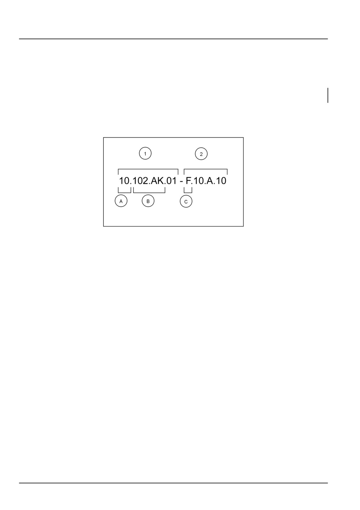
Engine block cover - Front - Remove (10.102.AP.01 - F.10.A.10)
unit
Information Unit SAP
10
102
AK
01
F
10.A.10
code
SAP code classification Engine
Pan and covers Engine block Front
Service data Remove
cover
NHIL12GEN0070A
1
Navigate to the correct information unit you are searching for by identifying the function and information type
from the SAP code.
•
(1) Location and (2) Information type.
•
(A) corresponds to the sections of the service manual.
(B) corresponds to the chapters of the service manual. After (B) there may be some additional information. In this
case it shows “.01”, which represents the “Front” block cover. These options may be front/rear, left/right, hydraulic/
mechanical etc.
(C) corresponds to the type of information listed in the chapter contents: Technical Data, Functional Data, Diagnos-
tic, or Service.
(A) and (B) are also shown in the page numbering on the page footer.
THE REST OF THE CODING IS NOT LISTED IN ALPHANUMERIC ORDER IN THIS MANUAL.
• You will find a table of contents at the beginning and end of each section and chapter.
You will find an alphabetical index at the end of each chapter.
• By referring to (A), (B) and (C) of the coding, you can follow the contents or index (page numbers) and quickly find
the information you are looking for.
Page header and footer
The page header will contain the following references:
• Section and Chapter description
The page footer will contain the following references:
• Publication number for that Manual.
• Version reference for that publication.
• Publication date
• Section, chapter, and page reference e.g. 10.102 / 9
47524331 18/04/2013
8
INTRODUCTION
Safety rules
Personal safety
This is the safety alert symbol. It is used to alert you to potential personal injury hazards. Obey all
safety messages that follow this symbol to avoid possible death or injury.
Throughout this manual and on machine decals, you will find the signal words DANGER, WARNING, and CAUTION
followed by special instructions. These precautions are intended for the personal safety of you and those working
with you.
Read and understand all the safety messages in this manual before you operate or service the machine.
DANGER indicates a hazardous situation which, if not avoided, will result in death or serious injury. The
color associated with DANGER is RED.
WARNING indicates a hazardous situation which, if not avoided, could result in death or serious injury.
The color associated with WARNING is ORANGE.
CAUTION, used with the safety alert symbol, indicates a hazardous situation which, if not avoided, could result
in minor or moderate injury. The color associated with CAUTION is YELLOW.
FAILURE TO FOLLOW DANGER, WARNING, AND CAUTION MESSAGES COULD RESULT
IN DEATH OR SERIOUS INJURY.
Machine safety
NOTICE: Notice indicates a situation which, if not avoided, could result in machine or property damage. The color
associated with Notice is BLUE.
Throughout this manual you will find the signal word Notice followed by special instructions to prevent machine or
property damage. The word Notice is used to address practices not related to personal safety.
Information
NOTE: Note indicates additional information which clarifies steps, procedures, or other information in this manual.
Throughout this manual you will find the word Note followed by additional information about a step, procedure, or
other information in the manual. The word Note is not intended to address personal safety or property damage.
47524331 18/04/2013
9

INTRODUCTION
Safety rules
WARNING
Equipment rolling hazard!
Firmly apply the handbrake and place the shuttle lever in the park brake position. Stop the engine
before leaving the machine. The transmission will not prevent the machine from rolling when the
engine is shut off.
Failure to comply could result in death or serious injury.
W0378A
WARNING
Improper operation or service of this machine can result in an accident.
Before working on any part of the electrical system, disconnect the battery ground cable. Complete
all electrical work before connecting the cable.
Failure to comply could result in death or serious injury.
W0137A
WARNING
Crushing hazard!
The wheels on this vehicle are very heavy. Always use a wheel remover or chain hoists to remove and
install the wheels. Use an assistant as required.
Failure to comply could result in death or serious injury.
W0149A
WARNING
Jack stands can slip or fall over. Dropping, tipping, or slipping of machine or its components is pos-
sible.
DO NOT work under a vehicle supported by jack stands only. Park machine on a level surface. Block
wheels. Support machine with safety stands.
Failure to comply could result in death or serious injury.
W0069A
WARNING
Fire hazard!
When handling diesel fuel, observe the following precautions:
1. Do not smoke.
2. Never fill the tank when the engine is running.
3. Wipe up spilled fuel immediately.
Failure to comply could result in death or serious injury.
W0099A
WARNING
Escaping fluid!
Hydraulic fluid or diesel fuel leaking under pressure can penetrate the skin and cause infection or
other injury. To prevent personal injury: Relieve all pressure before disconnecting fluid lines or per-
forming work on the hydraulic system. Before applying pressure, make sure all connections are tight
and all components are in good condition. Never use your hand to check for suspected leaks under
pressure. Use a piece of cardboard or wood for this purpose. If injured by leaking fluid, see your
doctor immediately.
Failure to comply could result in death or serious injury.
W0178A
WARNING
Fire hazard!
Do not add gasoline, alcohol, or blended fuels to diesel fuel, except as recommended in this manual.
Fuel combinations may increase fire and explosion hazards.
Failure to comply could result in death or serious injury.
W0401A
47524331 18/04/2013
10
INTRODUCTION
WARNING
Personal Protective Equipment (PPE) required.
When assembling, operating, or servicing the machine, wear protective clothing and PPE necessary
for the particular procedure. Some PPE that may be necessary includes protective shoes, eye and/or
face protection, hard hat, heavy gloves, filter mask, and hearing protection.
Failure to comply could result in death or serious injury.
W0353A
47524331 18/04/2013
11

INTRODUCTION
Torque - Minimum tightening torques for normal assembly
METRIC NON-FLANGED HARDWARE
NOM.
LOCKNUT
LOCKNUT
SIZE
CL.8
CL.10
CLASS 8.8 BOLT and
CLASS 10.9 BOLT and
W/CL8.8
W/CL10.9
CLASS 8 NUT
CLASS 10 NUT
BOLT
BOLT
PLATED
PLATED
UNPLATED
UNPLATED
W/ZnCr
W/ZnCr
2.2 N·m (19 lb
2.9 N·m (26 lb
3.2 N·m (28 lb
4.2 N·m (37 lb
2.9 N·m (26 lb
M4
2 N·m (18 lb in)
in)
in)
in)
in)
in)
4.5 N·m (40 lb
5.9 N·m (52 lb
6.4 N·m (57 lb
8.5 N·m (75 lb
5.8 N·m (51 lb
M5
4 N·m (36 lb in)
in)
in)
in)
in)
in)
7.5 N·m (66 lb
10 N·m (89 lb
11 N·m (96 lb
15 N·m (128 lb
6.8 N·m (60 lb
10 N·m (89 lb
M6
in)
in)
in)
in)
in)
in)
18 N·m (163 lb
25 N·m (217 lb
26 N·m (234 lb
35 N·m (311 lb
17 N·m (151 lb
24 N·m (212 lb
M8
in)
in)
in)
in)
in)
in)
49 N·m (36 lb
70 N·m (51 lb
33 N·m (25 lb
48 N·m (35 lb
M10
37 N·m (27 lb ft)
52 N·m (38 lb ft)
ft)
ft)
ft)
ft)
85 N·m (63 lb
121 N·m (90 lb
58 N·m (43 lb
83 N·m (61 lb
M12
64 N·m (47 lb ft)
91 N·m (67 lb ft)
ft)
ft)
ft)
ft)
158 N·m (116 lb
210 N·m (155
225 N·m (166 lb
301 N·m (222
143 N·m (106 lb
205 N·m (151 lb
M16
ft)
lb ft)
ft)
lb ft)
ft)
ft)
319 N·m (235 lb
425 N·m (313
440 N·m (325 lb
587 N·m (433
290 N·m (214 lb
400 N·m (295 lb
M20
ft)
lb ft)
ft)
lb ft)
ft)
ft)
551 N·m (410 lb
735 N·m (500
762 N·m (560 lb
1016 N·m (750
501 N·m (370 lb
693 N·m (510 lb
M24
ft)
lb ft)
ft)
lb ft)
ft)
ft)
NOTE: M4 through M8 hardware torque specifications are shown in pound-inches. M10 through M24 hardware torque
specifications are shown in pound-feet.
47524331 18/04/2013
12
INTRODUCTION
METRIC FLANGED HARDWARE
NOM.
CLASS 8.8
BOLT and
CLASS 10.9 BOLT and
LOCKNUT
LOCKNUT
SIZE
CLASS
8 NUT
CLASS 10 NUT
CL.8
CL.10
W/CL8.8
W/CL10.9
BOLT
BOLT
PLATED
PLATED
UNPLATED
UNPLATED
W/ZnCr
W/ZnCr
2.4 N·m (21 lb
3.2 N·m (28 lb
3.5 N·m (31 lb
4.6 N·m (41 lb
2.2 N·m (19 lb
3.1 N·m (27 lb
M4
in)
in)
in)
in)
in)
in)
4.9 N·m (43 lb
6.5 N·m (58 lb
7.0 N·m (62 lb
9.4 N·m (83 lb
4.4 N·m (39 lb
6.4 N·m (57 lb
M5
in)
in)
in)
in)
in)
in)
8.3 N·m (73 lb
11 N·m (96 lb
12 N·m (105 lb
16 N·m (141 lb
7.5 N·m (66 lb
11 N·m (96 lb
M6
in)
in)
in)
in)
in)
in)
20 N·m (179 lb
27 N·m (240 lb
29 N·m (257 lb
39 N·m (343 lb
18 N·m (163 lb
27 N·m (240 lb
M8
in)
in)
in)
in)
in)
in)
54 N·m (40 lb
77 N·m (56 lb
M10
40 N·m (30 lb ft)
57 N·m (42 lb ft)
37 N·m (27 lb ft)
53 N·m (39 lb ft)
ft)
ft)
93 N·m (69 lb
100 N·m (74 lb
134 N·m (98 lb
M12
70 N·m (52 lb ft)
63 N·m (47 lb ft)
91 N·m (67 lb ft)
ft)
ft)
ft)
174 N·m (128 lb
231 N·m (171
248 N·m (183 lb
331 N·m (244
158 N·m (116 lb
226 N·m (167 lb
M16
ft)
lb ft)
ft)
lb ft)
ft)
ft)
350 N·m (259 lb
467 N·m (345
484 N·m (357 lb
645 N·m (476
318 N·m (235 lb
440 N·m (325 lb
M20
ft)
lb ft)
ft)
lb ft)
ft)
ft)
607 N·m (447 lb
809 N·m (597
838 N·m (618 lb
1118 N·m (824
552 N·m (407 lb
M24
ft)
lb ft)
ft)
lb ft)
ft)
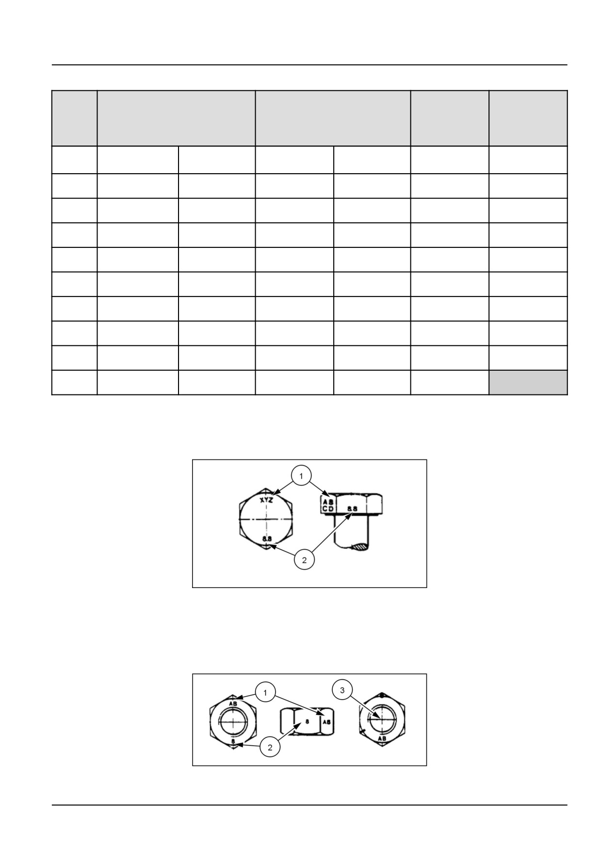
IDENTIFICATION
Metric Hex head and carriage bolts, classes 5.6 and up
20083680
1
1. Manufacturer's Identification
2. Property Class
Metric Hex nuts and locknuts, classes 05 and up
20083681
2
47524331 18/04/2013
13

INTRODUCTION
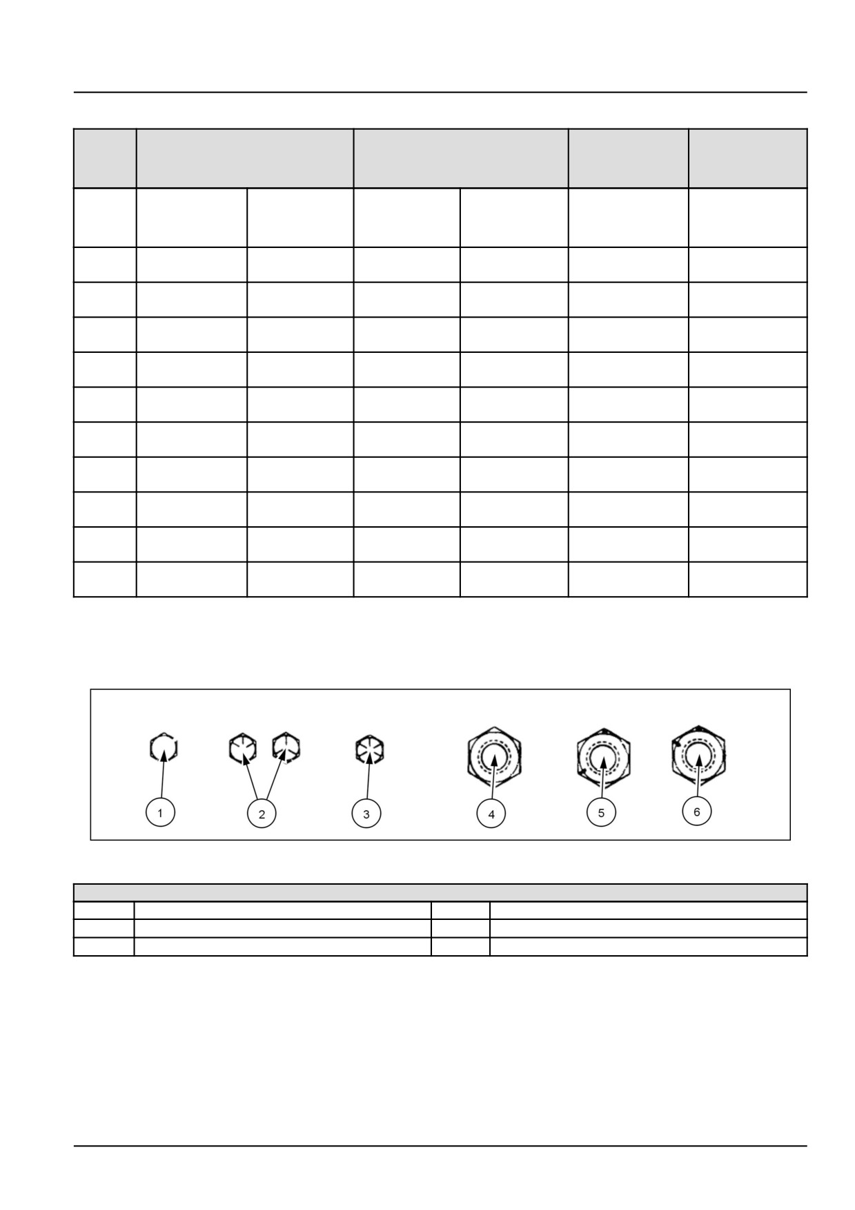
1. Manufacturer's Identification
2. Property Class
3. Clock Marking of Property Class and Manufacturer's Identification (Optional), i.e. marks 60 ° apart indicate Class
10 properties, and marks 120 ° apart indicate Class 8.
INCH NON-FLANGED HARDWARE
LOCKNUT
LOCKNUT
NOMINAL
SAE GRADE 5 BOLT
SAE GRADE 8 BOLT
GrB W/ Gr5
GrC W/ Gr8
SIZE
and NUT
and NUT
BOLT
BOLT
UN-
UN-
PLATED
PLATED
PLATED
PLATED
or
W/ZnCr
W/ZnCr
or PLATED
PLATED
GOLD
GOLD
SILVER
SILVER
8 N·m (71 lb
11 N·m (97 lb
12 N·m (106
16 N·m (142
12.2 N·m (109 lb
1/4
8.5 N·m (75 lb in)
in)
in)
lb in)
lb in)
in)
17 N·m (150
23 N·m (204
24 N·m (212
32 N·m (283
17.5 N·m (155 lb
25 N·m (220 lb
5/16
lb in)
lb in)
lb in)
lb in)
in)
in)
30 N·m (22 lb
40 N·m (30
43 N·m (31 lb
57 N·m (42 lb
3/8
31 N·m (23 lb ft)
44 N·m (33 lb ft)
ft)
lb ft)
ft)
ft)
48 N·m (36 lb
65 N·m (48
68 N·m (50 lb
91 N·m (67 lb
7/16
50 N·m (37 lb ft)
71 N·m (53 lb ft)
ft)
lb ft)
ft)
ft)
74 N·m (54 lb
98 N·m (73
104 N·m (77
139 N·m (103
1/2
76 N·m (56 lb ft)
108 N·m (80 lb ft)
ft)
lb ft)
lb ft)
lb ft)
107 N·m (79
142 N·m (105
150 N·m (111
201 N·m (148
156 N·m (115 lb
9/16
111 N·m (82 lb ft)
lb ft)
lb ft)
lb ft)
lb ft)
ft)
147 N·m (108
196 N·m (145
208 N·m (153
277 N·m (204
153 N·m (113 lb
215 N·m (159 lb
5/8
lb ft)
lb ft)
lb ft)
lb ft)
ft)
ft)
261 N·m (193
348 N·m (257
369 N·m (272
491 N·m (362
271 N·m (200 lb
383 N·m (282 lb
3/4
lb ft)
lb ft)
lb ft)
lb ft)
ft)
ft)
420 N·m (310
561 N·m (413
594 N·m (438
791 N·m (584
437 N·m (323 lb
617 N·m (455 lb
7/8
lb ft)
lb ft)
lb ft)
lb ft)
ft)
ft)
630 N·m (465
841 N·m (620
890 N·m (656
1187 N·m
654 N·m (483 lb
924 N·m (681 lb
1
lb ft)
lb ft)
lb ft)
(875 lb ft)
ft)
ft)
NOTE: For Imperial Units, 1/4 in and 5/16 in hardware torque specifications are shown in pound-inches.
3/8 in
through 1 in hardware torque specifications are shown in pound-feet.
47524331 18/04/2013
14
INTRODUCTION
INCH FLANGED HARDWARE
NOM-
LOCKNUT
LOCKNUT
SAE GRADE 5 BOLT and
SAE GRADE 8 BOLT and
INAL
GrF W/ Gr5
GrG W/ Gr8
NUT
NUT
SIZE
BOLT
BOLT
UNPLATED
PLATED
UNPLATED
PLATED
or PLATED
W/ZnCr
or PLATED
W/ZnCr
SILVER
GOLD
SILVER
GOLD
12 N·m (106 lb
13 N·m (115 lb
17 N·m (150 lb
12 N·m (106 lb
1/4
9 N·m (80 lb in)
8 N·m (71 lb in)
in)
in)
in)
in)
19 N·m (168 lb
25 N·m (221 lb
26 N·m (230 lb
35 N·m (310 lb
17 N·m (150 lb
24 N·m (212 lb
5/16
in)
in)
in)
in)
in)
in)
44 N·m (33 lb
47 N·m (35 lb
63 N·m (46 lb
3/8
33 N·m (25 lb ft)
30 N·m (22 lb ft)
43 N·m (32 lb ft)
ft)
ft)
ft)
71 N·m (52 lb
75 N·m (55 lb
100 N·m (74 lb
7/16
53 N·m (39 lb ft)
48 N·m (35 lb ft)
68 N·m (50 lb ft)
ft)
ft)
ft)
108 N·m (80 lb
115 N·m (85 lb
153 N·m (113
104 N·m (77 lb
1/2
81 N·m (60 lb ft)
74 N·m (55 lb ft)
ft)
ft)
lb ft)
ft)
117 N·m (86 lb
156 N·m (115
165 N·m (122
221 N·m (163
157 N·m (116 lb
9/16
106 N·m (78 lb ft)
ft)
lb ft)
lb ft)
lb ft)
ft)
162 N·m (119 lb
216 N·m (159
228 N·m (168
304 N·m (225
147 N·m (108 lb
207 N·m (153 lb
5/8
ft)
lb ft)
lb ft)
lb ft)
ft)
ft)
287 N·m (212 lb
383 N·m (282
405 N·m (299
541 N·m (399
261 N·m (193 lb
369 N·m (272 lb
3/4
ft)
lb ft)
lb ft)
lb ft)
ft)
ft)
462 N·m (341 lb
617 N·m (455
653 N·m (482
871 N·m (642
421 N·m (311 lb
594 N·m (438 lb
7/8
ft)
lb ft)
lb ft)
lb ft)
ft)
ft)
693 N·m (512 lb
925 N·m (682
979 N·m (722
1305 N·m (963
631 N·m (465 lb
890 N·m (656 lb
1
ft)
lb ft)
lb ft)
lb ft)
ft)
ft)
IDENTIFICATION
Inch Bolts and free-spinning nuts
20083682
3
Grade Marking Examples
SAE Grade Identification
1
Grade 2 - No Marks
4
Grade 2 Nut - No Marks
2
Grade 5 - Three Marks
5
Grade 5 Nut - Marks 120 ° Apart
3
Grade 8 - Five Marks
6
Grade 8 Nut - Marks 60 ° Apart
47524331 18/04/2013
15
INTRODUCTION
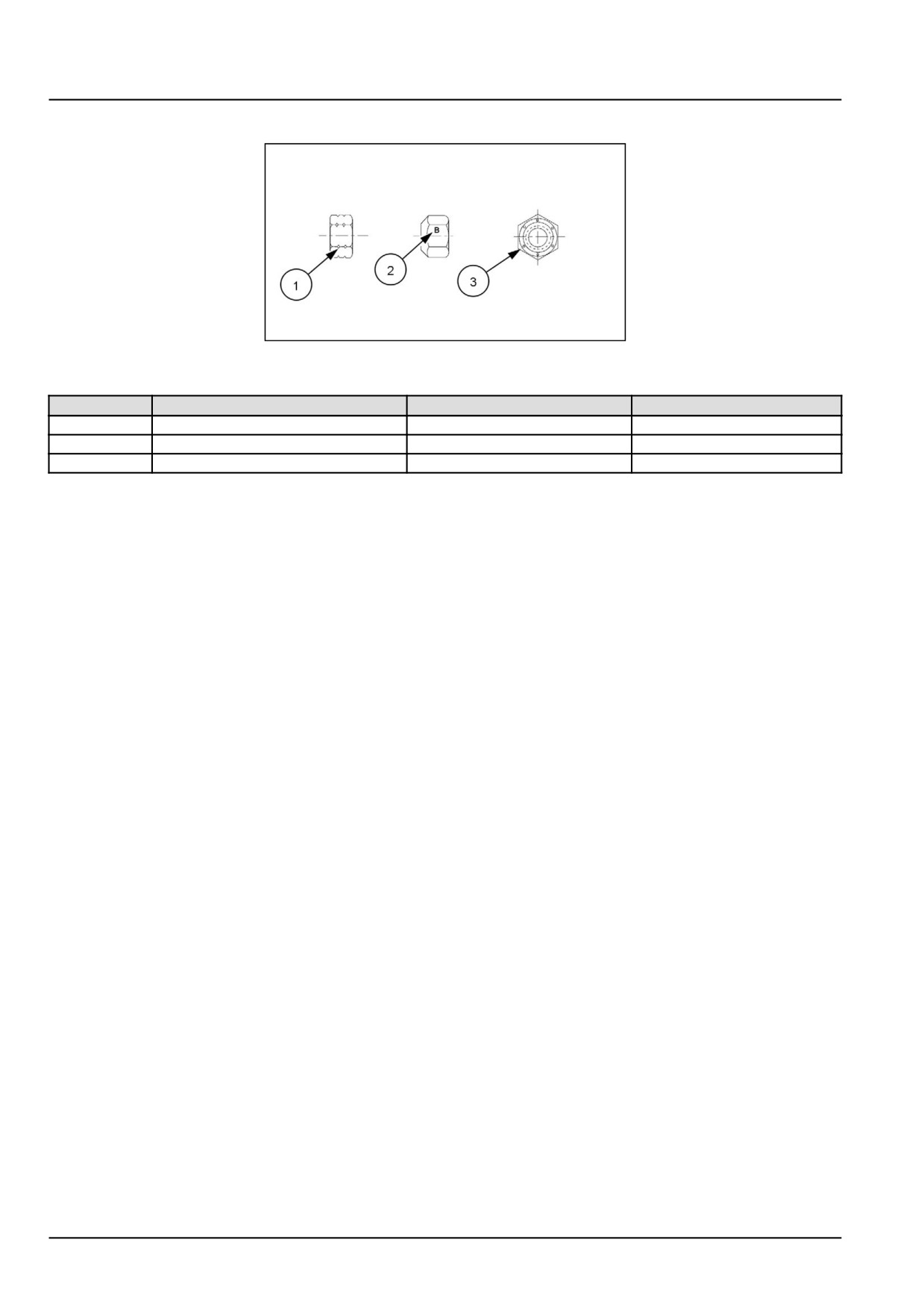
Inch Lock Nuts, All Metal (Three optional methods)
20090268
4
Grade Identification
Grade
Corner Marking Method (1)
Flats Marking Method (2)
Clock Marking Method (3)
Grade A
No Notches
No Mark
No Marks
Grade B
One Circumferential Notch
Letter B
Three Marks
Grade C
Two Circumferential Notches
Letter C
Six Marks
47524331 18/04/2013
16
INTRODUCTION
Torque - Standard torque data for hydraulics
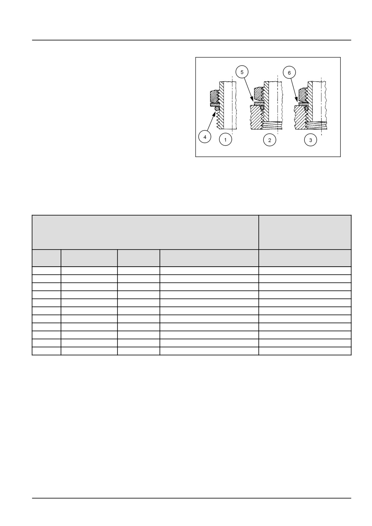
INSTALLATION OF ADJUSTABLE FITTINGS
IN STRAIGHT THREAD O RING BOSSES
1. Lubricate the O-ring by coating it with a light oil or
petroleum. Install the O-ring in the groove adjacent
to the metal backup washer which is assembled at the
extreme end of the groove (4).
2. Install the fitting into the SAE straight thread boss until
the metal backup washer contacts the face of the boss
(5).
NOTE: Do not over tighten and distort the metal
backup washer.
23085659
1
3. Position the fitting by turning out (counterclockwise)
up to a maximum of one turn. Holding the pad of the
fitting with a wrench, tighten the locknut and washer
against the face of the boss (6).
STANDARD TORQUE DATA FOR HYDRAULIC TUBES AND FITTINGS
TUBE NUTS FOR 37° FLARED FITTINGS
O-RING BOSS PLUGS
ADJUSTABLE FITTING
LOCKNUTS, SWIVEL
JIC- 37° SEATS
SIZE
TUBING OD
THREAD
TORQUE
TORQUE
SIZE
4
6.4 mm (1/4 in)
7/16-20
12 - 16 N·m (9 - 12 lb ft)
8 - 14 N·m (6 - 10 lb ft)
5
7.9 mm (5/16 in)
1/2-20
16 - 20 N·m (12 - 15 lb ft)
14 - 20 N·m (10 - 15 lb ft)
6
9.5 mm (3/8 in)
9/16-18
29 - 33 N·m (21 - 24 lb ft)
20 - 27 N·m (15 - 20 lb ft)
8
12.7 mm (1/2 in)
3/4-16
47 - 54 N·m (35 - 40 lb ft)
34 - 41 N·m (25 - 30 lb ft)
10
15.9 mm (5/8 in)
7/8-14
72 - 79 N·m (53 - 58 lb ft)
47 - 54 N·m (35 - 40 lb ft)
12
19.1 mm (3/4 in)
1-1/16-12
104 - 111 N·m (77 - 82 lb ft)
81 - 95 N·m (60 - 70 lb ft)
14
22.2 mm (7/8 in)
1-3/16-12
122 - 136 N·m (90 - 100 lb ft)
95 - 109 N·m (70 - 80 lb ft)
16
25.4 mm (1 in)
1-5/16-12
149 - 163 N·m (110 - 120 lb ft)
108 - 122 N·m (80 - 90 lb ft)
20
31.8 mm (1-1/4 in)
1-5/8-12
190 - 204 N·m (140 - 150 lb ft)
129 - 158 N·m (95 - 115 lb ft)
24
38.1 mm (1-1/2 in)
1-7/8-12
217 - 237 N·m (160 - 175 lb ft)
163 - 190 N·m (120 - 140 lb ft)
32
50.8 mm (2 in)
2-1/2-12
305 - 325 N·m (225 - 240 lb ft)
339 - 407 N·m (250 - 300 lb ft)
These torques are not recommended for tubes of 12.7 mm (1/2 in) OD and larger with wall thickness of 0.889 mm
(0.035 in) or less. The torque is specified for 0.889 mm (0.035 in) wall tubes on each application individually.
Before installing and torquing 37 ° flared fittings, clean the face of the flare and threads with a clean solvent or Loctite
cleaner and apply hydraulic sealant LOCTITE® 569 to the 37 ° flare and the threads.
Install fitting and torque to specified torque, loosen fitting and retorque to specifications.
47524331 18/04/2013
17
INTRODUCTION
PIPE THREAD FITTING TORQUE
PIPE THREAD FITTING
Thread Size
Torque (Maximum)
Before installing and tightening pipe fittings, clean the
1/8-27
13 N·m (10 lb ft)
threads with a clean solvent or Loctite cleaner and apply
1/4-18
16 N·m (12 lb ft)
sealant LOCTITE® 567 PST PIPE SEALANT for all fittings
including stainless steel or LOCTITE® 565 PST for most
3/8-18
22 N·m (16 lb ft)
metal fittings. For high filtration/zero contamination sys-
1/2-14
41 N·m (30 lb ft)
tems use LOCTITE® 545.
3/4-14
54 N·m (40 lb ft)
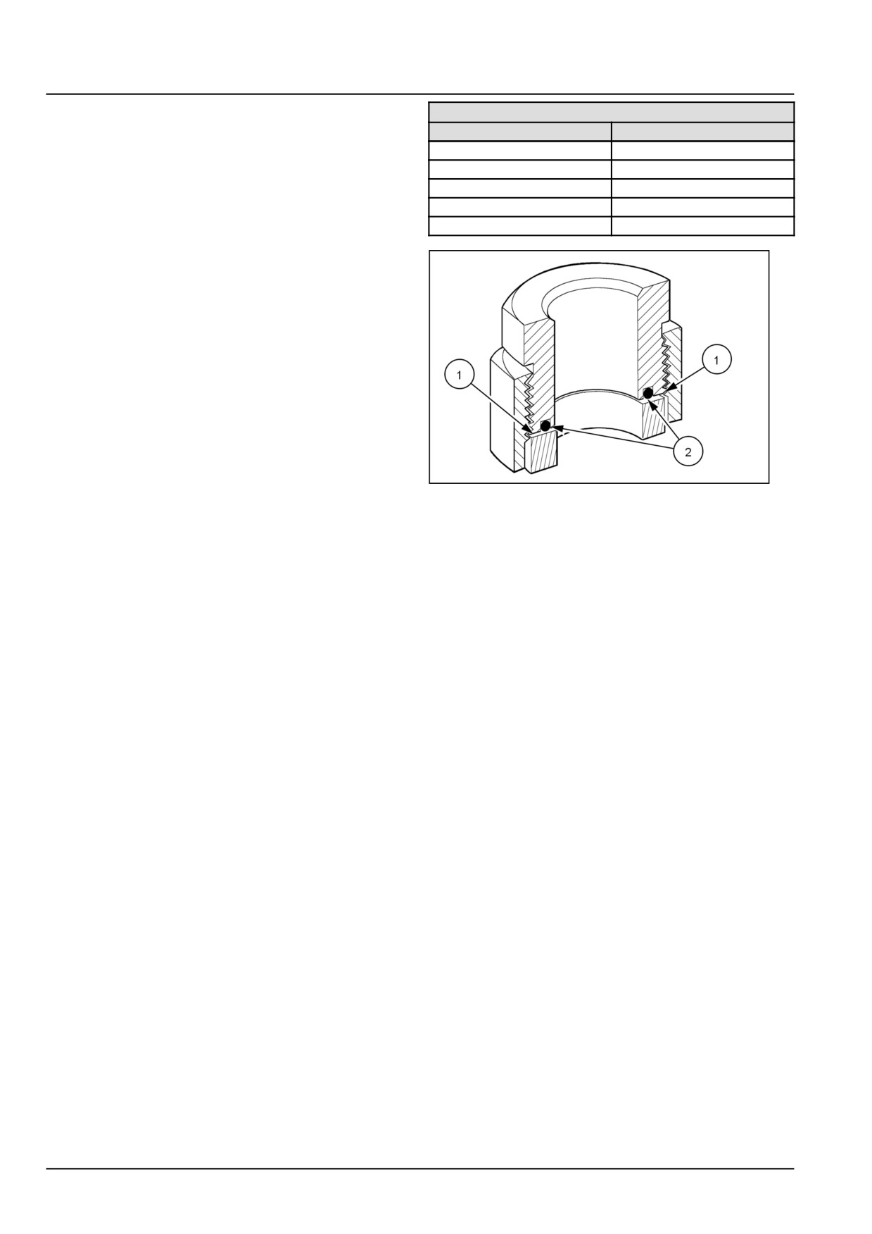
INSTALLATION OF ORFS (O-RING FLAT
FACED) FITTINGS
When installing ORFS fittings thoroughly clean both flat
surfaces of the fittings (1) and lubricate the O-ring (2) with
light oil. Make sure both surfaces are aligned properly.
Torque the fitting to specified torque listed throughout the
repair manual.
NOTICE: If the fitting surfaces are not properly cleaned,
the O-ring will not seal properly. If the fitting surfaces are
not properly aligned, the fittings may be damaged and will
not seal properly.
NOTICE: Always use genuine factory replacement oils
50011183
2
and filters to ensure proper lubrication and filtration of en-
gine and hydraulic system oils.
The use of proper oils, grease, and keeping the hydraulic
system clean will extend machine and component life.
47524331 18/04/2013
18
INTRODUCTION
General specification - Biodiesel Fuels
Fatty Acid Methyl Ester Biodiesel (Biodiesel Fuel) consists of a family of fuels derived from vegetable oils treated with
methyl esters.
NOTICE: Biodiesel Fuel blends are approved for your engine only if they comply with EN14214 Specification Stan-
dards or ASTM D6751.
NOTICE: It is imperative that you check which blend is approved for your engine with your New Holland dealer. Be
aware that the use of Biodiesel Fuel that does not comply with the Standards mentioned above could lead to severe
damage to the engine and fuel system of your machine. The use of fuels that are not approved may void NEW
HOLLAND AGRICULTURE Warranty coverage.
Biodiesel Fuel Usage Conditions
NOTICE: The Biodiesel Fuel must meet the fuel Specification mentioned above.
Biodiesel Fuel must be purchased from a trusted supplier that understands the product and maintains good fuel qual-
ity. Biodiesel Fuel must be pre-blended by the supplier. Mixing Biodiesel Fuels on-site can result incorrect mixture
that can lead to problems with both engine and fuel system.
Engine performance is affected by the use of Biodiesel Fuel. There may be up to 12 % reduction in power or torque
depending on the blend used.
NOTICE: DO NOT modify the engine and/or injection pump settings to recover the reduced performance.
The reduced power must be accepted if using any Biodiesel Fuel blend.
Some modification may be required to allow your engine to run Biodiesel Fuel. Consult you dealer for complete
information on these modifications.
Biodiesel Fuel has a higher cloud point than Diesel Fuel.
NOTICE: The use of high Biodiesel Fuel blends are not recommended in cold weather conditions.
With Biodiesel Fuels, it may be necessary to change the engine oil, engine oil filter and fuel filter elements more
frequently than with Diesel Fuels. Biodiesel Fuel can remove rust and particles from the inside of on-site fuel storage
tanks that would normally adhere to the sides of the tank. Like particle deposits that commonly occur with Diesel Fuel,
these particles can become trapped by the machine fuel filters, causing blockage and shortening filter life. In cold
weather, this is more likely to happen. Consult your New Holland dealer for information on cold weather operation
and proper maintenance intervals when using any Biodiesel Fuel blend.
When handling Biodiesel Fuel, care must be taken not to allow water into the fuel supply. Biodiesel Fuel will actually
attract moisture from the atmosphere.
Fuel tanks must be kept as full as possible to limit the amount of air and water vapors in them. It may be necessary
to drain the fuel filter water tap more frequently.
Potential oxidation and stability could be a problem with the fuel stored in the machine.
NOTICE: Machines must not be stored for more than three months with Biodiesel Fuel blends in the fuel system.
If long storage periods are necessary, the engine must run on Diesel Fuel for 20 hours to flush the Biodiesel Fuel out
of the engine fuel system prior to storage.
NOTICE: Biodiesel Fuel must not be stored in on-site storage tanks for more than three months.
Any spillage of Biodiesel Fuel must be cleaned up immediately before it can cause damage to the environment and
the paint finish of the machine.
Before using Biodiesel Fuel blends you should consult with your dealer to receive full information about the approved
blend for your machine and any detailed conditions of its usage.
NOTICE: Be aware that not fulfilling the requirements and conditions of Biodiesel Fuel usage will void your machine’s
New Holland Warranty coverage.
47524331 18/04/2013
19
INTRODUCTION
Capacities
T7.220-270 AutoCommand, T7.220-260 Power Command
T7.220, T7.235, T7.250, T7.260
FUEL TANK (Less ABS models)
395 l (104.3 US gal)
DEF/ AdBlue® TANK (Less ABS models)
48 l (12.7 US gal)
FUEL TANK (With ABS models)
365 l (96.4 US gal)
DEF/ AdBlue® TANK (With ABS models)
53 l (14.0 US gal)
COOLING SYSTEM
22.5 l (5.9 US gal)
ENGINE (including filter)
15 l (3.96 US gal)
TRANSMISSION / REAR AXLE / HYDRAULICS
Power Command
82 l (21.7 US gal)
4WD FRONT AXLE - DIFFERENTIAL
11 l (11.6 US qt)
4WD FRONT HUBS
2.3 l (2.4 US qt)
(Class 4 Axle - less brakes)
4WD FRONT HUBS
3.8 l (4.0 US qt)
(Class 4 Axle - with brakes)
FRONT P.T.O.
3.05 l (3.2 US qt)
T7.220, T7.235, T7.250, T7.260, T7.270
FUEL TANK (Less ABS models)
395 l (104.3 US gal)
DEF/ AdBlue® TANK (Less ABS models)
48 l (12.7 US gal)
FUEL TANK (With ABS models)
354 l (93.5 US gal)
DEF/ AdBlue® TANK (With ABS models)
53 l (14.0 US gal)
COOLING SYSTEM
22.5 l (5.9 US gal)
ENGINE (including filter)
15 l (3.96 US gal)
TRANSMISSION / REAR AXLE / HYDRAULICS
CVT Transmission
84 l (22.2 US gal)
4WD FRONT AXLE - DIFFERENTIAL
11 l (11.6 US qt)
4WD FRONT HUBS
2.3 l (2.4 US qt)
(Class 4 Axle - less brakes)
4WD FRONT HUBS
3.8 l (4.0 US qt)
(Class 4 Axle - with brakes)
FRONT P.T.O.
3.05 l (3.2 US qt)
47524331 18/04/2013
20
INTRODUCTION
Consumables Lubrications and Coolants
Lubrications
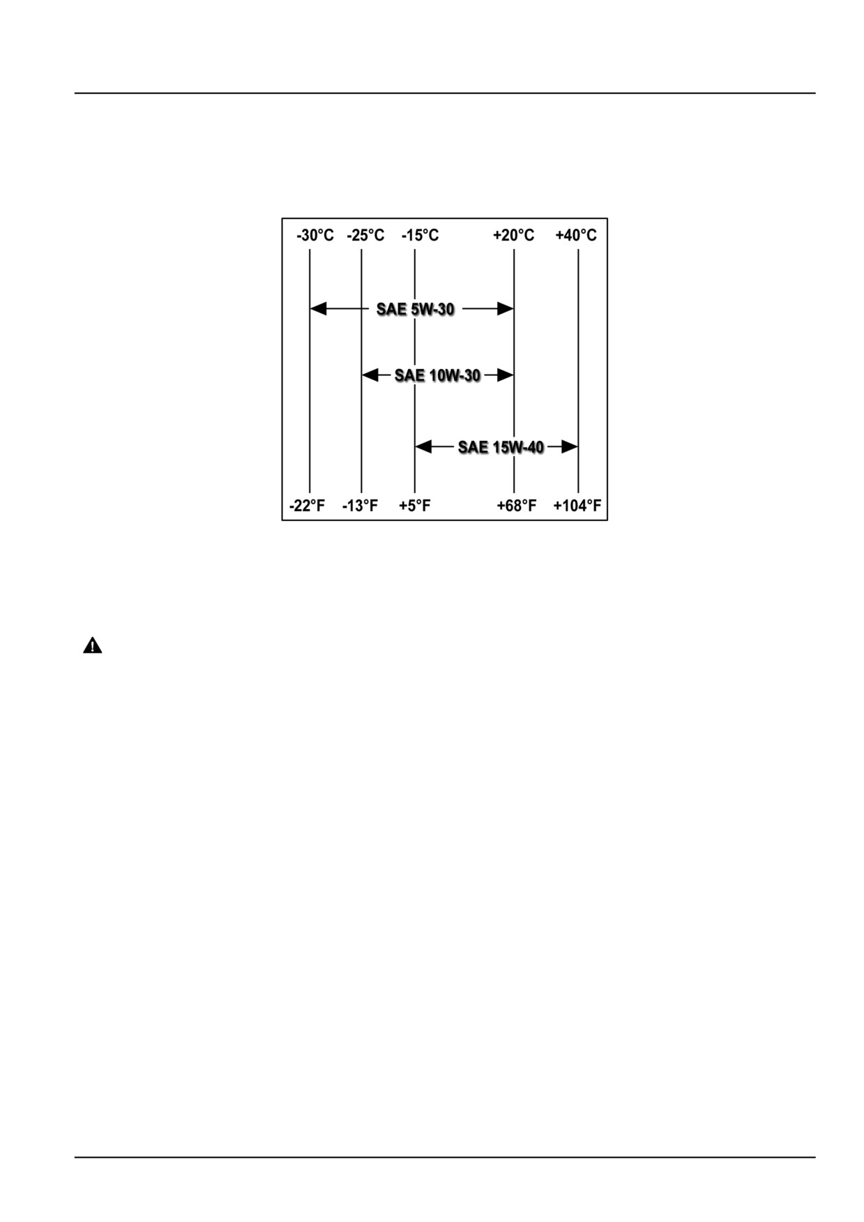
The correct engine oil viscosity grade is dependent upon ambient temperature. Refer to the chart when selecting oil
for your tractor engine.
SS09J076
1
NOTE: In areas where prolonged periods of extreme temperatures are encountered, local lubricant practices are
acceptable; such as the use of SAE 5W-30 in extreme low temperatures or SAE 50 in extreme high temperatures.
Biodegradable Transmission and Hydraulic Oil
WARNING
Burn hazard!
Be very careful to avoid contact with hot fluids. If fluid is extremely hot, allow it to cool to a moderately
warm temperature before proceeding.
Failure to comply could result in death or serious injury.
W0362A
A biodegradable oil has been approved for use in the transmission, 4WD front axle and hubs, and the hydraulic system
of your tractor. Although the oil is 90 % biodegradable, it is important to follow safe handling and disposal practices.
The NEW HOLLAND AMBRA MULTI BIO oil is available from your authorised dealer.
Biodegradable oil should not be used in conjunction with other oils. Use the following procedure to replace standard
oil with biodegradable lubricant.
1. Operate the tractor until the oil that is being changed reaches a temperature greater than 60 °C (140 °F).
2. Stop the engine and immediately drain the oil.
3. Replace all transmission and hydraulic filters.
4. Add the biodegradable oil to the correct level and run the tractor to circulate the oil.
5. Check for oil leaks and recheck the oil level.
Sulphur in Fuel
The engine oil and filter change period are shown in the Lubrication and Maintenance in the operators manual. How-
ever, locally available fuel may have a high sulphur content, in which case the engine oil and filter change period
should be adjusted as follows:
47524331 18/04/2013
21

INTRODUCTION
Sulphur Content
Oil Change Period
Below 0.5 %
Normal
From 0.5 - 1.0 %
Half the normal
Above 1.0 %
One quarter normal
NOTE: The use of fuel with a sulphur content above 1.3 % is not recommended.
Coolants
WARNING
Hazardous chemicals!
Chemical agent may be harmful.
-Avoid contact with eyes, and prolonged/repeated skin contact.
-Wear protective goggles when handling.
-Eye contact: Flush with water for 15 minutes. Seek immediate medical assistance.
-Wash skin with soap and water after handling.
-Keep out of reach of children.
Failure to comply could result in death or serious injury.
W0370A
To reduce the amount of deposits and corrosion, the water used in the cooling system must comply with the following
values.
Total Hardness
Chloride
Sulphate
300 parts per million
100 parts per million
100 parts per million
Using Plain water
If you reside in a country where antifreeze is not available, use clean water premixed with 5 % chemical inhibitor. The
inhibitor is available from your authorised dealer.
Lubrications and Coolant Specifications
NH
INTERNATIONAL
RECOMMENDED FLUIDS AND APPLICATIONS
SPECIFICATION
SPECIFICATION
RECOMMENDED ENGINE OIL
NEW HOLLAND AMBRA UNITEK CJ-4 ENGINE OIL SAE
10W-40
NEW HOLLAND AMBRA UNITEK CJ-4 ENGINE OIL SAE
MS 3521
API CJ-4
15W-40
NEW HOLLAND AMBRA UNITEK CJ-4 ENGINE OIL SAE
0W-40
ALTERNATIVE ENGINE OIL
NEW HOLLAND AMBRA MASTERGOLD™ HSP ENGINE OIL
SAE 15W-40
NH 330 H;
API CI-4,
NEW HOLLAND AMBRA MASTERGOLD™ HSP ENGINE OIL
NH 324 H
ACEA E7
SAE 10W-30
TRANSMISSION, REAR AXLE AND HYDRAULIC
SYSTEM OIL
NEW HOLLAND AMBRA MULTI G™ HYDRAULIC
TRANSMISSION OIL
API GL4
FRONT AXLE (Axle and Hubs)
NH 410 B
(SAE 10W-30)
NEW HOLLAND AMBRA MULTI G™ HYDRAULIC
(ISO VG32/46)
TRANSMISSION OIL
FRONT P.T.O GEARBOX OIL
NEW HOLLAND AMBRA MULTI G™ HYDRAULIC
TRANSMISSION OIL
ENGINE RADIATOR COOLANT
NEW HOLLAND AMBRA AGRIFLU
NH 900 A
Ethylene Glycol
(mixed with 50% of water)
47524331 18/04/2013
22

INTRODUCTION
NH
INTERNATIONAL
RECOMMENDED FLUIDS AND APPLICATIONS
SPECIFICATION
SPECIFICATION
BRAKE OIL
NEW HOLLAND AMBRA BRAKE LHM
NH 610 A
ISO 7308
AIR CONDITIONING COMPRESSOR OIL
PAG-E13
Low Viscosity Oil SP10
n/a
ISO100 Viscosity
GREASE FITTINGS AND BEARINGS
NEW HOLLAND AMBRA GR-9 MULTI-PURPOSE GREASE
NH 710 A
NLGI 2
Regarding filling quantity - see Capacities () .
47524331 18/04/2013
23
CONSUMABLES INDEX
Consumable
Reference
PAGE
Loctite® 569
Torque - Standard torque data for hydraulics
17
Loctite® 567 PST Pipe
Torque - Standard torque data for hydraulics
18
Sealant
Loctite® 565 PST
Torque - Standard torque data for hydraulics
18
Loctite® 545
Torque - Standard torque data for hydraulics
18
NEW HOLLAND Ambra
Consumables Lubrications and Coolants
21
MULTI BIO
NEW HOLLAND Ambra
Consumables Lubrications and Coolants
22
Unitek CJ-4 engine oil SAE
10W-40
NEW HOLLAND Ambra
Consumables Lubrications and Coolants
22
Unitek CJ-4 engine oil SAE
15W-40
NEW HOLLAND Ambra
Consumables Lubrications and Coolants
22
Unitek CJ-4 engine oil SAE
0W-40
NEW HOLLAND Ambra
Consumables Lubrications and Coolants
22
Mastergold™ HSP Engine oil
SAE 15W-40
NEW HOLLAND Ambra
Consumables Lubrications and Coolants
22
Mastergold™ HSP Engine oil
SAE 10W-30
NEW HOLLAND Ambra
Consumables Lubrications and Coolants
22
MULTI G™ hydraulic
transmission oil
NEW HOLLAND Ambra
Consumables Lubrications and Coolants
22
MULTI G™ hydraulic
transmission oil
NEW HOLLAND Ambra
Consumables Lubrications and Coolants
22
MULTI G™ hydraulic
transmission oil
NEW HOLLAND Ambra
Consumables Lubrications and Coolants
22
Agriflu
NEW HOLLAND Ambra Brake
Consumables Lubrications and Coolants
23
LHM
NEW HOLLAND Ambra GR-9
Consumables Lubrications and Coolants
23
Multi-purpose grease
47524331 18/04/2013
24
SERVICE MANUAL
Engine
T7.220 AutoCommand , T7.220 Power Command , T7.235 AutoCommand ,
T7.235 Power Command , T7.250 AutoCommand , T7.250 Power Command ,
T7.260 AutoCommand , T7.260 Power Command , T7.270 AutoCommand
47524331 18/04/2013
10
Contents
Engine - 10
[10.001] Engine and crankcase
10.1
T7.220 AutoCommand , T7.220 Power Command , T7.235 AutoCommand , T7.235 Power Command , T7.250 AutoCommand , T7.250
Power Command , T7.260 AutoCommand , T7.260 Power Command , T7.270 AutoCommand
[10.102] Pan and covers
10.2
T7.220 AutoCommand , T7.220 Power Command , T7.235 AutoCommand , T7.235 Power Command , T7.250 AutoCommand , T7.250
Power Command , T7.260 AutoCommand , T7.260 Power Command , T7.270 AutoCommand
[10.216] Fuel tanks
10.3
T7.220 AutoCommand , T7.220 Power Command , T7.235 AutoCommand , T7.235 Power Command , T7.250 AutoCommand , T7.250
Power Command , T7.260 AutoCommand , T7.260 Power Command , T7.270 AutoCommand
[10.210] Lift pump and lines
10.4
T7.220 AutoCommand , T7.220 Power Command , T7.235 AutoCommand , T7.235 Power Command , T7.250 AutoCommand , T7.250
Power Command , T7.260 AutoCommand , T7.260 Power Command , T7.270 AutoCommand
[10.218] Fuel injection system
10.5
T7.220 AutoCommand , T7.220 Power Command , T7.235 AutoCommand , T7.235 Power Command , T7.250 AutoCommand , T7.250
Power Command , T7.260 AutoCommand , T7.260 Power Command , T7.270 AutoCommand
[10.250] Turbocharger and lines
10.6
T7.220 AutoCommand , T7.220 Power Command , T7.235 AutoCommand , T7.235 Power Command , T7.250 AutoCommand , T7.250
Power Command , T7.260 AutoCommand , T7.260 Power Command , T7.270 AutoCommand
[10.254] Intake and exhaust manifolds and muffler
10.7
T7.220 AutoCommand , T7.220 Power Command , T7.235 AutoCommand , T7.235 Power Command , T7.250 AutoCommand , T7.250
Power Command , T7.260 AutoCommand , T7.260 Power Command , T7.270 AutoCommand
[10.500] Selective Catalytic Reduction (SCR) exhaust treatment
10.8
T7.220 AutoCommand , T7.220 Power Command , T7.235 AutoCommand , T7.235 Power Command , T7.250 AutoCommand , T7.250
Power Command , T7.260 AutoCommand , T7.260 Power Command , T7.270 AutoCommand
[10.400] Engine cooling system
10.9
T7.220 AutoCommand , T7.220 Power Command , T7.235 AutoCommand , T7.235 Power Command , T7.250 AutoCommand , T7.250
Power Command , T7.260 AutoCommand , T7.260 Power Command , T7.270 AutoCommand
[10.414] Fan and drive
10.10
T7.220 AutoCommand , T7.220 Power Command , T7.235 AutoCommand , T7.235 Power Command , T7.250 AutoCommand , T7.250
Power Command , T7.260 AutoCommand , T7.260 Power Command , T7.270 AutoCommand
[10.408] Oil cooler and lines
10.11
T7.220 AutoCommand , T7.220 Power Command , T7.235 AutoCommand , T7.235 Power Command , T7.250 AutoCommand , T7.250
Power Command , T7.260 AutoCommand , T7.260 Power Command , T7.270 AutoCommand
47524331 18/04/2013
10
CONSUMABLES INDEX
Consumable
Reference
PAGE
DEF/AdBlue®
Fuel tank - Remove
10.3 / 20
AMBRA AGRIFLU
Engine cooling system - Filling
10.9 / 4
47524331 18/04/2013
10
47524331 18/04/2013
10
Engine - 10
Engine and crankcase - 001
T7.220 AutoCommand , T7.220 Power Command , T7.235 AutoCommand ,
T7.235 Power Command , T7.250 AutoCommand , T7.250 Power Command ,
T7.260 AutoCommand , T7.260 Power Command , T7.270 AutoCommand
47524331 18/04/2013
10.1 [10.001] / 1
Contents
Engine - 10
Engine and crankcase - 001
TECHNICAL DATA
Engine
General specification
3
Special tools
3
SERVICE
Engine
Electrical test using DATAR equipment
4
Disconnect
7
Connect
22
Remove
36
Install
51
DIAGNOSTIC
Engine
Troubleshooting
66
47524331 18/04/2013
10.1 [10.001] / 2

Engine - Engine and crankcase
Engine - General specification
ATTENTION: For complete service information of engine block and components refer to the relevant Engine repair
manual
F4DFE613L*A
F4DFE613K*A
F4DFE613J*A
F4DFE613H*A
F4DFE613G*A
Engine - Special tools
No. TOOL
NAME
380000979
Puller for engine injection pump union gear
380000665
Tool to extract crankshaft front seal
380000663
Tool to extract crankshaft rear seal
380001099
Injector extractor
380000666
Crankshaft front seal installer
380000664
Crankshaft rear seal installer
380000988
Flywheel locking adaptor plate (to be used with
380000732)
380000732
Engine turning tool (to be used with 380000988)
380000667
Drift for camshaft bushing disassembly and reassembly
380000158
Torque screwdriver for injector solenoid valve connector
nut setting
99395363
Connecting rod bush squaring kit
380000301
Engine stand (revolving)
380001073
Engine lifting brackets
380040228
Large frame tractor splitting stand
47524331 18/04/2013
10.1 [10.001] / 3
Engine - Engine and crankcase
Engine - Electrical test using DATAR equipment
The engine controller uses the cam and crank sensor information to control the fuelling and injection timing. At initial
engine start, the sensor information is used to inform the controller when to initiate first injection. The sensor infor-
mation is also used by the controller to measure the actual engine speed. The crankshaft and camshaft sensors are
both inductive sensors which detect the rotation of the tone wheel. The signal produced must be a clean sine-wave
signal without any noise, disturbance or interferences.
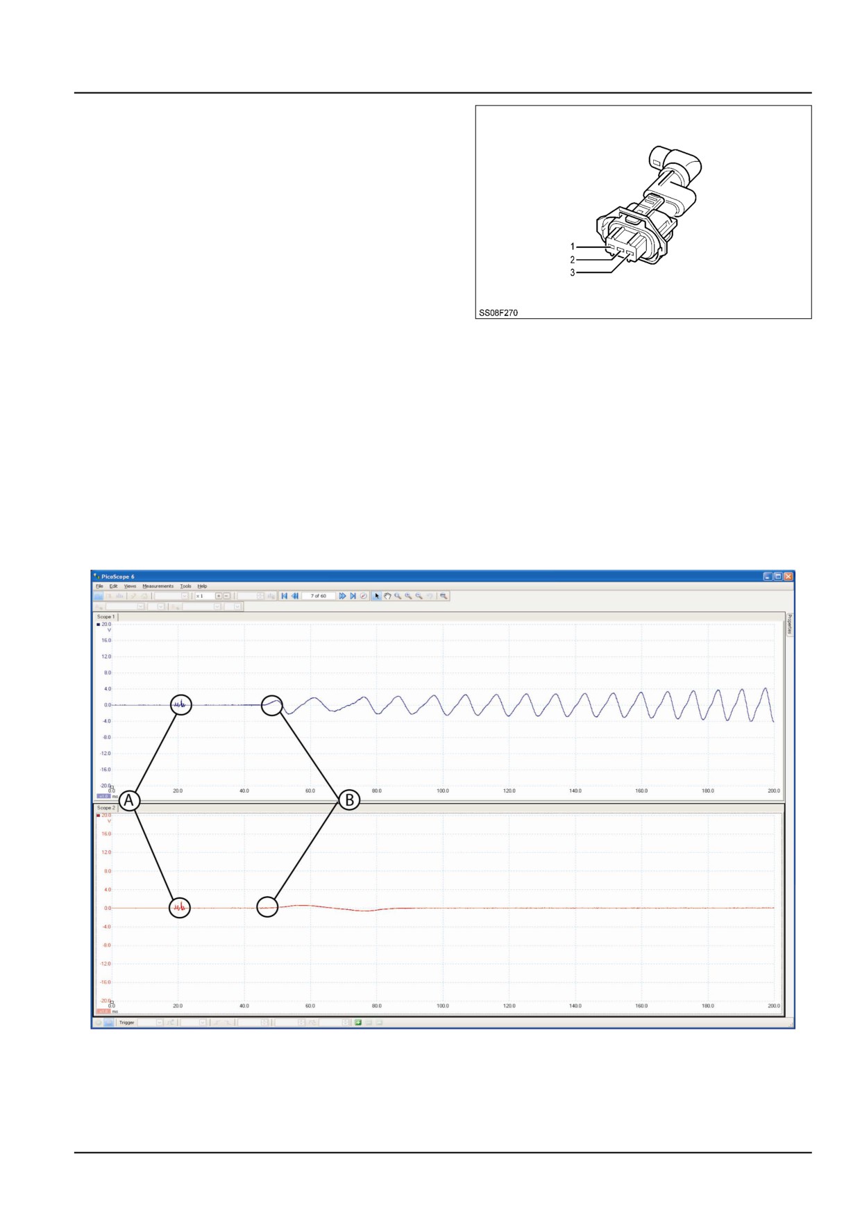
• Channel A (Blue)
Crankshaft, produces a sine-wave signal ranging ± 20 V. The amplitude
(voltage) will change depending on the engine speed.
• Channel B (Red)
Camshaft, produces a sine-wave signal.
1.
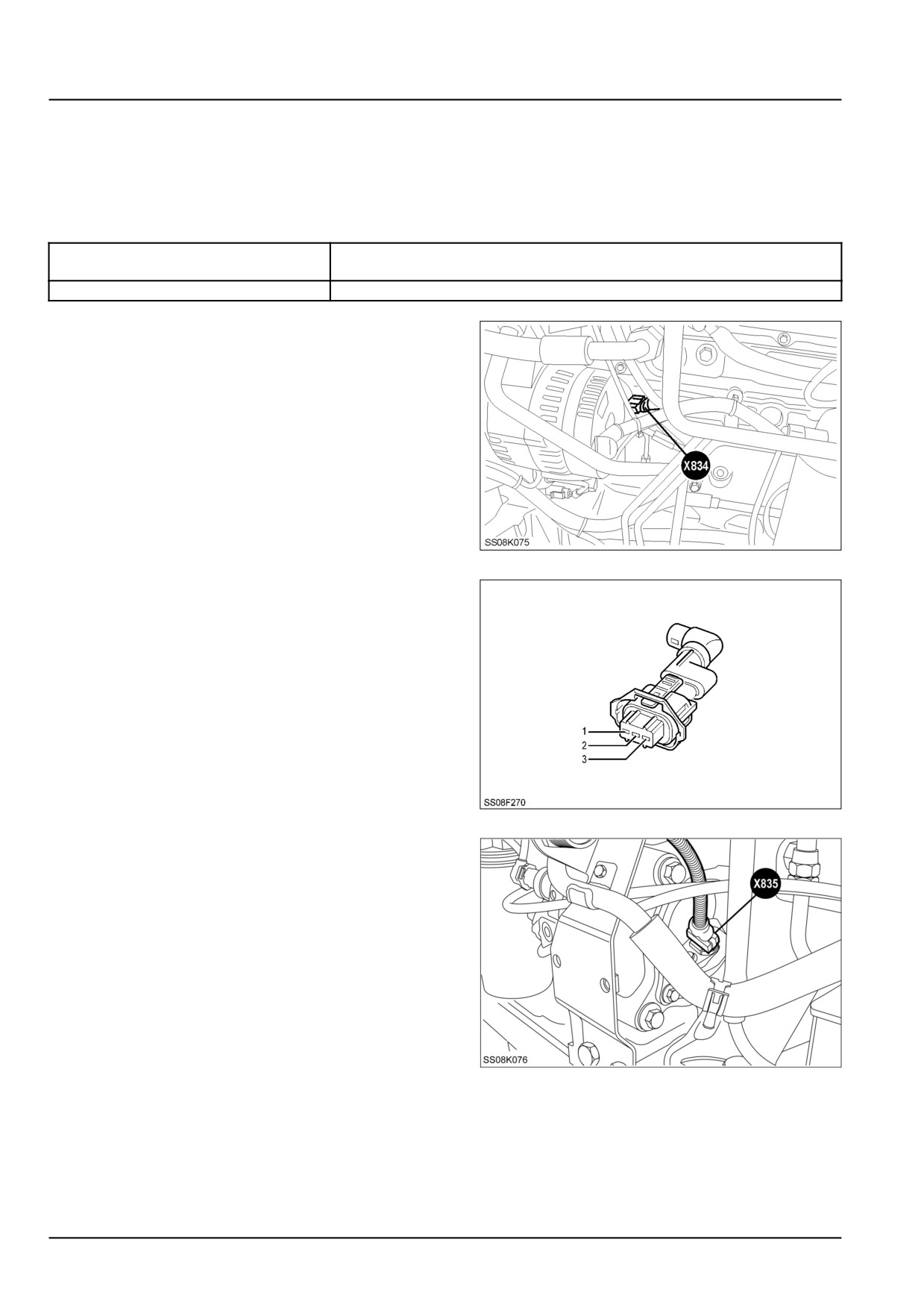
There are three wires to the crankshaft sensor X834
(located at the front left hand side of the engine
SS08K075
1
1.
Pin 1 : Earth
2.
Pin 2 : Signal
3.
Pin 3 : Power
SS08F270
2
2.
The camshaft sensor is connected at X835 with three
wires (located at the rear left hand side of the engine.
SS08K076
3
47524331 18/04/2013
10.1 [10.001] / 4
Engine - Engine and crankcase
1.
Pin 1 : Earth
2.
Pin 2 : Signal
3.
Pin 3 : Power
SS08F270
4
3.
Slide the back-pin down into the connector PIN 2
signal line so that the signal can be tested.
4.
Connect the DATAR Scope using the test leads by
inserting the red lead into the back-pin and connect-
ing the black lead onto the Earth.
the Channel A (Blue) to test the crank to ×1 @ ± 20
V
Set the Channel B (Red) to test the cam to ×1 @ ±
20 V
Collection time = 20 ms per division.
Results
BAIL11CVT088FMA
5
Engine start up
Figure 5
(A) = Ignition start up
(B) = Engine begins to turn
47524331 18/04/2013
10.1 [10.001] / 5
Engine - Engine and crankcase
BAIL10CVT054FMB
6
5.
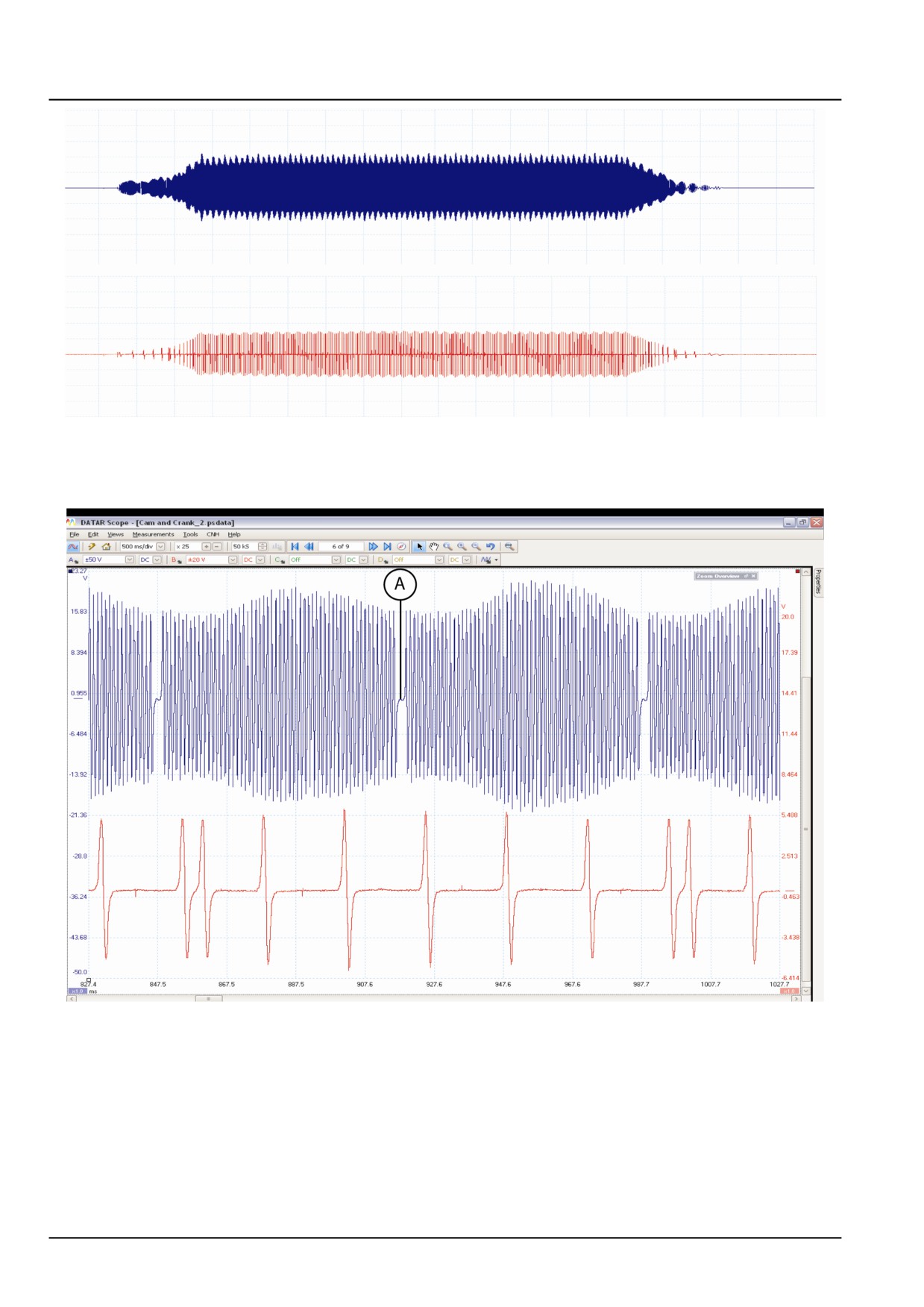
Figure 6 shows the ideal full signal of the crank and
cam position from the point of when the engine is
turned on , and until it is turned off.
BAIL11CVT087FMA
7
(A) = Sync Trigger
6.
Figure 7 shows the expected clean signal captured
by the DATAR scope, each sync trigger in Channel A
(Blue) is one crank rotation and each double fluctua-
tion in the channel B (red), is one cam rotation . With
two full crank rotations there is one full cam rotation.
The amplitude will increase with the engine speed.
This means the voltage can increase from ± 20 - 30
V
47524331 18/04/2013
10.1 [10.001] / 6
Engine - Engine and crankcase
Engine - Disconnect
Prior operation:
Remove the battery, for further information refer to Battery - Remove (55.302)
Prior operation:
Drain the engine coolant, for further information refer to Engine cooling system - Drain fluid (10.400)
Prior operation:
Discharge the air conditioning system, for further information refer to Air conditioning - Discharging (50.200)
Prior operation:
Remove the selective catalytic reduction (SCR) exhaust line, for further information refer to Exhaust pipes - Remove
(10.254)
Prior operation:
Remove the front AoH converter, for further information refer to Air-over-Hydraulic (AoH) converter - Remove
(33.350)
Prior operation:
Remove the front wheels, for further information refer to Front wheels - Remove (44.511)
WARNING
Heavy objects!
Lift and handle all heavy components using lift-
ing equipment with adequate capacity. Always
support units or parts with suitable slings or
hooks. Make sure the work area is clear of all
bystanders.
Failure to comply could result in death or seri-
ous injury.
W0398A
WARNING
Avoid injury!
Handle all parts carefully. Do not place your
hands or fingers between parts. Use Personal
Protective Equipment (PPE) as indicated in this
manual, including protective goggles, gloves,
and safety footwear.
Failure to comply could result in death or seri-
ous injury.
W0208A
1.
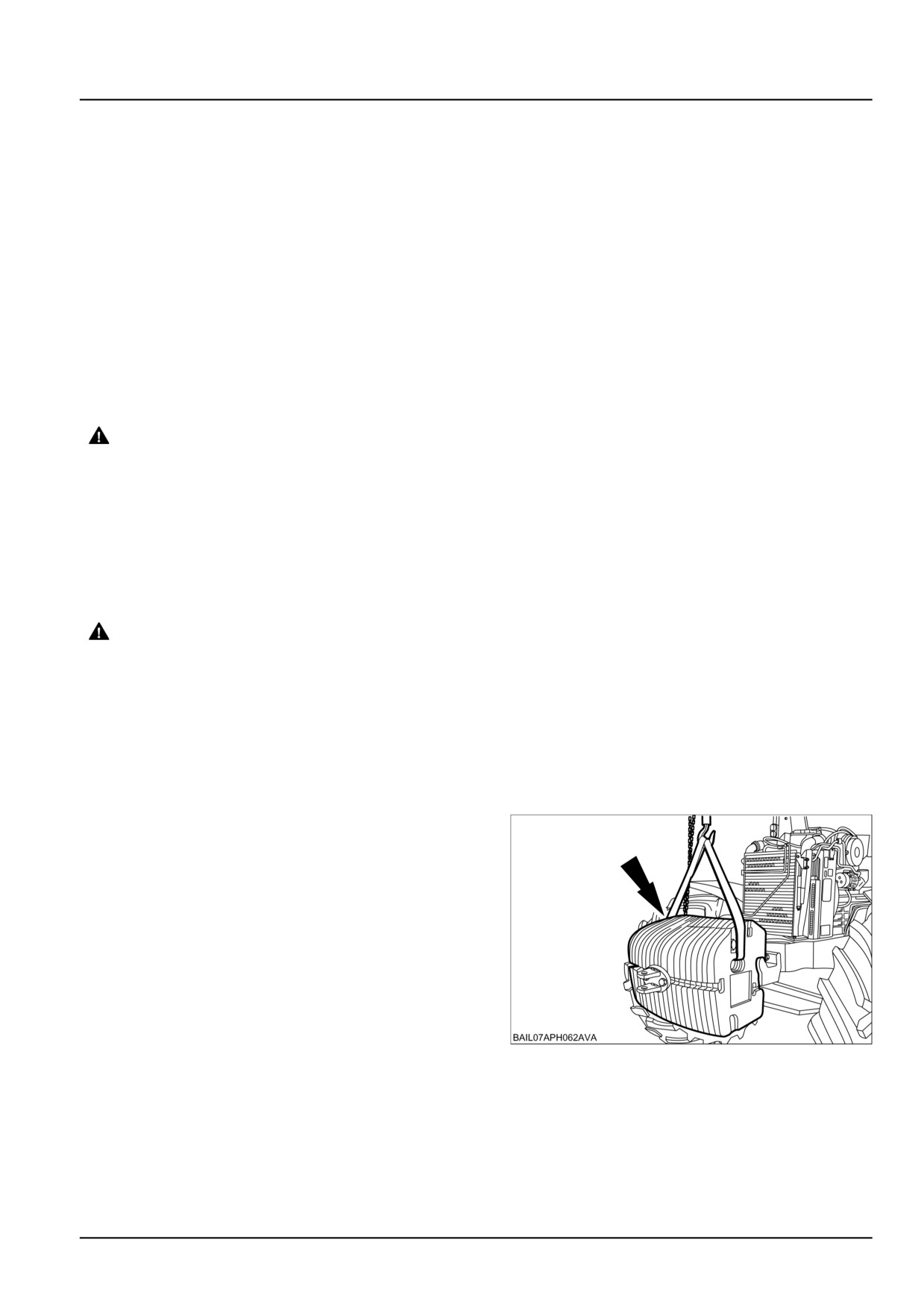
Using suitable lifting equipment support the front
weights.
BAIL07APH062AVA
1
47524331 18/04/2013
10.1 [10.001] / 7
Engine - Engine and crankcase
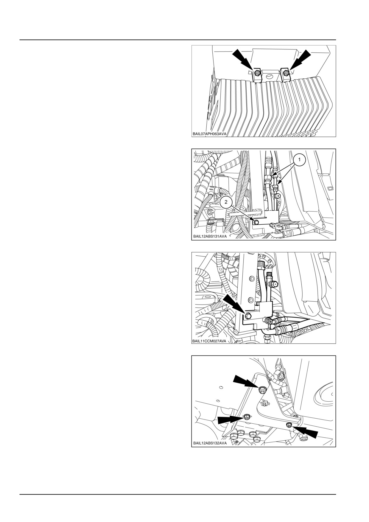
2.
Disconnect and remove the front weights from the
weight carrier.
BAIL07APH063AVA
2
3.
Disconnect the air conditioning hoses (1) and detach
the bracket (2).
NOTE: Cap all open connections to prevent contamination
of the system.
BAIL12ABS131AVA
3
4.
Detach the air conditioning pipe bracket from the en-
gine frame.
BAIL11CCM027AVA
4
5.
Remove the front AoH bracket lower bolts.
BAIL12ABS132AVA
5
47524331 18/04/2013
10.1 [10.001] / 8
Engine - Engine and crankcase
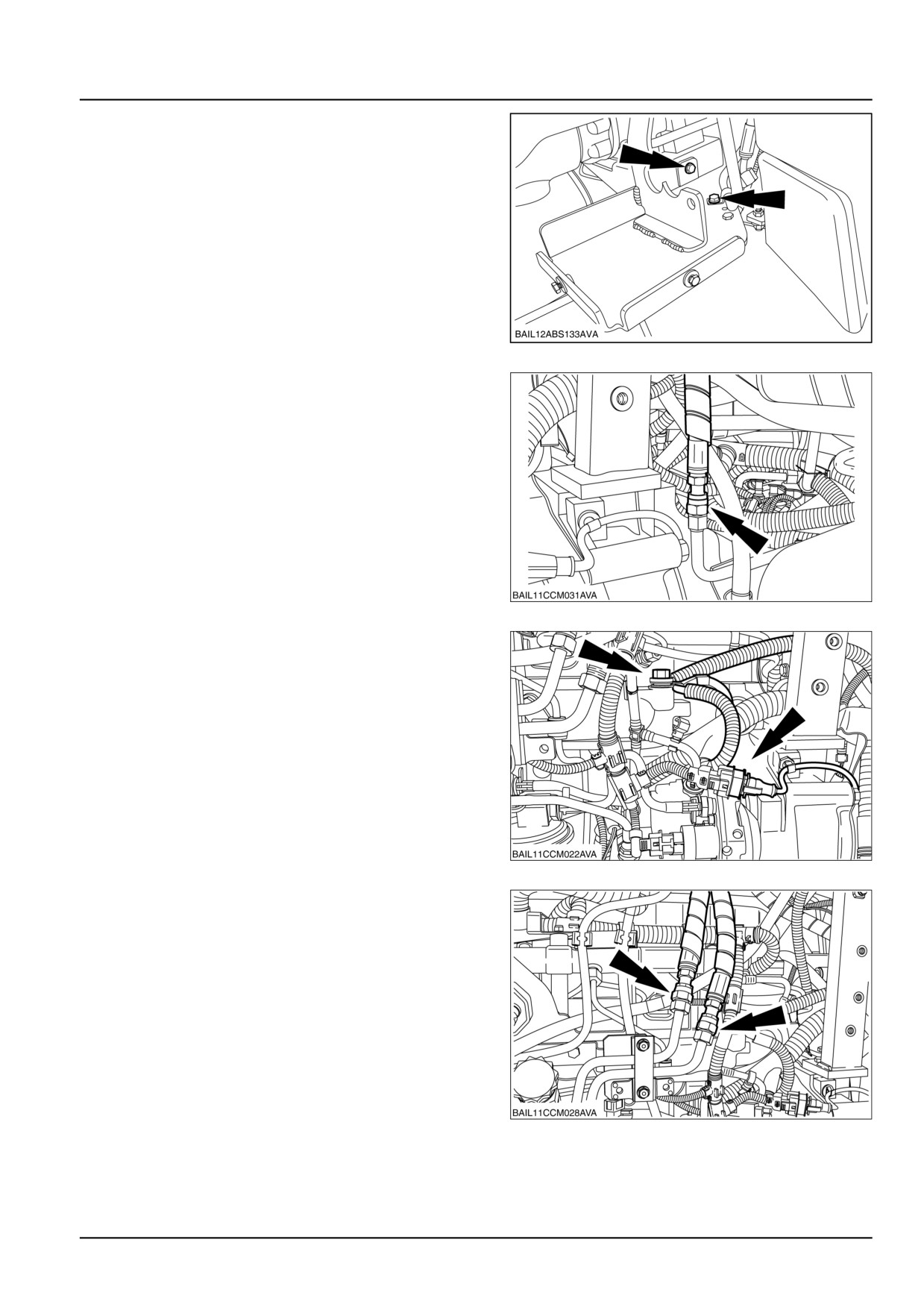
6.
Detach the pipe bracket and remove the AoH
bracket.
BAIL12ABS133AVA
6
7.
Disconnect the brake valve supply hose (if fitted).
BAIL11CCM031AVA
7
8.
Disconnect the flywheel position sensor electrical
connector.
BAIL11CCM022AVA
8
9.
Disconnect the steering hoses.
NOTE: Make a note of the position of the hoses to aid in-
stallation.
BAIL11CCM028AVA
9
47524331 18/04/2013
10.1 [10.001] / 9

Engine - Engine and crankcase
10. Disconnect the fuel supply and return lines.
BAIL11CCM283AVA
10
11.
Disconnect the diff lock and suspension pipes.
BAIL12ABS134AVA
11
12. Disconnect the trailer brake air supply pipe.
BAIL08CVT135AVA
12
13. Disconnect the heater supply hose from the rear of
the engine cylinder head.
BAIL12ABS135AVA
13
47524331 18/04/2013
10.1 [10.001] / 10
Engine - Engine and crankcase
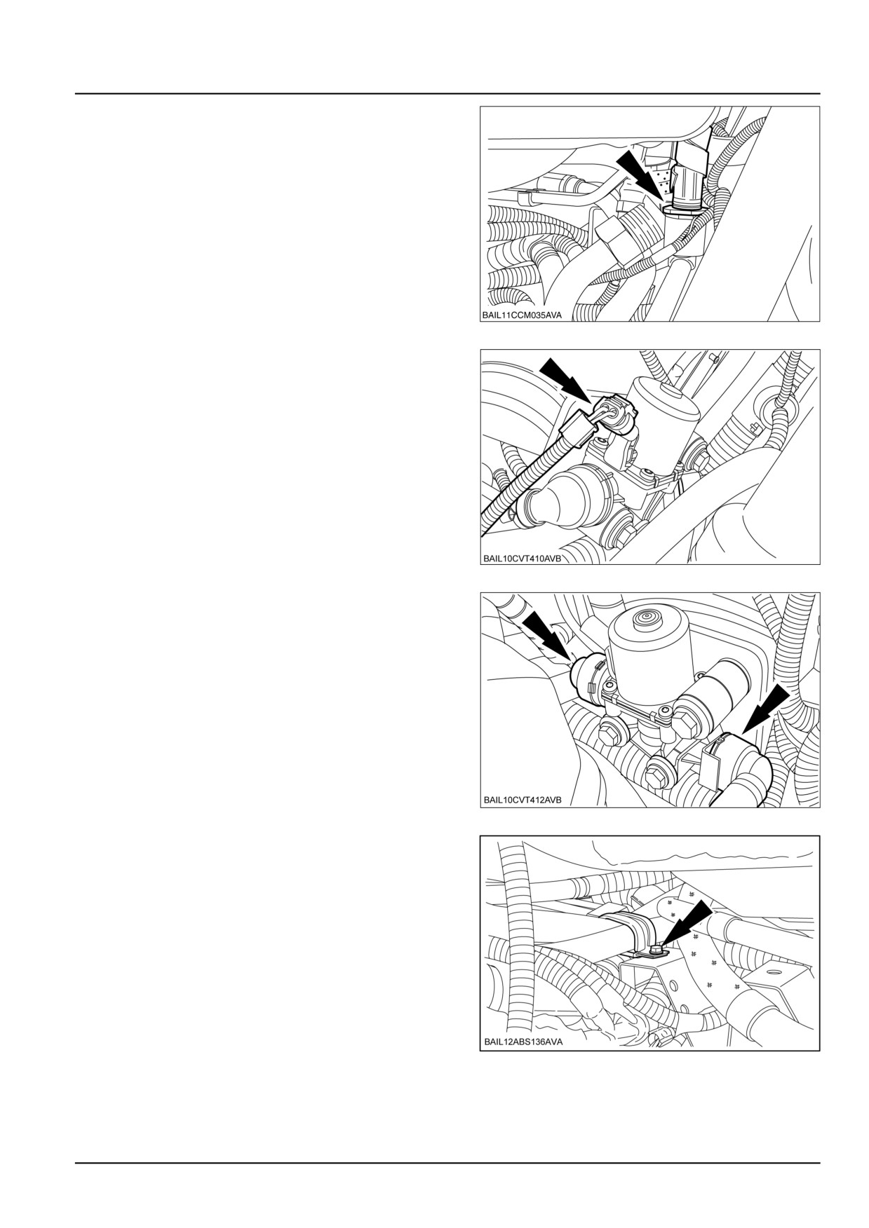
14. Disconnect the steering hydraulic oil supply pipe.
BAIL11CCM035AVA
14
15. Disconnect the SCR coolant control valve electrical
connector.
BAIL10CVT410AVB
15
16. Disconnect the coolant line connectors from the SCR
coolant control valve.
BAIL10CVT412AVB
16
17. Detach the cab heater hose retaining bracket.
BAIL12ABS136AVA
17
47524331 18/04/2013
10.1 [10.001] / 11
Engine - Engine and crankcase
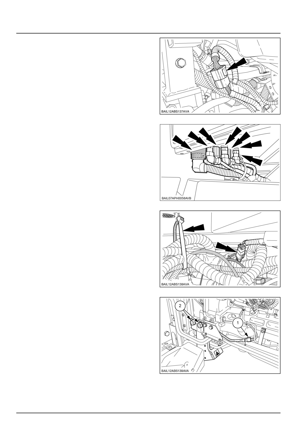
18. Disconnect the engine harness electrical connector.
BAIL12ABS137AVA
18
19. Disconnect the cab electrical connectors.
BAIL07APH058AVB
19
20. Disconnect the electrical connector and cut the cable
tie.
BAIL12ABS138AVA
20
21. Disconnect the radar electrical connector (1) and re-
move the radar (2).
BAIL12ABS139AVA
21
47524331 18/04/2013
10.1 [10.001] / 12
Engine - Engine and crankcase
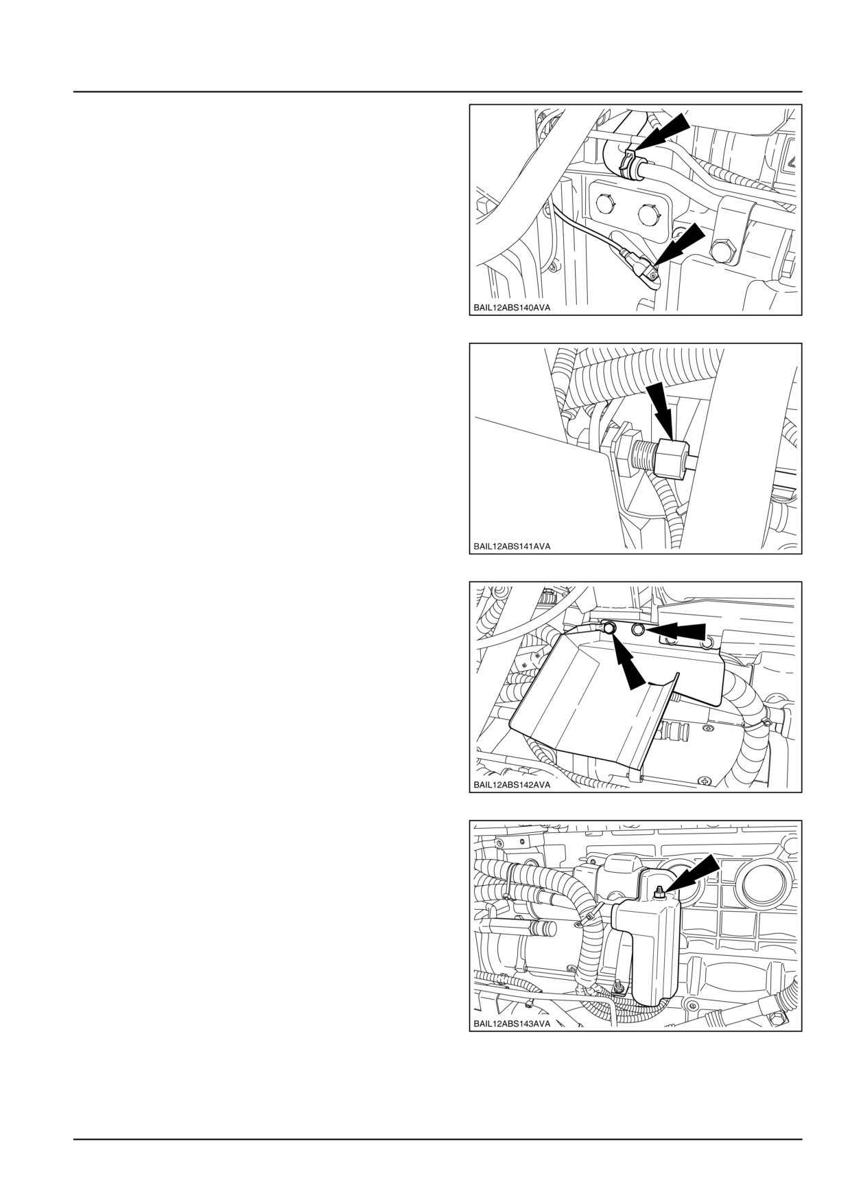
22. Remove the flywheel speed sensor and disconnect
the heater return hose.
BAIL12ABS140AVA
22
23. Disconnect the brake pipe.
BAIL12ABS141AVA
23
24. Remove the starter motor heat shield and earth.
BAIL12ABS142AVA
24
25. Remove the starter motor cover.
BAIL12ABS143AVA
25
47524331 18/04/2013
10.1 [10.001] / 13

This as a preview PDF file from best-manuals.com
Download full PDF manual at best-manuals.com
NEW HOLLAND T7
T7.170
I T7.185
I T7.200
I T7.210
I T7.220
I T7.235
I T7.250
I T7.260
I T7.270
2
3
YOUR NEEDS VARY CONSTANTLY. T7
ADAPTS CONTINUOUSLY.
MORE PRODUCTIVITY AND POWER
T7 tractors boast New Holland's cutting-edge ECOBlue™ SCR technology for Tier 4A compliance.
This means that the 6.7 litre Nef engine benefits from exceptional breathability for a significant
performance advantage. T7 tractors now offer up to 19hp more power and 139Nm of torque over
the existing T7000 range. With Engine Power Management, up to 51hp extra is available for
optimum productivity.
ABSOLUTE DRIVING PLEASURE
T7 tractors are designed to make operation even easier. The new SideWinder™ II armrest ensures
the tractor is less tiring to use over extended periods. The Horizon™ cab offers exceptionally low
noise levels of just 69dB(A) and brilliant all-round visibility.
LOWER OPERATING COSTS
T7 tractors benefit from Nef engines that use ECOBlue™ SCR emission reduction
technology. Matched with the advanced Auto Command™ transmission, fuel use
is cut by up to 10%. 600 hour engine service intervals continue to set the standard.
MAXIMUM VERSATILITY
The nine-model T7 series has a power and transmission choice for every application.
Combined with their exceptional power to weight ratios of up to 25.8kg/hp(CV), these tractors
offer exceptional versatility. From draft to top work, spraying to transport, a T7 tractor will do it all.
EXACTLY WHAT IT SAYS ON THE BONNET
T7 tractors offer improved performance thanks to the Tier 4A ECOBlue™ SCR advantage, and these productivity
enhancing characteristics are immediately obvious to all users. How? Quite simply, it is on the bonnet. The first two
digits ‘T7’ refer to the tractor’s category and the following three, for example ‘270’, refer to the maximum Engine
Power Management horsepower. What does that mean to you? You can buy your T7 safe in the knowledge that it will
be able to cope with even the most demanding applications. New Holland for ultimate productivity peace of mind.
Engine speed
Max power with EPM [hp(CV)]
T7.170
171
EPM [hp(CV)]
T7.185
188
T7.200
203
T7.170
46
Rated power [hp(CV)]
T7.185
48
T7.210
212
T7.220
218
T7.170
125
T7.200
48
T7.210
47
T7.235
234
T7.185
140
T7.250
250
T7.200
155
T7.220
51
T7.235
49
T7.260
260
T7.210
165
T7.270
269
T7.220
167
T7.250
50
T7.260
45
T7.235
185
T7.270
41
T7.250
200
T7.260
215
EPM according to the load on transmission, PTO and hydraulics.
T7.270
228
4
5
THE RANGE
A LARGER FAMILY FOR DEMANDING
PROFESSIONALS.
New Holland T7 tractors can be specified to match your specific business needs.
Spanning rated powers from 125hp to 228hp, the nine model T7 range can be fitted with a choice of
semi-powershift, full-powershift or constantly variable transmission (CVT). All models can be fitted with a
New Holland loader, all tractors have the option of a fully integrated front linkage and PTO.
AN ARMREST TO SUIT YOU
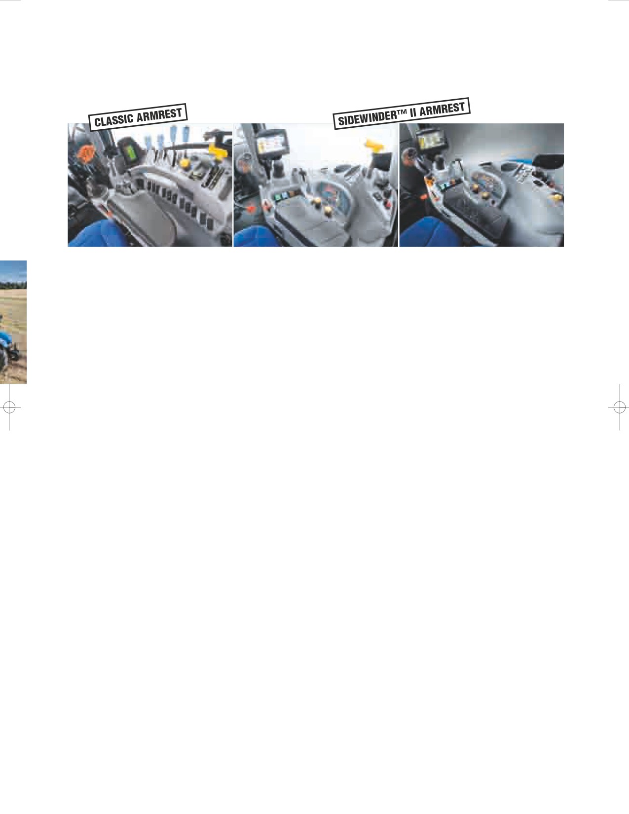
Range Command™ and Power Command™ tractors’ can be specified either with a classic
armrest or New Holland’s advanced SideWinder™ II armrest, complete with
CommandGrip™ handle and IntelliView™ III monitor, as an option. SideWinder II is standard
on Auto Command™ tractors and benefits from the advanced force based CommandGrip
for speed and direction control.
6
7
OPERATOR ENVIRONMENT
HORIZON™ CAB MORE SPACE, BETTER VISIBILITY.
DESIGNED FOR COMFORT AND PRODUCTIVITY
Step up into a standard T7 Horizon™ cab, and regardless
of its specification, you will find it has been designed to fit
you perfectly. Note how the seat and steering wheel adjust
to suit you. All-round visibility is about as good as it gets.
Noise levels are exceptionally low, helping to reduce fatigue.
Enjoy how the seat, cab and axle suspension cushion the
ride. From air-conditioning to optional full climate control,
the Horizon cab will do its best to keep you comfortable.
FROM DUSK TO DAWN
Cab roof, engine hood and fender
worklights are easily controlled
from a dedicated switch panel.
The operator can set the lights to
match a broad range of applications
for safer, more productive operation.
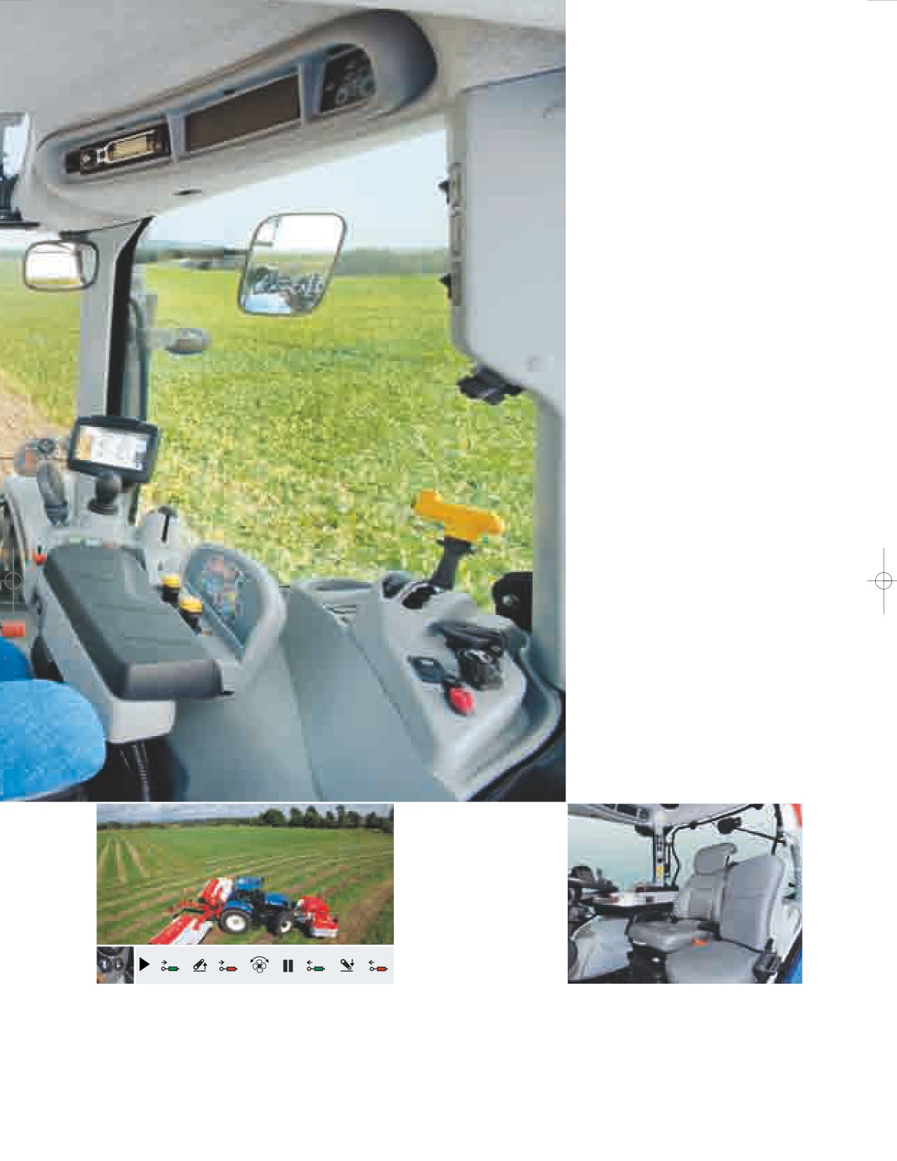
EASY CAB ACCESS
Manufactured from a single piece
of glass, the one-piece doors on
New Holland T7 tractors open
wide to provide easy cab access.
The doors are easy to open from
inside the cab and, equally
important, can be closed from the
operator’s seat. Small details that
make a big difference.
AUTO COMFORT™ SEAT
For operators who spend extended
hours in the tractor, the enhanced
comfort provided by the heated
Auto Comfort™ seat is worth
considering. Fitted with a large air
reservoir to further reduce whole
body vibration, the Auto Comfort
seat delivers an even smoother ride.
8 sec
5 sec
8 sec
5 sec
HEADLAND TURN SEQUENCING
Automated features are only of use when the operator feels comfortable setting
them up and using them. New Holland Headland Turn Sequencing has been refined
and developed over several years to match ease of operation with in-field efficiency.
The system allows the operator to record and store the sequence of operations at
the headland. These are then ‘played back’ automatically when HTS is activated.
Simple and a great way to reduce fatigue over extended working periods.
8
S
9
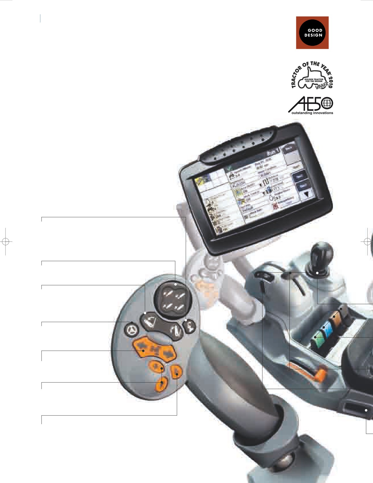
IDEWINDER™ II ARMREST & COMMANDGRIP™ HANDLE
SIDEWINDER II.
As awarded by The Chicago Athenaeum:
Museum of Architecture and Design.
DESIGNED BY FARMERS, FOR FARMERS
As modern tractors offer increasingly sophisticated features there is a risk that they
become more difficult to understand and operate. At New Holland we have made
everything simpler with the SideWinder™ II armrest, designed by farmers, for farmers.
All key controls are accessed from the armrest. Throttle, transmission and hydraulics.
Everything you need to control is quickly and easily accessible. More advanced
features can be quickly accessed. It does not take long to master a T7 tractor.
INTELLIVIEW™ III TOUCHSCREEN.
All the information you need at a
glance. Fingertip adjustment of all key
settings and compatible with the New
Holland IntelliSteer™ guidance system.
• Headland turn sequencing, HTS.
Press to record, store and activate
automated headland turn.
• Finger tip control for
up to two remote valves.
• Rear linkage raise / lower.
• Optional IntelliSteer™
autoguidance, automated
steering engagement.
• Forward reverse
shuttle switch.
• Change transmission ratio
up and down.
• Engage Auto Field
or Auto Transport mode.
"SideWinder II and CommandGrip make
operating a T7 tractor so simple. Of equal
importance, I can show an operator new to the
tractor how everything operates quickly and
easily. SideWinder II is a real advance in tractor
design and a genuine aid in daily productivity."
EASY ACCESS TO ADVANCED FEATURES
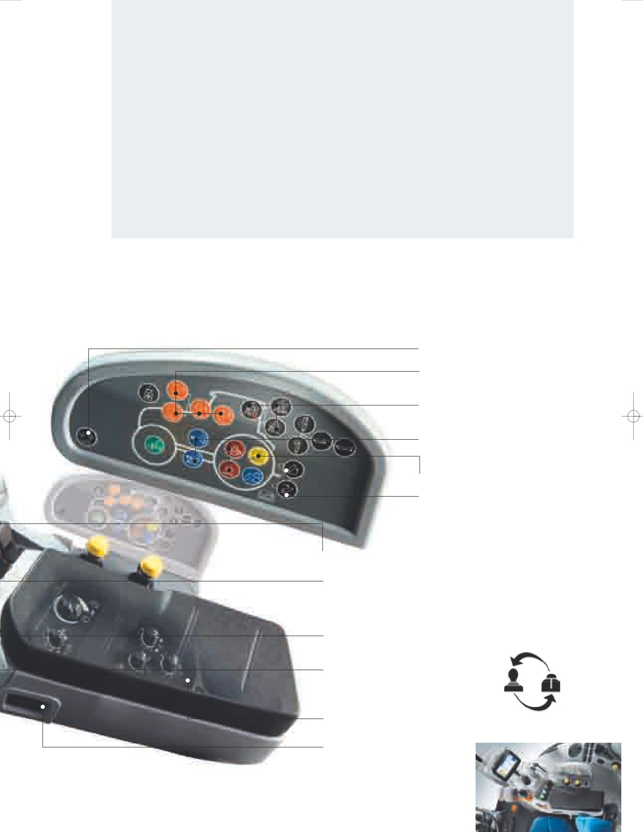
Push the symbol. Activate the feature. The Integrated Control Panel, ICP,
makes it simple to access advanced operating features. No need to
scroll through menus to set up Terralock traction management, HTS
headland turn sequencing, Auto PTO or ESM Engine Speed Managment.
• Select paddle or joystick control
for remote valves 3 and 4.
• Throttle up to your desired engine
speed, select Engine Speed
Management, and the speed is fixed.
• Press the Headland Turn Sequencing
button to record and replay the
functions you use most frequently.
• Engage Terralock and it will
automatically manage four-wheel
drive and differential lock selection.
• Auto PTO will disengage and reengage
the PTO during a headland turn.
• Three point hitch levelling and top link
extension at the touch of a button.
• Multifunction joystick. The joystick can be set
to operate the front linkage, loader or remote valves.
• Electronic remotes. Easy to reach paddles
provide fingertip hydraulic operation.
Flow and timing can be simply adjusted
through the IntelliView™ III touch screen.
• Rear linkage mouse. Lift heavy mounted
implements with absolute precision.
• Personalized positioning of the hydraulic
joystick and rear linkage mouse available
as a factory-fit option.
• Full access to further advanced
controls under the padded armrest.
• Electronic SideWinder™ II
adjustment. Move the armrest
to the position that suits you.
10
11
PLM
NEW HOLLAND GUIDANCE SYSTEMS
TO MATCH YOUR FARMING NEEDS
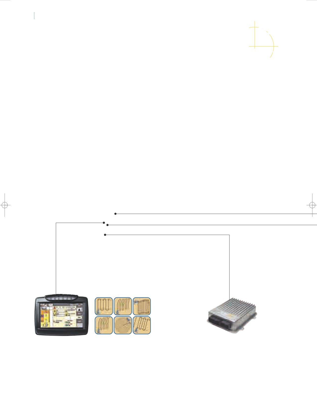
ALL WIRED UP READY FOR YOUR CHOSEN GUIDANCE SYSTEM
Series T7 tractors can be specified with a fully integrated New Holland designed and developed
IntelliSteer™ Automatic Steering System. Matching DGPS or RTK Technology to fully integrated
control, IntelliSteer helps ensure parallel pass to pass accuracy of up to 1 - 2cm*. IntelliSteer
is ideal for precision work in even the most demanding situations. It is designed to dramatically
improve operator performance and comfort. All this and more at the touch of a button.
* Using RTK correction signal.
FULLY INTEGRATED INTELLISTEER™ GUIDANCE
Guidance system choice will relate to the intended applications and the need to
integrate with existing systems. With T7 series tractors, all IntelliSteer options operate
via factory installed systems that facilitate installation and upgrades. This enables the
selected package to be modified and upgraded simply and more economically.
INTELLIVIEW - VISIBLE INTELLIGENCE
INTEGRATED CONTROL SYSTEMS
The IntelliView™ Plus II and IntelliView™ III monitors can be used to set
The New Holland IntelliSteer™ System uses
up the optional New Holland auto guidance systems, and includes a
built in T3 terrain compensated correction
visual interface that can be employed when operating the IntelliSteer™
signals (roll, pitch, yaw) to keep the Navigation
system. The IntelliView™ III monitor has a touchscreen display which
Controller II informed of the tractor's
allows the programming of a variety of guidance paths, from straight
orientation. Also integrated into the hydraulic
A-B runs to the most complex adaptive curves. You can also
system is a control valve which converts the
personalize your settings simply and easily and even transfer
signals from the Navigation Controller II into
information from your tractor, direct to your Precision Farming software.
hydraulic movements of the steering system.
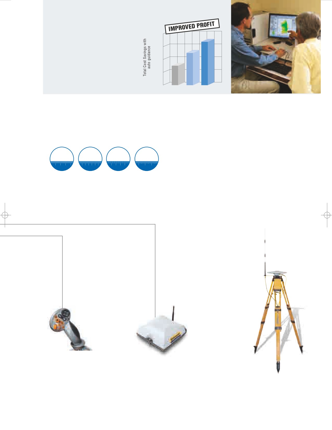
GOOD GUIDANCE SAVES MONEY
IntelliSteer helps improve overall
operating efficiency. In poor light
or during long working days,
precision driving is not compromised.
Improved efficiency saves money.
It is as simple as that.
0
AUTONOMOUS HP/XP RTK
LEVELS OF ACCURACY AND REPEATABILITY
New Holland offer four levels of accuracy. This enables you to select the right
IntelliSteer™ system to match your needs and budget. When using RTK correction
with IntelliSteer you can enjoy guaranteed year on year repeatability.
Autonomous
OmniSTAR® XP
OmniSTAR® HP
RTK GPS
30 cm
7 cm
5 cm
2.5 cm
15
20
25
30
5
6
7
8
9
10
3
4
5
6
0
1
2
INTELLISTEER.
NH 262 RECEIVER
RTK BASE STATION
ON AND OFF SIMPLICITY
The NH 262 receiver is capable of
An RTK base station can
The CommandGrip™ handle
working with Autonomous,
be used to broadcasts a
incorporates a single button that is
OmniSTAR or RTK correction. For
correction signal to
used to activate the IntelliSteer system.
RTK applications a slim profile
achieve a pass to pass
New Holland makes advanced
radio mounts underneath the
accuracy of 1-2cm.
technology accessible.
receiver.
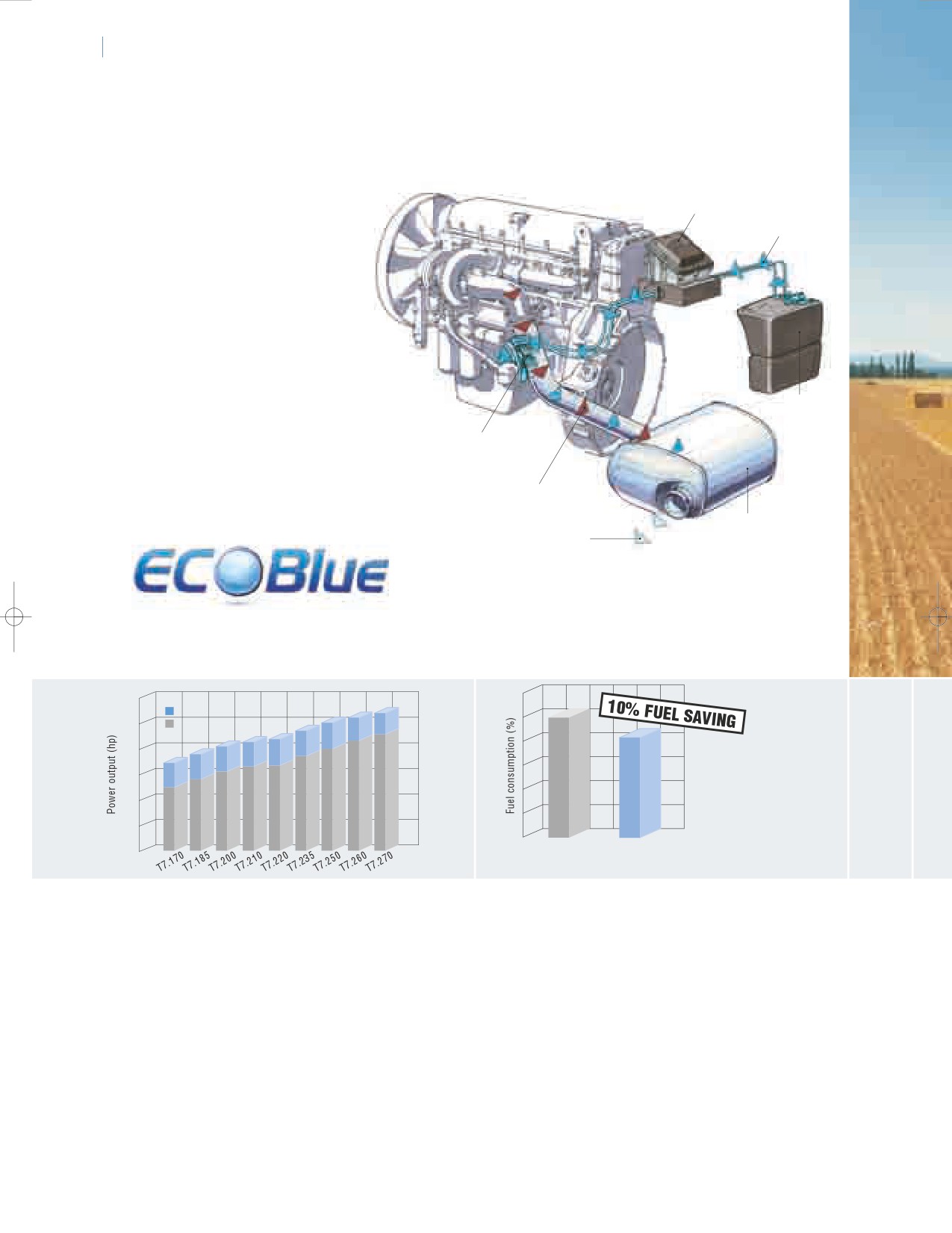
12
13
ENGINE
ULTIMATE ENGINE BREATHABILITY
T7 tractors are powered by the very
latest generation of Nef engines.
Supply module
Now with proven ECOBlue™ SCR
AdBlue/DEF additive
technology, to meet the stringent
Tier 4A emissions standards. This
uses AdBlue® to transform the
harmful nitrogen oxides contained
in the exhaust gas into harmless
water and nitrogen. This
aftertreament system is separate
from the main engine which means
only clean, fresh air is fed into the
engine. What does this mean?
AdBlue/DEF tank
Clean running power units with
improved performance and
Dosing Module
enhanced fuel efficiency.
Exhaust gas containing NOx
SCR Catalyst
Nitrogen and Water
300
EPM
250
Rated power
200
150
100
50
T7000
T7
0
Tier 3
Tier 4A
ECOBLUE™ SCR:YOUR POWER GUARANTEE
EXCEPTIONAL FUEL ECONOMY:
ECOBlue™ SCR guarantees exceptional
The existing Tier 3 Nef engine series has
performance and high productivity, independent of
established itself as the benchmark for
fuel quality, sulphur levels and without the need for
fuel economy. The new Tier 4A Nef power
costly diesel additives. With rated powers that span
units in T7 tractors go one stage further,
125hp to 228hp, all T7 models generate extra power
with fuel use cut by up to 10% when
of between 171hp to 269hp with EPM.
compared to existing T7000 models.
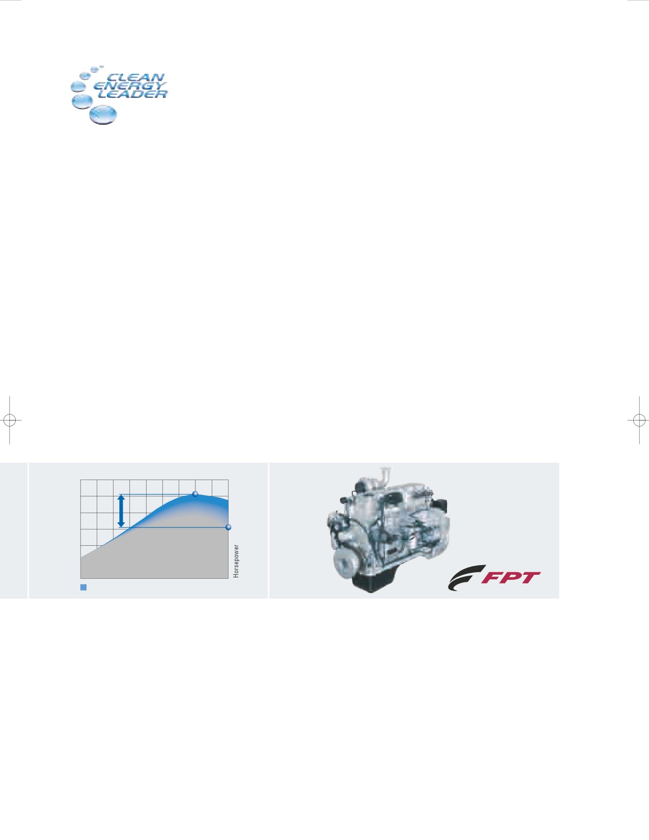
ENGINE SPEED MANAGEMENT
In applications where a constant PTO speed
is required, the operator can select Engine
Speed Management. This will ensure this
selected speed is accurately maintained
under changing loads. In many applications,
this will enable a fixed forward speed to be
maintained in difficult terrain.
Engine speed
51hp
EPM according to the load on the
POWERTRAIN TECHNOLOGIES
transmission, PTO and hydraulics.
ENGINE POWER MANAGEMENT
POWERED BY FPT INDUSTRIAL
Engine Power Management is an renowned
New Holland are not going it alone when it comes to Tier 4A technology,
New Holland tractor feature. In short, the
they can draw on the experience of their engine development partner:
engine develops more power and torque
FPT Industrial.
according to the load on the transmission,
hydraulics and PTO. On a T7.220 tractor,
Pioneers: Fiat invented Common Rail technology in the 1980s and
EPM will deliver up to 51hp extra, but only
brought it to the masses in 1997 on the Alfa Romeo 156. They were
when it is needed, to maintain performance.
the very first to introduce it on agricultural machines. Pioneering. Always.
Cleaner: Fiat S.p.A. have the lowest overall CO2 emissions of any
automotive manufacturer in Europe. Cleaner. Everywhere.
Proven: FPT Industrial have already produced over 150,000 SCR
engines during the last five years for the haulage industry. Reliability.
Confirmed.
After all, only those who invented it can reinvent it.
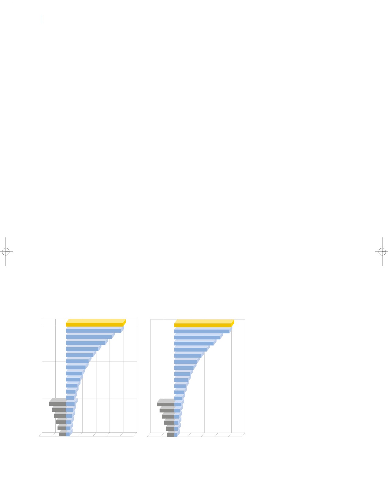
14
15
RANGE COMMAND™ AND POWER COMMAND™ TRANSMISSION
PUSH BUTTON SIMPLICITY.
YEARS OF PROVEN TECHNOLOGY
Range Command is a simple, rugged and well proven transmission.
It provides clutch-free gear changes within each working range.
It is the ideal choice for general farm applications. Power Command
is a full-powershift transmission: you select the gear speed
you want by simply pushing up or downshift buttons.
Only New Holland offers such a simple transmission choice.
Range Command™ Transmission*
Power Command™ transmission*
Reverse Forward
Reverse Forward
SEMI-POWERSHIFT UP TO T7.210.
19
(1725rpm)
42
19
(1725rpm)
42
18
40,7
18
40,7
FULL POWERSHIFT
17
33,8
17
33,8
FROM T7.170 TO T7.260
16
28,8
C
16
28,8
Range Command and Power
15
23,9
15
23,9
Command are based around the
14
19,9
14
19,9
same gear offering. You can choose
13
16,6
13
16,6
between a standard 40kph 18x6
12
14,3
12
14,1
or 28x12 creep speed transmission
11
11,9
11
11,7
10
10,2
B
10
10
or opt for an extra high ratio 19x6
9
8,4
9
8,3
or 29x6 'direct drive' alternative.
8
7
8
6,9
This can deliver either 40kph at a
7
5,8
7
5,7
reduced engine speed for economy
12,4
6
6,2
12,9
6
4,9
or a high 50kph transport speed.
10,3
5
5,1
10,8
5
4
8,8
4
4,4
A
9,2
4
3,4
7,3
3
3,6
7,6
3
2,9
6,1
2
3
6,3
2
2,4
5,1
1
2,5
5,3
1
2,0
20
10
0
10
20
30
40
50
20
10
0
10
20
30
40
50
kph
kph
*T7.200 19x6 40kph ECO model shown with 650/65R42 tyres fitted
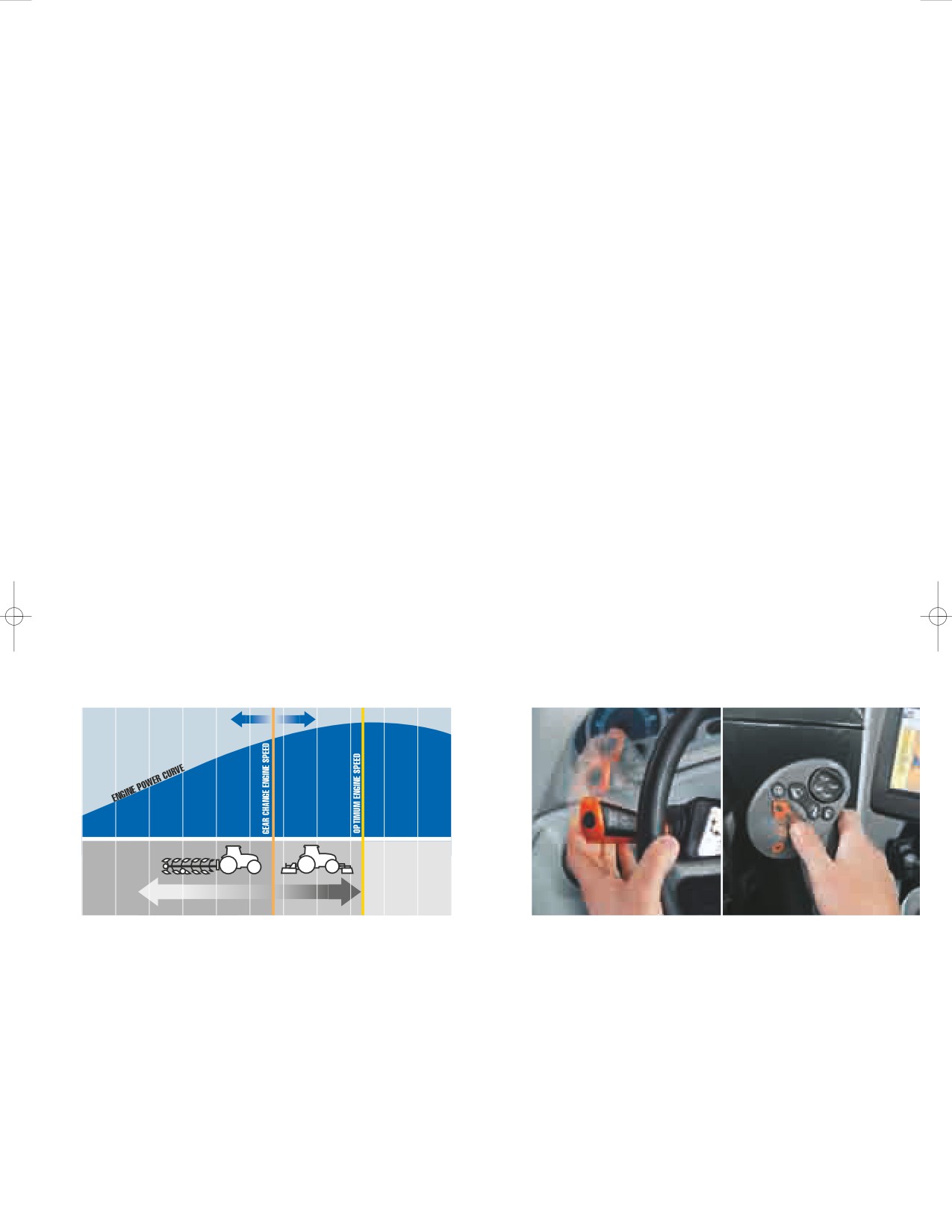
A SMOOTHER SHIFT IN FIELD AND TRANSPORT
IntelliShift™ gear change management ensures T7
tractors deliver a seamless powershift between each
and every ratio. Programmed to scrutinise transmission
load, speed and transmission oil temperature,
IntelliShift delivers smooth changes all day long.
AUTOMATED
SHIFT POINT
HIGH TOLERANCE
LOW TOLERANCE
WORK TOGETHER:
EASY SHUTTLE
AUTOMATION, COMFORT AND PRODUCTIVITY
The clutchless forward reverse shuttle, operated via
Easy to set up and brilliantly effective, Auto Transport and Auto
the steering column or the CommandGrip™ handle
Field modes can really reduce the effort required to work a T7
fitted to the optional SideWinder™ II armrest, can be
tractor over a long working day. With Auto Transport, the tractor
programmed to automatically manage transmission
will seamlessly shift ratios like an automatic car.
shifts during a direction change. As a further option,
It will even sense if the tractor is being pushed by a loaded
an electronic park brake can be specified. This is
trailer while descending a hill. If it does, it holds the current
operated via the shuttle lever, securing the tractor
gear to provide engine braking. Auto Field manages both the
when neutral is selected.
engine speed and transmission to optimise performance and
economy. In PTO applications, where a constant engine speed
is the priority, the system will select the transmission ratio to
match the load on the engine. In draft applications, Auto Field
will allow the engine speed to drop to fully exploit the available
torque rise before selecting a lower ratio under load.
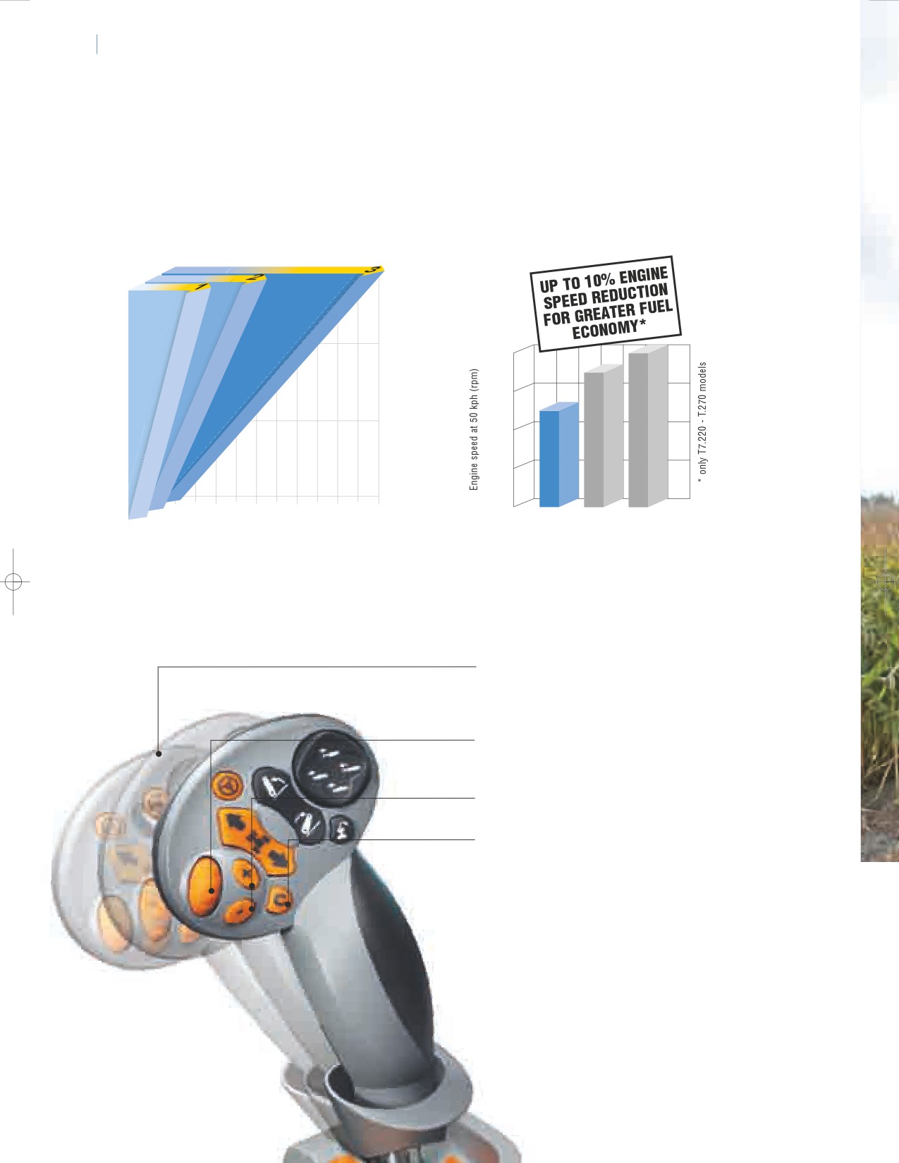
16
A
17
UTO COMMAND™ TRANSMISSION
INNOVATIVE AUTO COMMAND™ TRANSMISSION
OFFERS ADVANCED NEW HOLLAND FEATURES
Designed and built by New Holland, the T7 Auto Command is available from the T7.170 to the T7.270.
This new generation of CVT transmissions benefits from multi direct drive points offering 100% mechanical
efficiency, plus advanced double clutch control. It is the smoothest and most productive CVT available.
Speed diagram
1700
1700
1650
1600
1550
1500
1400
forward
1300
0
5 1015202530354045 50
New T7
Competitor A Competitor B
kph
A SPEED FOR EVERY NEED
MAKING THE MOST OF AVAILABLE TORQUE
Auto Command allows the operator to set a target
New Holland has developed its Auto Command™
speed of between 20m/hr right through to 50km/hr.
transmissions so they can exploit the low running
No steps. No range changes. Just seamless speed
speed, high torque New Holland engines. With 50kph
to match your every need.
ECO, the engine can run at a fuel efficient 1550 rpm.
• Force based movement enables the operator to change
speed and direction. On the ICP there is a switch to alter
the response of the speed change.
• Target speed adjustment - set a target speed to match
your exact needs. Perfect when moving between fields
or when crop yields have altered.
• Target speed selection - allows you
to change between three target speeds
• 4 DRIVING MODES TO SUIT YOUR DRIVING STYLE
- Auto Mode. Select the desired target
speed and Auto Command will match
the engine and transmission to maintain it.
- Cruise Mode. Once a desired operating
speed has been achieved, Cruise Mode
allows the operator to set the transmission to
maintain the speed for economy and productivity.
- Manual Mode. Allows the operator to set
the required engine and forward speed.
- PTO mode. As soon as the PTO is engaged,
Auto Command will operate to guarantee
a constant engine speed.
ABOUT AUTO COMMAND TRANSMISSION
"Auto Command makes operating at higher
transport speeds considerably safer. The hill
hold function is excellent, making it less stressful
when pulling onto a road from a steep side road
with a heavily laden trailer safer. Excellent fuel
savings too.”
ACTIVE STOPSTART
A key safety feature of Auto Command is Active StopStart.
When the tractor is brought to a standstill, the transmission
prevents the tractor moving backwards or forwards.
Even with a heavy load. When the transmission takes
up drive there is no risk of roll back on steep inclines.
For safe parking, an electronic brake is easily engaged
via the shuttle lever.
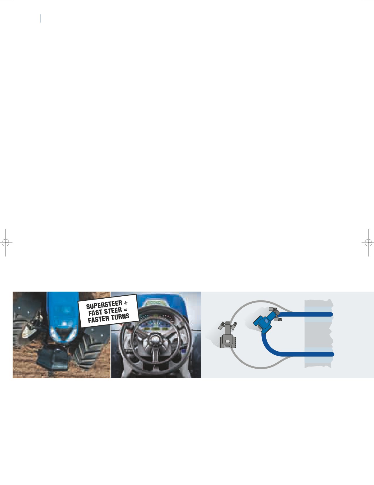
18
19
AXLES & TRACTION
FASTER TURNS. BETTER TRACTION.
GREATER PERFORMANCE
Axle strength and weight increase with engine power. This ensures a good power
to weight ratio is offered by all models, not just those with highest rated output.
T7.170 to T7.210 models have a gross vehicle weight of up to 11,000kg at 50kph,
this increases to 13,000 kg on the T7.220 and above.
More
Productivity
LESS TIME TURNING BOOSTS YOUR OUTPUT
New Holland leads the field in reducing the time it takes to turn on the headland.
Offering a tight 65 degree turn angle, the SuperSteer™ front axle option delivers
rowcrop agility, beating any tractor in the T7's category. The Fast Steer™ system,
compatible with all axle types, means full lock to lock turns are made even more
quickly and with minimal effort. You simply hold down the FastSteer steering rim
and the steering wheel is transformed into a proportional “joystick”.
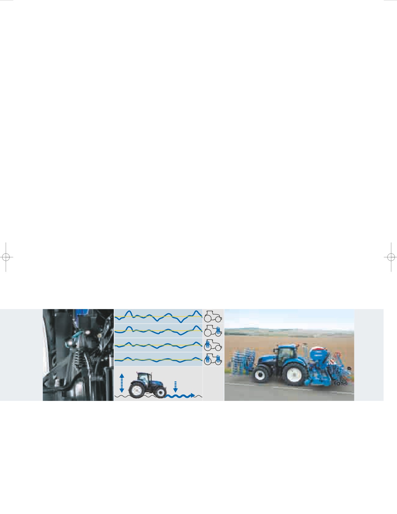
ADVANCED TRACTION MANAGEMENT
BRAKE OPTIONS
The New Holland Terralock™ system is well established.
All models are available with front axle brakes
The operator simply selects the traction package needed
and a choice of hydraulic or pneumatic trailer
for a specific application. Terralock will then manage drive
braking systems. On SideWinder™ II models,
to the front axle and engage and release the differential
an engine exhaust brake is optional. This can
locks automatically. During a headland turn or moving from
be used to help hold the tractor's speed on a
work to transport, Terralock will ensure the differentials and
gradual gradient.
four wheel drive are unlocked without operator intervention.
vibration at seat base
TERRAGLIDE™ FRONT AXLE AND COMFORT RIDE™ CAB SUSPENSION.
YOUR COMFORT PARTNERS.
Automatic two stage Comfort Ride™ cab suspension has established itself as a key advance
in operator comfort. Designed to complement the cushioned ride offered by the standard
air suspension seat, Comfort Ride helps reduce fatigue. Terraglide™ front axle suspension
is recommended in operations that include fast top work and extended transport duties.
Terraglide, with integral hub braking, is standard on tractors specified with a 50kph transmission.
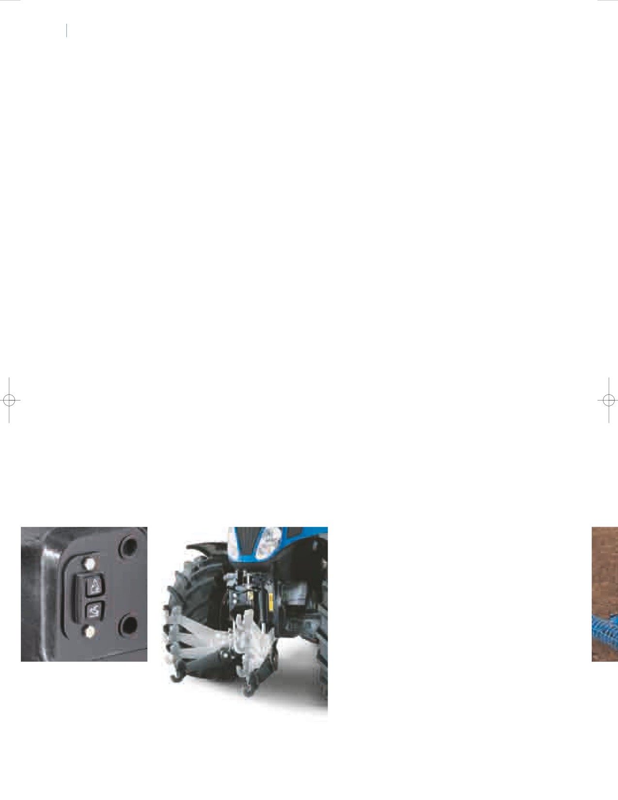
20
21
PTO AND FRONT / REAR LINKAGE
FEATURES TO BOOST YOUR PRODUCTIVITY
MAKING IT EASIER TO WORK
WITH FRONT MOUNTED IMPLEMENTS
New Holland T7 tractors are designed to
incorporate a fully integrated, factory fitted
front linkage and PTO. All controls are fully
integrated into the armrest and can be
programmed to operate with HTS. The linkage
arms fold up when not in use or can be used
to carry the full standard weight pack.
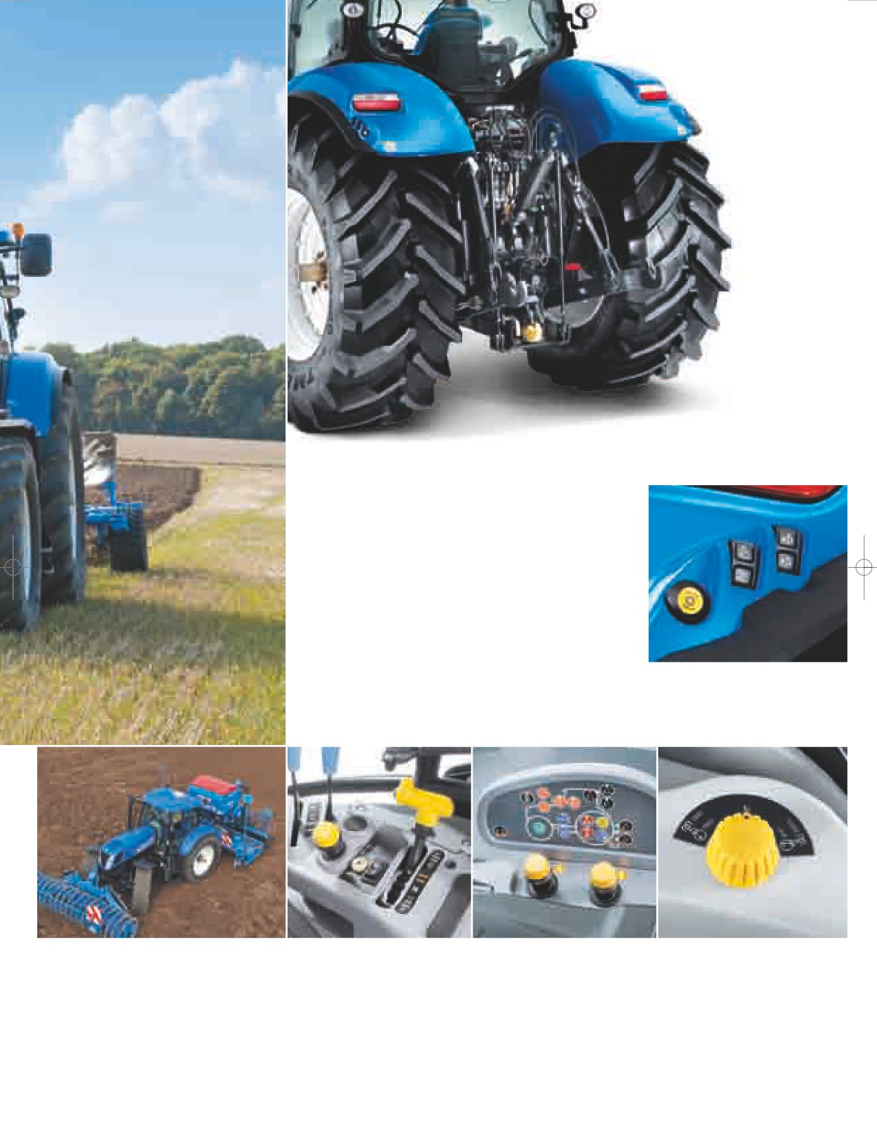
STRONG, EFFICIENT AND POWERFUL
The maximum lift capacity on T7.170 to T7.210
tractors is 8,275kg, climbing to a massive 10,463kg
on the T7.220 and above. The rear linkage and
hydraulics are designed to work with heavy mounted
equipment over extended periods. The system also
incorporates integral dynamic ride control shock
load protection. This will reduce bounce when
travelling with a heavy linkage load at transport
speeds. Fender mounted controls for the rear
linkage, a rear remote and the PTO are available.
AUTO PTO OPERATION
DIRECT DRIVE FOR FUEL EFFICIENCY
Auto PTO can be selected to
All T7 tractors are fitted with a direct drive PTO to minimise power loss
automatically disengage the PTO
between engine and implement. The PTO is engaged via a push-pull
as the rear linkage is raised above
control, with advanced Soft Start management. This modulates
a pre-set position. This protects the
engagement of high intertia attachments to protect the driveline.
PTO shaft and tractor. The system
Speed selection is via mechanical levers; SideWinder II T7.220 and
will also reengage drive as the
above feature electronic speed selection. Four speeds: 540, 540E,
linkage is lowered.
1000 and 1000E are available.
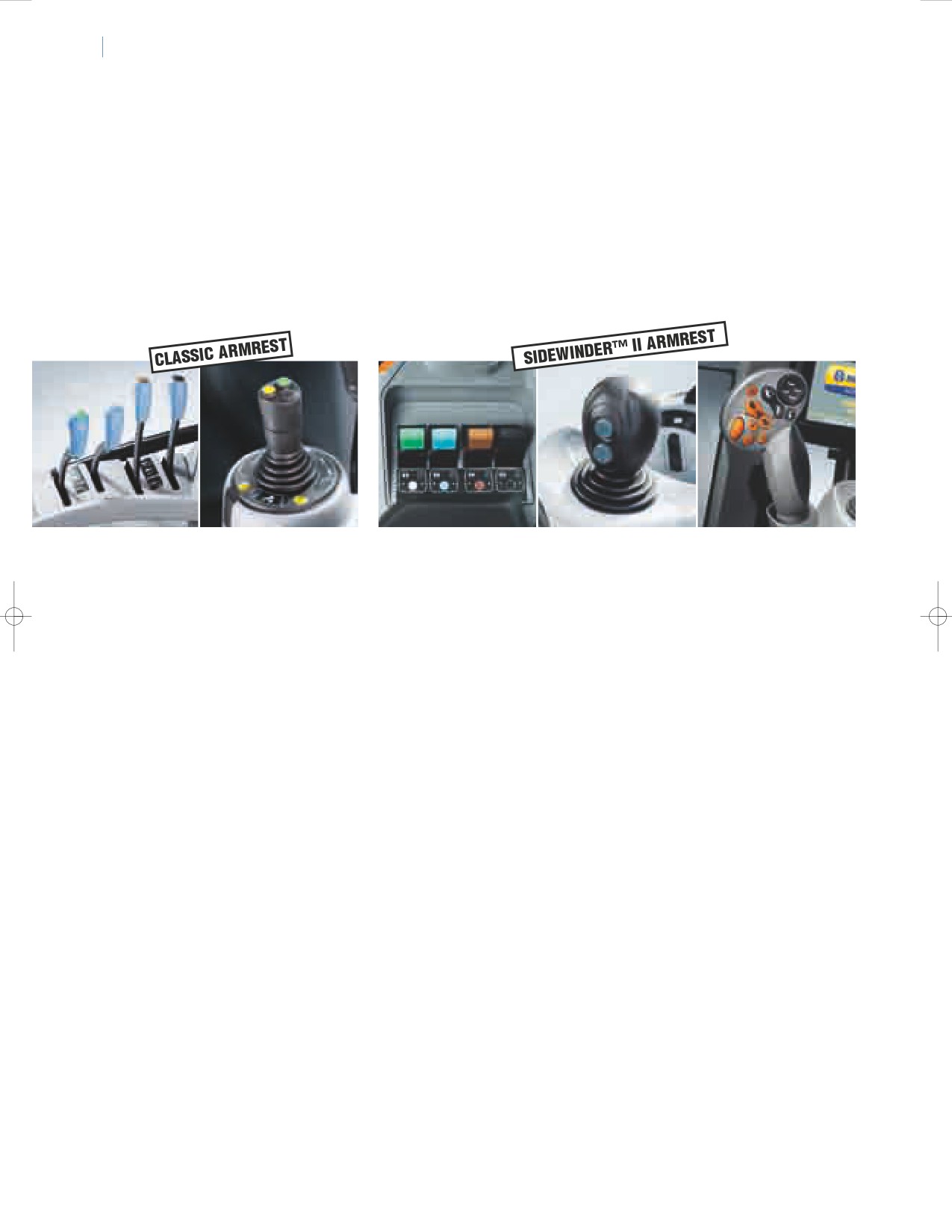
HYDRAULICS AND FRONT LOADERS
22
23
HYDRAULIC POWER TO MEET YOUR DEMANDS
CLOSED CENTRE LOAD SENSING HYDRAULICS
Hydraulic efficiency makes an important contribution to the overall performance of the tractor. T7.170
to T7.210 models are fitted with a 113 or 125 litres per minute hydraulic pump, this increases to 120
or 150 litres per minute on the T7.220 and above. T7 Auto Command models benefit from a priority valve
which guarantees optimum steering response in demanding hydraulic applications. For T7 Range Command
and Power Command models, a separate 65 litres per minute pump takes care of the steering. Full hydraulic
power is always available at the remote valves and lift linkage, but only as much as is needed. The variable
displacement pump only works on demand, which reduces fuel consumption.
ELECTRONIC OR MECHANICAL - YOU DECIDE
The Classic armrest incorporates mechanical controls for the remote valves.
SiderWinder™ II armrest models have electronic controls, with two controls on
the CommandGrip™ handle for ease of use. A hydraulic control joystick can be
specified. This can be set to operate front or rear valves.
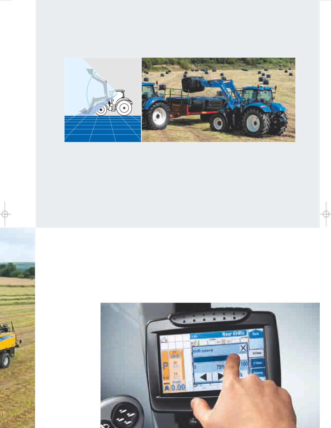
MAXIMUM
VISIBILITY
PURPOSE DESIGNED FOR PRODUCTIVITY
Purpose designed New Holland front loaders are available to fit T7.170 to T7.210 tractors.
From the operator’s seat, visibility remains excellent when the loader is both at ground level
and, thanks to the standard high visibility roof panel, when raised progressively to its full lift
height. This is an important design advantage of both the tractor and loader and a key to
ensuring the combination can deliver full productivity.
ADJUST THE FLOW ON UP TO NINE REMOTES
The electronic remote valves fitted on SideWinder™ II tractors each have individual
flow control. Hydraulic flow and timing to each valve can be individually adjusted
using simple ‘pop-up’ menus on the IntelliView™ III touch-screen.
All T7 models fitted with the classic armrest boast up to four deluxe mechanical rear
remote valves, whereas models equipped with the SideWinder™ II armrest benefit
from as many as five electro-hydraulic rear remotes. All models in the T7.170 to
T7.210 range offer three mid-mount valves, which is upped to four for the T7.220
to T7.270 models.
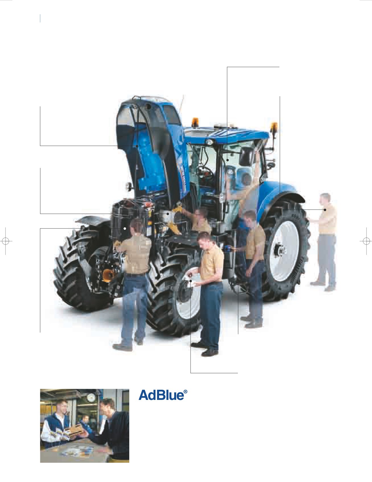
24
25
SERVICE AND BEYOND THE PRODUCT
360°: T7
The new T7 range has been designed to spend more time
• Top up the screen
working and less time in the yard. All service points are easy
wash bottle through
to access, and super long service intervals mean they will
the rear window.
spend more time in their natural environment: the field!
• Hydraulic oil levels
can be viewed via
• Single piece engine
sight glass at the
hood opens wide for
rear of the tractor.
full service access.
• The engine air filter is easy
to check, clean or replace,
with no need for tools.
• Cooling package opens
• The 48 litre AdBlue® tank's filler neck is
out to make cleaning
narrower than that of the standard fuel
faster and easier.
tank, which prevents inadvertent filling
with fuel. It only needs to be filled once
every two refills of the fuel tank.
• Engine oil check and fill points are
easy to reach, with no need to lift
the hood. This makes routine checks
faster and servicing simpler. You will
also still be able to enjoy the long
600 hour service intervals that you’ve
come to expect of New Holland.
WILL I BE ABLE
TO FIND ADBLUE® EASILY?
The answer is yes! It will be available on
your doorstep, through CNH Parts &
Service; just contact your local dealer for
more information. If that wasn’t enough,
AdBlue can even be delivered direct to
your farm for absolute convenience.
FINANCE TAILORED
TRAINED TO GIVE YOU
TO YOUR BUSINESS
THE BEST SUPPORT
CNH Capital, the financial services
Your dedicated New Holland dealer
company of New Holland, is well
technicians receive regular training
established and respected within the
updates. These are carried out both
agricultural sector. Advice and finance
through on-line courses as well as
packages tailored to your specific
intensive classroom sessions. This
needs are available. With CNH Capital,
advanced approach ensures your
you have the peace of mind that
dealer will always have the skills
comes from dealing with a financing
needed to look after the latest and
company that specialises in agriculture
most advanced New Holland products.
DEALER INSTALLED
ACCESSORIES
A comprehensive range of
approved accessories to
optimise machine performance
in all conditions can be supplied
and fitted by your dealer.
Want to make New Holland
a part of your everyday life?
Browse the comprehensive selection
A whole range of items are available
including hard wearing work clothing
and a vast selection of scale models,
together with so much more.
New Holland. As individual as you.
26
27
SPECIFICATIONS
MODELS
T7.170
T7.185
T7.200
T7.210
T7.220
T7.235
T7.250
T7.260
T7.270
Armrest type
New Holland engine*
Nef
Nef
Nef
Nef
Nef
Nef
Nef
Nef
Nef
No. of cylinders / Aspiration / Valves / Emission level
6/ T / 4 / Tier 4A
6/ T / 4 / Tier 4A
6/ T / 4 / Tier 4A
6/ T / 4 / Tier 4A
6/ T / 4 / Tier 4A
6/ T / 4 / Tier 4A
6/ T / 4 / Tier 4A
6/ T / 4 / Tier 4A
6/ WT / 4 / Tier 4A
ECOBlue™ SCR system (Selective Catalytic Reduction)
●
●●
●
●
●●
●●
●
●●
●●
Fuel system - High pressure Common Rail
●
●●
●
●
●●
●●
●●
●●
Approved biodiesel blend**
B20
B20
B20
B20
B20
B20
B20
B20
B20
Capacity (cm3)
6728
6728
6728
6728
6728
6728
6728
6728
6728
Bore and Stroke (mm)
104x132
104x132
104x132
104x132
104x132
104x132
104x132
104x132
104x132
Max. EPM horsepower - ISO TR14396- ECE R120 [kW / hp(CV)]
126 / 171
138 / 188
149 / 203
156 / 212
160 / 218
172 / 234
184 / 250
191 / 260
198 / 269
Max. horsepower - ISO TR14396- ECE R120 [kW / hp(CV)]
106 / 144
117 / 159
126 / 171
133 / 181
138 / 188
149 / 203
160 / 218
172 / 234
183 / 249
Rated EPM horsepower - ISO TR14396- ECE R120 [kW / hp(CV)]
118 / 160
129 / 175
140 / 190
147 / 200
151 / 205
162 / 220
173 / 235
181 / 246
192 / 261
Rated horsepower - ISO TR14396- ECE R120 [kW / hp(CV)]
92 / 125
103 / 140
114 / 155
121 / 165
123 / 167
136 / 185
147 / 200
158 / 215
168 / 228
Rated engine speed (rpm)
2200
2200
2200
2200
2200
2200
2200
2200
2200
Max. EPM torque - ISO TR14396 (Nm)
741@1500
810@1500
866@1500
912@1500
960@1500
1019@1500
1082@500
1120@1500
1160@1500
Max. torque ISO TR14396 (Nm)
612@1500
679@1500
740@1500
766@1500
825@1500
862@1500
927@1500
995@1500
1089@1500
Torque rise Standard / EPM (%)
53 / 45
52 / 45
49 / 42
45 / 43
54 / 47
46 / 45
45 / 44
45 / 43
50 / 39
Viscous coupled cooling fan
●
●●
●
●
●●
●●
●
●●
●●●
Reversible fan
O
O
O
O
O
O
O
O
O
Exhaust brake
O
O
O
O
O
O
O
O
O
Diesel tank capacity (Litres)
330
330
330
330
395
395
395
395
395
DEF/AdBlue® tank capacity (Litres)
48
48
48
48
48
48
48
48
48
Service interval (hours)
600
600
600
600
600
600
600
600
600
Range Command™ transmission (if equipped)
IntelliShift™ system
●
●●
●
●
-
-
-
-
-
Armrest type
● O
● O
●
O
●
O
-
-
-
-
-
Auto transmission functions
●
●●
●
●
-
-
-
-
-
Range Command™ Semi-Powershift (40 kph)
O
O
O
-
-
-
-
-
-
Number of gears / with Creeper (F x R)
18 x 6 / 28 x 12
18 x 6 / 28 x 12
18 x 6 / 28 x 12
-
-
-
-
-
-
Min. speed / Min. speed with Creeper (kph)
2.4 / 0.40
2.4 / 0.40
2.2 / 0.37
-
-
-
-
-
-
Range Command™ Semi-Powershift (40kph ECO or 50 kph)
O
O
O
O
-
-
-
-
-
Number of gears / with Creeper (F x R)
19 x 6 / 29 x 12
19 x 6 / 29 x 12
19 x 6 / 29 x 12
19x6 / 29x12***
-
-
-
-
-
Min. speed / Min. speed with Creeper (kph)
2.4 / 0.40
2.4 / 0.40
2.2 / 0.37
2.0 / 0.34
-
-
-
-
-
Power Command™ transmission (if equipped)
IntelliShift™ system
●
●●
●
●
-
-
-
-
-
Armrest type
● O
● O
●
O
● O
●
●●
●
●
-
Auto transmission functions
●
●●
●
●
-
Power Command™ Full-Powershift (40 kph)
O
O
O
O
O
O
O
O
-
Number of gears / with Creeper (F x R)
18 x 6 / 28 x 12
18 x 6 / 28 x 12
18 x 6 / 28 x 12
18 x 6 / 28 x 12
18 x 6 / 28 x 12
18 x 6 / 28 x 12
18 x 6 / 28 x 12
18 x 6 / 28 x 12
-
Min. speed / Min. speed with Creeper (kph)
1.9 / 0.31
1.9 / 0.31
1.8 / 0.29
1.8 / 0.29
1.98/ 0.33
1.98/ 0.33
1.98/ 0.33
1.98/ 0.33
-
Power Command™ Full Powershift (40kph ECO or 50 kph)
O
O
O
O
O
O
O
O
-
Number of gears / with Creeper (F x R)
19 x 6 / 29 x 12
19 x 6 / 29 x 12
19 x 6 / 29 x 12
19 x 6 / 29 x 12
19 x 6 / 29 x 12
19 x 6 / 29 x 12
19 x 6 / 29 x 12
19 x 6 / 29 x 12
-
Min. speed / Min. speed with Creeper (kph)
1.9 / 0.31
1.9 / 0.31
1.8 / 0.29
1.8 / 0.29
1.98/ 0.33
1.98/ 0.34
1.98/ 0.35
1.98/ 0.36
-
Auto Command™ transmission (if equipped)
Armrest type●●●
-
●
-
●
-
●
-
●
●
●
●
●
●
Active StopStart function
–
●
-
●
-
●
-
●
●
●
●
●
●●
Force base propulsion control
-
●
-
●
-
●
-
●
●
●
●
●
●●
Auto Command™ Constantly Variable Transmission (40kph or 40 kph ECO)○
-
O
-
O
-
O
-
O
O
O
O
O
O
Min. speed / Max. speed (kph)
-
0.02/40@
-
0.02/40@
-
0.02/40@
-
0.02/40@
0.3 / 40@1450rpm
0.3 / 40@1450rpm
0.3 / 40@1450rpm
0.3 / 40@1450rpm
0.3 / 40@1450rpm
1550rpm
1550rpm
1550rpm
1550rpm
Auto Command™ Constantly Variable Transmission (50 kph ECO)
-
O
-
O
-
O
-
O
O
O
O
O
O○
Min. speed / Max. speed (kph)
-
0.02/50@
-
0.02/50@
-
0.02/50@
-
0.02/50@
0.3 / 50@1550rpm
0.3 / 50@1550rpm
0.3 / 50@1550rpm
0.3 / 50@1550rpm
0.3 / 50@1550rpm
1700rpm
1700rpm
1700rpm
1700rpm
Electrical
12 volt alternator (Amps)
150
150
150
150
150
150
150
150
150
Battery capacity (CCA / Ah)
960/132
960/132
960/132
960/132
1300 /176
1300 /176
1300 /176
1300 /176
1300 /176
Axles
4WD front axle
●
●●
●
●
●
●●
●
●●
●●
Terraglide™ front axle suspension○
O
O
O
O
O
O
O
O○
O
Supersteer™ front axle
O
O
O
O
O
O
O
O○
O
Steering angle Standard / Terraglide™ / SuperSteer™ axle (°)
55 / 55 / 65
55 / 55 / 65
55 / 55 / 65
55 / 55 / 65
55 / 55 / 65
55 / 55 / 65
55 / 55 / 65
55 / 55 / 65
55 / 55 / 65
Fast Steer™ system
O
O
O
O
O
O
O
O○
O○
Terralock™ functions●
●●
●
●
●
●●
●
●●
●●
Dynamic front fenders
O
O
O
O
O
O
O
O○
O○
Bar rear axle○
O
O
O
O
O
O
O
O○
O
Turning radius with SuperSteer™ front axle (mm)
4950
4950
4950
4950
5705
5705
5705
5705
5705
Turning radius with Standard / Terraglide™ suspension front axle (mm)
5450
5450
5450
5450
6100
6100
6100
6100
6100
Hydraulics
Closed Centre Load Sensing (CCLS)
●
●●
●
●
●
●●
●
●●
●●
Main pump flow Standard / MegaFlow™ option**** (Lpm)
113 / 125*****
113 / 125*****
113 / 125*****
113 / 125*****
120 / 150
120 / 150
120 / 150
120 / 150
120 / 150
Electronic Draft Control (EDC)●
●●
●
●
●
●●
●
●●
●●
Remote valves
Type
Deluxe
Electro
Deluxe
Electro
Deluxe
Electro
Deluxe
Electro
Electro hydraulic
Electro hydraulic
Electro hydraulic
Electro hydraulic
Electro hydraulic
hydraulic
hydraulic
hydraulic
hydraulic
STD. no. rear valves / Max. no. rear valves
2 / 4
3 / 5
2 / 4
3 / 5
2 / 4
3 / 5
2 / 4
3 / 5
4 / 5
4 / 5
4 / 5
4 / 5
4 / 5
Joystick control
O
●○
O
●
O
●○
O
●
●
●
●
●
●●
Max. no. mid mount valves - Optional
3
3
3
3
4
4
4
4
4
Linkage
Max. lift capacity at ball ends (kg)
8257
8257
8257
8257
10463
10463
10463
10463
10463
Max. lift capacity through the range (610 mm behind ball ends) (kg)
6616
6616
6616
6616
9266
9266
9266
9266
9266
Front linkage lift capacity at ball ends (through the range) (kg)
3568
3568
3568
3568
3785
3785
3785
3785
3785
PTO
Auto Soft Start
●●
●
●
●
●●
●
●●
●
● Standard O Optional
- Not available
* Developed by FPT Industrial
** Biodiesel blend must fully comply with the latest fuel specification EN14214:2009 and operation is in accordance with operator
manual guidelines
*** Only 40kph ECO @ 1890 on 580/70R42 tyres
**** Engine speed for Range & Power Command @ 2200rpm and Auto Command @ 1800rpm
***** MegaFlow™ option only
available on Auto Command versions
MODELS
T7.170
T7.185
T7.200
T7.210
T7.220
T7.235
T7.250
T7.260
T7.270
Engine speed at:
540 / 1000 (rpm)
1969 / 1924
1969 / 1924
1969 / 1924
1969 / 1924
1893 / 1950
1893 / 1950
1893 / 1950
1893 / 1950
1893 / 1950
540E / 1000 (rpm)
-
-
-
-
1569 / 1893
1569 / 1893
1569 / 1893
1569 / 1893
1569 / 1893
540 / 540E / 1000 (rpm)
1969/1546/1893
1969/1546/1893
1969/1546/1893
1969/1546/1893
-
-
-
-
-
540E / 1000 / 1000E (rpm)
1592/1893/1621
1592/1893/1621
1592/1893/1621
1592/1893/1621
-
-
-
-
-
540 / 540E / 1000 / 1000E (rpm)
-
-
-
-
1931 / 1598 /
1931 / 1598 /
1931 / 1598 /
1931 / 1598 /
1931 / 1598 /
1912 / 1583
1912 / 1583
1912 / 1583
1912 / 1583
1912 / 1583
Electronic PTO selection
-
-
-
-
●
●
●
●
●
Auto PTO management
●
●
●
●
●
●
●
●●
Front PTO (1000rpm)○
O
O
O
O
O
O
O
O
O
Brakes
Exhaust brake○
O
O
O
O
O
O
O
O
O○
Range and Power Command electronic park brake
○O
O
O
O
O
O
O
O
-○
Auto Command electronic park brake
-
-
-
-
●
●
●
●
●
Hydraulic trailer brakes
O
O
O
O
●
●
●
●
Optional pneumatic trailer braking system
O
O
O
O
O
O
O
O
O○
Cab
Four pillar 360° Horizon™ cab with FOPS - OECD code 10 level 1
●
●
●
●
●
●
●
●●
Horizon™ cab category level - EN 15695
2
2
2
2
2
2
2
2
2
High visibility roof hatch
●
●
●
●
●
●
●
●
●
High visibility RHS door●
-
-
-
-
●
●
●
●
●
Opening RHS door
●
●
●
●
●
●
●
●
O○
Heated front and rear windscreen
O
O
O
O
O
O
O
O
O○
HID lighting pack○
O
O
O
O
O
O
O
O
O○
Deluxe air suspension seat with seat belt○
O
O
O
O
O
O
O
O
O○
Auto Comfort™ seat with seat belt○
O
O
O
O
O
O
O
O
O○
Auto Comfort™ heated seat with seat belt
●
●
●
●
●
●
●
●
●
Auto Comfort™ heated leather seat with seat belt
-
–
-
–
O
O○
O
O
O
Instructors seat with seat belt
●
●
●
●
●
●
●
●
●
SideWinder™ II armrest
-
-
-
-
●
●
●
●
●●
CommandGrip™ handle
-
-
-
-
●
●
●
●
●●
Electronic adjustment of SideWinder™ II armrest
-
-
-
-
●
●
●
●
●●●
Air conditioning
●
●
●
●
●
●
●
●
●
Automatic climate control
O
O
O
O
O
O
O
O
O○
Air recirculation filters
●
●
●
●
●
●
●
●
MP3 radio
O○
O
O
O○
O
O
O○
O
O
MP3 Bluetooth radio (hands free phone calls)
O○
O
O
O○
O
O
O○
O
O
Telescopic shatterproof mirrors
●
●
●
●
●
●
●
●
Comfort Ride™ cab suspension
●
●
●
●
●
●
●
●●
Headland Turn Sequence (HTS)
●
●
●
●
●
●
●
●
Fender mounted external PTO & linkage controls
●
●
●
●
●
●
●
●
Fender mounted external remote valve control
-
O
-
O
-
O
-
O
O
O
O
O
O
Performance Monitor with enhanced key pad
O
●
O
●
O
●
O
●
●
●
●
●
●
IntelliView™ III colour monitor with
O
●
O
●
O
●
O
●
●
●
●
●
●
ISO 11783 connector, Std on Sidewinder version ●
IntelliView™ Large Plus colour monitor with
O○
O
O
O○
O
O
O○
O
O
ISO 11783 connector, for window mount
Up to 3 viewing cameras (IntelliView™ III monitor only)○
O○
O
O
O○
O
O
O○
O
O○○
IntelliSteer™ guidance ready●
O
●
O
●
O
●
O
●
●
●
●
●
●●
Range and Power Command optimum cab noise level - 77/311EEC (dB(A)
70
70
70
70
70
70
70
70
70
Auto Command optimum cab noise level - 77/311EEC (dB(A)
69
69
69
69
69
69
69
69
69
Optimum seat vibration level - EN 1032 (m/s²)
0.91
0.91
0.91
0.91
0.91
0.91
0.91
0.91
0.91
Factory fit rotating beacon
●
●
●
●
●
●
●
●
Weights
Minimum unballasted / shipping weights
Standard front axle (Range & Power Command / Auto Command) (kg)
5750 / 5800
5750 / 5800
5950 / 6000
5950 / 6000
6950
6950
6950
6950
6950
Terraglide™ suspended front axle
6050 / 6100
6050 / 6100
6250 / 6300
6250 / 6300
7300
7300
7300
7300
7300
(Range & Power Command / Auto Command) (kg)
SuperSteer™ front axle (Range & Power Command / Auto Command) (kg)
6030 / 6080
6030 / 6080
6230 / 6280
6230 / 6280
7100
7100
7100
7100
7100
Max. permissible weight at 50kph (Class 3) (kg)
10000
10000
10000
10000
-
-
-
-
-
Max. permissible weight at 50kph (Class 4)
10500 / 11000
10500 / 11000
10500 / 11500
10500 / 11500
13000
13000
13000
13000
13000
(Range & Power Command / Auto Command) (kg)
C
C
D
D
G
G
F
E
F
E
B
A
B
A
DIMENSIONS
T7.170 - T7.210
T7.220 - T7.270
With rear tyre size******
520/70R38
650/65R38
650/65R42
650/65R38
650/60R42
710/60R42
A Overall length inc. weight pack and rear linkage
(mm)
5347
5347
5347
5773
5773
5773
B Min. width
(mm)
2446
2446
2446
2470
2470
2470
C Height at centre of rear axle to top of cab
(mm)
2215
2215
2215
2140
2140
2140
D Overall height
(mm)
3040
3090
3140
3065
3115
3165
E Wheelbase
Standard axle
(mm)
2734
2734
2734
2884
2884
2884
Terraglide™ suspended axle
(mm)
2789
2789
2789
2884
2884
2884
SuperSteer™ axle
(mm)
2880
2880
2880
2977
2977
2977
F Track width (min. / max.)
(mm)
1630/2234
1734/2234
1734/2234
1806/2236
1806/2236
1806/2236
G Ground clearance (depends on hitch or tow hook)
(mm)
515
540
565
423
473
523
****** Rear tyres other than those mentioned are available: T7.170 - T7.210, 520/70R38, 600/65R38, 650/60R38, 580/70R38, 650/65R38, 710/60R38, 18.4R38, 20.8R38, 18.4R42. For T7.200 and T7.210 models 20.8R42, 650/65R42
and 580/70R42 are also available. T7.220 - T7.270, 520/85R38, 580/70R38, 650/75R38, 710/70R38, 460/85R42, 580/85R42, 580/70R42, 620/70R42.
NEW HOLLAND.
A REAL SPECIALIST IN YOUR
AGRICULTURAL BUSINESS.