New Holland 40TL Loader. Operator's Manual (2020)
ORIGINAL INSTRUCTIONS
OPERATOR’S MANUAL
40TL
Loader
Part number 90441890
3rd edition English
December 2020
Replaces part number 48070328
Contents
1 GENERAL INFORMATION
Note to the owner
1-1
Manual scope and required training level
1-3
Ecology and the environment
1-5
International symbols
1-6
Torque - Minimum Tightening Torques for Normal Assembly
1-7
Torque - Standard torque data for hydraulics
1-10
Product identification
1-12
Machine orientation
1-13
Product overview
1-14
2 SAFETY INFORMATION
Safety rules and signal word definitions
2-1
Safety rules
2-2
Precautionary Statements
2-7
Safety signs
2-9
Safety features
2-14
3 OPERATING INSTRUCTIONS
COMMISSIONING THE UNIT
Machine preparation
3-1
Installing the loader
3-2
Connecting the hydraulics at the tractor
3-6
Installing the quick-attach plate
3-7
Installing the quick-attach bucket
3-8
Installing the bucket level indicator
3-10
PARKING THE UNIT
Removing the quick-attach bucket
3-12
Removing the quick-attach plate
3-13
Removing the loader
3-14
4 WORKING OPERATIONS
GENERAL INFORMATION
Operating the loader
4-1
Front remote control valve
4-10
Front remote control valve - lock out
4-11
5 MAINTENANCE
GENERAL INFORMATION
Basic instructions
5-1
Daily inspection
5-2
Hydraulics
5-4
Recommended Lubricants
5-5
MAINTENANCE CHART
Maintenance planning
5-6
Every 8 hours or daily
Front loader and bucket - Lubricate
5-6
DAILY
Tractor hydraulic oil reservoir - Check
5-6
After the first 10 hours of operation
Hardware - Check
5-6
50 hours
Hardware - Check
5-7
6 TROUBLESHOOTING
SYMPTOM(S)
Front loader and bucket - Troubleshooting
6-1
7 SPECIFICATIONS
Loader specifications
7-1
Weight Limitations
7-3
Liquid ballast
7-4
Tire pressure
7-6
8 ACCESSORIES
Attachments
8-1
9 FORMS AND DECLARATIONS
Delivery Report- Owner Copy - Owner Copy
9-1
Delivery report - Dealer copy - Dealer Copy
9-2
1 - GENERAL INFORMATION
1 - GENERAL INFORMATION###_1_###
Note to the owner
This manual contains information concerning the adjustment and maintenance of your new equipment. You have
purchased a dependable machine, but only by proper care and operation can you expect to receive the performance
and long service built into this equipment. Please have all operators read this manual carefully and keep it available
for ready reference.
Your NEW HOLLAND dealer will instruct you in the general operation of your new equipment. (Refer to the 'Delivery
Report' at the back of this manual.) Your dealer's staff of factory-trained service technicians will be glad to answer
any questions that may arise regarding the operation of your machine. New Holland Top Service is also available.
Call 1-866-NEWHLND (1-866-639-4563) or email na.topservice@cnh.com.
Your NEW HOLLAND dealer carries a complete line of genuine NEW HOLLAND service parts. These parts are
manufactured and carefully inspected to insure high quality and accurate fitting of any necessary replacement parts.
Be prepared to give your dealer the model and product identification number of your new equipment when ordering
parts. Locate these numbers now and record them below. Refer to the 'General Information' section of this manual
for the location of the model and product identification numbers of your machine.
PLEASE RECORD THE FOLLOWING INFORMATION
Loader Model
Product Identification Number (PIN)
Date Purchased
Attachment Model
Attachment Model
This is the safety alert symbol. It is used with and without signal words to alert you to potential
personal injury hazards. Obey all safety messages that follow this symbol to avoid possible
death or injury.
WARNING
Illustrations in this manual may show protective shielding open or removed to better illustrate a par-
ticular feature or adjustment.
Replace all shields before operating the machine.
Failure to comply could result in death or serious injury.
W0012A
Improvements
CNH America LLC is continually striving to improve its products. We reserve the right to make improvements or
changes when it becomes practical and possible to do so, without incurring any obligation to make changes or addi-
tions to the equipment sold previously.
1-1
1 - GENERAL INFORMATION
Intended use
The loader was designed to mount on NEW HOLLAND
approved tractors. The loader is designed to load and
move materials with a variety of buckets and approved
NEW HOLLAND attachments.
DO NOT use this machine for any purpose or in any man-
ner other than as described in the manual, decals, or
other product safety information provided with the ma-
chine. These materials define the machine’s intended
use.
Use only approved accessories and attachments de-
signed for your machine. Consult your dealer on changes,
additions or modifications that may be required for your
machine. Do not make any unauthorized modifications to
your machine.
Installation and operation instructions for certain hydraulic
valve sets, attachments and accessories may not be in-
cluded in this operator’s manual.
Use the publication received with the specific item.
In the case of hydraulic valves, refer to the tractor opera-
tor’s manual.
NOTICE: Loader frames are designed for specific trac-
tor models. Do not install a loader frame on a differ-
ent model than specified, without obtaining approval from
CNH America LLC.
Operator’s age
All persons who will be operating this machine shall pos-
sess a valid local vehicle operating permit and/or other
applicable local age work permits.
WARNING
IMPROPER OPERATION OF THIS MACHINE
CAN CAUSE DEATH OR SERIOUS INJURY.
MAKE SURE THAT EVERY OPERATOR:
-is instructed in the safe and proper use of this
machine.
-reads and understands the operator's manual
for this machine.
-reads and understands ALL safety signs on
the machine.
Failure to comply could result in death or se-
rious injury.
W0188A
Read and thoroughly understand this manual before op-
erating this machine. If you are an inexperienced opera-
tor, study this manual and receive operating instructions
from an experienced operator. Your dealer can assist you
in learning machine operation and show you proper op-
erating procedures. Keep this manual readily available,
preferably with the machine. If the original manual is dam-
aged, order a new one from your dealer.
1-2
1 - GENERAL INFORMATION
Manual scope and required training level
Introduction to this manual
• Greasing
• Replacing consumable items such as light bulbs
This manual gives information about the use of your NEW
HOLLAND machine as intended and under the conditions
foreseen by NEW HOLLAND during normal operation,
Periodic service, conversions, and repairs
routine service, and maintenance.
Periodic service consists of activities that are necessary
This manual does not contain all the information that re-
to maintain the expected life of the NEW HOLLAND ma-
lates to periodic service, conversions, and repairs that
chine. These activities have defined intervals.
only trained service personnel can perform. Some of
Trained service personnel familiar with the machine char-
these activities may require appropriate facilities, techni-
acteristics must perform these activities at the defined
cal skills, and/or tools that NEW HOLLAND does not sup-
intervals. Trained service personnel must comply with
ply with the machine.
the information on periodic service and safe practices as
partly specified by NEW HOLLAND in this manual and/or
The manual contains the chapters as shown on the Con-
tents pages. See the Index at the end of this manual to lo-
other company literature.
cate specific items about your NEW HOLLAND machine.
Periodic service includes:
Normal operation
• Oil change service for the engine, hydraulic circuits, or
transmission
Normal operation consists of the use of this machine for
• Periodic exchange of other substances or components
the purpose NEW HOLLAND intends by an operator that:
as required
• Is familiar with the machine and any mounted equip-
ment or towed equipment
Conversion activities rebuild the NEW HOLLAND
machine in a configuration that is appropriate for a
• Complies with the information on operation and safe
specific job site, crop, and/or soil conditions (e.g.,
practices as specified by NEW HOLLAND in this man-
installation of dual wheels). Conversion activities must
ual and by the signs on the machine
be done:
Normal operation includes:
• By trained service personnel familiar with the machine
characteristics
• Preparation and storage of the machine
• By trained service personnel that comply with the
• Addition and removal of ballast
information on conversion as partly specified by NEW
• Connection and disconnection of mounted equipment
HOLLAND in this manual, assembly instructions,
and/or towed equipment
and/or other company literature
• Adjustment and configuration of the machine and
Repair activities restore proper function to a NEW HOL-
equipment for the specific conditions of the job site,
LAND machine after a failure or degradation of perfor-
field, and/or crop
mance. Dismantling activities occur during the scrapping
• Movement of components into and out of working po-
and/or dismantling of the machine.
sitions
Trained service personnel familiar with the machine char-
Routine service and maintenance
acteristics must perform these activities. Trained service
personnel must comply with the information for repair as
Routine service and maintenance consists of the daily
specified by NEW HOLLAND in the service manual.
activities necessary to maintain the proper machine
function. The operator must:
Before you operate
• Be familiar with the machine characteristics
Read this manual before you start the engine or operate
• Comply with the information on routine service and safe
this NEW HOLLAND machine. Contact your NEW
practices as specified by NEW HOLLAND in this man-
HOLLAND dealer if:
ual and by the signs on the machine
• You do not understand any information in this manual
Routine service can include:
• You need more information
• Fueling
• You need assistance
• Cleaning
All persons training to operate, or who will operate this
• Washing
NEW HOLLAND machine should be old enough to pos-
sess a valid local vehicle operating permit (or meet other
• Topping up fluid levels
applicable local age requirements). These persons must
1-3
1 - GENERAL INFORMATION
demonstrate the ability to operate and service the NEW
HOLLAND machine in a correct and safe manner.
1-4
1 - GENERAL INFORMATION
Ecology and the environment
Soil, air, and water quality is important for all industries
•
Avoid spillage when you drain fluids such as used en-
and life in general. When legislation does not yet rule the
gine coolant mixtures, engine oil, hydraulic fluid, brake
treatment of some of the substances that advanced tech-
fluid, etc. Do not mix drained brake fluids or fuels with
nology requires, sound judgment should govern the use
lubricants. Store all drained fluids safely until you can
and disposal of products of a chemical and petrochemical
dispose of the fluids in a proper way that complies with
nature.
all local legislation and available resources.
•
Do not allow coolant mixtures to get into the soil. Col-
Familiarize yourself with the relative legislation applica-
lect and dispose of coolant mixtures properly.
ble to your country, and make sure that you understand
this legislation. Where no legislation exists, obtain in-
•
Do not open the air-conditioning system yourself. It
formation from suppliers of oils, filters, batteries, fuels,
contains gases that should not be released into the at-
anti-freeze, cleaning agents, etc., with regard to the ef-
mosphere. Your NEW HOLLAND dealer or air-condi-
fect of these substances on man and nature and how to
tioning specialist has a special extractor for this pur-
safely store, use, and dispose of these substances. Your
pose and can recharge the system properly.
NEW HOLLAND dealer can also provide assistance.
•
Repair any leaks or defects in the engine cooling sys-
tem or hydraulic system immediately.
Helpful hints
•
Do not increase the pressure in a pressurized circuit as
this may lead to a component failure.
• Avoid the use of cans or other inappropriate pressur-
ized fuel delivery systems to fill tanks. Such delivery
•
Protect hoses during welding. Penetrating weld splatter
systems may cause considerable spillage.
may burn a hole or weaken hoses, allowing the loss of
oils, coolant, etc.
• In general, avoid skin contact with all fuels, oils, acids,
solvents, etc. Most of these products contain sub-
stances that may be harmful to your health.
• Modern oils contain additives. Do not burn contami-
nated fuels and or waste oils in ordinary heating sys-
tems.
1-5

1 - GENERAL INFORMATION
International symbols
As a guide to the operation of the machine, various universal symbols have been utilized on the instruments, controls,
switches, and fuse box. The symbols are shown below with an indication of their meaning.
Thermostart
Position
Radio
PTO
starting aid
Control
Alternator
Keep alive
Transmission
Draft
charge
memory
in neutral
Control
Creeper
Accessory
Fuel level
Turn signals
gears
socket
Automatic
Turn signals
Slow or
Implement
Fuel shut-off
-one trailer
low setting
socket
Engine speed
Turn signals
Fast or high
%age
( RPM x 100)
-two trailers
setting
slip
Front wind-
Ground
Hitch raise
Hours recorded
screen
speed
(rear)
wash/wipe
Rear wind-
Engine oil
Differential
Hitch lower
screen
pressure
lock
(rear)
wash/wipe
Rear axle
Engine coolant
Heater temp-
Hitch height
oil tem-
temperature
erature control
limit (rear)
perature
Coolant
Transmission
Hitch height
Heater fan
level
oil pressure
limit (front)
FWD
Hitch dis-
Tractor lights
Air conditioner
engaged
abled
Hydraulic and
Headlamp
Air filter
FWD dis-
transmission
main beam
blocked
engaged
filters
Headlamp
Parking
Remote
Warning!
dipped beam
brake
valve extend
Brake fluid
Hazard
Remote
Work lamps
level
warning lights
valve retract
Stop
Trailer
Variable
Remote
lamps
brake
control
valve float
Malfunction!
Roof
Pressurised!
Horn
See Operator's
beacon
Open carefully
Manual
Warning !
Malfunction!
Corrosive
(alter-
substance
native symbol)
1-6
1 - GENERAL INFORMATION
Torque - Minimum Tightening Torques for Normal Assembly
METRIC NON-FLANGED HARDWARE
NOM.
LOCKNUT
LOCKNUT
SIZE
CL.8
CL.10
CLASS 8.8 BOLT and
CLASS 10.9 BOLT and
W/CL8.8
W/CL10.9
CLASS 8 NUT
CLASS 10 NUT
BOLT
BOLT
PLATED
PLATED
UNPLATED
UNPLATED
W/ZnCr
W/ZnCr
2.2 N·m (19 lb
2.9 N·m (26 lb
3.2 N·m (28 lb
4.2 N·m (37 lb
2.9 N·m (26 lb
M4
2 N·m (18 lb in)
in)
in)
in)
in)
in)
4.5 N·m (40 lb
5.9 N·m (52 lb
6.4 N·m (57 lb
8.5 N·m (75 lb
5.8 N·m (51 lb
M5
4 N·m (36 lb in)
in)
in)
in)
in)
in)
7.5 N·m (66 lb
10 N·m (89 lb
11 N·m (96 lb
15 N·m (128 lb
6.8 N·m (60 lb
10 N·m (89 lb
M6
in)
in)
in)
in)
in)
in)
18 N·m (163 lb
25 N·m (217 lb
26 N·m (234 lb
35 N·m (311 lb
17 N·m (151 lb
24 N·m (212 lb
M8
in)
in)
in)
in)
in)
in)
49 N·m (36 lb
70 N·m (51 lb
33 N·m (25 lb
48 N·m (35 lb
M10
37 N·m (27 lb ft)
52 N·m (38 lb ft)
ft)
ft)
ft)
ft)
85 N·m (63 lb
121 N·m (90 lb
58 N·m (43 lb
83 N·m (61 lb
M12
64 N·m (47 lb ft)
91 N·m (67 lb ft)
ft)
ft)
ft)
ft)
158 N·m (116 lb
210 N·m
225 N·m (166 lb
301 N·m (222 lb
143 N·m (106 lb
205 N·m (151 lb
M16
ft)
(155 lb ft)
ft)
ft)
ft)
ft)
319 N·m (235 lb
425 N·m
440 N·m (325 lb
587 N·m (433 lb
290 N·m (214 lb
400 N·m (295 lb
M20
ft)
(313 lb ft)
ft)
ft)
ft)
ft)
551 N·m (410 lb
735 N·m
762 N·m (560 lb
1016 N·m
501 N·m (370 lb
693 N·m (510 lb
M24
ft)
(500 lb ft)
ft)
(750 lb ft)
ft)
ft)
NOTE: M4 through M8 hardware torque specifications are shown in pound-inches. M10 through M24 hardware torque
specifications are shown in pound-feet.
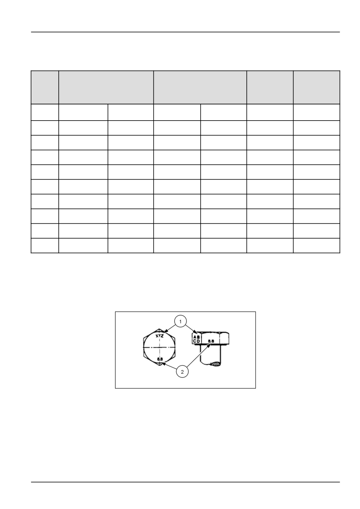
IDENTIFICATION
Metric Hex head and carriage bolts, classes 5.6 and up
20083680
1
1. Manufacturer's Identification
2. Property Class
1-7

1 - GENERAL INFORMATION
Metric Hex nuts and locknuts, classes 05 and up
20083681
2
1. Manufacturer's Identification
3. Clock Marking of Property Class and Manufacturer's
Identification (Optional), i.e. marks 60° apart indicate
2. Property Class
Class 10 properties, and marks 120° apart indicate
Class 8.
INCH NON-FLANGED HARDWARE
LOCKNUT
LOCKNUT
NOMINAL
SAE GRADE 5 BOLT
SAE GRADE 8 BOLT
GrB W/ Gr5
GrC W/ Gr8
SIZE
and NUT
and NUT
BOLT
BOLT
UN-
UN-
PLATED
PLATED
PLATED
PLATED
or
W/ZnCr
W/ZnCr
or PLATED
PLATED
GOLD
GOLD
SILVER
SILVER
8 N·m (71 lb
11 N·m (97 lb
12 N·m
16 N·m
12.2 N·m (109 lb
1/4
8.5 N·m (75 lb in)
in)
in)
(106 lb in)
(142 lb in)
in)
17 N·m
23 N·m
24 N·m
32 N·m
17.5 N·m (155 lb
25 N·m (220 lb
5/16
(150 lb in)
(204 lb in)
(212 lb in)
(283 lb in)
in)
in)
30 N·m (22 lb
40 N·m
43 N·m (31 lb
57 N·m (42 lb
3/8
31 N·m (23 lb ft)
44 N·m (33 lb ft)
ft)
(30 lb ft)
ft)
ft)
48 N·m (36 lb
65 N·m
68 N·m (50 lb
91 N·m (67 lb
7/16
50 N·m (37 lb ft)
71 N·m (53 lb ft)
ft)
(48 lb ft)
ft)
ft)
74 N·m (54 lb
98 N·m
104 N·m
139 N·m
108 N·m (80 lb
1/2
76 N·m (56 lb ft)
ft)
(73 lb ft)
(77 lb ft)
(103 lb ft)
ft)
107 N·m
142 N·m
150 N·m
201 N·m
156 N·m (115 lb
9/16
111 N·m (82 lb ft)
(79 lb ft)
(105 lb ft)
(111 lb ft)
(148 lb ft)
ft)
147 N·m
196 N·m
208 N·m
277 N·m
153 N·m (113 lb
215 N·m (159 lb
5/8
(108 lb ft)
(145 lb ft)
(153 lb ft)
(204 lb ft)
ft)
ft)
261 N·m
348 N·m
369 N·m
491 N·m
271 N·m (200 lb
383 N·m (282 lb
3/4
(193 lb ft)
(257 lb ft)
(272 lb ft)
(362 lb ft)
ft)
ft)
420 N·m
561 N·m
594 N·m
791 N·m
437 N·m (323 lb
617 N·m (455 lb
7/8
(310 lb ft)
(413 lb ft)
(438 lb ft)
(584 lb ft)
ft)
ft)
630 N·m
841 N·m
890 N·m
1187 N·m
654 N·m (483 lb
924 N·m (681 lb
1
(465 lb ft)
(620 lb ft)
(656 lb ft)
(875 lb ft)
ft)
ft)
NOTE: For Imperial Units, 1/4 in and 5/16 in hardware torque specifications are shown in pound-inches.
3/8 in
through 1 in hardware torque specifications are shown in pound-feet.
1-8
1 - GENERAL INFORMATION
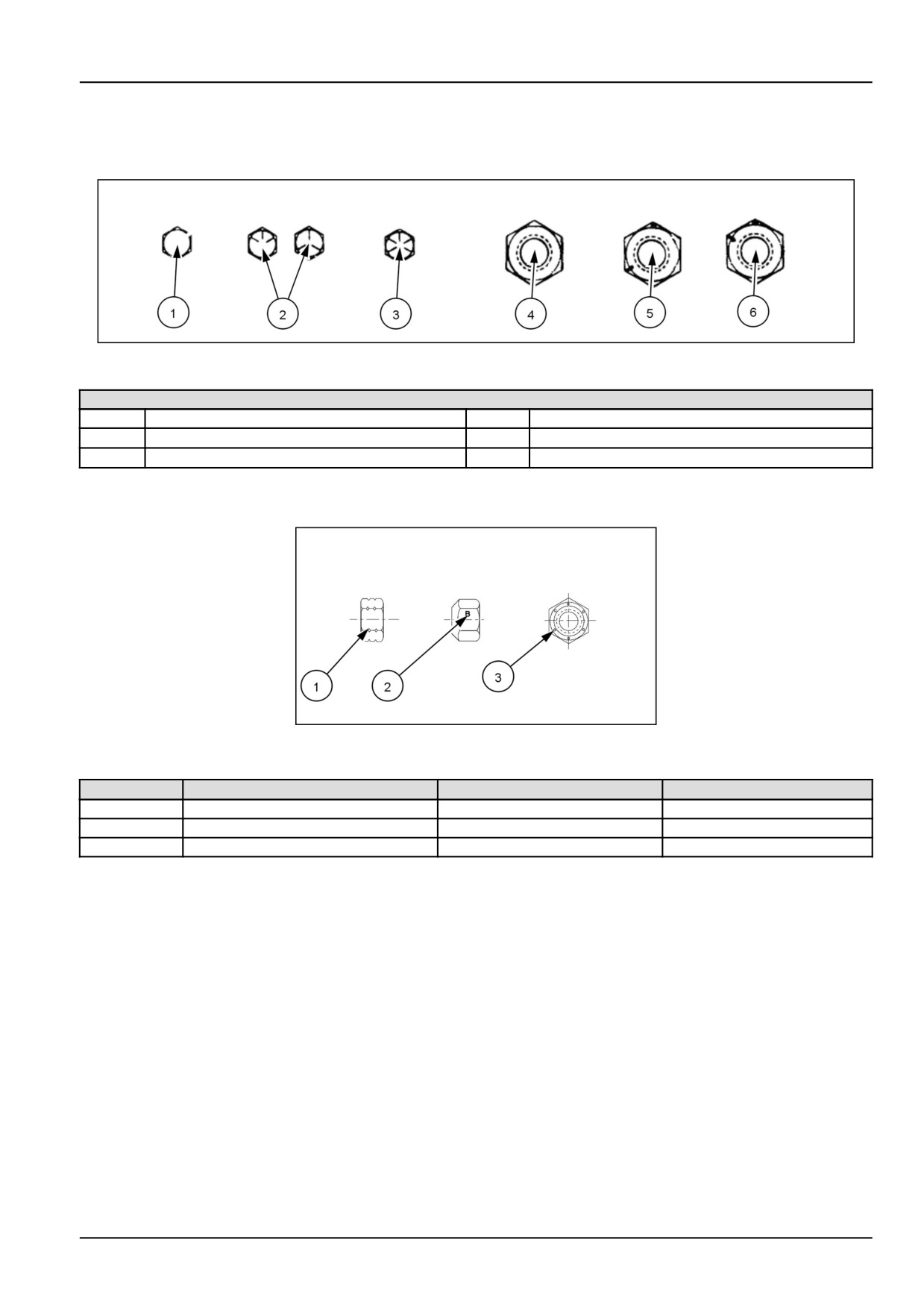
IDENTIFICATION
Inch Bolts and free-spinning nuts
20083682
3
Grade Marking Examples
SAE Grade Identification
1
Grade 2 - No Marks
4
Grade 2 Nut - No Marks
2
Grade 5 - Three Marks
5
Grade 5 Nut - Marks 120° Apart
3
Grade 8 - Five Marks
6
Grade 8 Nut - Marks 60° Apart
Inch Lock Nuts, All Metal (Three optional methods)
20090268
4
Grade Identification
Grade
Corner Marking Method (1)
Flats Marking Method (2)
Clock Marking Method (3)
Grade A
No Notches
No Mark
No Marks
Grade B
One Circumferential Notch
Letter B
Three Marks
Grade C
Two Circumferential Notches
Letter C
Six Marks
1-9
1 - GENERAL INFORMATION
Torque - Standard torque data for hydraulics
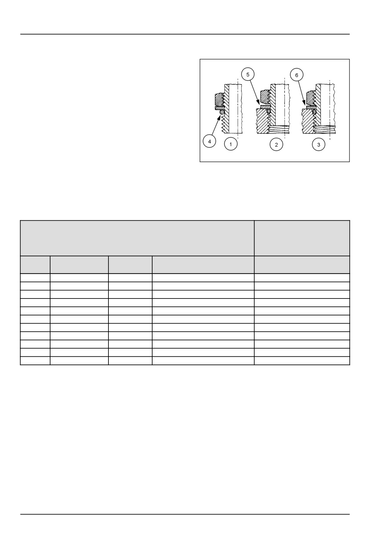
INSTALLATION OF ADJUSTABLE FITTINGS
IN STRAIGHT THREAD O RING BOSSES
1. Lubricate the O-ring by coating it with a light oil or
petroleum. Install the O-ring in the groove adjacent
to the metal backup washer which is assembled at the
extreme end of the groove (4).
2. Install the fitting into the SAE straight thread boss until
the metal backup washer contacts the face of the boss
(5).
NOTE: Do not over tighten and distort the metal
backup washer.
3. Position the fitting by turning out (counterclockwise)
23085659
1
up to a maximum of one turn. Holding the pad of the
fitting with a wrench, tighten the locknut and washer
against the face of the boss (6).
STANDARD TORQUE DATA FOR HY-
DRAULIC TUBES AND FITTINGS
TUBE NUTS FOR 37° FLARED FITTINGS
O-RING BOSS PLUGS
ADJUSTABLE FITTING
LOCKNUTS, SWIVEL
JIC- 37° SEATS
SIZE
TUBING OD
THREAD
TORQUE
TORQUE
SIZE
4
6.4 mm (1/4 in)
7/16-20
12 - 16 N·m (9 - 12 lb ft)
8 - 14 N·m (6 - 10 lb ft)
5
7.9 mm (5/16 in)
1/2-20
16 - 20 N·m (12 - 15 lb ft)
14 - 20 N·m (10 - 15 lb ft)
6
9.5 mm (3/8 in)
9/16-18
29 - 33 N·m (21 - 24 lb ft)
20 - 27 N·m (15 - 20 lb ft)
8
12.7 mm (1/2 in)
3/4-16
47 - 54 N·m (35 - 40 lb ft)
34 - 41 N·m (25 - 30 lb ft)
10
15.9 mm (5/8 in)
7/8-14
72 - 79 N·m (53 - 58 lb ft)
47 - 54 N·m (35 - 40 lb ft)
12
19.1 mm (3/4 in)
1-1/16-12
104 - 111 N·m (77 - 82 lb ft)
81 - 95 N·m (60 - 70 lb ft)
14
22.2 mm (7/8 in)
1-3/16-12
122 - 136 N·m (90 - 100 lb ft)
95 - 109 N·m (70 - 80 lb ft)
16
25.4 mm (1 in)
1-5/16-12
149 - 163 N·m (110 - 120 lb ft)
108 - 122 N·m (80 - 90 lb ft)
20
31.8 mm (1-1/4 in)
1-5/8-12
190 - 204 N·m (140 - 150 lb ft)
129 - 158 N·m (95 - 115 lb ft)
24
38.1 mm (1-1/2 in)
1-7/8-12
217 - 237 N·m (160 - 175 lb ft)
163 - 190 N·m (120 - 140 lb ft)
32
50.8 mm (2 in)
2-1/2-12
305 - 325 N·m (225 - 240 lb ft)
339 - 407 N·m (250 - 300 lb ft)
These torques are not recommended for tubes of
cleaner and apply hydraulic sealant to the 37° flare and
12.7 mm (1/2 in) OD and larger with wall thickness of
the threads.
0.889 mm (0.035 in) or less. The torque is specified
for 0.889 mm (0.035 in) wall tubes on each application
Install fitting and torque to specified torque, loosen fitting
individually.
and retorque to specifications.
Before installing and torquing 37° flared fittings, clean the
face of the flare and threads with a clean solvent or Loctite
1-10
1 - GENERAL INFORMATION
PIPE THREAD FITTING TORQUE
PIPE THREAD FITTING
Thread Size
Torque (Maximum)
Before installing and tightening pipe fittings, clean the
1/8-27
13 N·m (10 lb ft)
threads with a clean solvent or Loctite cleaner and ap-
1/4-18
16 N·m (12 lb ft)
ply sealant for all fittings including stainless steel or for
most metal fittings. For high filtration/zero contamination
3/8-18
22 N·m (16 lb ft)
systems use .
1/2-14
41 N·m (30 lb ft)
3/4-14
54 N·m (40 lb ft)
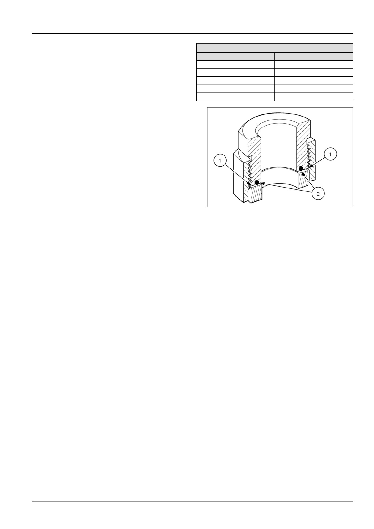
INSTALLATION OF ORFS (O-RING FLAT
FACED) FITTINGS
When installing ORFS fittings thoroughly clean both flat
surfaces of the fittings (1) and lubricate the O-ring (2) with
light oil. Make sure both surfaces are aligned properly.
Torque the fitting to specified torque listed throughout the
repair manual.
NOTICE: If the fitting surfaces are not properly cleaned,
the O-ring will not seal properly. If the fitting surfaces are
not properly aligned, the fittings may be damaged and will
not seal properly.
NOTICE: Always use genuine factory replacement oils
50011183
2
and filters to ensure proper lubrication and filtration of en-
gine and hydraulic system oils.
The use of proper oils, grease, and keeping the hydraulic
system clean will extend machine and component life.
1-11
1 - GENERAL INFORMATION
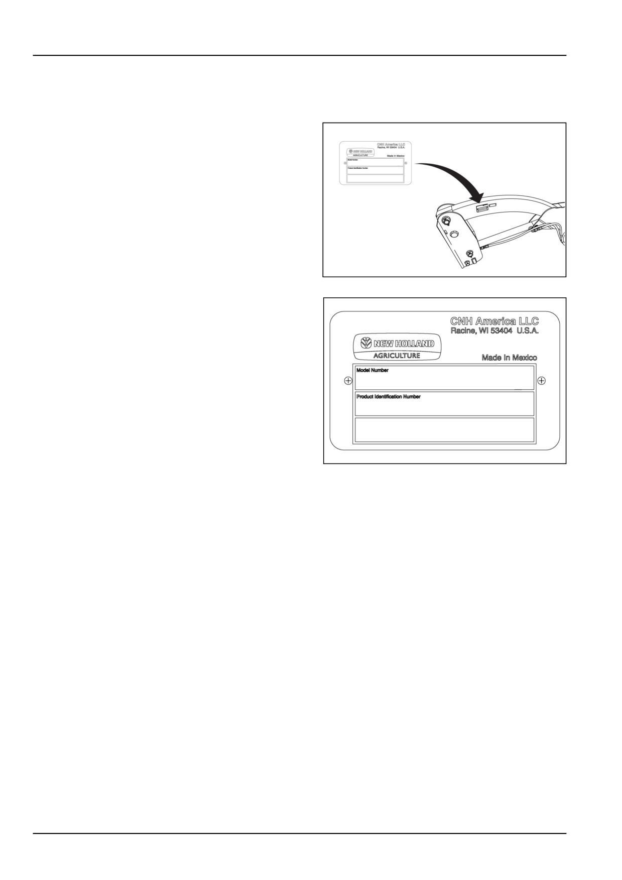
Product identification
PRODUCT IDENTIFICATION PLATE
A product identification plate is located on the inside of the
left-hand loader frame.
NHIL15CT00501AA
1
The identification numbers on this plate are important in
the event that your loader should require future service.
36086829
2
1-12
1 - GENERAL INFORMATION
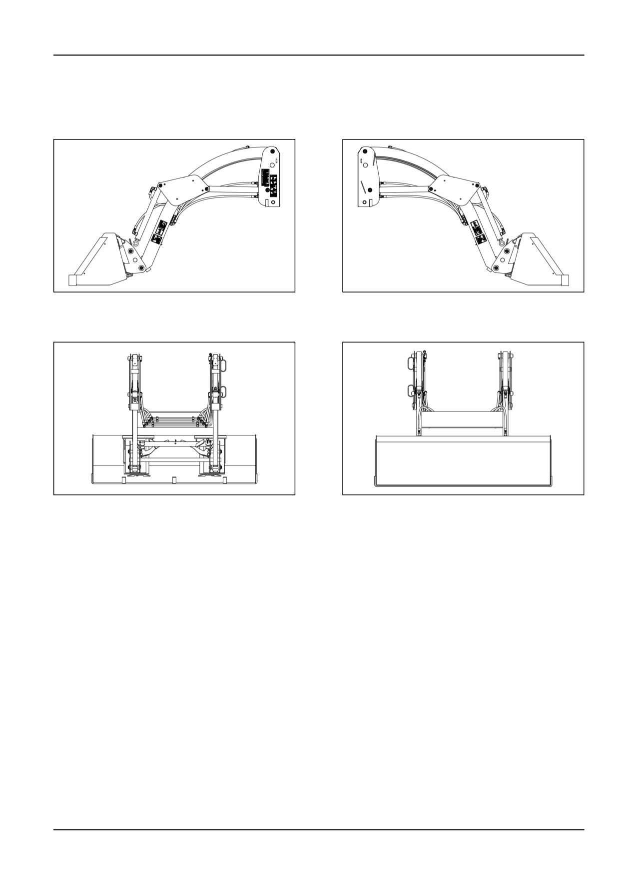
Machine orientation
NOTE: On this equipment, left-hand and right-hand are
determined by standing behind the unit, looking in the di-
rection of travel.
NHIL15CT00502AA
1
NHIL15CT00503AA
2
Left-hand view
Right-hand view
NHIL15CT00505AA
3
NHIL15CT00504AA
4
Rear view
Front view
1-13
1 - GENERAL INFORMATION
Product overview
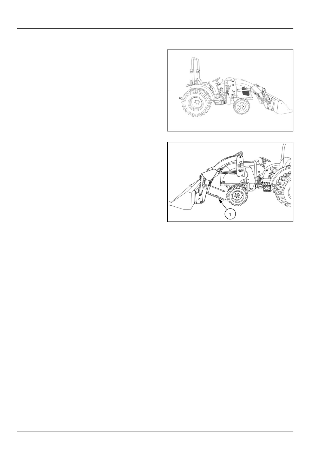
The 140TL loader is designed to be compatible with the
Workmaster™ Hydro-Static Transmission (HST) or me-
chanical transmission compact tractors.
NHIL16CT02175FA
1
The loader is a quick attach unit, and no tools are required
to mount or dismount the loader from the tractor. The
loader also has its own park stand (1).
A pallet fork and a complete line of heavy duty and ma-
terial buckets is available. As the capacities of the buck-
ets have been matched to tractor size, the operator can
choose the bucket best suited for the tractor and the job.
Bucket recommendations are listed in the Specifications
section of this manual.
NHIL15CT00489AA
2
1-14
2 - SAFETY INFORMATION
2 - SAFETY INFORMATION###_2_###
Safety rules and signal word definitions
Personal safety
This is the safety alert symbol. It is used to alert you to potential personal injury hazards. Obey all
safety messages that follow this symbol to avoid possible death or injury.
Throughout this manual and on machine safety signs, you will find the signal words DANGER, WARNING, and CAU-
TION followed by special instructions. These precautions are intended for the personal safety of you and those
working with you.
Read and understand all the safety messages in this manual before you operate or service the machine.
DANGER indicates a hazardous situation that, if not avoided, will result in death or serious injury. The color
associated with DANGER is RED.
WARNING indicates a hazardous situation that, if not avoided, could result in death or serious injury. The color
associated with WARNING is ORANGE.
CAUTION indicates a hazardous situation that, if not avoided, could result in minor or moderate injury. The
color associated with CAUTION is YELLOW.
FAILURE TO FOLLOW DANGER, WARNING, AND CAUTION MESSAGES COULD RESULT
IN DEATH OR SERIOUS INJURY.
Machine safety
NOTICE: Notice indicates a situation that, if not avoided, could result in machine damage or property damage. The
color associated with Notice is BLUE.
Throughout this manual you will find the signal word Notice followed by special instructions to prevent machine dam-
age or property damage. The word Notice is used to address practices not related to personal safety.
Information
NOTE: Note indicates additional information that clarifies steps, procedures, or other information in this manual.
Throughout this manual you will find the word Note followed by additional information about a step, procedure, or
other information in the manual. The word Note is not intended to address personal safety or property damage.
2-1
2 - SAFETY INFORMATION
Safety rules
General safety rules
Use caution when you operate the machine on slopes.
Keep clear of moving parts. Loose clothing, jewelry,
Raised equipment, full tanks and other loads will change
watches, long hair, and other loose or hanging items can
the center of gravity of the machine. The machine can
become entangled in moving parts.
tip or roll over when near ditches and embankments or
uneven surfaces.
Wear protective equipment when appropriate.
Never permit anyone other than the operator to ride on
DO NOT attempt to remove material from any part of the
the machine.
machine while it is being operated or while components
are in motion.
Never operate the machine under the influence of alcohol
or drugs, or while you are otherwise impaired.
Make sure that all guards and shields are in good con-
dition and properly installed before you operate the ma-
When digging or using ground-engaging attachments, be
chine. Never operate the machine with shields removed.
aware of buried cables. Contact local utilities to determine
Always close access doors or panels before you operate
the locations of services.
the machine.
Pay attention to overhead power lines and hanging obsta-
Dirty or slippery steps, ladders, walkways, and platforms
cles. High voltage lines may require significant clearance
can cause falls. Make sure these surfaces remain clean
for safety.
and clear of debris.
Hydraulic oil or diesel fuel leaking under pressure can
A person or pet within the operating area of a machine can
penetrate the skin, causing serious injury or infection.
be struck or crushed by the machine or its equipment. DO
NOT allow anyone to enter the work area.
• DO NOT use your hand to check for leaks. Use a piece
of cardboard or paper.
Raised equipment and/or loads can fall unexpectedly and
• Stop the engine, remove the key, and relieve the pres-
crush persons underneath. Never allow anyone to enter
sure before you connect or disconnect fluid lines.
the area underneath raised equipment during operation.
• Make sure that all components are in good condition.
Always keep windows, mirrors, all lighting, and
Tighten all connections before you start the engine or
Slow-Moving Vehicle (SMV) emblem clean to provide the
pressurize the system.
best possible visibility while you operate the machine.
• If hydraulic fluid or diesel fuel penetrates the skin, seek
medical attention immediately.
Operate controls only when seated in the operator’s seat,
except for those controls expressly intended for use from
• Continuous long term contact with hydraulic fluid may
other locations.
cause skin cancer. Avoid long term contact and wash
the skin promptly with soap and water.
2-2
2 - SAFETY INFORMATION
Before you leave the machine:
1. Bring the engine to low idle speed.
1. Park the machine on a firm, level surface.
2. Disengage all drive systems.
2. Put all controls in neutral or park lock position.
3.
WARNING
3. Engage the parking brake. Use wheel chocks if re-
Some components may continue to run down
quired.
after you disengage drive systems.
Make sure all drive systems are fully disen-
4. Lower all hydraulic equipment — Implements, header,
gaged.
etc.
Failure to comply could result in death or seri-
5. Turn off the engine and remove the key.
ous injury.
W0113A
When, due to exceptional circumstances, you would
decide to keep the engine running after you leave
Shift the transmission into neutral.
the operator’s station, then you must follow these
4. Apply the parking brake.
precautions:
General maintenance safety
Keep the area used for servicing the machine clean and
pressure to escape before you completely remove the
dry. Clean up spilled fluids.
cap.
Service the machine on a firm, level surface.
Replace damaged or worn tubes, hoses, electrical wiring,
etc.
Install guards and shields after you service the machine.
The engine, transmission, exhaust components, and hy-
Close all access doors and install all panels after servicing
draulic lines may become hot during operation. Take care
the machine.
when you service such components. Allow surfaces to
cool before you handle or disconnect hot components.
Do not attempt to clean, lubricate, clear obstructions, or
Wear protective equipment when appropriate.
make adjustments to the machine while it is in motion or
while the engine is running.
When welding, follow the instructions in the manual. Al-
ways disconnect the battery before you weld on the ma-
Always make sure that working area is clear of tools,
chine. Always wash your hands after you handle battery
parts, other persons and pets before you start operating
components.
the machine.
Make sure that tires are correctly inflated. Do not exceed
Unsupported hydraulic cylinders can lose pressure and
any recommended load or pressure. Follow the instruc-
drop the equipment, causing a crushing hazard. Do not
tions in the manual for proper tire inflation.
leave equipment in a raised position while parked or dur-
ing service, unless the equipment is securely supported.
Tires are heavy. Handling tires without proper equipment
could cause death or serious injury.
Jack or lift the machine only at jack or lift points indicated
in this manual.
Never weld on a wheel with a tire installed. Always re-
move the tire completely from the wheel prior to welding.
Incorrect towing procedures can cause accidents. When
you tow a disabled machine follow the procedure in this
Always have a qualified tire technician service the tires
manual. Use only rigid tow bars.
and wheels. If a tire has lost all pressure, take the tire and
wheel to a tire shop or your dealer for service. Explosive
Stop the engine, remove the key, and relieve pressure
separation of the tire can cause serious injury.
before you connect or disconnect fluid lines.
DO NOT weld to a wheel or rim until the tire is completely
Stop the engine and remove the key before you connect
removed. Inflated tires can generate a gas mixture with
or disconnect electrical connections.
the air that can be ignited by high temperatures from weld-
ing procedures performed on the wheel or rim. Removing
Scalding can result from incorrect removal of coolant
the air or loosening the tire on the rim (breaking the bead)
caps. Cooling systems operate under pressure. Hot
will NOT eliminate the hazard. This condition can exist
coolant can spray out if you remove a cap while the sys-
whether tires are inflated or deflated. The tire MUST be
tem is hot. Allow the system to cool before you remove
completely removed from the wheel or rim prior to weld-
the cap. When you remove the cap, turn it slowly to allow
ing the wheel or rim.
Driving on public roads and general transportation safety
Comply with local laws and regulations.
Use appropriate lighting to meet local regulations.
2-3
2 - SAFETY INFORMATION
Make sure that the SMV emblem is visible.
Be aware of overhead structures or power lines and make
sure that the machine and/or attachments can pass safely
Make sure that the brake pedal latch is engaged. You
under.
must lock brake pedals together for road travel.
Travel speed should be such that you maintain complete
Use safety chains for trailed equipment when safety
control and machine stability at all times.
chains are provided with machine or equipment.
Slow down and signal before turning.
Lift implements and attachments high enough above
ground to prevent accidental contact with road.
Pull over to allow faster traffic to pass.
When you transport equipment or a machine on a trans-
Follow correct towing procedure for equipment with or
port trailer, make sure that it is properly secured. Be sure
without brakes.
the SMV on the equipment or machine is covered while
being transported on a trailer.
Seat belts
Seat belts must be worn at all times.
• Check that bolts are tight on the seat bracket or mount-
ing.
Seat belt inspection and maintenance:
• If the belt is attached to the seat, make sure that the
• Keep seat belts in good condition.
seat or seat brackets are mounted securely.
• Keep sharp edges and items than can cause damage
• Keep seat belts clean and dry.
away from the belts.
• Clean belts only with soap solution and warm water.
• Periodically check belts, buckles, retractors, tethers,
• Do not use bleach or dye on the belts because this can
slack take-up system, and mounting bolts for damage
make the belts weak.
and wear.
• Replace all parts that have damage or wear.
• Replace belts that have cuts that can make the belt
weak.
2-4
2 - SAFETY INFORMATION
Personal Protective Equipment (PPE)
Wear Personal Protective Equipment (PPE) such as hard
hat, eye protection, heavy gloves, hearing protection, pro-
tective clothing, etc.
Do Not Operate tag
Before you start servicing the machine, attach a ‘Do Not
Operate’ warning tag to the machine in an area that will
be visible.
Hazardous chemicals
If you are exposed to or come in contact with hazardous
MSDS, and on manufacturer containers, as well as the in-
chemicals you can be seriously injured. The fluids, lu-
formation in this manual, when you service the machine.
bricants, paints, adhesives, coolant, etc. required for the
function of your machine can be hazardous. They may
Dispose of all fluids, filters, and containers in an environ-
be attractive and harmful to domestic animals as well as
mentally safe manner according to local laws and regula-
humans.
tions. Check with local environmental and recycling cen-
ters or your dealer for correct disposal information.
Material Safety Data Sheets (MSDS) provide information
about the chemical substances within a product, safe
Store fluids and filters in accordance with local laws and
handling and storage procedures, first aid measures, and
regulations. Use only appropriate containers for the stor-
procedures to take in the event of a spill or accidental
age of chemicals or petrochemical substances.
release. MSDS are available from your dealer.
Keep out of reach or children or other unauthorized per-
Before you service your machine check the MSDS for
sons.
each lubricant, fluid, etc. used in this machine. This in-
Applied chemicals require additional precautions. Obtain
formation indicates the associated risks and will help you
service the machine safely. Follow the information in the
complete information from the manufacturer or distributor
of the chemicals before you use them.
Utility safety
When digging or using ground-engaging equipment, be
power source occur, the following precautions must be
aware of buried cables and other services. Contact your
taken:
local utilities or authorities, as appropriate, to determine
• Stop the machine movement immediately.
the locations of services.
• Apply the parking brake, stop the engine, and remove
Make sure that the machine has sufficient clearance to
the key.
pass in all directions. Pay special attention to overhead
• Check if you can safely leave the cab or your actual po-
power lines and hanging obstacles. High voltage lines
sition without contact with electrical wires. If not, stay
may require significant clearance for safety. Contact local
in your position and call for help. If you can leave your
authorities or utilities to obtain safe clearance distances
position without touching lines, jump clear of the ma-
from high voltage power lines.
chine to make sure that you do not make contact with
the ground and the machine at the same time.
Retract raised or extended components, if necessary.
Remove or lower radio antennas or other accessories.
• Do not permit anyone to touch the machine until power
Should a contact between the machine and an electric
has been shut off to the power lines.
Electrical storm safety
Do not operate machine during an electrical storm.
If an electrical storm should strike during operation, re-
main in the cab. Do not leave the cab or operator’s plat-
If you are on the ground during an electrical storm, stay
form. Do not make contact with the ground or objects
away from machinery and equipment. Seek shelter in a
outside the machine.
permanent, protected structure.
2-5
2 - SAFETY INFORMATION
Mounting and dismounting
Mount and dismount the machine only at designated lo-
Maintain a three-point contact with steps, ladders, and
cations that have handholds, steps, and/or or ladders.
handholds.
Do not jump off of the machine.
Never mount or dismount from a moving machine.
Make sure that steps, ladders, and platforms remain
Do not use the steering wheel or other controls or acces-
clean and clear of debris and foreign substances. Injury
sories as handholds when you enter or exit the cab or
may result from slippery surfaces.
operator’s platform.
Face the machine when you mount and dismount the ma-
chine.
Working at heights
When the normal use and maintenance of the machine
• Do not stand on surfaces that are not designated as
requires you to work at heights:
steps or platforms.
• Correctly use installed steps, ladders, and railings.
Do not use the machine as a lift, ladder, or platform for
• Never use ladders, steps, or railings while the machine
working at heights.
is moving.
Lifting and overhead loads
Never use loader buckets, forks, etc. or other lifting, han-
Loader buckets, forks, etc. or other lifting, handling, or
dling, or digging equipment to lift persons.
digging equipment and its load will change the center of
gravity of the machine. This can cause the machine to tip
Do not use raised equipment as a work platform.
on slopes or uneven ground.
Know the full area of movement of the machine and equip-
Load items can fall off the loader bucket or lifting equip-
ment and do not enter or permit anyone to enter the area
ment and crush the operator. Care must be taken when
of movement while the machine is in operation.
lifting a load. Use proper lifting equipment.
Never enter or permit anyone to enter the area under-
Do not lift load higher than necessary. Lower loads to
neath raised equipment. Equipment and/or loads can fall
transport. Remember to leave appropriate clearance to
unexpectedly and crush persons underneath it.
the ground and other obstacles.
Do not leave equipment in raised position while parked
Equipment and associated loads can block visibility and
or during service, unless securely supported. Hydraulic
cause an accident. Do not operate with insufficient visi-
cylinders must be mechanically locked or supported if
bility.
they are left in a raised position for service or access.
2-6
2 - SAFETY INFORMATION
Precautionary Statements
A careful operator is the best operator. Most accidents can be avoided by observing certain precautions. To help
prevent accidents, read the following precautions before operating this equipment. Equipment should be operated
only by those who are responsible and instructed to do so.
Carefully review the procedures given in this manual with all operators. It is important that all operators be familiar
with and follow safety precautions.
General
2. Do not lift or carry anybody on the loader or in the
bucket or attachment.
1. Read the Operator's Manual carefully before using the
3. Never allow anyone to get under the loader bucket or
tractor or loader. Lack of operating knowledge can
reach through the lift arms when the bucket is raised.
lead to accidents.
4. Do not walk or work under a raised loader, bucket,
2. Replace damaged or illegible safety decals. See the
or attachment unless it is securely blocked or held in
Specifications section of this manual for required de-
position.
cals.
5. Avoid overhead wires and obstacles when the loader
3. Operate the tractor and loader only from the operator's
is raised. Contacting electrical lines can cause elec-
seat.
trocution.
The Tractor
6. Make sure all dismounted loaders are on a hard, level
surface.
1. Use an approved roll bar and seat belt for safe opera-
7. Do not repair, remove, or replace any parts of the
tion. Overturning a tractor without a roll bar can result
loader while it is in the dismounted position.
in death or injury. If your tractor is not equipped with a
roll bar and seat belt, see your tractor dealer.
Operating the Loader
2. Equip your tractor with FOPS (Falling Object Protec-
tive Structure) and seat belts before installing or oper-
1. It is the loader owner's responsibility to be certain that
ating the loader.
anyone operating the loader reads this manual first to
be aware of the safe way of operating the loader.
3. Use the loader only on a tractor with the ROPS in-
stalled. Whenever possible, operate the tractor and
2. Exercise caution when operating the loader with a
loader with the ROPS in the upright and locked posi-
raised, loaded bucket or fork.
tion and the seat belt fastened and correctly adjusted.
3. Avoid loose fill, rocks, and holes. They can be dan-
When operating in restricted overhead environment
gerous for loader operation or movement.
with the ROPS folded down, do not wear the seat belt.
Always return the ROPS to the upright and locked po-
4. Use care to maintain proper stability when operating
sition as soon as operating conditions permit.
on steep grades. Always carry the bucket in the low-
est position possible.
4. Add the recommended wheel ballast and/or rear
weight as recommended in the owner's manual to
5. Allow for the loader length when making turns.
provide good stability.
6. Stop the loader arms gradually when lowering or lift-
5. Move the wheels to the tractor manufacturer's widest
ing.
recommended settings to increase stability.
7. Use caution when handling loose or shiftable loads.
6. Move and turn the tractor at low speeds.
8. Carry the bucket at a low position during transport for
better visibility.
The Loader
9. When parking or servicing, lower the bucket to the
ground, stop the engine, and set the park brakes be-
1. Improper use of a loader can cause serious injury or
fore leaving the tractor seat.
death.
2-7
2 - SAFETY INFORMATION
10.
Operate the loader controls only when properly
Maintenance
seated at the controls.
1.
When servicing or replacing the pins in the cylinder
11.
Using front end loaders without special attachments
ends, bucket, etc., always use a brass drift and ham-
for handling large heavy objects such as large round
mer. Failure to do so could result in injury from flying
or rectangular bales, logs, and oil drums is NOT
metal fragments.
RECOMMENDED.
2.
Do not modify or alter, or permit anyone else to modify
12.
Handling large heavy objects can be extremely
or alter, the loader or any of its components or any
dangerous due to:
loader function without first consulting a New Holland
• danger of rolling the tractor over.
dealer. If you have any questions regarding loader
modifications, contact New Holland .
• danger of upending the tractor.
3.
Always wear safety goggles when servicing or repair-
• danger of the object rolling or sliding down the
ing the machine.
loader arms onto the operator.
4.
Escaping hydraulic/diesel fluid under pressure can
13.
If you must perform this sort of work (see #12
penetrate the skin, causing serious injury.
above), protect yourself by:
• DO NOT use your hand to check for leaks.
• using the proper attachment.
• Use a piece of cardboard or paper to search for
• never lifting the load higher than necessary to clear
leaks.
the ground when moving.
• Stop the engine and relieve the pressure before
• ballasting the tractor rear to compensate for the
connecting or disconnecting the hydraulic or diesel
load.
lines.
• never lifting large objects with equipment that does
• Tighten all connections before starting the engine or
not have an anti-rollback device.
pressuring the lines.
• moving slowly and carefully, avoiding rough ter-
• If any fluid is injected into the skin, obtain medical
rain.
attention IMMEDIATELY or gangrene may result.
14.
Loader lift capacity and break-away capacity dimin-
5.
Do not tamper with the relief valve setting. The relief
ish as the loader height is increased. Use care not
valve is preset at the factory. Changing the setting can
to grasp more material than the loader is designed to
cause overloading the loader and tractor, and serious
handle.
operator injury may result.
This is the safety alert symbol. It is used to alert you to potential personal injury hazards.
Obey all safety messages that follow this symbol to avoid possible injury or death.
2-8
2 - SAFETY INFORMATION
Safety signs
Safety signs are placed on your machine as a guide for your safety. Walk around the machine and note the content
and location of these decals before operating your machine
Following is a listing of Safety signs and locations. Read and understand them before operating the machine
Safety sign inspection and maintenance:
1. Cleaning Safety signs
1. Keep Safety signs clean and legible.
2. Use a soft cloth, water, and a gentle detergent.
3. Do not use solvent, gasoline or other harsh chemicals to clean Safety signs. Solvents, gasoline, and other
harsh chemicals may damage or remove Safety signs.
2. Replace all Safety signs that are damaged, missing, painted over or illegible. See your NEW HOLLAND dealer
for replacement Safety signs.
3. If a Safety sign is on a part that is replaced, make sure the Safety sign is installed on the new part.
Universal or informational Safety signs
Decals which display the “Read Operator’s Manual” symbol are intended to direct the operator to the Operator’s
Manual for further information regarding maintenance, adjustments, and/or procedures for particular areas of the
machine. When a Safety sign displays this symbol
refer to the appropriate page of the Operator’s Manual.
2-9
2 - SAFETY INFORMATION
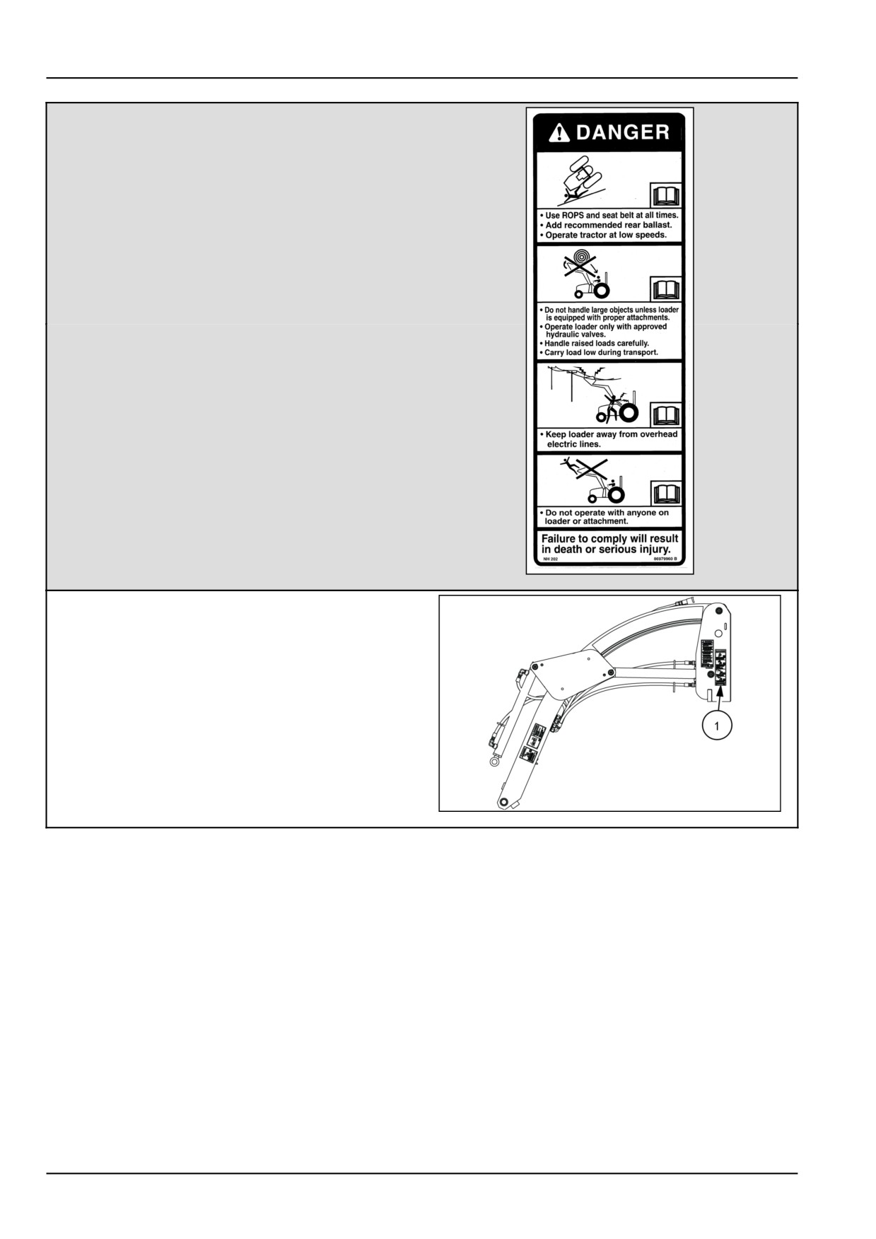
DANGER
Use ROPS and seat belt at all times.
Add recommended rear ballast.
Operate tractor at low speeds.
Do not handle large objects unless tractor is
equipped with proper attachments.
Operate loader only with approved hydraulic valves.
Handle raised loads carefully.
Carry loads low during transport.
Keep loader away from overhead electric lines.
Do not operate with anyone on loader or attachment.
Failure to comply will result in death or serious
injury.
Quantity 1
English 86979960
French 87045261
86979960B
1
(1) Left-hand side, outside face of mount upright
NHIL15CT00499AA
2
2-10
2 - SAFETY INFORMATION
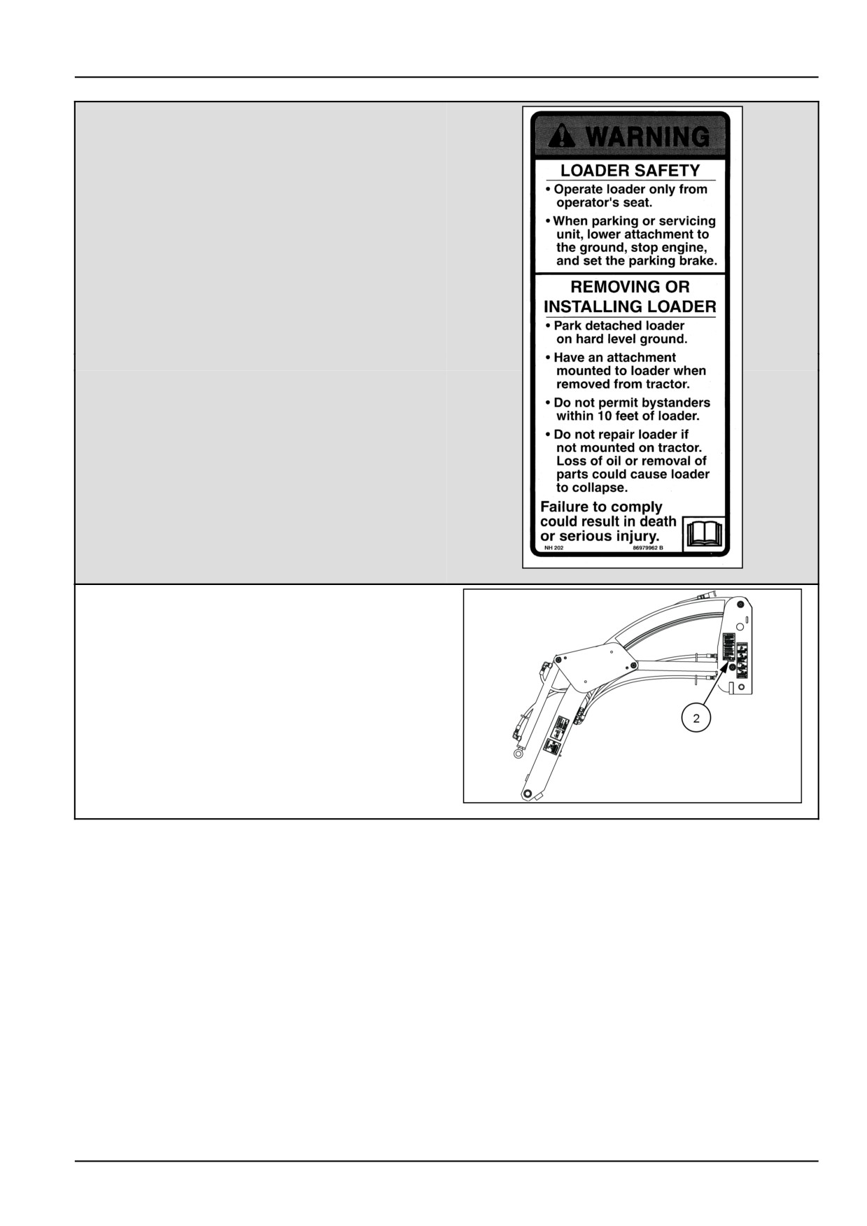
WARNING
LOADER SAFETY
Operate loader only from operator's seat.
When parking or servicing unit, lower the bucket to
the ground, stop engine, and set the parking brake.
REMOVING OR INSTALLING LOADER.
Park detached loader on hard level ground.
Have an attachment mounted to loader when
removed from tractor.
Do not permit bystanders within 10 feet of loader.
Do not repair loader if it is not mounted on tractor.
Loss of oil or removal of parts could cause loader
to collapse.
Failure to comply could result in death or serious
injury.
Quantity 1
English 86979962
French 87045260
86979962B
3
(2) Left-hand side rear of mount upright.
NHIL15CT00499AA
4
2-11
2 - SAFETY INFORMATION
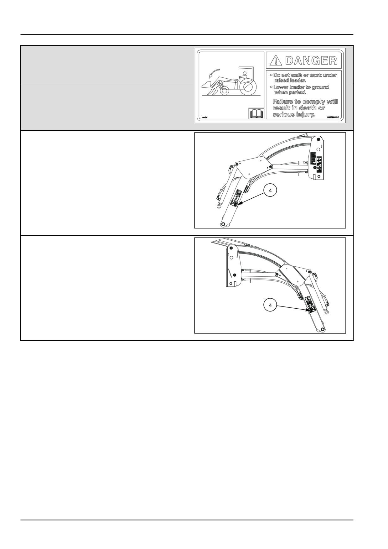
Danger
Do not walk or work under raised loader.
Lower loader to ground when parked.
Failure to comply will result in death or serious
injury.
Quantity 2
English 86979961
French 87045259
86979961
5
(4) Left-hand side loader boom.
NHIL15CT00499AA
6
(4) Right-hand side loader boom.
NHIL15CT00498AA
7
2-12
2 - SAFETY INFORMATION
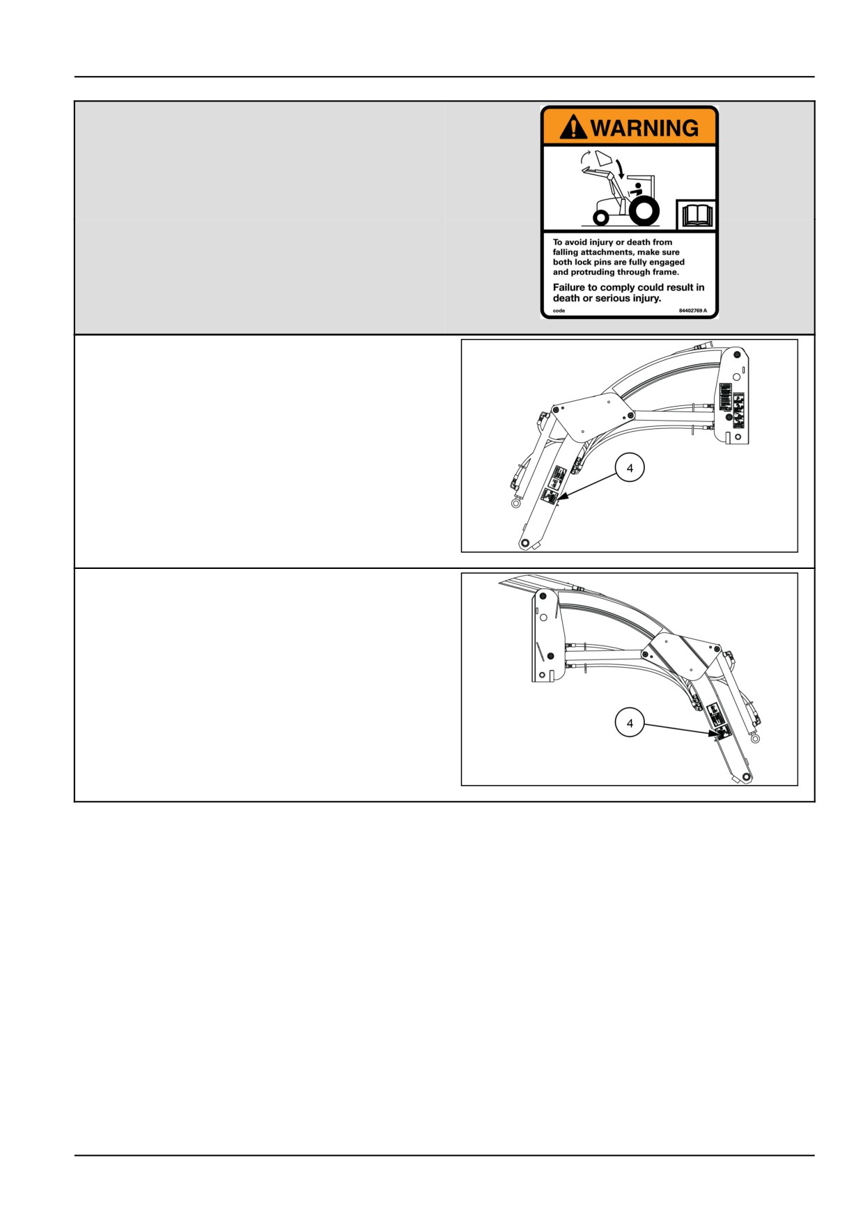
WARNING
To avoid injury or death from
falling attachments, make sure
both lock pins are fully engaged
and protruding through frame.
Failure to comply could result in death or serious
injury.
Quantity 2
English 84402769
French 47510444
84402769
8
(4) Left-hand side loader boom.
NHIL15CT00499AA
9
(4) Right-hand side loader boom.
NHIL15CT00498AA
10
2-13
2 - SAFETY INFORMATION
Safety features
See 1-14 for safety feature description of the park stand.
2-14
3 - OPERATING INSTRUCTIONS
3 - OPERATING INSTRUCTIONS###_4_###
COMMISSIONING THE UNIT
Machine preparation
Machine Preparation
WARNING
Improper operation or service of this machine can result in an accident.
Read and understand the SAFETY INFORMATION Section before you perform any maintenance, ser-
vice, or repairs. Read and understand the specific service procedures for the components you plan
to work with before you start servicing the machine.
Failure to comply could result in death or serious injury.
W0138A
Inspection
Thoroughly inspect the fully assembled loader and tractor prior to operation
1. Check all hardware to ensure that it has been properly installed and tightened. Check that the hardware is tight
after the first 10 hours of operation and every 50 hours thereafter.
2. Check the tire pressure. Refer to the Specifications section of this manual for recommended pressures.
3. Review the lubrication schedule to be certain that all pivot points have been properly lubricated.
4. Inspect all hose and tubing connections for leaks.
Installing Counterbalance
WARNING
Roll-over hazard!
Before operating a tractor with a loader, ballast the tractor-loader combination so that a minimum of
25 percent of the total weight is on the rear wheels, with the rated load in the bucket in maximum
forward position.
Failure to comply could result in death or serious injury.
W0291A
Sufficient weight can be added to the tractor by filling the rear tires with liquid ballast, or by installing a three-point hitch
counterweight. If three-point hitch counterweight is used, carry it as low as possible at all times to maximize stability.
The effective counterbalance weight of mounted rear equipment is determined by multiplying the actual weight of the
equipment by 1.50.
EXAMPLE: If equipment weighing 400 lbs is attached to the rear of the tractor, multiply 400 lbs by 1.50. This equals
600 lbs of effective counterbalance weight.
Make sure that the FOPS (Falling Object Protective Structure) is installed.
Refer to the counterbalance chart in the Specifications section of this manual.
3-1
3 - OPERATING INSTRUCTIONS
Installing the loader
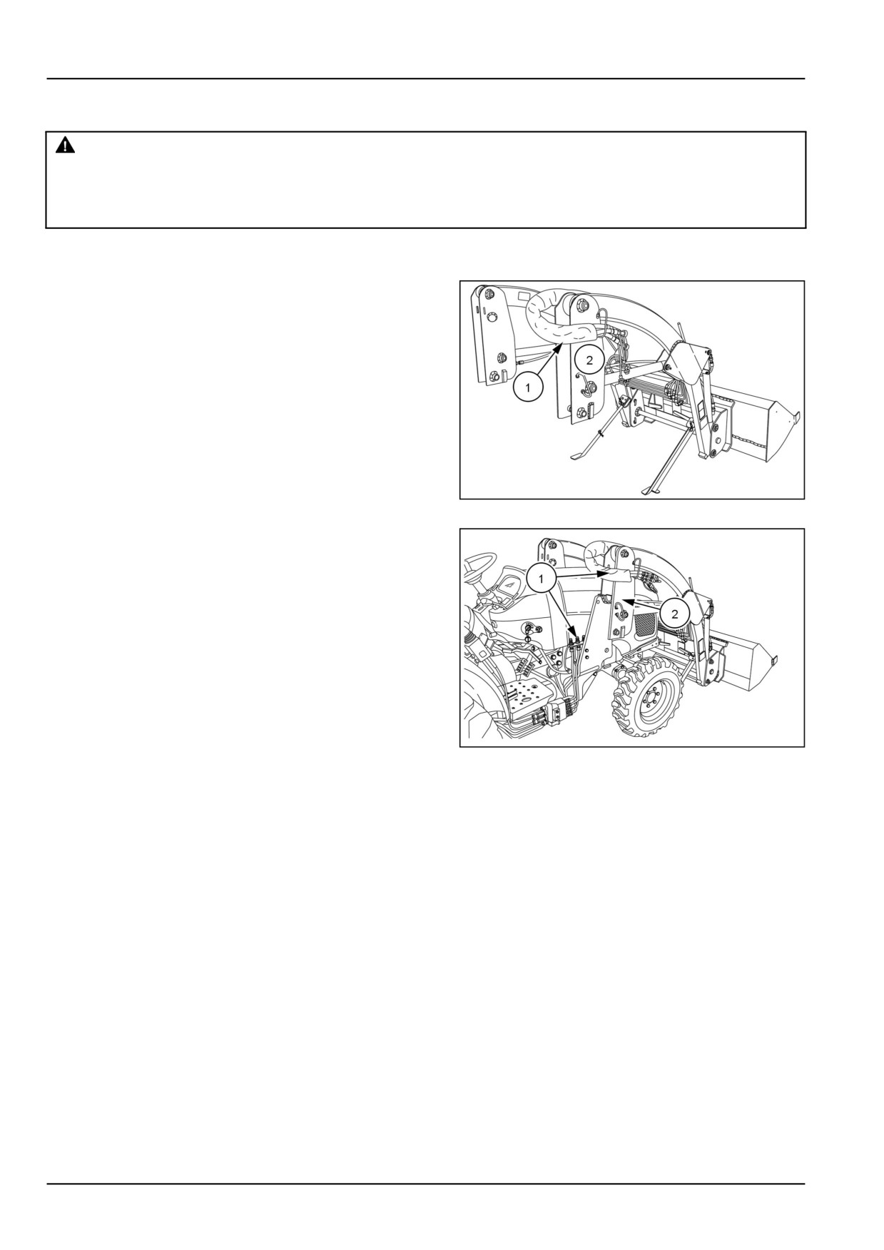
WARNING
Crushing hazard!
Never stand between the front of the tractor and the loader cross tubes.
Failure to comply could result in death or serious injury.
W1075A
Preparing to install the loader
1. Pull the hydraulic hoses (1), to the outside of the loader
frame (2), so as not to damage them during the instal-
lation of the loader.
NHIL16CT02003AA
1
2. Start the tractor engine and release the parking brake.
3. Slowly drive the tractor squarely into the loader (2) until
the loader is close enough to connect the hydraulic
hoses (1) without pulling strain on the hydraulic hoses.
4. Engage the tractor brakes and turn off the engine.
5. Connect the hydraulic hoses.
NHIL16CT02166AA
2
Hydraulic hose connection
NOTE: See 3-6
3-2
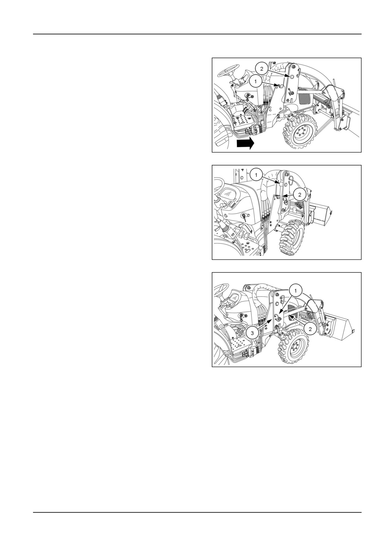
3 - OPERATING INSTRUCTIONS
Installation of the loader
1. Start the tractor engine, release the brakes, and slowly
drive the tractor forward until the tower saddle pins (2),
are just forward and above the mount bracket saddles
(1).
NHIL16CT02172AA
3
2. Gradually activate the bucket control lever to extend
the bucket cylinders which will direct the tower saddle
pin (1) down into the mount bracket saddle (2).
NHIL16CT02173AA
4
3. Gradually activate the lift control lever to extend the lift
cylinders (2) until the stop plates (1) are in contact with
the loader mount bracket saddles (3).
4. When the tower saddle pins are fully engaged with the
mount bracket saddles, engage the tractor brakes and
shut off the engine.
NHIL16CT02174AA(1)
5
3-3
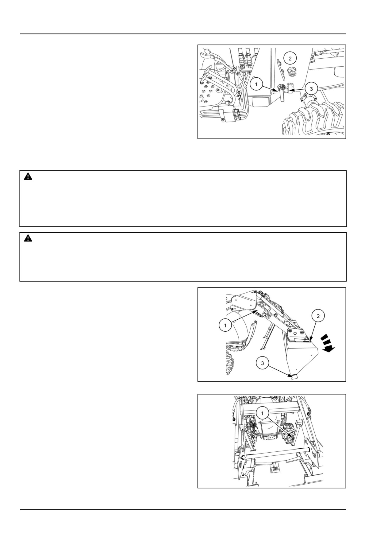
3 - OPERATING INSTRUCTIONS
5. Install the pins (1) from the outside side of loader frame
(2).
6. Secure the pins with the safety pins (3).
NOTICE: Repeat this step for the opposite side.
NHIL16CT02165AA
6
Stowing the park stand
WARNING
Avoid injury!
To install or remove the park stand, raise the loader and then set the loader down on its cutting edge
(the bottom surface of the bucket should be vertical).This safely supports the boom while the operator
installs or removes the park stand.
Failure to comply could result in death or serious injury.
W1248A
WARNING
Crushing hazard!
Make sure the bucket or attachment is resting on the ground before folding or unfolding loader sup-
port legs.
Failure to comply could result in death or serious injury.
W0122A
1. Raise the loader boom and lower the bucket (1) in the
extended, dump position, with the bucket cutting edge
(2) resting on the ground.
2. Shut off the engine on the tractor and set the parking
brake.
NHIL15CT00495AA
7
3. Remove the center stow pin safety pin (1).
NHIL15CT00496AA
8
3-4
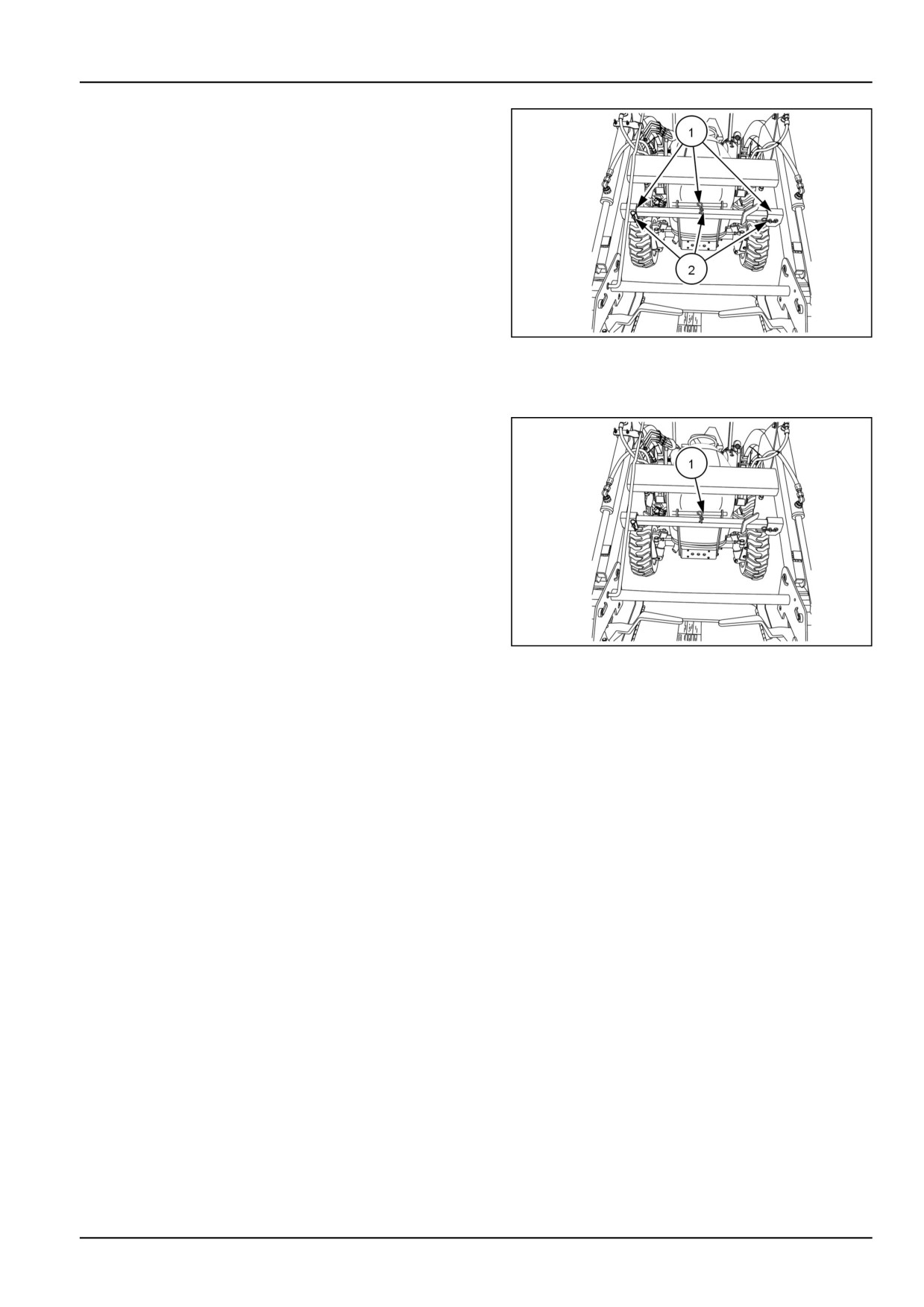
3 - OPERATING INSTRUCTIONS
4. Remove the clips (1) and pins (2) from the loader sup-
port legs (3) and fold the legs up into the stowed posi-
tion.
NHIL15CT00497AA
9
NOTE: The right side support leg MUST be folded up prior
to the left side, to allow for proper stowage..
5. Install the center stow pin safety pin (1).
NHIL15CT00497AA
10
3-5
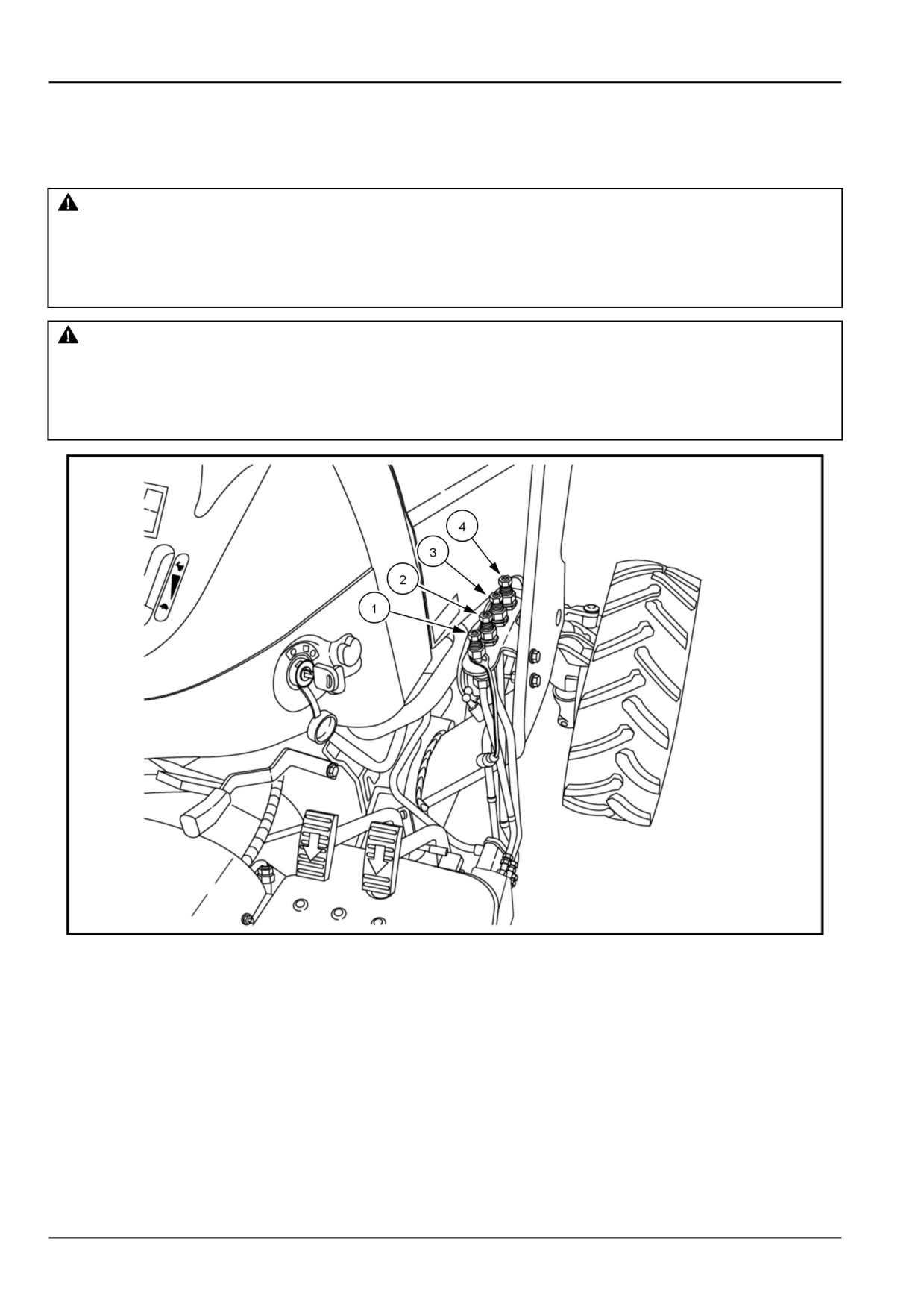
3 - OPERATING INSTRUCTIONS
Connecting the hydraulics at the tractor
Hydraulic hose connection
WARNING
Crushing hazard!
Before disconnecting the cylinders or equipment, make sure you adequately support and secure the
equipment or implement.
Failure to comply could result in death or serious injury.
W0243A
WARNING
Escaping fluid!
Remote couplers must be properly mounted and securely fastened to the machine mounting bracket
for proper functioning of the safety disconnect feature.
Failure to comply could result in death or serious injury.
W0131A
NHIL16CT02170AA
1
When connecting the loader hydraulic hoses, follow the instructions listed below.
• Loader down/retract cylinder, yellow coupler (1).
• Loader up/extend cylinder, green coupler (2).
• Bucket curl/retract cylinder, red coupler (3).
• Bucket dump/extend cylinder, blue coupler (4).
3-6
3 - OPERATING INSTRUCTIONS
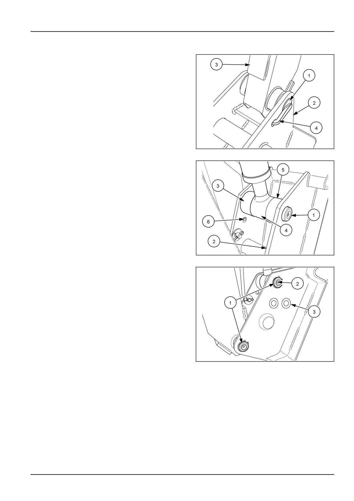
Installing the quick-attach plate
1. Start the engine of the tractor and release the parking
brake. Slowly drive the tractor toward the quick attach
plate, positioning the loader boom in the middle of the
attachment points. Stop the engine of the tractor and
set the parking brake.
2. Insert the lower pivot pins (1) outward through the
quick attach plate (2), and loader arms (3).
3. Make sure the formed pin tabs (4) are properly in-
serted into cutout hole in the quick attach plate. Re-
peat steps 2 and 3 for the other side.
86060301
1
4. Insert the upper pivot pin (1) outward through the quick
attach plate (2), thick spacer (3), cylinder rod (4), and
thin spacer (5).
5. Make sure the formed pin tabs (6) are properly in-
serted into cutout hole in the quick attach plate. Re-
peat steps 4 and 5 for the other side.
86060302
2
6. Install the retaining rings (1) on all the mounting pins
(2) securing the quick attach plate to the loader.
NOTICE: If installing an earlier production quick attach
plate (without bushings) on a newer production loader with
longer attaching pins, install two spacer washers (3) be-
tween plate ears and snap ring.
36086833
3
3-7
3 - OPERATING INSTRUCTIONS
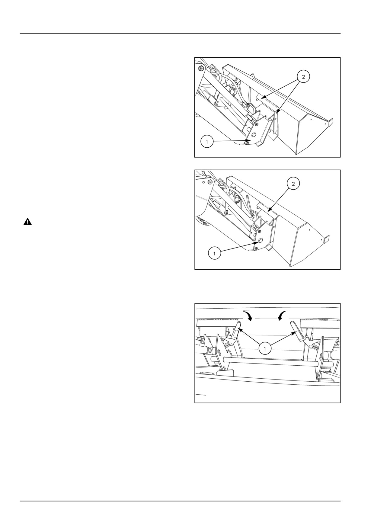
Installing the quick-attach bucket
1. Lower the loader with the quick attach plate (1) posi-
tioned below the bucket mounting plates (2) and rolled
slightly forward.
NOTICE: The area surrounding the quick attach coupler
latches and the engagement slots on the bucket must be
kept free of debris and foreign material to allow for proper
operation of the quick attach locking mechanism.
86060327
1
2. Raise the loader slightly to engage the quick attach
plate (1) into the top buckets plates (2).
3. With the quick attach plate securely engaged in the top
buckets plates, roll the bucket rearward to allow the
quick attach plate to move forward, seating the plate
on the bucket.
WARNING
Falling object hazard!
Before operating the machine, always make
sure the bucket or attachment is securely
locked into the quick-attach plate. A loader
bucket or attachment that is not securely
locked into the quick-attach plate could come
86060328
2
off during loader operation.
Failure to comply could result in death or se-
rious injury.
W0166A
4. Shut off the engine, and set the parking brake.
5. With the quick attach securely seated into the bucket,
push the left and right lock handles (1) into the locked
position.
86060329A
3
3-8

3 - OPERATING INSTRUCTIONS
6. Raise the loader and dump the bucket until the cutting
edge is resting on the ground. Visually confirm the
locking pins (1) on the quick attach plate are engaged
and locked in the bucket slots.
7. Lower the loader and roll the bucket to a level position.
56060330
4
3-9
3 - OPERATING INSTRUCTIONS
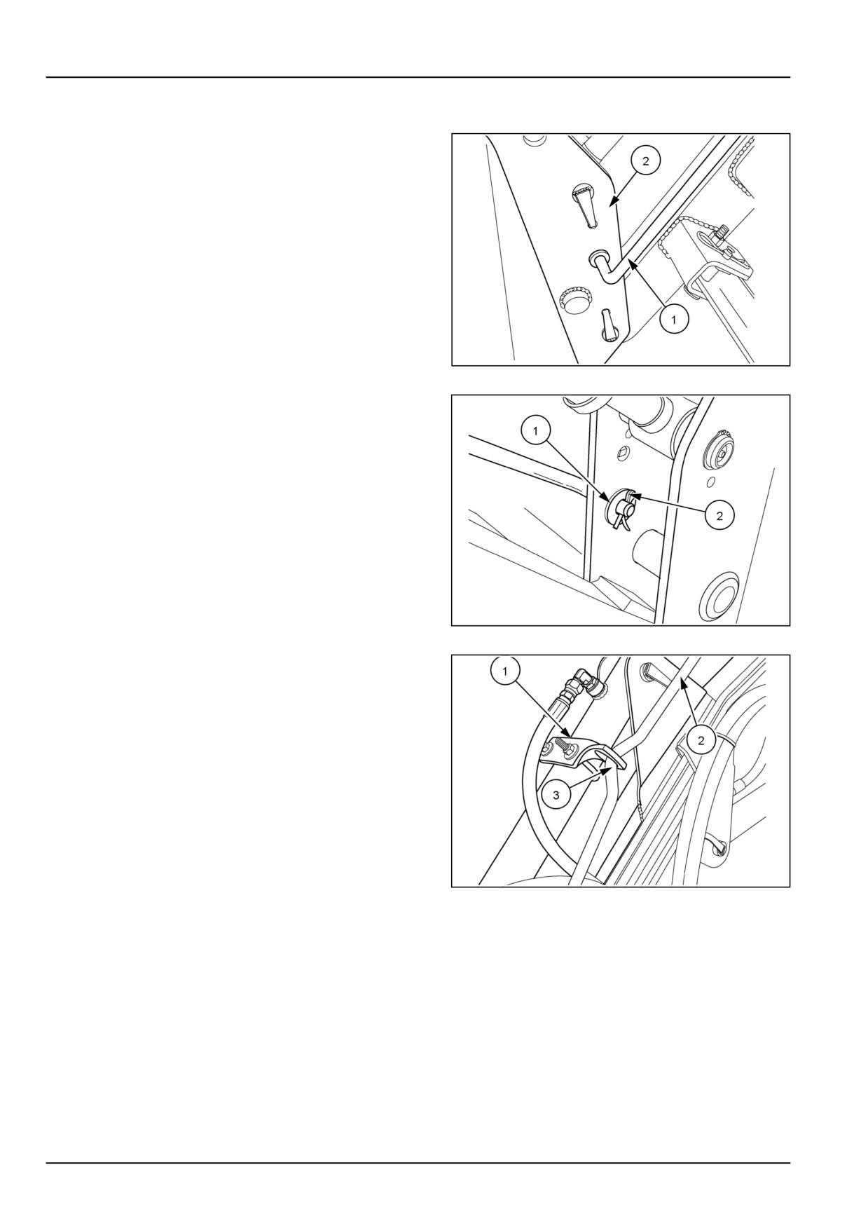
Installing the bucket level indicator
1. Install the bucket level indicator rod (1) through the
hole in the inner right side bucket plate (2).
86060304
1
2. Install the flat washer (1), and cotter pin (2) onto the
rod end.
86060305
2
3. Slide the indicator bracket (1) over the top end of the
rod (2) and position at the bend (3) in the rod.
4. Make sure that the bucket is resting on the ground,
and is in a level position.
86060306
3
3-10
3 - OPERATING INSTRUCTIONS
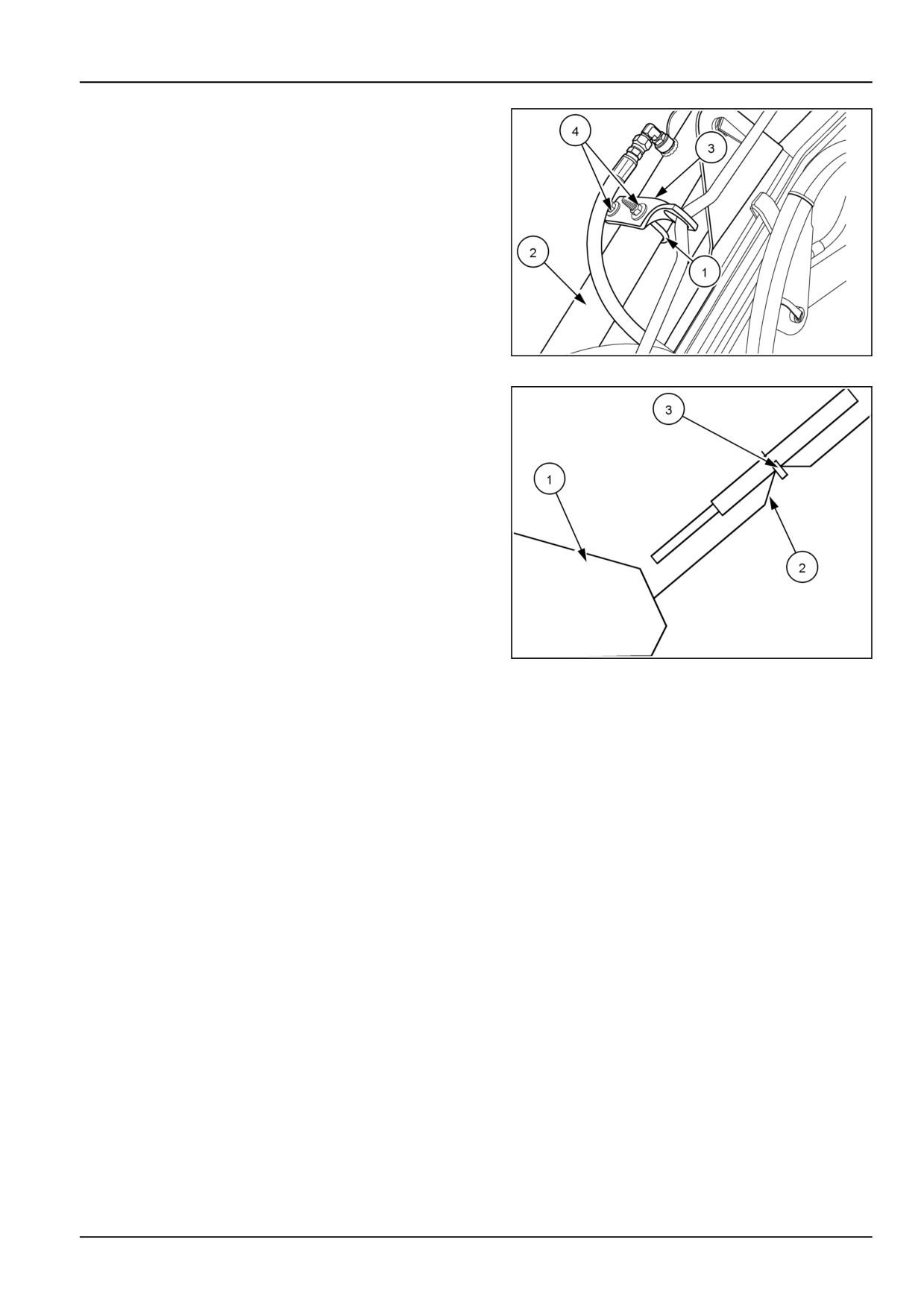
5. Install the U-bolt (1) around the bucket cylinder (2),
and through the level indicator bracket (3). Secure the
U-bolt, (1) to the level indicator bracket (3) with two
lock nuts (4).
86060306
4
6. When the bucket (1) is in the level position, the bend in
the level indicator rod (2) will be located in the indicator
bracket (3).
NOTE: If the bucket indicator does not give an accurate
level indication, the indicator bracket must be reset on the
bucket cylinder.
30998690
5
3-11
3 - OPERATING INSTRUCTIONS
PARKING THE UNIT
Removing the quick-attach bucket
WARNING
Pressurized hydraulic fluid can penetrate the skin and cause severe injuries.
Hydraulic fluid is under extreme pressure. Rest the bucket or attachment on the ground. Shut the
engine off, turn the key on, and move the hydraulic control lever through all movements several times
to relieve residual pressure in the system.
Failure to comply could result in death or serious injury.
W0161A
WARNING
Falling object hazard!
Before operating the machine, always make sure the bucket or attachment is securely locked into the
quick-attach plate. A loader bucket or attachment that is not securely locked into the quick-attach
plate could come off during loader operation.
Failure to comply could result in death or serious injury.
W0166A
NOTE: Do not place the loader control valve in the
"FLOAT" position prior to removing the quick attach
implement. Do not stand on the implement when placing
handles in the unlocked position.
1. Lower the bucket to the ground, and roll slightly rear-
ward.
2. Set the parking brake, shut off the engine.
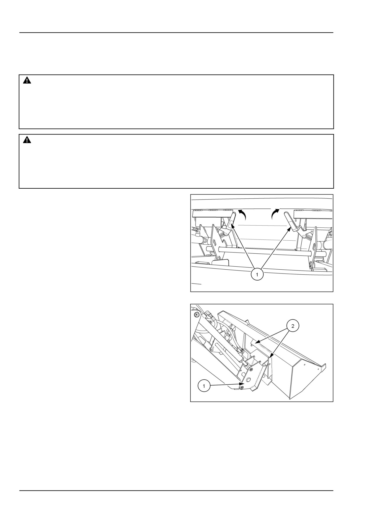
3. Lift the lock handles (1) to unlock the quick attach plate
from the bucket.
86060329B
1
4. Start the tractor engine, lower the loader while slowly
rolling the bucket forward until the quick attach plate
(1) disengages from the bucket plates (2).
5. Back the tractor away from the bucket.
86060327
2
3-12
3 - OPERATING INSTRUCTIONS
Removing the quick-attach plate
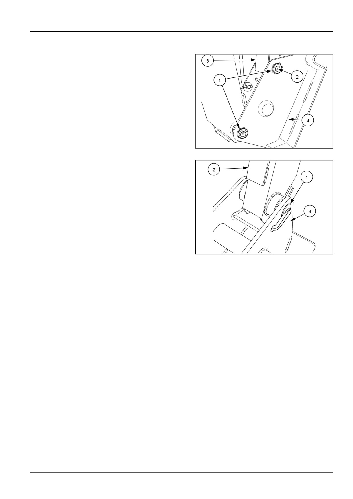
1. Remove the retaining rings (1) on all the mounting pins
securing the quick attach plate to the loader.
2. Remove the upper pivot pins (2) inward through the lift
links (3) and the quick attach plate (4).
3. Start the tractor and retract the bucket cylinders until
completely out of the way.
56064702
1
3. Remove the lower pivot pins (1) inward through the
loader arms (2), and quick attach plate (3).
4. Start the engine of the tractor and release the parking
brake. Slowly back the tractor away from the quick
attach plate (3). Stop the engine of the tractor and set
the parking brake.
86060301
2
3-13
3 - OPERATING INSTRUCTIONS
Removing the loader
WARNING
Tip-over hazard!
Always have an approved bucket mounted to the loader when the loader is removed from the tractor.
Pallet fork, bale spear, or similar attachments are too light to safely counterbalance the loader boom
arms when the loader is removed from the tractor.
Failure to comply could result in death or serious injury.
W0022B
Preparing to remove the loader from the
tractor
1. Locate the tractor and loader on firm level ground.
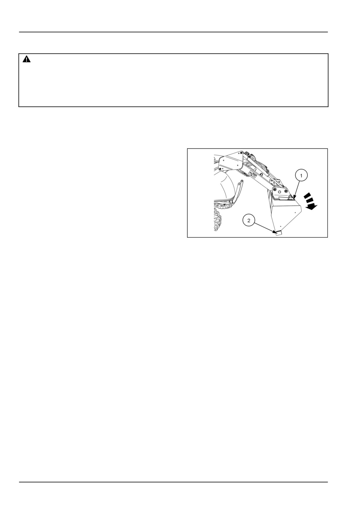
2. Lower the loader bucket (1) to the ground, cutting edge
(2) first, stop the tractor engine, and set the parking
brake.
NHIL15CT00495AA
1
3-14
3 - OPERATING INSTRUCTIONS
Deploying the park stand
WARNING
Avoid injury!
To install or remove the park stand, raise the loader and then set the loader down on its cutting edge
(the bottom surface of the bucket should be vertical).This safely supports the boom while the operator
installs or removes the park stand.
Failure to comply could result in death or serious injury.
W1248A
WARNING
Crushing hazard!
Make sure the bucket or attachment is resting on the ground before folding or unfolding loader sup-
port legs.
Failure to comply could result in death or serious injury.
W0122A
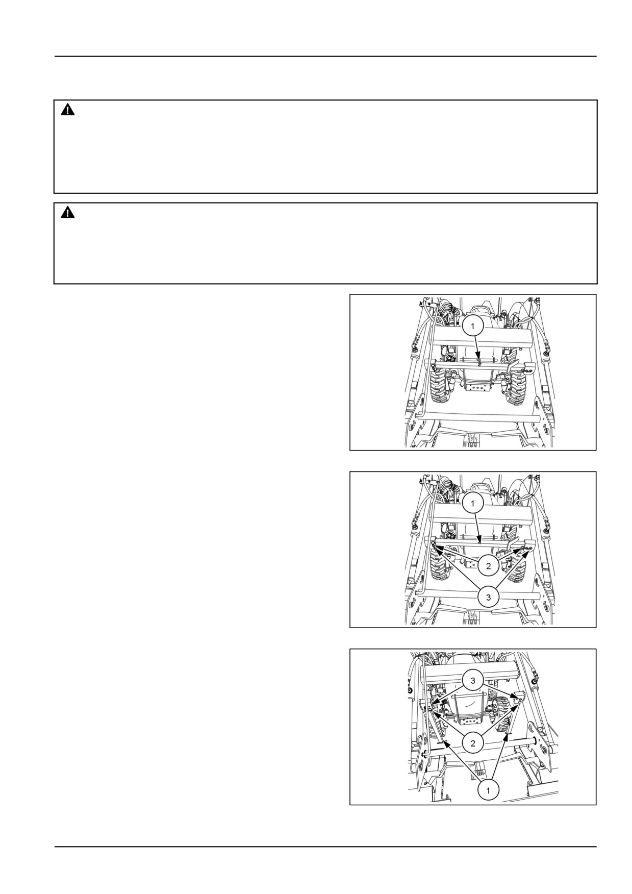
1. Remove the center stow pin safety pin (1).
NHIL15CT00497AA
2
2. Remove the park stand (1) from the stowed position
by removing the safety pins (2) and pins (3).
NHIL15CT00497AA
3
3. Unfold the park stand legs (1) and secure them with
the pins (2) and safety pins (3) in the deployed posi-
tion.
NHIL15CT00496AA
4
3-15
3 - OPERATING INSTRUCTIONS
Removing the loader from the tractor
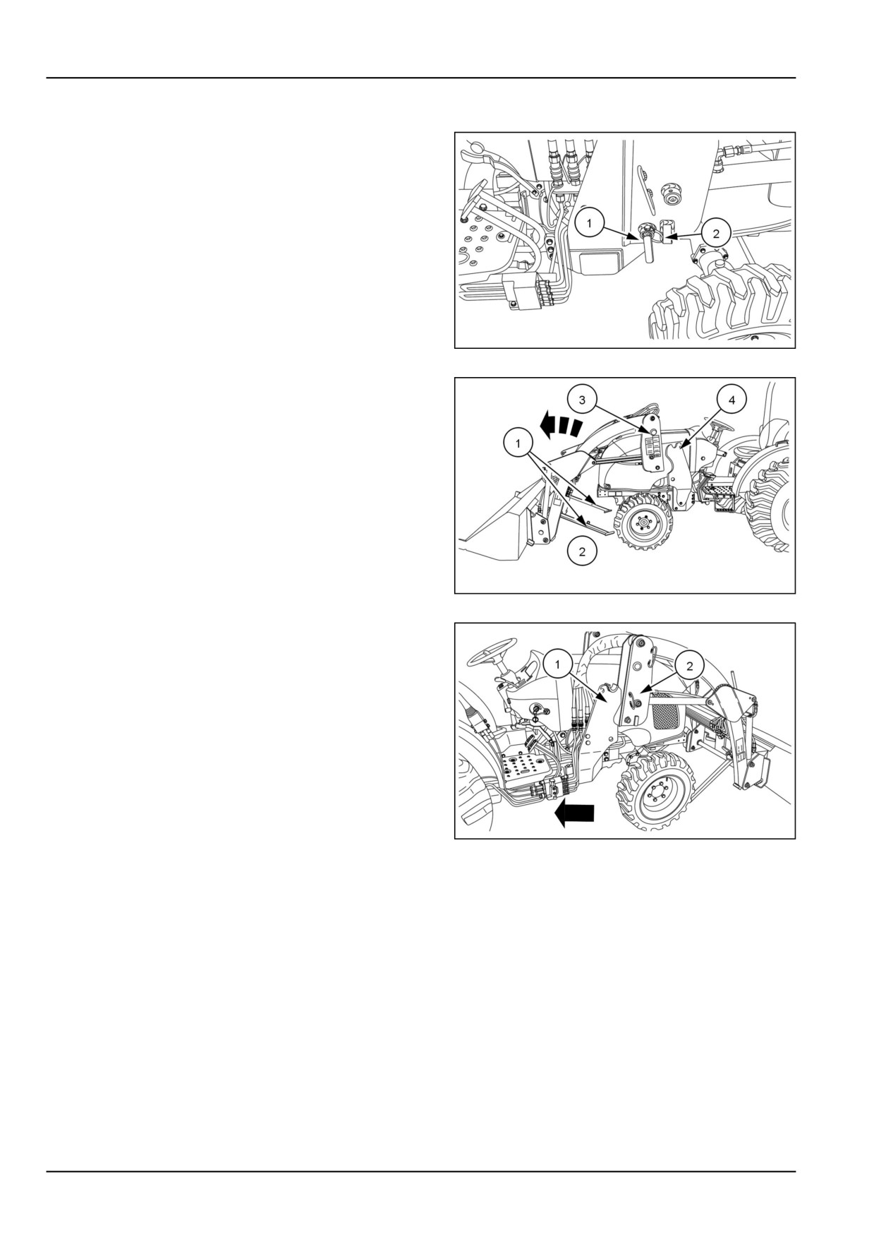
1. Remove the safety pins (1) and the frame pins (2),
from the left-hand and right-hand sides.
NHIL16CT02165AA
5
2. Start the tractor engine and release the brakes.
3. Activate the lift control lever to fully retract lift cylinders.
4. Activate the bucket control lever to retract the bucket
cylinders until the park stands (1) contact the ground
(2) and mounting bracket tubes (3) raise from the
frame channel (4).
NHIL15CT00489AA
6
5. Back the tractor up slowly, allowing the loader frame
(1) to clear the side frame channels (2).
NHIL16CT02172AA
7
NOTICE: Make sure the hydraulic hoses (1) are free as the tractor is backed away. Damage will result if the hoses
are not free.
NOTICE: Do not back away very far. Stretching the hydraulic hoses will cause damage.
3-16

3 - OPERATING INSTRUCTIONS
6. Engage the tractor brakes and stop the engine.
7. Activate the control lever to relieve the pressure in both
the bucket and lift circuits.
8. Disconnect the quick couplers and install clean dust
covers (1) and plugs (2) on all couplers. Position the
loader hoses (3) on the loader so they do not contact
the ground.
NHIL16CT01065AA
8
3-17
4 - WORKING OPERATIONS
4 - WORKING OPERATIONS###_6_###
GENERAL INFORMATION
Operating the loader
WARNING
Avoid injury!
Excessive speed is dangerous and may cause spillage and excessive strain on the bucket.
Failure to comply could result in death or serious injury.
W1306A
The loader should be operated with the tractor engine run-
ning at 1700 - 2200 RPM.
When operating in temperatures below -17 °C (0 °F), run
the tractor engine below 1500 RPM and do not operate
the loader for approximately 10 to 15 minutes to allow the
hydraulic oil to increase in temperature.
The following text and illustrations present suggested
loader and tractor operating techniques.
Handling large heavy objects
WARNING
Handling large heavy objects can be extremely dangerous!
Using front end loaders for handling large round or rectangular bales, logs, and oil drums is not rec-
ommended. If you must perform the above type of work, protect yourself by following all instructions
below and in the SAFETY INFORMATION section.
Failure to comply could result in death or serious injury.
W0027A
When handling large heavy objects, ALWAYS do the fol-
lowing:
• Use the proper attachment.
• Never lift the load higher than necessary to clear the
ground when moving.
• Ballast the tractor rear to compensate for the load.
• Never lift large objects with equipment that does not
have an anti-rollback device.
• Move slowly and carefully, and avoid rough terrain.
4-1
4 - WORKING OPERATIONS
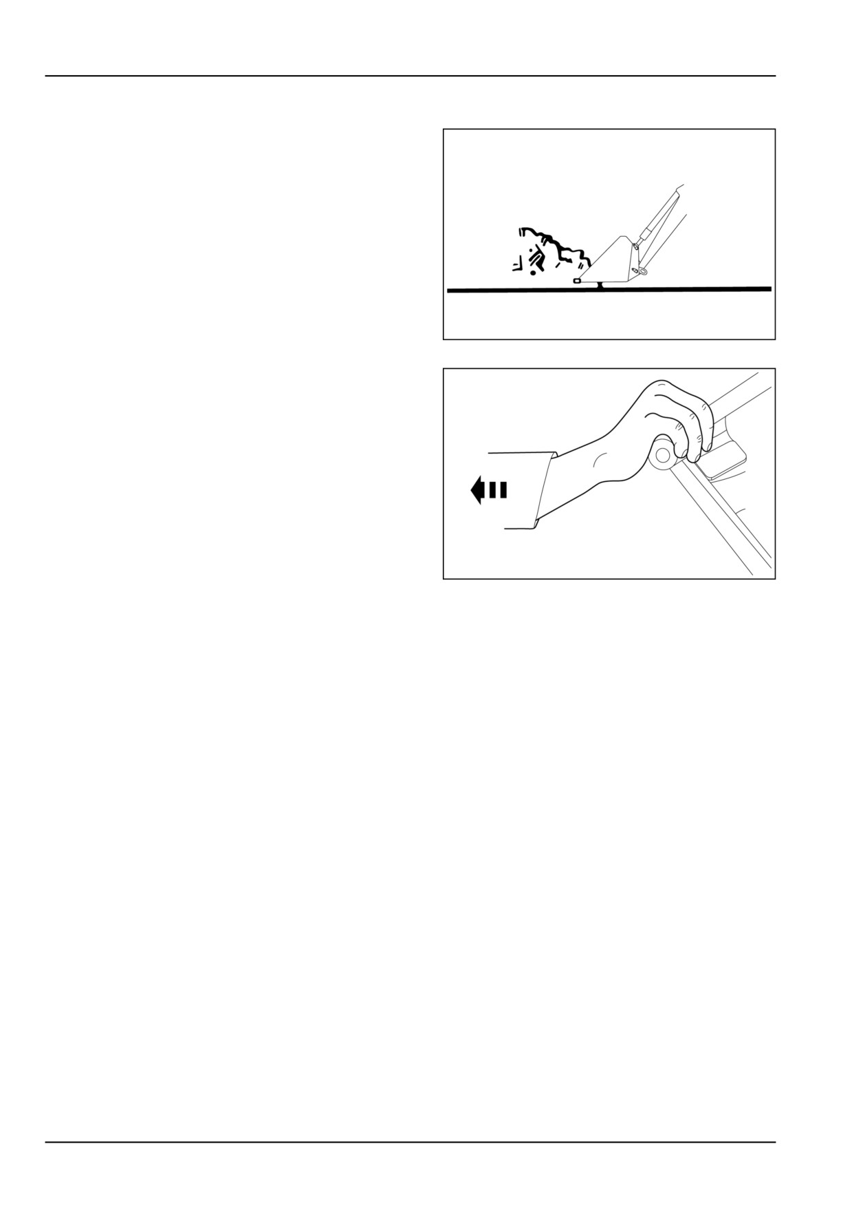
Filling the bucket
Approach and enter the pile with a level bucket.
NHIL13CT00861AA
1
Ease the single lever control back to lift the bucket and to
the left to roll back the bucket.
NHIL13CT00862AA
2
4-2
4 - WORKING OPERATIONS
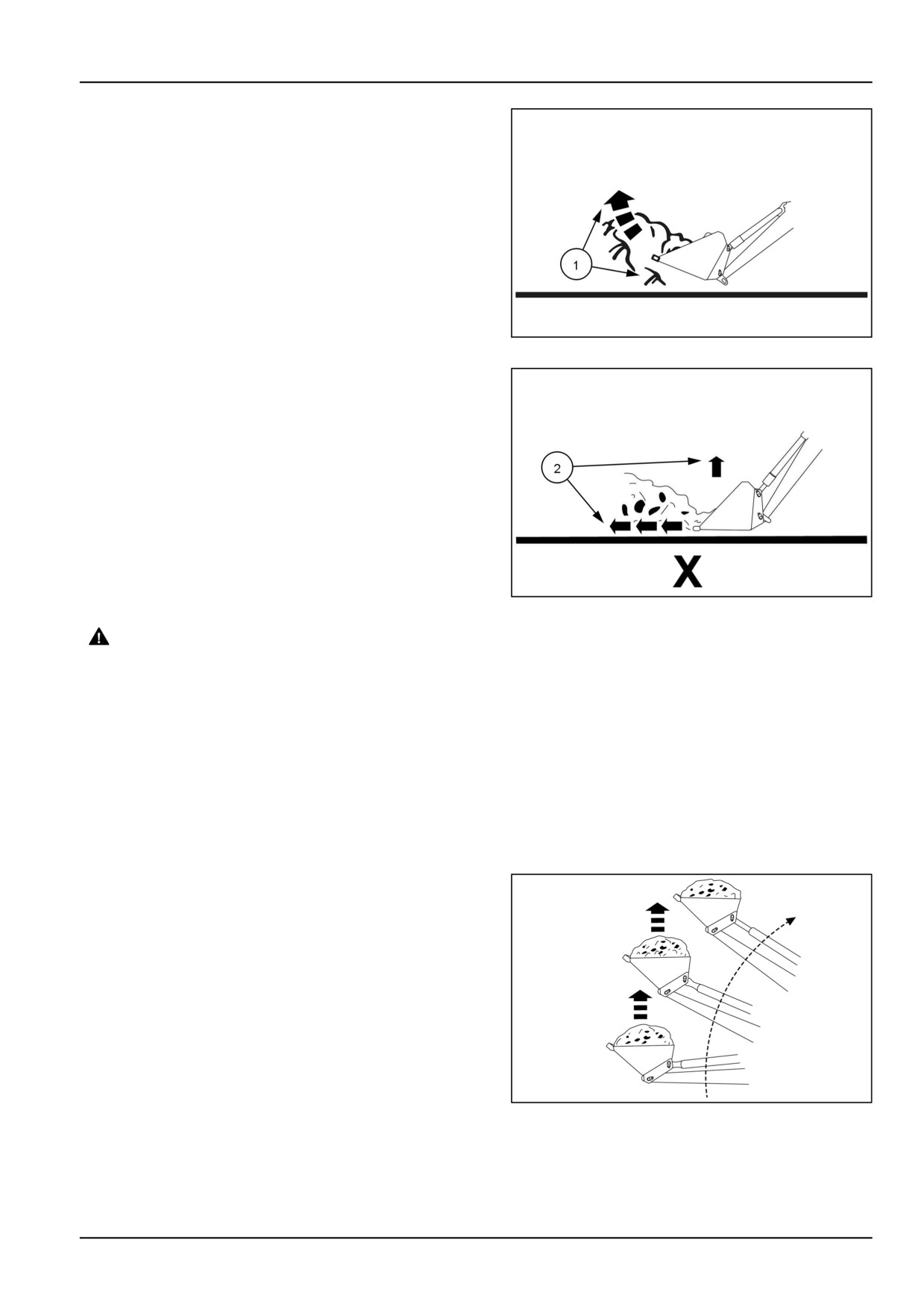
The lift and rollback of the bucket increases efficiency.
(1) Do this.
NHIL13CT00863AA
3
This is because a level bucket throughout the lifting cycle
resists bucket lift and increases breakaway effort.
(2) Not This
NHIL13CT00864AA
4
WARNING
Roll-over hazard! A full bucket in the raised
position alters the center of gravity of the ma-
chine.
When operating a loader with a full bucket on
slopes, observe the following precautions:
1. Avoid turning the machine on slopes.
2. Always drive slowly straight up and down
slopes.
3. Always carry the load as low as possible.
Failure to comply could result in death or se-
rious injury.
W0018A
NOTE: Do not be concerned if the bucket is not com-
pletely filled during each pass. Maximum productivity is
determined by the amount of material loaded in a given
period of time, and time is lost if two or more attempts are
made to fill the bucket on each pass.
Lifting the load
Keep the bucket positioned to avoid spillage when lifting
the load.
NOTICE: Do not attempt to lift bucket loads in excess of
loader capacity.
NHIL13CT00865AA
5
4-3
4 - WORKING OPERATIONS
Carrying the load
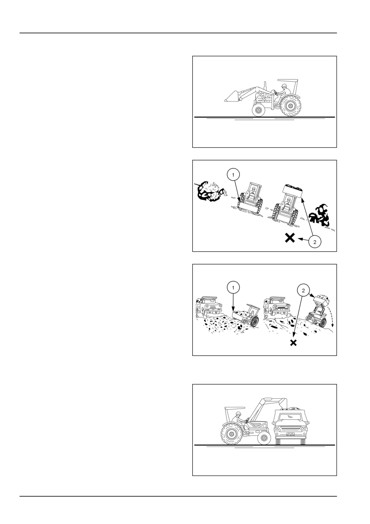
Position the bucket just below the level of the tractor hood.
This provides for maximum stability and visibility, whether
the bucket is loaded or empty.
NHIL13CT00866AA
6
Carry the bucket as low as possible when operating the
loader on a slope. This keeps the bucket and tractor cen-
ter of gravity low, providing maximum tractor stability.
(1) Do this.
(2) Not this.
NHIL13CT00867AA
7
When transporting the load, keep the bucket as low as
possible. This helps to avoid tipping in the event a wheel
drops into a rut.
(1) Do this.
(2) Not this.
NHIL13CT00868AA
8
Dumping the bucket
Lift the bucket high enough to clear the vehicle's side.
Move the tractor in as close as possible to the side of the
vehicle, and then dump the bucket.
Lowering the bucket
After the bucket is dumped, back away from the vehicle
while lowering and rolling back the bucket.
NHIL13CT00869AA
9
4-4
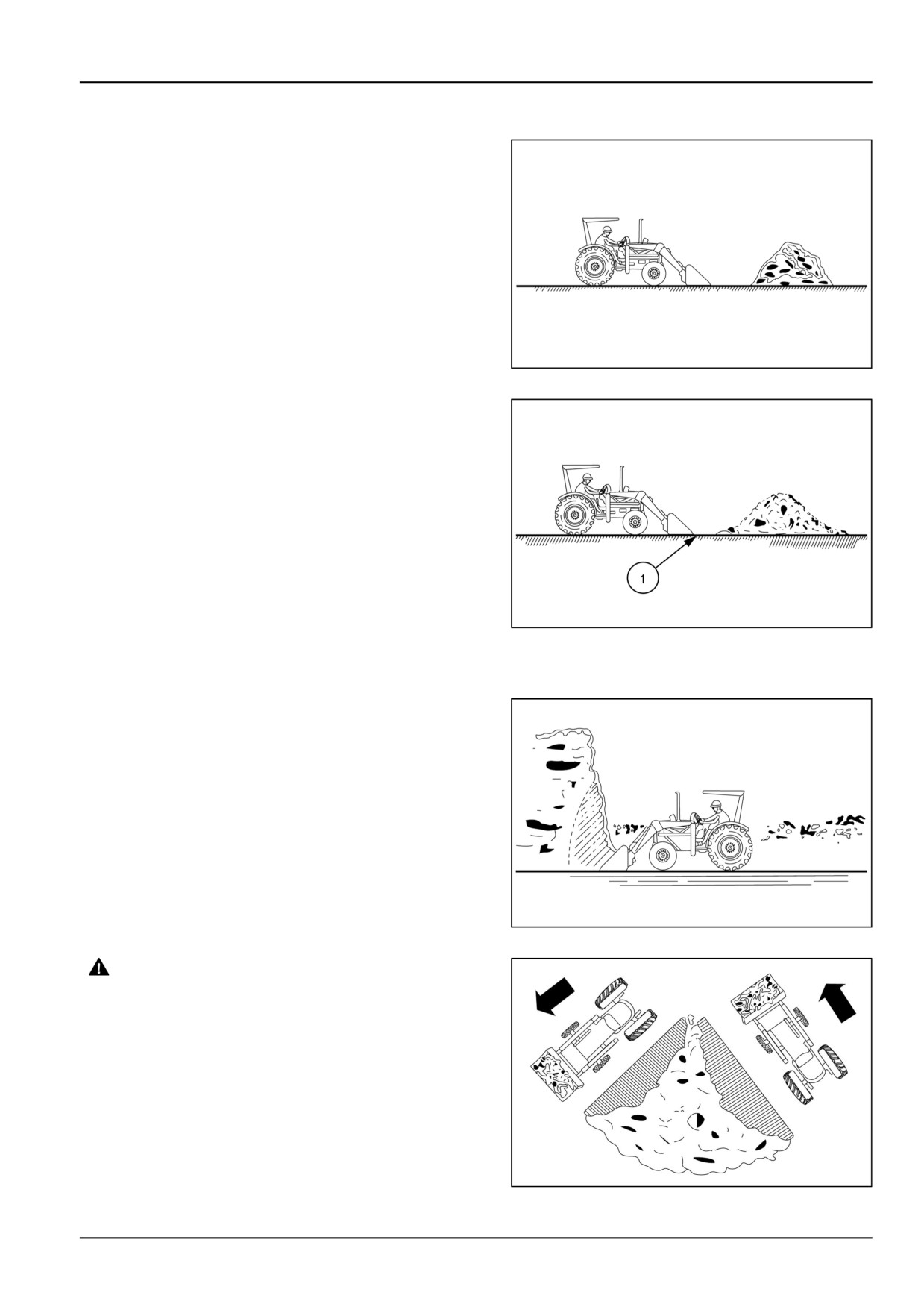
4 - WORKING OPERATIONS
Operating with float control
The bucket will wear faster if hydraulic down pressure is
exerted during loader operation. To prevent this from oc-
curring, keep the bucket level and put the lift control in the
float position during hard surface operation, allowing the
bucket to float on the working surface.
NHIL13CT00870AA
10
Utilizing the float position also helps prevent the mixing of
surface material with stockpile material. This is because
the float position reduces the chance of surface gouging
when removing snow or other material, or when working
with a blade.
(1) Surface material.
NHIL13CT00871AA
11
Loading from a bank
Choose a forward gear that provides sufficient ground
speed for loading.
Load from the lowest position possible for maximum ef-
ficiency. Loader lift and breakaway capacity diminish as
loading height is increased.
NHIL13CT00872AA
12
WARNING
Falling objects!
Dirt slides can be dangerous. Exercise ex-
treme care when undercutting high banks.
Watch for falling rocks and cave-ins.
Failure to comply could result in death or se-
rious injury.
W0021A
Side-cutting is a good technique for cutting down a large
pile of material.
NHIL13CT00873AA
13
4-5
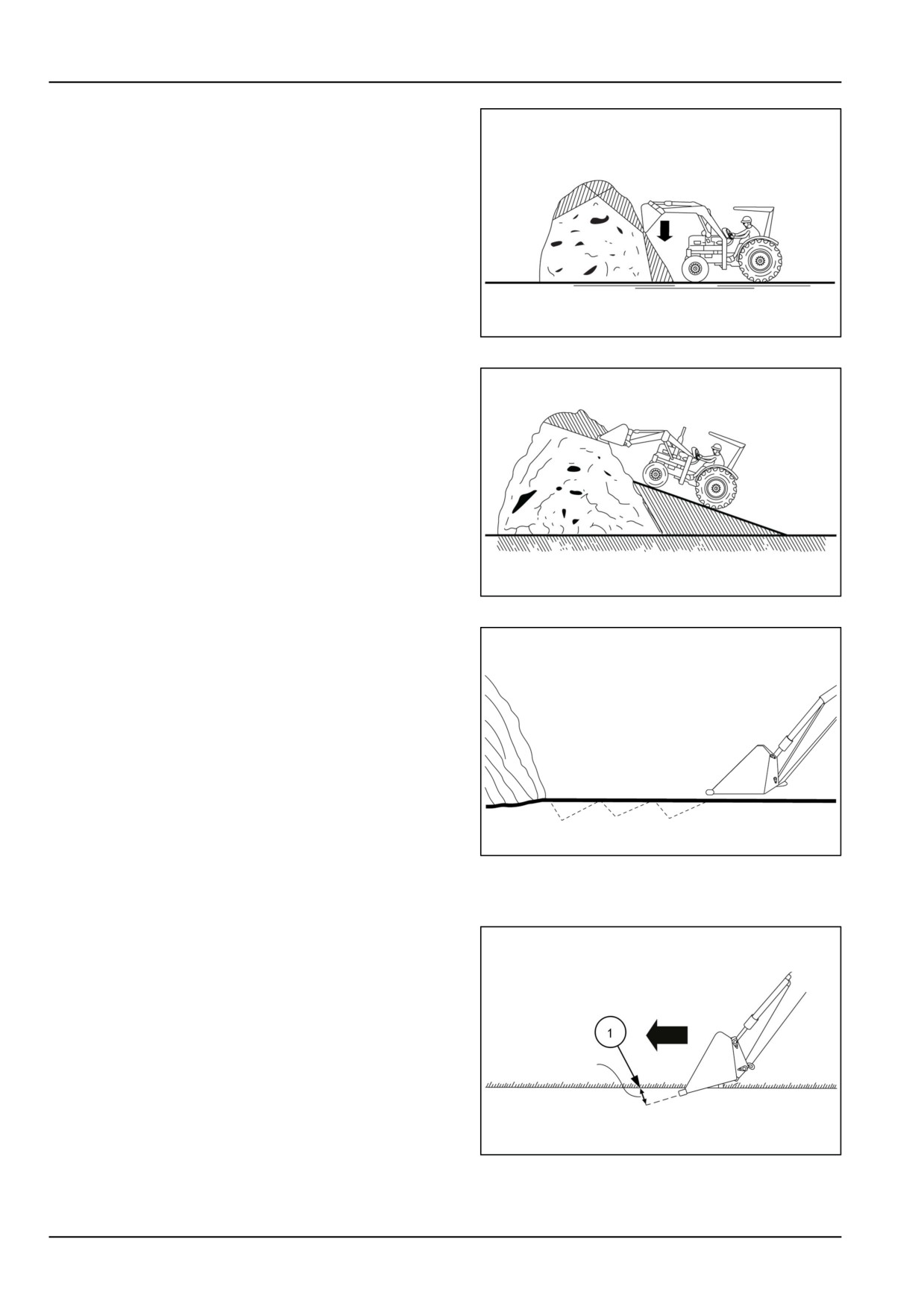
4 - WORKING OPERATIONS
If the pile sides are too high and likely to cause cave-in,
use the loader to break down the sides until a slot can be
cut over the top.
NHIL13CT00874AA
14
Another effective method of loading from large dirt piles is
to build a ramp approach
NHIL13CT00875AA
15
NOTE: Keep the bucket level when approaching a bank
or pile to help prevent gouging the work area.
NHIL13CT00876AA
16
Peeling and scraping
Use a slight bucket angle, travel forward, and hold the lift
control forward to start the cut. Make a short angle cut 1.5
- 2.4 m (5 - 8 ft) and break out cleanly.
(1) 152 mm (6.0 in).
NHIL13CT00877AA
17
4-6
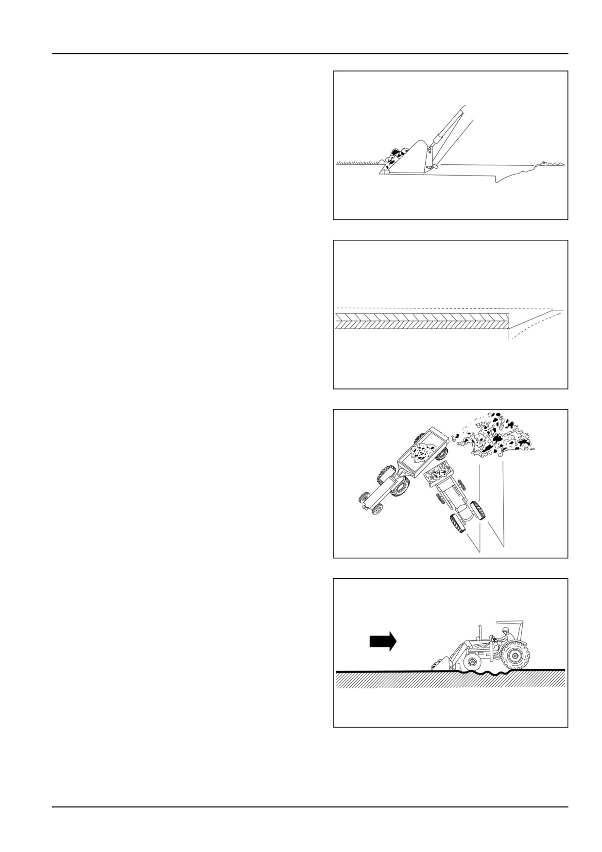
4 - WORKING OPERATIONS
With the bucket level, start a cut at the notch approxi-
mately 51 mm (2 in) deep. Hold the depth by feather-
ing the bucket control to adjust the cutting lip up or down.
When the front tires enter the notch, adjust the lift cylinder
to maintain proper depth.
NHIL13CT00878AA
18
Make additional passes until the desired depth is reached.
During each pass, use the bucket control only while at
working depth. This allows you to concentrate on control-
ling the bucket angle and maintaining a precise cut.
NHIL13CT00879AA
19
Loading low trucks or spreaders from a pile
Minimize the angle of turn and length of run between the
pile and spreader for faster loading.
NHIL13CT00880AA
20
Back-grade occasionally with a loaded bucket to keep the
working surface free of ruts and holes. Hold the lift control
forward so the full weight of the bucket is scraping the
surface and use the heel of the bucket.
NHIL13CT00881AA
21
4-7
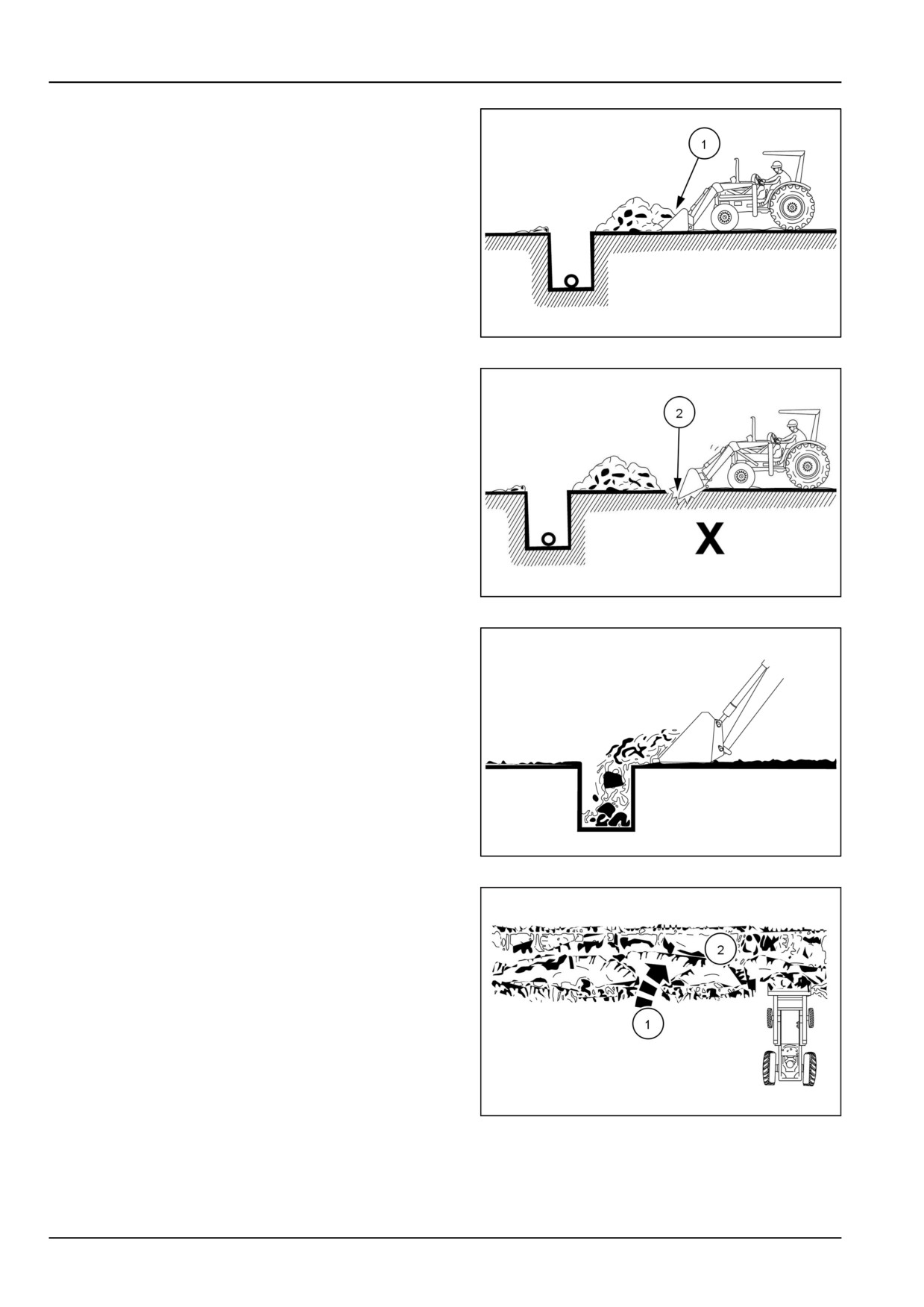
4 - WORKING OPERATIONS
Backfilling
Approach the pile with a flat bucket. Poor methods move
no more dirt and make it more difficult to hold a level
grade.
(1) Do this
NHIL13CT00882AA
22
When bulldozing, do not use the bucket in the dumped
position. This method forces severe shock loadings on
the dump linkage, the bucket cylinder, and the tractor.
(2) Not this
NHIL13CT00883AA
23
Leave dirt in the bucket. Dumping on each pass wastes
time.
NHIL13CT00884AA
24
Operate at right angles to the ditch and take as large of a
bite as the tractor can handle without lugging down.
(1) Soil pile
(2) Ditch
NHIL13CT00885AA
25
4-8
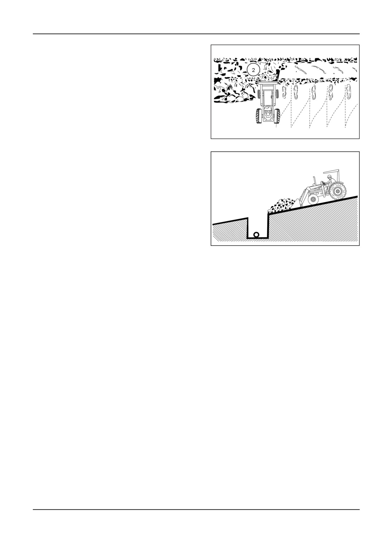
4 - WORKING OPERATIONS
Leave any dirt which drifts over the side of the bucket for
final cleanup.
(2) Ditch
NHIL13CT00886AA
26
Pile dirt on the high side for easier backfilling on a slope.
NHIL13CT00887AA
27
4-9
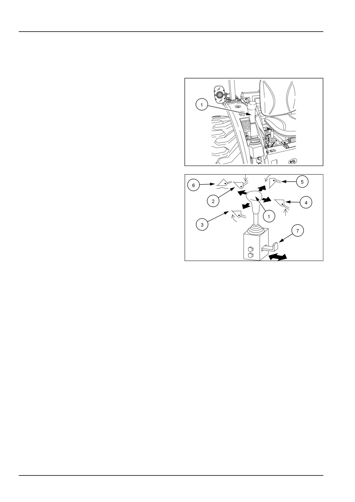
4 - WORKING OPERATIONS
Front remote control valve
Front Remote Control Valve Workmaster™
35 or 40
The front remote control valve (1) is mounted to the front of
the right-hand fender. This valve is used mainly for front
end loader operation, but may also be used to operate
other front mounted implements.
To operate the two-spool valve, move the control lever (1)
in any of the four directions.
Release the control lever to stop the cylinder in any posi-
tion, the lever automatically returns to neutral.
• Move the control lever forward to lower the loader/re-
tract cylinder (2).
• Move the control lever to the left to curl the bucket/re-
tract cylinder (3).
NHIL15CT00449AA
1
• Move the control lever rearward to raise the loader/ex-
tend cylinder (4).
• Move the control lever to the right to dump bucket/ex-
tend cylinder (5).
• Move the control lever fully forward to "FLOAT" the
bucket (6) which allows a cylinder to extend or retract
freely.
NOTE: Do not use the "FLOAT" position if the loader is
raised to its highest position.
NOTE: Push the locking lever (7) in when the two-spool
control valve is not used.
93100858
2
NOTE: If you move the control lever diagonally the loader
and bucket will operate at the same time.
4-10
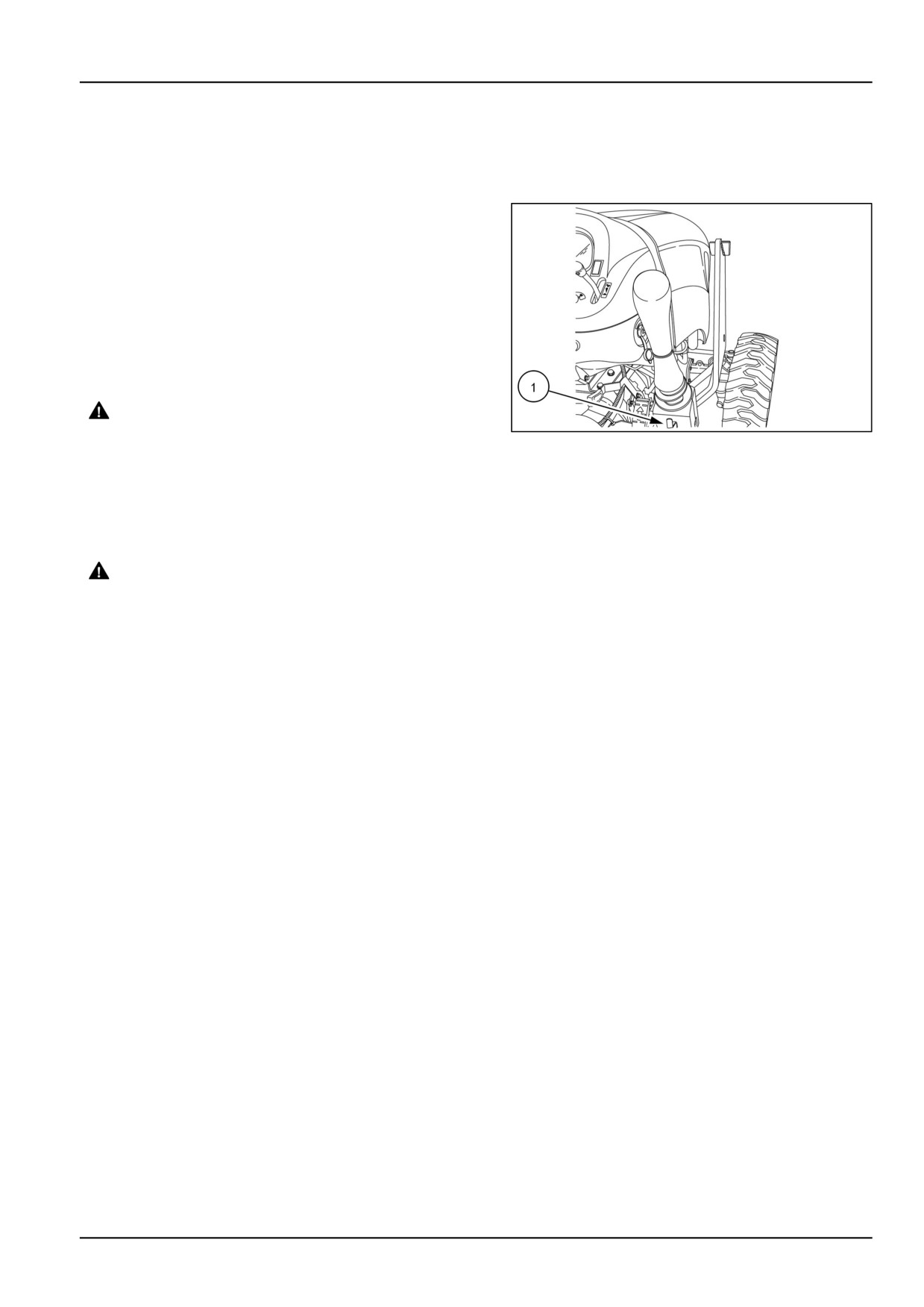
4 - WORKING OPERATIONS
Front remote control valve - lock out
Front Remote Control Valve Workmaster™
35 or 40
The two spool valve is equipped with a valve lock feature.
The valve lock, mechanically locks the boom and bucket
spool linkages in the neutral position. To operate lock, pull
the lever (1) outward to release valve lock. To engage
lock, push the lever inward.
The valve lock is recommended to be used to prevent ac-
cidental activation of the boom and bucket spools during
operation of the tractor. The lock is not intended and will
not prevent leak down of loader boom during periods of
storage.
WARNING
Crushing hazard!
NHIL15CT00482AA
1
Before disconnecting the cylinders or equip-
ment, make sure you adequately support and
secure the equipment or implement.
Failure to comply could result in death or se-
rious injury.
W0243A
WARNING
Escaping fluid!
Remote couplers must be properly mounted
and securely fastened to the machine mount-
ing bracket for proper functioning of the safety
disconnect feature.
Failure to comply could result in death or se-
rious injury.
W0131A
4-11
4 - WORKING OPERATIONS
4-12
5 - MAINTENANCE
5 - MAINTENANCE###_7_###
GENERAL INFORMATION
Basic instructions
CAUTION
Unexpected machine movement!
1. Disengage all drives.
2. Engage parking brake.
3. Lower all attachments to the ground, or raise and engage all safety locks.
4. Shut off engine.
5. Remove key from key switch.
6. Switch off battery key, if installed.
7. Wait for all machine movement to stop.
Failure to comply could result in minor or moderate injury.
C0038A
Adequate lubrication and maintenance on a regular schedule is vital to maintaining your equipment. To ensure long
service and efficient operation, follow the lubrication and maintenance schedules outlined in this manual. The use of
proper fuels, oils, grease and filters, as well as keeping the systems clean, will also extend machine and component
life.
NOTICE: Always use genuine NEW HOLLAND replacement parts, oils and filters to ensure proper operation, filtration
of engine and hydraulic systems. See your NEW HOLLAND dealer for additional oil quantities.
General Information
NOTICE: While any company can perform necessary
specifications. Improperly or incorrectly performed main-
maintenance or repairs on your equipment, NEW HOL-
tenance and repair voids the equipment warranty and
LAND strongly recommends that you use only authorized
may affect service intervals.
NEW HOLLAND dealers and products that meet given
Regular lubrication is the best insurance against delays and repairs. Proper lubrication will extend machine life. Refer
to the following charts for lubricants and service intervals.
NOTICE: Failure to complete the required maintenance at the recommended intervals can cause unnecessary down-
time.
The intervals listed are guidelines to be used when operating in normal conditions. Adjust the intervals for operating
in adverse environmental and working conditions. The intervals must be shortened for sandy, dusty and extremely
hot operating conditions.
Check all hardware to ensure that it has been properly installed and tightened. Retighten the hardware after the first
10 hours of operation and every 50 hours thereafter.
Grease Fittings
Wipe dirt from fittings before greasing. Pump fresh grease into fitting to adequately lubricate the component and force
out any contamination from the grease passage. Wipe off excess grease. Use a grease gun containing clean, high
grade multipurpose grease.
5-1
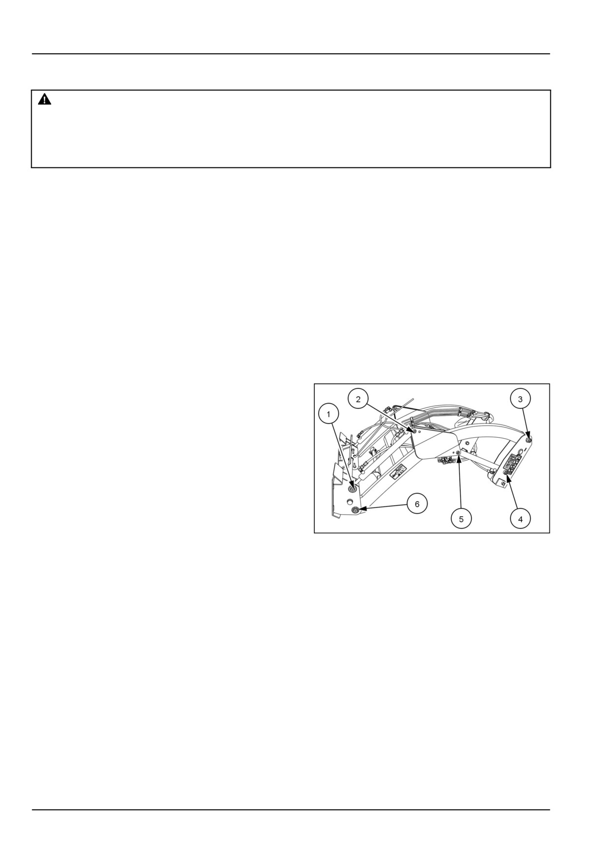
5 - MAINTENANCE
Daily inspection
WARNING
Crushing hazard!
Before attempting any maintenance on the loader or tractor, always make sure the loader is in the
down position and the bucket or attachment is resting on the ground.
Failure to comply could result in death or serious injury.
W0119A
Optimum machine performance and long life can only be
and replacement of worn or damaged parts. A thorough
achieved through a comprehensive owner maintenance
program reduces maintenance costs and eliminates un-
program. Such a program includes regular lubrication
necessary downtime.
NOTICE: The hour intervals between servicing, as listed in this section, are guidelines and should be considered the
maximum service intervals for normal use and working conditions. Reduce these intervals accordingly when operating
under extreme conditions.
Daily Maintenance
When using the tractor's hydraulic system to operate the loader, check the level of hydraulic oil in the tractor before
the start of each day's operation. If necessary, add HYDRAULIC TRANSMISSION OIL - PREMIUM.
Lubricate the 12 grease fittings after every 8 hours of operation. As illustrated below; these fittings are found at the
rear of each lift arm, for bucket pivot, as well as at the rod and barrel end of each cylinder.
Grease Locations
The 12 grease points are shown below. They are found
on both sides of the loader in the identified locations.
NHIL15CT00484AA
1
5-2
5 - MAINTENANCE
WARNING
Pressurized hydraulic fluid can penetrate the skin and cause severe injuries.
Tighten all of the connections before starting the engine. If hydraulic fluid has penetrated the skin,
seek medical assistance immediately.
Failure to comply could result in death or serious injury.
W0117A
WARNING
Crushing hazard!
The loader must be attached to the tractor with the bucket or attachment resting on the ground when
repairing or replacing any loader parts.
Failure to comply could result in death or serious injury.
W0121A
Repair hydraulic leaks promptly to avoid loss of oil and serious personal injury from escaping oil.
Replace hoses immediately if they are severely damaged by a cut or scrape, extruded at the fittings, or leaking.
Check all loader mount hardware after 10 hours of operation and every 50 hours of operation thereafter.
Checking Loader Operation
1. Start the tractor engine and run at idle speed. Move the single lever loader control slowly to check for proper
loader action. If any control does not function as displayed on the decal, lower the loader, stop the engine, and
switch lines for that function to attain proper operation.
2. Color-coded plastic caps are provided to identify the hose connections for future hookups. Place the same color
caps on the male and female couplers for proper identification and machine operation.
3. After all plumbing is completed, start the tractor engine and slowly cycle the lift and bucket cylinders several times
to free the system of air. Next, retract the cylinders and stop the engine. Add additional HYDRAULIC TRANSMISSION
OIL - PREMIUM hydraulic oil to bring the oil level up to the full mark, as specified in your tractor owner's manual.
NOTE: During cold weather operation, tractor hydraulic oil can be changed to MULTI-SEASON HYDRAULIC
TRANSMISSION OIL SAE 0W-20 . The F200 oil is a multi-viscosity oil which has improved flow characteristics in low
temperatures and can be used year round.
5-3
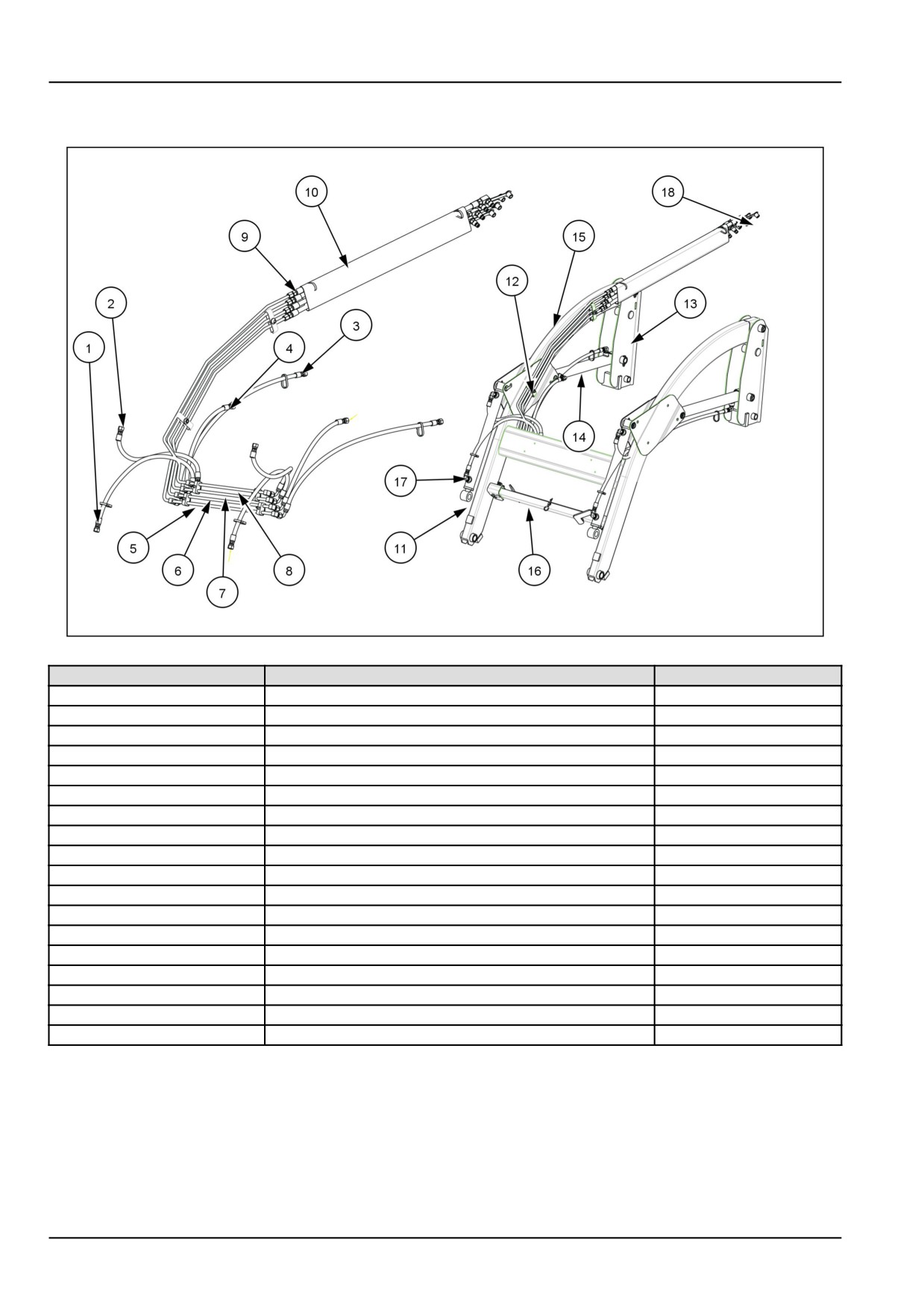
5 - MAINTENANCE
Hydraulics
NHIL15CT00500FA
1
Ref.
Description
Qty.
(1)
Bucket cylinder rod end hose
2
(2)
Bucket cylinder base end hose
2
(3)
Lift cylinder rod end hose
2
(4)
Lift cylinder base end hose
2
(5)
Hydraulic tube lift cylinder rod end
1
(6)
Hydraulic tube lift cylinder base end
1
(7)
Hydraulic tube bucket cylinder base end
1
(8)
Hydraulic tube bucket cylinder rod end
1
(9)
Hydraulic hose 3/8" ID, 2032 mm (80 in) Length
4
(10)
Protective sleeve
1
(11)
Bucket cylinder assembly
2
(12)
Tube clamp
2
(13)
Loader rear upright
2
(14)
Lift cylinder assembly
2
(15)
Boom assembly
1
(16)
Parking stand assembly
2
(17)
Fitting 90° O-ring - 37° Flare
4
(18)
Dust caps
4
5-4

5 - MAINTENANCE
Recommended Lubricants
Lubricant
Type and Description
Part Number
Container Size
Transmission/Hydraulic Oil
HYDRAULIC TRANSMISSION
9624655DS
0.946 l (1 US qt)
OIL - PREMIUM
9624656DS
3.785 l (1 US gal)
9624450
9.46 l (2.5 US gal)
9624451
18.93 l (5 US gal)
MULTI-SEASON HYDRAULIC
86523625DS
3.785 l (1 US gal)
TRANSMISSION OIL SAE
86523626DS
18.93 l (5 US gal)
0W-20
86523627DS
208.2 l (55 US gal)
Grease
MULTI-PURPOSE GREASE
9613310
Tube - 14 oz.
EXTREME PRESSURE AND
ANTI-WEAR NLGI 2
5-5
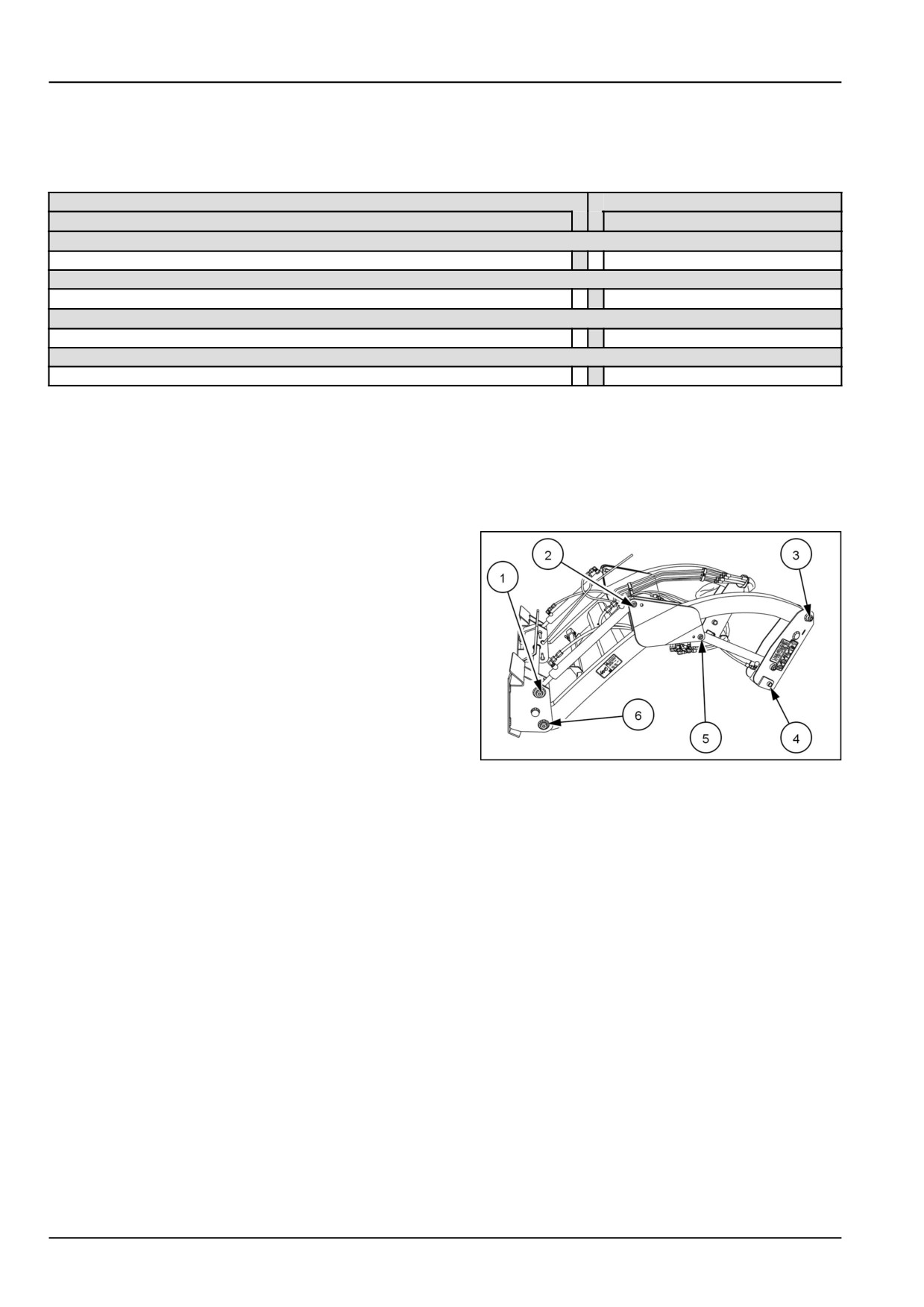
5 - MAINTENANCE
MAINTENANCE CHART
Maintenance planning
Lubricate
Check
Maintenance action
Page no.
Every 8 hours or daily
Front loader and bucket - Lubricate
x
5-6
DAILY
Tractor hydraulic oil reservoir - Check
x
5-6
After the first 10 hours of operation
Hardware - Check
x
5-6
50 hours
Hardware - Check
x
5-7
Every 8 hours or daily
Front loader and bucket - Lubricate
Grease Locations
Lubricate the 12 grease fittings after every 8 hours of
operation. As illustrated below; these fittings are found
at the rear of each lift arm, for bucket pivot, as well as
at the rod and barrel end of each cylinder.
The 12 grease points are shown below. They are found
on both sides of the loader in the identified locations.
NHIL15CT00484AA
1
DAILY
Tractor hydraulic oil reservoir - Check
Daily Maintenance
When using the tractor's hydraulic system to operate
the loader, check the level of hydraulic oil in the tractor
before the start of each day's operation. If necessary,
add HYDRAULIC TRANSMISSION OIL - PREMIUM.
After the first 10 hours of operation
Hardware - Check
Check all loader mount hardware after 10 hours of op-
eration and every 50 hours of operation thereafter.
5-6
5 - MAINTENANCE
50 hours
Hardware - Check
Check all loader mount hardware after 10 hours of op-
eration and every 50 hours of operation thereafter.
5-7

6 - TROUBLESHOOTING
6 - TROUBLESHOOTING###_8_###
SYMPTOM(S)
Front loader and bucket - Troubleshooting
Problem
Possible Cause
Correction
Loader is slow or will not
Hydraulic oil too heavy.
Change to proper oil ( or for cold weather
lift and/or dump.
operation).
Tractor hydraulic filter plugged.
Replace filter.
Tractor hydraulic pump worn.
Repair or replace pump.
Oil line restricted or leaking.
Check all hoses and tubes for leaks, dam-
age, or restrictions. Replace damaged or
restricted hoses or tube lines.
Faulty hydraulic quick couplers.
Check hose couplers for leaks, damage, or
restrictions.
Control valve does not shift properly.
Inspect, clean, repair, or replace control
valve.
Air in hydraulic system.
Cycle lift cylinders and bucket cylinders
several times to free system of air.
Tractor diverter valve in wrong position.
Turn diverter valve.
Cylinder leaks.
Replace seals.
Hydraulic plumbing incorrect.
Recheck plumbing.
Faulty tractor hydraulic relief valve.
Clean or replace relief valve.
Loader chatters or
Mechanical binding of pivot areas.
Clean pivot pins.
Grease as recom-
vibrates when raising
mended.
or lowering.
Air leak in inlet line.
Check, tighten, or replace inlet line.
Air in hydraulic system.
Cycle lift cylinders and bucket cylinders.
Oil level too low.
Add oil as required ( or for cold weather
operation).
Pump is noisy
Inlet line restricted or leaking
Check for air leaks, restrictions, or a col-
lapsed hose. Tighten or replace hose.
Change filter if necessary.
Oil level too low.
Add oil as required.
Pump worn or damaged.
Repair or replace pump.
Bucket tines bend or
Only a few tines were under the load.
Be sure three or more tines are under the
break
load.
Excessive wear on bucket
Bucket is riding on cutting edge instead of
Use boom "FLOAT" position or bucket level
cutting edge.
wear pads.
indicator to ensure bucket rides on wear
pads.
6-1

7 - SPECIFICATIONS
7 - SPECIFICATIONS###_9_###
Loader specifications
140TL
Tractor Model
Workmaster™ Hydro-Static Transmission (HST) or
mechanical transmission
Bucket
68 in. HD Mat'l
Tires
25X8.50-14 6PR (R4) front
43x16.00-20 4PR (R4) rear
Rated flow
31 L/min (8 US gpm)
Rated pressure
16671 kPa (2418 psi)
Rated engine speed
2600 RPM
(A) Maximum lift height (to bucket pivot pin)
2337 mm (92 in)
(B) Maximum lift height (under level bucket)
2134 mm (84 in)
(C) Clearance with bucket dumped
1626 mm (64 in)
(D) Reach at maximum lift height
1067 mm (42 in)
(E) Maximum dump angle
48°
(F) Reach with bucket on ground
1930 mm (76 in)
(G) Maximum roll back angle
28°
(H) Digging depth
127 mm (5 in)
Lift capacity (bucket pivot pin, max height)
571 kg (1259 lb)
Lift capacity (500 mm forward, max height)
400 kg (881 lb)
Lift capacity (bucket pivot pin, 1500 mm height)
729 kg (1607 lb)
Lift capacity (500 mm forward, 1500 mm height)
540 kg (1191 lb)
Breakout force (bucket pivot pin)
1233 kg (2719 lb)
Breakout force (500 mm forward)
867.7 kg (1913.0 lb)
NOTE: All cycle times measured at rated tractor engine
speed.
Tractor Model
Workmaster™ Hydro-Static Transmission (HST) or
mechanical transmission
Raising time
4.1 s
Lowering time
2.1 s
Bucket Dumping time
2.1 s
Bucket Rollback time
1.9 s
NOTE: All cycle times measured at rated tractor engine
Loader Buckets
speed.
Bucket Description
Capacity (Heaped)
Capacity (Struck)
Weight
1727 mm (68 in) Heavy
0.405 m³ (14.41 ft³) (
0.33 m³ (11.69 ft³) (
122.7 kg (270 lb)
Duty, Q.A.
0.53 yd³)
0.43 yd³)
7-1
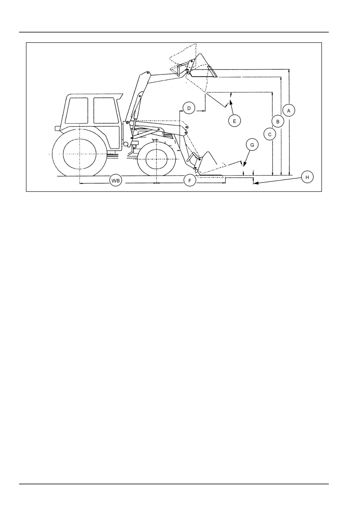
7 - SPECIFICATIONS
20022390B
1
(A) Maximum Lift Height to Pivot Pin
(F) Reach with Bucket on Ground
(B) Maximum Lift Height Under Level Bucket
(G) Maximum Rollback Angle
(C) Clearance with Bucket Dumped @ 45°
(H) Digging Depth
(D) Reach at Maximum Lift Height with Bucket
(WB) Wheelbase
Dumped @ 45°
(E) Maximum Dump Angle
7-2
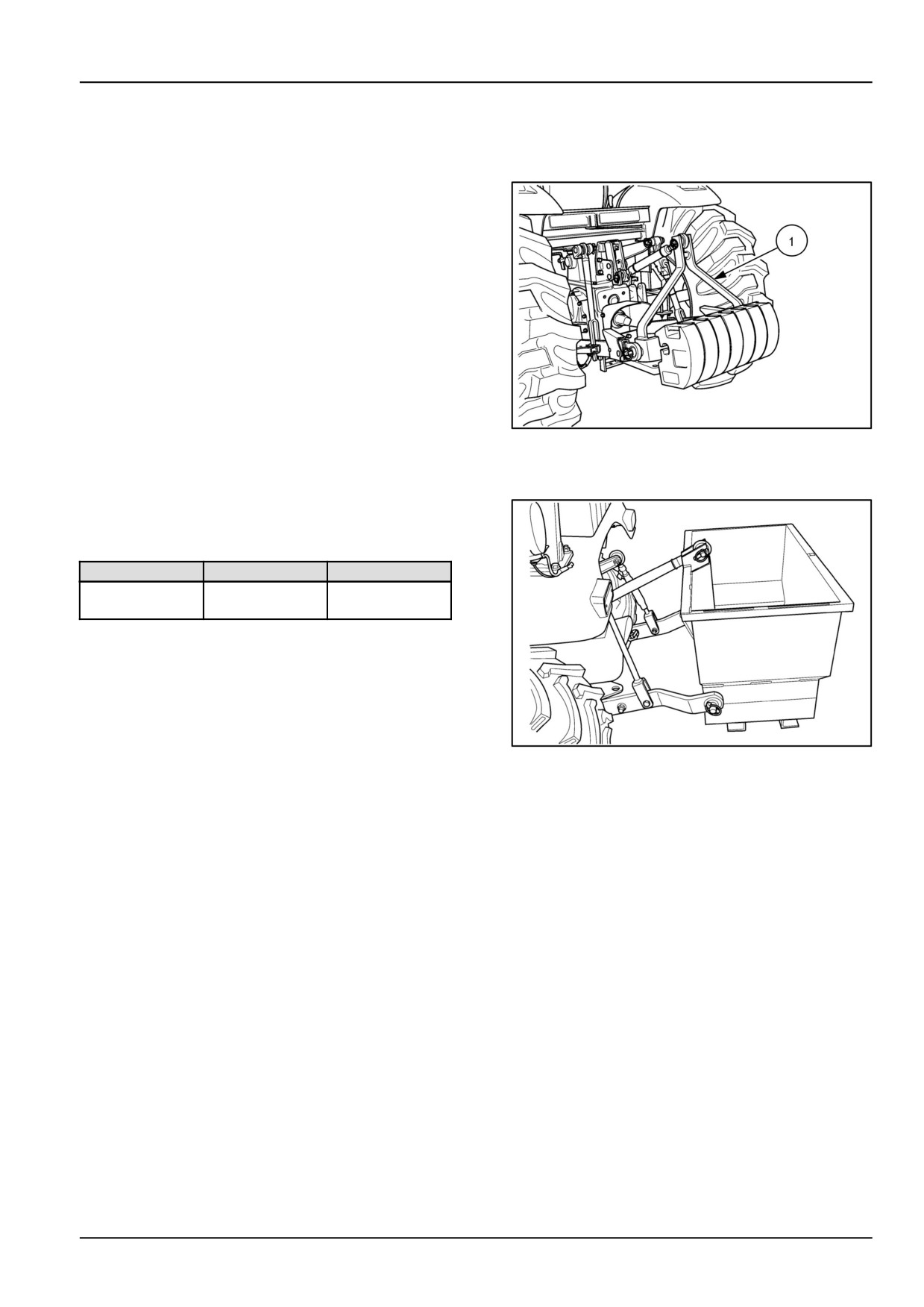
7 - SPECIFICATIONS
Weight Limitations
Rear Counter Weight Bracket (Optional)
Weight bracket (1) fits any 3 point hitch. Maximum of
seven suitcase weights.
27 kg (60 lb) each - 191.0 kg (420 lb) total
or
(2) 27 kg (60 lb)
(5) 45 kg (100 lb) - 282 kg (620 lb) total
10032795
1
Ballasting Box
A Category-1, 3-point hitch, 180 kg (400 lb) capacity bal-
lasting box may be purchased as extra equipment. Load
with sand, gravel, or similar loose ballast as needed
Weight (empty)
Weight (loaded)
3-Point Hitch
46 kg (101 lb)
228 kg (502 lb)
Ballasting Box
10036705
2
7-3

7 - SPECIFICATIONS
Liquid ballast
Recommended ballasting/counterbalance
Tires should never be filled beyond 75%. At 75% full, the
weights
liquid will come to the valve stem when the valve stem is
at its highest point at the top of the wheel.
(Optional)
WARNING
It is a common practice to add weight to the tractor by
Roll-over hazard!
filling the rear tires with liquid. A calcium chloride (CaCl2)
Before operating a tractor with a loader, bal-
and water solution is recommended due to its low freezing
last the tractor-loader combination so that a
point and greater density (weight per gallon) than pure
minimum of 25 percent of the total weight is
water.
on the rear wheels, with the rated load in the
bucket in maximum forward position.
Never exceed the total recommended weight for the trac-
Failure to comply could result in death or se-
tor. Because special equipment is required to fill the tires,
rious injury.
consult your New Holland Dealer.
W0291A
Workmaster™Hydro-Static Transmission (HST) or mechanical transmission
Ballast Type
Tire Size/Type
Approximate Added
Weight
A
Rear tire liquid ballast-
11.2 x 24, 4PR, R1 (AG)
115 kg (253 lb)
Calcium chloride,
13.6 x 16, 4PR, R3 (TURF)
151 kg (333 lb)
75% fill
41/18LL x 16.1, 6PR, R3 (TURF)
NA
5 lb solution
19.50 x 15, 6PR, R4
(INDUSTRIAL)
152 kg (334 lb)
B
Rear wheel weight
AG
Maximum of 2 weights per wheel
191 kg (420 lb) Total
@ 47.3 kg (105 lb) each.
NA
TURF
136 kg (300 lb)
NA
INDUSTRIAL
Maximum of 2 weights per wheel
@ 34 kg (75 lb) each.
C
3-Point hitch bracket and
Maximum of suitcase weights
counterweights
7 @ 27 kg (60 lb) each
191 kg (420 lb) Total
or
282 kg (620 lb)
5 @ 45 kg (100 lb) each
and 2 @ 27 kg (60 lb) each
NOTICE: Recommended ballasting choice is either 'A' or the combination of 'B' and 'C'.
7-4

7 - SPECIFICATIONS
140TL on a Workmaster™Hydro-Static Transmission (HST) or mechanical transmission (25% on Rear Axle)
Option
Bucket
Wheel
Hitch
Total
Front Axle
Rear Axle
Front Axle,
Rear Axle,
Load @
Ballast
Ballast
Weight
Load
Load
%
%
Hood
[kg (lbs)]
[kg (lbs)]
[kg (lbs)]
[kg (lbs)]
[kg (lbs)]
Height
[kg (lbs)]
A
399 kg
445 kg
116 kg
2784 kg
2088 kg
696 kg
75%
25%
Liquid in
(880 lb)
(980 lb)
(255 lb)
(6125 lb)
(4594 lb)
(1531 lb)
Rear Tires
(0) Wheel
Weights
B
499 kg
0
370 kg
2593 kg
1945 kg
648 kg
75%
25%
No Liquid in
(1100 lb)
(815 lb)
(5705 lb)
(4279 lb)
(1426 lb)
Rear Tires
(0) Wheel
Weights
A - liquid is 5 lb solution of calcium chloride to 75% full, 490 lb per tire ( 980 lb total) for grand total of 980 lb on rear
axle + additional hitch weight
B - Added counterbalance weight is added weight to the 3-point hitch only
NOTE: 43 x 16-20 R-4 tire size
7-5

7 - SPECIFICATIONS
Tire pressure
NOTICE: Tire pressure must be considered when adding weights, implements, or attachments to the tractor or dam-
age to the tractor may occur.
NOTICE: Do not install loader onto tractor equipped with galaxy turf tires. The turf tires cannot handle the added
weight of loader, and damage may occur to the tractor.
Front Tire Inflation Pressures
Tire Type
Tire Size
Inflation Pressure
Agricultural
7-14, 4PR, R1
60 - 180 kPa (8 - 26 psi)
FWD
Turf
24 x 8.5-14, 4PR, R3
60 - 150 kPa (8 - 22 psi)
FWD
25 x 8.50-14, 4PR, R3
0.6 - 2.2 bar (8 - 32 psi)
25/10.50LL x 15, 6PR, R3
60 kPa (8 psi)
Industrial (R4)
25 x 8.50-14, 6PR, R4
60 - 220 kPa (8 - 32 psi)
Rear Tire Inflation Pressures
Agricultural
11.2-24, 4PR, R1
80 - 120 kPa (12 - 18 psi)
Turf
13.6-16, 4PR, R3
80 - 100 kPa (12 - 14 psi)
41 x 14.00-20, 4PR, R3
0.8 - 1.7 bar (12 - 25 psi)
41/18LL x 16.1, 6PR, R3
40 kPa (6 psi)
Industrial (R4)
15-19.50, 6PR, R4
80 - 140 kPa (12 - 20 psi)
43 x 16-20, 4PR, R4
0.8 - 1.4 bar (12 - 20 psi)
NOTICE: Do not under-inflate tires.
WARNING
Explosion hazard!
When inflating tires, use a clip-on air chuck with a gauge, remote valve, and hose long enough to
allow you to stand to one side and NOT in front of or over the wheel assembly. Keep others out of the
DANGER AREA. Never inflate a tire beyond the maximum allowable pressure printed on the tire.
Failure to comply could result in death or serious injury.
W0059A
7-6
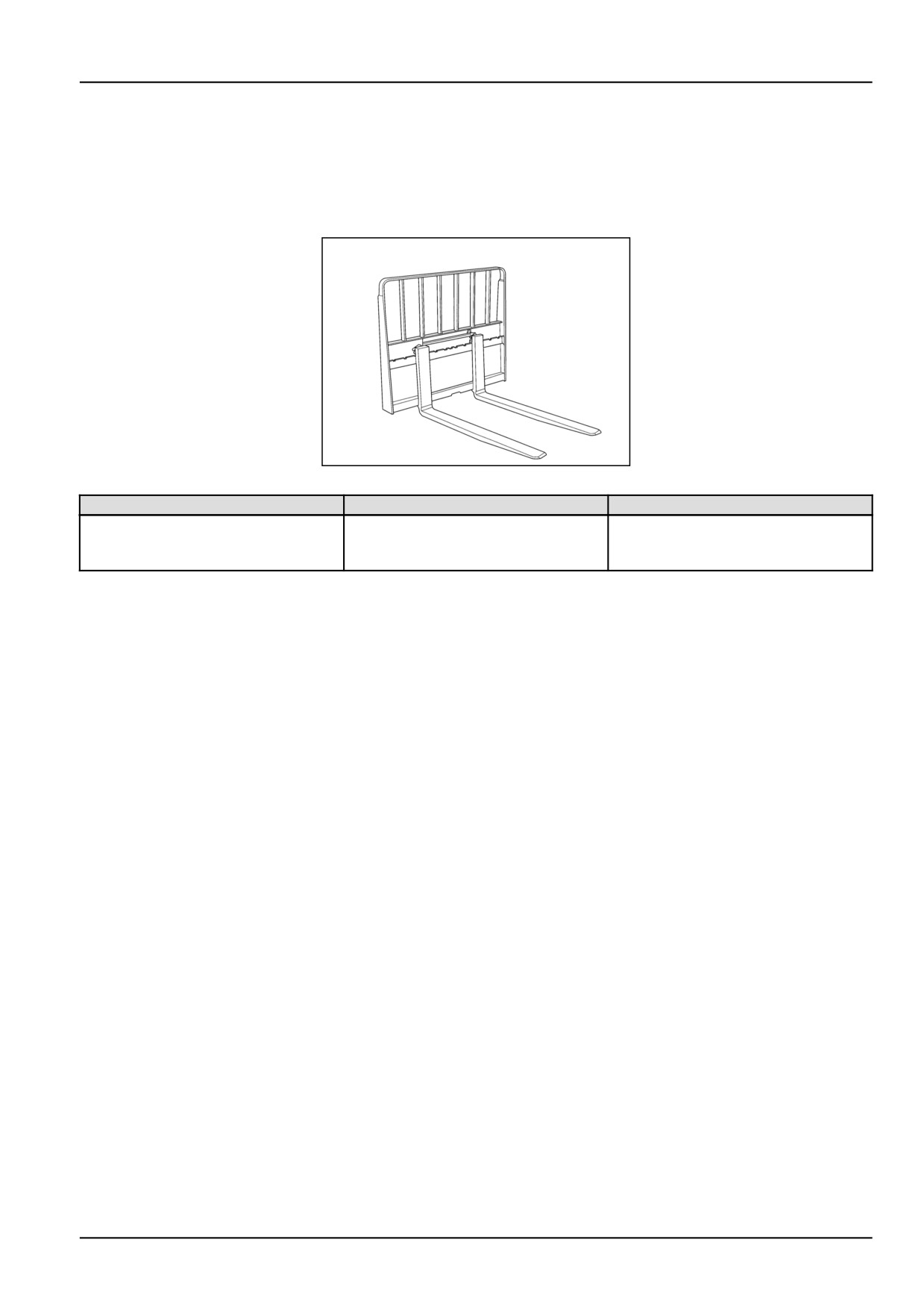
8 - ACCESSORIES
8 - ACCESSORIES###_10_###
Attachments
"Quick Attach" Only
19990486
1
Attachment Description
Size
Weight
Pallet Forks [ 1067 mm (42 in) or
1067 mm (42 in) or 1219 mm (48 in)
Frame - 104 kg (230 lb)
1219 mm (48 in)]
1067 mm (42 in) - 73 kg (160 lb)
Frame and Forks sold separately
1219 mm (48 in) - 100 kg (220 lb)
8-1
9 - FORMS AND DECLARATIONS
9 - FORMS AND DECLARATIONS###_11_###
Delivery Report- Owner Copy - Owner Copy
Delivery Date
Owner's Name
Address
Dealer's Name
Address
Unit:
Model
Product Identification
Number
Attachment:
Model
Product Identification
Number
Model
Product Identification
Number
Model
Product Identification
Number
Using the operator's manual as a guide, instruction was given as indicated by the
check marks.
( ) Safety precautions and practice
( ) Lubrication points and schedule
( ) Maintenance areas, adjustments, and schedule
( ) Field adjustments for various crop conditions
( ) Operation
( ) Use of optional equipment
( ) Preseason service
( ) End-of-season service
( ) Proper use of operator's manual
( ) Customer given operator's manual
( ) All safety shielding is installed
Dealer Representative's Signature
"I have been instructed in the operation, maintenance, and safety features of this machine as detailed in the
operator's manual."
Owner's Signature
9-1
9 - FORMS AND DECLARATIONS
Delivery report - Dealer copy - Dealer Copy
Delivery Date
Owner's Name
Address
Dealer's Name
Address
Unit:
Model
Product Identification
Number
Attachment:
Model
Product Identification
Number
Model
Product Identification
Number
Model
Product Identification
Number
Using the operator's manual as a guide, instruction was given as indicated by the
check marks.
( ) Safety precautions and practice
( ) Lubrication points and schedule
( ) Maintenance areas, adjustments, and schedule
( ) Field adjustments for various crop conditions
( ) Operation
( ) Use of optional equipment
( ) Preseason service
( ) End-of-season service
( ) Proper use of operator's manual
( ) Customer given operator's manual
( ) All safety shielding is installed
Dealer Representative's Signature
"I have been instructed in the operation, maintenance, and safety features of this machine as detailed in the
operator's manual."
Owner's Signature
9-2
Index
A
Attachments
8-1
B
Basic instructions
5-1
C
Connecting the hydraulics at the tractor . .
3-6
D
Daily inspection
5-2
Delivery report - Dealer copy - Dealer Copy
9-2
Delivery Report- Owner Copy - Owner Copy .
9-1
E
Ecology and the environment
1-5
F
Front loader and bucket - Lubricate
5-6
Front loader and bucket - Troubleshooting .
6-1
Front remote control valve
4-10
Front remote control valve - lock out
4-11
H
Hardware - Check
5-6, 5-7
Hydraulics
5-4
I
Installing the bucket level indicator
3-10
Installing the loader
3-2
Installing the quick-attach bucket .
3-8
Installing the quick-attach plate . .
3-7
International symbols
1-6
L
Liquid ballast
7-4
Loader specifications
7-1
M
Machine orientation
1-13
Machine preparation
3-1
Maintenance planning
5-6
Manual scope and required training level
1-3
N
Note to the owner
1-1
O
Operating the loader
4-1
P
Precautionary Statements
2-7
Product identification
1-12
Product overview
1-14
R
Recommended Lubricants
5-5
Removing the loader
3-14
Removing the quick-attach bucket
3-12
Removing the quick-attach plate
3-13
S
Safety features
2-14
Safety rules
2-2
Safety rules and signal word definitions
2-1
Safety signs
2-9
T
Tire pressure
7-6
Torque - Minimum Tightening Torques for Normal Assembly
1-7
Torque - Standard torque data for hydraulics
1-10
Tractor hydraulic oil reservoir - Check
5-6
W
Weight Limitations
7-3