New Holland TK65-TK75-TK76-TK85-TK95 TRACTORS. SERVICE MANUAL
TK65 -- TK75 -- TK76 -- TK85 -- TK95
TRACTORS
SERVICE MANUAL
SECTIONS
GENERAL GUIDELINES
00
ENGINE
10
CLUTCH
18
TRANSMISSIONS
21
REAR MECHANICAL TRANSMISSION
27
POWER TAKE - OFF
31
BRAKES
33
HYDRAULIC SYSTEMS
35
STEERING CLUTCHES
46
SUSPENSION AND TRACKS
48
ELECTRICAL SYSTEM
55
S
E
R
V
I
C
E
6035438100
SECTION 00 -- GENERAL -- CHAPTER 1
1
GENERAL INSTRUCTIONS
IMPORTANT NOTICE
All maintenance and repair work described in this manual must be performed exclusively by NEW HOLLAND
service technicians, in strict accordance with the instructions given and using any specific tools necessary.
Anyone performing the operations described herein without strictly following the instructions is personally re-
sponsible for any eventual injury or damage to property.
BATTERY
Before carrying out any kind of service operations, disconnect and isolate the battery negative lead, unless other-
wise requested for specific operations (e.g.: operations that require the engine running). Once the specific oper-
ation has been completed, disconnect the lead in order to complete the operation.
SHIMMING
For each adjustment operation, select adjusting shims and measure individually using a micrometer, then add
up the recorder values. Do not rely on measuring the entire shimming set, which may be incorrect, or the rated
value indicated for each on shim.
ROTATING SHAFT SEALS
For correct rotating shaft seal installation, proceed as follows:
--
before assembly, allow the seal to soak in the oil it will be sealing for at least thirty minutes;
--
thoroughly clean the shaft and check that the working surface on the shaft is not damaged;
--
position the sealing lip facing the fluid; with hydrodynamic lips, take into consideration the shaft rotation direc-
tion and position the grooves so that they will deviate the fluid towards the inner side of the seal;
--
coat the sealing lip with a thin layer of lubricant (use oil rather than grease) and fill the gap between the sealing
lip and the dust lip on double lip seals with grease;
--
insert the seal in its seat and press down using a flat punch; do not tap the seal with a hammer or mallet;
--
whilst inserting the seal, check that the it is perpendicular to the seat; once settled, make sure that it makes
contact with the thrust element, if required;
--
to prevent damaging the seal lip on the shaft, position a protective guard during installation operations.
O--RING ìSEALSî
Lubricate the O--RING seals before inserting them in the seats, this will prevent them from overturning and twist-
ing, which would jeopardise sealing efficiency.
SEALING COMPOUNDS
Apply one of the following sealing compounds on the mating surfaces marked with an X: RTV SILMATE, RHO-
DORSIL CAF 1 or LOCTITE 510 or SILASTIC AP black.
Before applying the sealing compound, prepare the surfaces as follows:
--
remove any incrustations using a wire brush;
--
thoroughly de--grease the surfaces using one of the following cleaning agents: trichlorethylene, petrol or a
water and soda solution.
BEARINGS
When installing bearings it is advised to:
--
heat the bearings to 80 to 900C (176 to 1940F) before fitting on the shafts;
--
allow the bearings to cool before installing them from the outside.
SPRING PINS
When fitting split socket elastic pins, ensure that the pin notch is positioned in the direction of the force required
to stress the pin.
Spiral spring pins do not require special positioning.
603.54.381.00 -- 05 -- 2001
2
SECTION 00 -- GENERAL -- CHAPTER 1
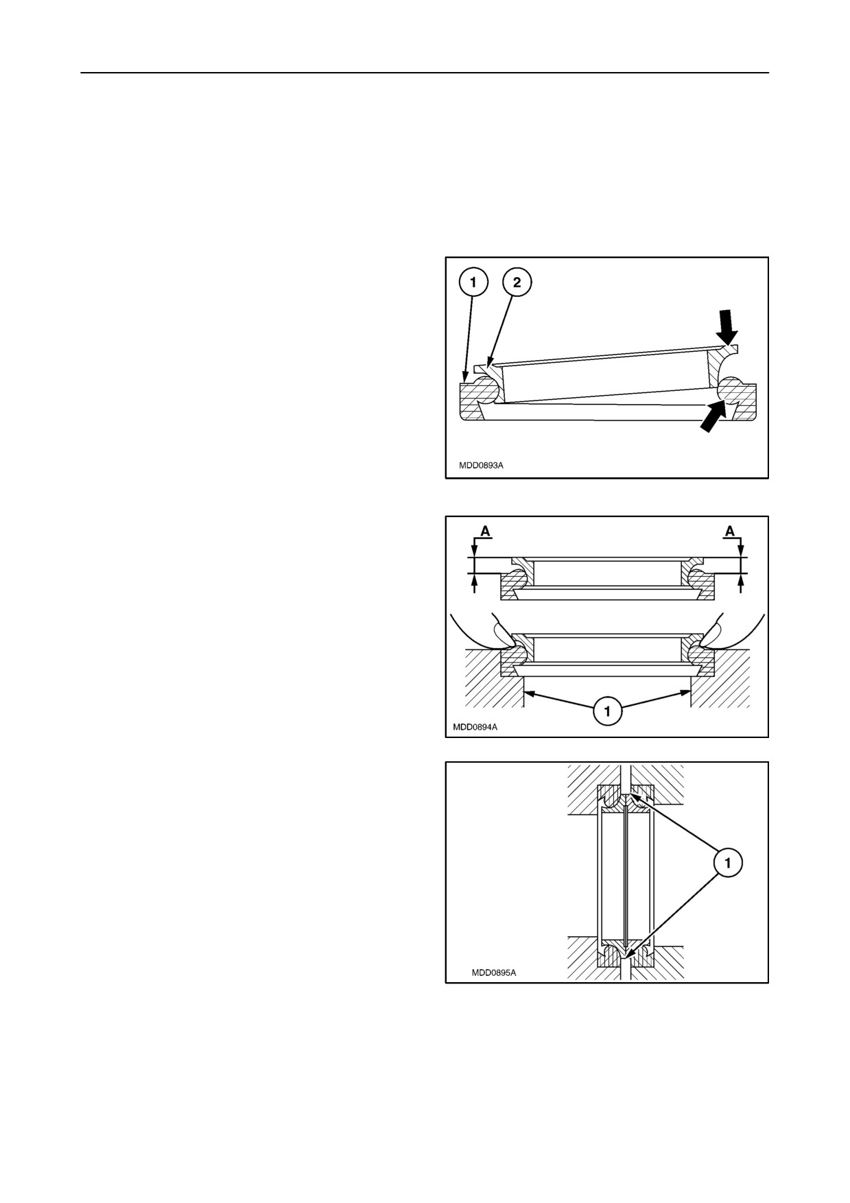
FRONT SEALS
Carefully check the metal rings, making sure that the
sealing surfaces show no signs of scoring, dents or
wear caused by ring pair misalignment or surface
flatness errors.
Even if only one of the rings is faulty, change the en-
tire seal.
Never pair a used ring with a new one or use different
pairs of rings.
To fit the seals, proceed as follows.
1. Eliminate any sharp edges or burr and carefully
clean the seats for the rubber rings.
2. Thoroughly clean the rings on the seals.
3. Insert each metal ring (2) on the respective
rubber ring (1), as shown in the drawing, acting
on the points indicated by the arrows.
1
4. Make sure that the metal ring is fitted correctly,
checking that measurement (A) is constant on all
of the circumference.
5. Assemble each pair of rings in their respective
seats (1), manually positioning the rubber ring
(as shown in figure
2
6. Before terminating assembly operations, clean
the sealing surfaces (1) with a clean (not frayed)
cloth and pour a thin covering of fluid oil over the
surfaces.
3
603.54.381.00 -- 05 -- 2001
SECTION 00 -- GENERAL -- CHAPTER 1
3
SPARE PARTS
Only use original NEW HOLLAND spare parts bearing the logo shown below.
4
Only original spare parts guarantee the same quality, duration and safety as they are the same parts that are
assembled during production.
Only original NEW HOLLAND parts can offer this guarantee.
When ordering spare parts, always provide the following information:
--
vehicle model (commercial name) and frame number;
--
engine type and number;
--
part number of the ordered part, which can be found in the ìMicrofichesî or the ìSpare Parts Catalogueî, used
for order processing.
TOOLS
The tools that NEW HOLLAND propose and illustrate in this manual are:
--
specifically researched and designed for use with NEW HOLLAND vehicles;
--
essential for reliable repair operations;
--
accurately built and rigorously tested so as to offer efficient and long--lasting operation.
By using these tools, repair personnel will benefit from:
--
operating in optimal technical conditions;
--
obtaining the best results;
--
saving time and effort;
--
working in safe conditions.
CAUTION
Wear limit values indicated for certain parts are recommended, but not binding. The terms ìfrontî, ìrearî, ìright--
handî and ìleft--handî (when referred to different parts) are intended as seen from the driving position with the
vehicle in the normal direction of movement.
MOVING THE TRACTOR WITH THE BATTERY REMOVED
External power supply cables should only be connected to the respective positive and negative cable terminals,
using efficient clamps that guarantee adequate and secure contact.
Disconnect all services (lights, windshield wipers, etc.) before starting the vehicle.
If the vehicle electrical system requires checking, carry out operations with the power supply connected; once
checking is completed, disconnect all services and switch off the power supply before disconnecting the cables.
603.54.381.00 -- 05 -- 2001
4
SECTION 00 -- GENERAL -- CHAPTER 1
SAFETY REGULATIONS
WARNING AND DANGER SYMBOL
This warning symbol points out important messages
concerning your safety.
Carefully read the following safety regulations and
observe advised precautions in order to avoid poten-
tial hazards and safeguard your health and safety.
In this manual the symbol is accompanied by the fol-
lowing key--words:
CAUTION -- Warnings concerning unsuitable repair
operations that may jeopardise the safety of Service
personnel.
DANGER Specific warnings concerning potential
hazards for operator safety or for other persons di-
5
rectly or indirectly involved.
--
Do not carry out repair operations with someone
sitting in the driverís seat, unless the person is a
trained technician who is assisting with the oper-
ACCIDENT PREVENTION
ation in question.
Most accidents or injuries that occur in workshops
--
Do not operate the vehicle or use any of the im-
are the result of non--observance of simple and fun-
plements from different positions, other than the
damental safety regulations. For this reason, IN
driverís seat.
MOST CASES THESE ACCIDENTS CAN BE
--
Do not carry out operations on the vehicle with
AVOIDED by foreseeing possible causes and conse-
the engine running, unless specifically indicated.
quently acting with the necessary caution and care.
--
Stop the engine and check that the hydraulic cir-
Accidents may occur with all types of vehicles, re-
cuits are pressure--free before removing caps,
gardless of how well it was designed and built.
covers, valves, etc.
A careful and judicious service technician is the best
--
All repair and maintenance operations must be
guarantee against accidents.
carried out using extreme care and attention.
Precise observance of the most basic safety rule is
--
Service steps and platforms used in the work-
normally sufficient to avoid many serious accidents.
shop or elsewhere should be built according to
DANGER. Never carry out any cleaning, lubrication
standard accident prevention regulations.
or maintenance operations when the engine is run-
--
Disconnect the batteries and label all controls to
ning.
indicate that the vehicle is being serviced. Any
parts that are to be raised must be locked in posi-
tion.
SAFETY REGULATIONS
--
Do not check or fill fuel tanks, accumulator bat-
teries, nor use starting liquid when smoking or
near naked flames, as these fluids are inflam-
GENERAL GUIDELINES
mable.
--
Carefully follow specified repair and mainten-
--
Brakes are inoperative when manually released
ance procedures.
for repair or maintenance purposes. Use blocks
or similar devices to control the machine in these
--
Do not wear rings, wristwatches, jewellery, un-
conditions.
buttoned or loose articles of clothing such as:
ties, torn clothing, scarves, open jackets or shirts
--
The fuel nozzle should always be in contact with
with open zips that may remain entangled in
the filling aperture. Maintain this position until fill-
moving parts. It is advised to wear approved
ing operations are completed in order to avoid
safety clothing, e.g.: non--slip footwear, gloves,
possible sparks caused by the accumulation of
safety goggles, helmets, etc.
static electricity.
603.54.381.00 -- 05 -- 2001
SECTION 00 -- GENERAL -- CHAPTER 1
5
--
Only use specified towing points for towing the
driverís seat. The operator must maintain visual
tractor. Connect parts carefully. Make sure that
contact with the service technician at all times.
all pins and/or locks are secured in position be-
--
If operating outside the workshop, position the
fore applying traction. Never remain near the
vehicle on a flat surface and lock in position. If
towing bars, cables or chains that are operating
working on a slope, lock the vehicle in position.
under load.
Move to a flat area as soon as is safely possible.
--
Transport vehicles that cannot be driven using a
--
Damaged or bent chains or cables are unreliable.
trailer or a low--loading platform trolley, if avail-
Do not use them for lifting or towing. Always use
able.
suitable protective gloves when handling chains
--
When loading or unloading the vehicle from the
or cables.
trailer (or other means of transport), select a flat
area capable of sustaining the trailer or truck
--
Chains should always be safely secured. Make
wheels. Firmly secure the tractor to the truck or
sure that the hitch--up point is capable of sustain-
trailer and lock the wheels in the position used by
ing the load in question. Keep the area near the
the carrier.
hitch--up point, chains or cables free of all by-
standers.
--
Electric heaters, battery--chargers and similar
equipment must only be powered by auxiliary
--
Maintenance and repair operations must be car-
power supplies with efficient ground insulation to
ried out in a CLEAN and DRY area. Eliminate any
avoid electrical shock hazards.
water or oil spillage immediately.
--
Always use suitable hoisting or lifting devices
--
Do not create piles of oil or grease--soaked rags
when raising or moving heavy parts.
as they represent a serious fire hazard. Always
--
Take extra care if bystanders are present.
store rags in a closed metal container.
--
Never pour gasoline or diesel oil into open, wide
Before starting the vehicle or implements, make
sure that the driverís seat is locked in position.
or low containers.
Also check that there are no persons within the
--
Never use gasoline, diesel oil or other inflam-
tractor or implement range of action.
mable liquids as cleaning agents. Use non--in-
flammable, non toxic commercially available sol-
--
Empty pockets of all objects that may fall unob-
vents.
served into the vehicle parts.
--
Wear safety goggles with side guards when
--
In the presence of protruding metal parts, use
cleaning parts with compressed air.
protective goggles or goggles with side guards,
--
Limit the air pressure to a maximum of 2.1 bar
helmets, special footwear and gloves.
(30.46 psi), according to local regulations.
--
When welding, use protective safety devices:
--
Do not run the engine in confined spaces without
tinted safety goggles, helmets, special overalls,
suitable ventilation.
gloves and footwear. All persons present in the
--
Do not smoke, use naked flames, or cause
area where welding is taking place must wear
sparks in the area when fuel filling or handling
tinted goggles. NEVER LOOK DIRECTLY AT
highly inflammable liquids.
THE WELDING ARC WITHOUT SUITABLE
EYE PROTECTION.
--
Never use naked flames for lighting when work-
ing on the machine or checking forìleaks.
--
Metal cables tend to fray with repeated use. Al-
--
All movements must be carried out carefully
ways use suitable protective devices (gloves,
when working under, on or near the vehicle.
goggles, etc.) when handling cables.
Wear protective equipment: helmets, goggles
--
Handle all parts carefully. Do not put your hands
and special footwear.
or fingers between moving parts. Wear suitable
--
When carrying out checks with the engine run-
safety clothing
-- safety goggles, gloves and
ning, request the assistance of an operator in the
shoes.
603.54.381.00 -- 05 -- 2001
6
SECTION 00 -- GENERAL -- CHAPTER 1
START UP
enough to penetrate the skin; Therefore, NEVER
USE HANDS TO CHECK FOR LEAKS. Use a
--
Never run the engine in confined spaces that are
piece of cardboard or wood for this purpose. If
not equipped with adequate ventilation for ex-
any liquid penetrates skin tissue, call for medical
haust gas extraction.
aid immediately. Failure to treat this condition
--
Never place the head, body, limbs, feet, hands or
with correct medical procedure may result in seri-
fingers near fans or rotating belts.
ous infection or dermatosis.
ENGINE
--
In order to check the pressure in the system use
suitable instruments.
--
Always loosen the radiator cap slowly before re-
moving it to allow any remaining pressure in the
system to be discharged. Filling up with coolant
WHEELS AND TYRES
should only be carried out with the engine
--
Make sure that the tyres are correctly inflated at
stopped or idling (if hot).
the pressure specified by the manufacturer.
--
Never fill up with fuel when the engine is running,
Periodically check the rims and tyres for dam-
especially if hot, in order to prevent the outbreak
age.
of fire as a result of fuel spillage.
--
Stand away from (at the side of) the tyre when
--
Never check or adjust fan belt tension when the
checking inflation pressure.
engine is running.
--
Only check pressure when the tractor is un-
Never adjust the fuel injection pump when the ve-
loaded and the tyres are cold, to avoid incorrect
hicle is moving.
readings as a result of over--pressure. Do not use
--
Never lubricate the vehicle when the engine is
parts of recovered wheels as incorrect welding
running.
brazing or heating may weaken and eventually
cause damage to the wheel.
ELECTRICAL SYSTEMS
--
Never cut or weld a rim mounted with an inflated
--
If it is necessary to use auxiliary batteries, re-
tyre.
member that both ends of the cables must be
--
To remove the wheels, lock both the front and
connected as follows: (+) with (+) and (--) with (--).
rear vehicle wheels. After having raised the ve-
Avoid short--circuiting the terminals. GAS RE-
hicle, position supports underneath, according to
LEASED FROM BATTERIES IS HIGHLY IN-
regulations in force.
FLAMMABLE. During charging, leave the bat-
tery compartment uncovered to improve
--
Deflate the tyre before removing any objects that
ventilation. Never check the battery charge using
may be jammed in the tyre tread.
ìjumpersî
(metal objects placed on the ter-
--
Never inflate tyres using inflammable gases; as
minals). Avoid sparks or flames near the battery
this may result in explosions and injury to by-
zone. Do not smoke to prevent explosion haz-
standers.
ards.
--
Before servicing operations, check for fuel or
REMOVAL AND RE--FITTING
current leaks. Eliminate any eventual leaks be-
fore proceeding with work.
--
Lift and handle all heavy parts using suitable ho-
--
Never charge batteries in confined spaces. Make
isting equipment. Make sure that parts are sus-
sure that there is adequate ventilation in order to
tained by appropriate hooks and slings. Use the
prevent accidental explosion hazards as a result
hoisting eyebolts for lifting operations. Extra care
of the accumulation of gases released during
should be taken if persons are present near the
charging operations.
load to be lifted.
--
Always disconnect the batteries before perform-
--
Handle all parts carefully. Do not put your hands
ing any kind of servicing on the electrical system.
or fingers between parts. Wear suitable safety
clothing -- safety goggles, gloves and shoes.
HYDRAULIC SYSTEMS
--
Avoid twisting chains or metal cables. Always
--
A liquid leaking from a tiny hole may be almost
wear safety gloves when handling cables or
invisible but, at the same time, be powerful
chains.
603.54.381.00 -- 05 -- 2001

SECTION 00 -- GENERAL -- CHAPTER 1
7
CONSUMABLES
QUANTITY
RECOMMENDED
COMPONENT TO BE FILLED
3
NEW HOLLAND
INTERNATIONAL
dm
NEW HOLLAND
OR TOPPED UP
SPECIFICATIONS
SPECIFICATIONS
(gallons)
PRODUCTS
Cooling system:
Water & liquid
AMBRA
--
models TK65, TK75
10.5
(2.31)
NH 900 A
--
AGRIFLU
--
models TK76, TK85, TK95
13.0
(2.86)
50% + 50%
Fuel tank:
Decanted and fil-
--
models TK65, TK75
80
(17.6)
--
--
tered diesel fuel
--
models TK76, TK85, TK95
129
(28.38)
Engine sump:
without filter:
NH 330G
--
models TK65, TK75
6.7
(1.47)
AMBRA
(SAE 15W--40)
API CF--4/SG
SUPER GOLD
--
models TK76, TK85, TK95
10.5
(2.31)
CCMC D4
15W -- 40 oil or
NH 24G
MIL--L--2104E
with filter:
10W -- 30
(SAE 10W--30)
--
models TK65, TK75
7.3
(1.61)
--
models TK76, TK85, TK95
11.2
(2.46)
API CE CCMC D4
AMBRA
Steering clutches
1.4
(0.31)
NH 301 C
MIL--L--2104C
SUPER oil 10W
SAE 10W
Transmission:
(gears, bevel drive,
brakes and hydraulic
lift)
API GL4
33.3
(7.32)
AMBRA MULTI F
--
models TK65, TK75
NH 420 A
ISO 46/68
oil
--
models TK76, TK85, TK95
39.0
(7.92)
SAE 20W--30
Track tension wheel,
carriage rollers, track support
rollers
--
API GL5
Final drives
AMBRA
NH 520 A
MIL--L--2105D
(each)
2.0
(0.44)
HYPOIDE 90 oil
SAE 80W--90
Grease fittings
--
AMBRA GR9
NH 710 A
NLGI 2
grease
603.54.381.00 -- 05 -- 2001
8
SECTION 00 -- GENERAL -- CHAPTER 1
603.54.381.00 -- 05 -- 2001
SECTION 10 -- ENGINE -- CHAPTER 1
1
SECTION 10 -- ENGINE
Chapter 1 -- Engine
CONTENTS
Section
Description
Page
10 000
General specifications
2
Main data
5
Torque settings
24
Tools
25
Sections
27
Lubrication and cooling system diagrams
31
Troubleshooting
34
10 001
10
Engine. Removal--Installation
38
10 001
30
Engine. Compression test
42
10 001
54
Engine. Disassembly--Assembly
43
10 101
53
Valve guides. Replacement
78
10 101
60
Injector sleeve. Replacement
82
10 102
70
Front engine oil seal. Removal--Installation
87
10 106
12
Valve/rocker arm clearance
91
10 216
10
Rear fuel tank -- models TK 65 and TK 75. Removal--Installation
94
10 216
10
Rear fuel tank -- models TK 76, TK 85 and TK 95. Removal--Installation
97
10 216
40
Front fuel tank -- models TK 65 and TK 75. Removal--Installation
100
10 216
40
Front fuel tank -- models TK 76, TK 85 and TK 95. Removal--Installation
102
10 218
30
Engine injectors. Removal--Installation
104
10 246
14
Bosch injection pump. Removal--Installation timing and air bleeding check
106
10 254
44
Exhaust pipe. Removal--Installation
113
10 402
11
Coolant pump. Removal--Installation with radiator removed
114
10 402
28
Coolant pump. Overhaul
115
10 402
30
Thermostat. Removal--Installation
116
10 406
10
Radiator. Removal--Installation
117
10 414
10
Coolant pump and generator drive belt. Adjustment
120
603.54.381.00 -- 05 -- 2001
2
SECTION 10 -- ENGINE -- CHAPTER 1
GENERAL SPECIFICATIONS
3 cylinders
4 cylinders
Engine, technical type:
--
model TK 65 -- type 8035.05.421 (BOSCH pump)
See data on page 6--7
--
--
model TK 75 -- type 8035.25.421 (BOSCH pump)
See data on page 8--9
--
--
model TK 76 -- type 8045.06.421/521 (BOSCH pump)
--
See data on page 10--11
--
model TK 85 -- type 8045.05.421/521 (BOSCH pump)
--
See data on page 12--13
--
model TK 95 -- type 8045.25L.421 (BOSCH pump)
--
See data on page 14--15
Cycle
diesel, 4--stroke
Injection
direct
Number of on--line cylinders
3
4
Cylinder liners
dry force--fitted in cylinder block
Piston diameter
--
models TK 65, TK 75
104 mm (4.0945 in.)
--
--
model TK 76
--
100 mm (3.937 in.)
--
models TK 85, TK 95
--
104 mm (4.0945 in.)
Piston stroke
115 mm (4.37 in.)
Total displacement:
--
model TK 65
2931 cm3 (0.6447 gal.)
--
--
model TK 75
2931 cm3 (0.6447 gal.)
--
--
model TK 76
--
3613 cm3 (0.7947 gal.)
--
model TK 85
--
3908 cm3 (0.8596 gal.)
--
model TK 95
--
3908 cm3 (0.8596 gal.)
Compression ratio for models TK 65, TK 76 and TK 85
17 to 1 normally aspirated
Compression ratio for models TK 75 and TK 95
16.5 to 1 turbocharged
Maximum power:
--
model TK 65
44.5 kW (60 Hp)
--
--
model TK 75
54 kW (72 Hp)
--
--
model TK 76
--
53 kW (71 Hp)
--
model TK 85
--
58.8 kW (80 Hp)
--
model TK 95
--
66.5 kW (90 Hp)
Maximum power speed -- models TK 65, TK 75
2300 rpm
Maximum power speed -- TK 76, TK 85, TK 95
2500 rpm
Maximum torque speed -- model TK 65
1400 rpm
--
Maximum torque speed -- model TK 75
1400 rpm
--
Maximum torque speed -- model TK 76
--
1500 rpm
Maximum torque speed -- model TK 85
--
1500 rpm
Maximum torque speed -- model TK 95
--
1500 rpm
Number of main bearings
4
5
Sump pan
structural, cast iron
(continued)
603.54.381.00 -- 05 -- 2001

SECTION 10 -- ENGINE -- CHAPTER 1
3
(continued)
GENERAL SPECIFICATIONS
3 cylinders
4 cylinders
Lubrication system
forced, with gear pump
Pump drive
camshaft
Engine speed/oil pump speed ratio
2:1
Oil cleaning
mesh filter on oil intake and filtering car-
tridge on delivery line
Normal oil pressure with motor warmed--up and running at
maximum speed:
For models TK 65, TK 76, TK 85
2.9 to 3.9 bar (42.1 to 56.6 psi)
For models TK 75, TK 95 (starting pressure)
6 bar (87 psi)
Pressure relief valve
incorporated in oil pump housing
Valve initial opening pressure
3.5 bar (50.8 psi)
For further lubrication technical data
See page 23
Cooling system
coolant circulation
Radiator on models TK 65, TK 75
3 lines of vertical pipes with copper fins
Radiator on models TK 76, TK 85, TK 95
4 lines of vertical copper pipes
Fan, attached to coolant pump pulley
intake, 4--blade in sheet--metal
Coolant pump
centrifugal vane--type
Engine speed/coolant pump speed ratio
1:1.403
Temperature control
thermostat
Coolant thermometer
coloured scale divided into 3 sections
Temperature ranges corresponding to each section:
--
initial white section
30 to 65oC (86 to 149oF)
--
middle green section (normal working conditions)
65 to 105oC (149 to 221oF)
--
final red section
105 to 115oC (221 to 239oF)
For further cooling system technical data
See page 23
Rev counter
incorporated in control panel
Operating system
from gear on camshaft
Hour counter calibrated for engine speed of
1800 rpm
(continued)
603.54.381.00 -- 05 -- 2001
4
SECTION 10 -- ENGINE -- CHAPTER 1
(continued)
GENERAL SPECIFICATIONS
3 cylinders
4 cylinders
Timing system
overhead valves operated by tappets, rods
and rocker arms via the camshaft located
in the engine block; the camshaft is driven
by the crankshaft using helical gears
Inlet:
--
start: before TDC
12o
--
end: after BDC
31o
Exhaust:
--
start: before BDC
50o
--
end: after TDC
16o
valve--rocker arm clearance for timing check
0.45 mm (0.248 in.)
valve--rocker arm clearance (with engine cold):
--
intake
0.30
0.05 mm (0.1654
0.0276 in.)
--
exhaust
0.30
0.05 mm (0.1654
0.0276 in.)
For further timing system technical data
See page 20
Fuel system
Air cleaning
dual cartridge dry air filter, with clogged
filter indicator with centrifugal pre--filter
and automatic dust ejector
Fuel pump
double diaphragm
Fuel filtering
through wire filter in fuel supply pump, and
replaceable cartridge on delivery line to
injection pump
Minimum fuel flow rate with pump shaft rotating at 1600 rpm .
100 litres/hour (22 gal./hour)
Cam operated
engine timing
BOSCH injection pump
rotating distributor type
All--speed governor, incorporated in pump:
BOSCH
centrifugal counterweights
Automatic advance regulator, incorporated in pump:
BOSCH
hydraulic
For further fuel system technical data:
Fixed advance (pump setting for start of delivery before TDC)
-- Pressure setting -- Injection order, and other information
regarding the BOSCH pump
refer to the data for the relevant engine
type in the table on page 2
603.54.381.00 -- 05 -- 2001
SECTION 10 -- ENGINE -- CHAPTER 1
5
FUEL SYSTEM DATA
Turbocharger (models TK 75, TK 95):
--
GARRETT type
TA 3118--0.82 A/R--57
Injection pump
rotating distributor with speed governor
and advance variator incorporated
BOSCH pump:
--
model TK 65
VE 3/11 F 1150 L 766 -- 99441586
--
model TK 75
VE 3/11 F 1150 L 764 -- 99441587
--
model TK 76
VE 4/11 F 1250 L 794 -- 99472104
--
model TK 76
VE 4/11 F 1250 L 810 -- 500324959
--
model TK 85
VE 4/11 F 1250 L 773 -- 99472102
--
model TK 85
VE 4/11 F 1250 L 787 -- 500324962
--
model TK 95
VE 4/11 F 1250 L 850 -- 500358111
Direction of rotation
counter--clockwise
Injection order
1--2--3 (TK 65, TK 75) 1--3--4--2 (TK 76,
TK 85, TK 95)
TK 65
TK 75
TK 85
TK 95
TK 76
Injectors:
BOSCH type
500307714
500317389
--
Nozzle holder type
4791124
(KBEL83S35)
--
Nozzle type
99469341
(DLLA132S1320)
500317390
(DLLA132S
1335)
Number of nozzle holes
5
5
Nozzle hole diameter
mm (in.)
0.23
(0.0091)
0.21
(0.0083)
Calibration pressure
bar (psi)
260 to 272 (3771 to 3945)
260 to 272
(3771 to
3945)
Delivery lines for BOSCH pump
--
type
99441952
--
99449006
--
--
Line dimension
mm (in.)
6x1.75x540
6x1.75x530
6x1.75x530
--
(0.2362x0.0689x21.260)
(0.2362x
(0.2362x
0.0689x
0.0689x
20.866)
20.866)
603.54.381.00 -- 05 -- 2001
6
SECTION 10 -- ENGINE -- CHAPTER 1
MODEL TK 65 -- CALIBRATION DATA FOR BOSCH INJECTION PUMP
TYPE VE 3/11 F 1150 L 766 -- 99441586
ASSEMBLY DATA
CALIBRATION TEST CONDITIONS
Pump timing on engine: delivery start 9o
0.5o before
Test bench conforming to ISO 4008/1 .../2
TDC of cylinder 1 compression stroke.
Injectors conforming to ISO
7440--A61
--
Plunger pre--lift for timing on engine: 1 mm (0.0394
(1.688.901.020 with calibrated pad
0.6 mm --
in.) from BDC (with tools 291754 -- 291755).
0.0236 in.).
Cylinder No.1 delivery line union on pump: marked
Injector pressure setting 172 to 175 bar (2495 to
with letter A.
2538 psi).
Fuel supply pressure:
ASSEMBLY DIMENSIONS
0.35 + 0.05 bar (5.1 + 0.7 psi).
Pipes (conforming to ISO 4093.2):
SYMBOL
VHA
MS
ya
yb
6x2x840mm(0.2362x0.0787x33.071in.).
mm
30.1
--
36.5 to 38.5
40.4 to 45.6
Graduate drain time
: 30î.
(in.)
(1.185)
(1.437 to
(1.5905 to
1.5157)
1.7953)
Test liquid: ISO 4113 at a temperature of 45o
1oC
(113o
33.8oF) at outlet.
1. START OF DELIVERY
Plunger pre--lift from TDC:
Pump rotation (viewed from drive side):
Injection order:1--2--3
mm --
counter--clockwise
2. ADVANCE REGULATOR STROKE
rpm: 1220
Advance stroke: 0.7 to 1.1 mm (0.0276 to 0.0433 in.)
3. FUEL SUPPLY PUMP PRESSURE
rpm: 1220
Internal pressure: 7.9 to 8.5 bar (114.5 to 123.3 psi)
4. FULL LOAD DELIVERY
rpm: 700
Delivery per 1000 shots: 66.7 to 67.7 cm3 (0.0147 to 0.0149 gal.)
Spread:
3.5 cm3 (0.0008 gal.)
5. SPREAD GOVERNOR AT IDLE SPEED
rpm: 325
Delivery per 1000 shots: 16.3 to 17.3 cm3 (0.0036 to 0.0038 gal.)
Spread:
5.5 cm3 (0.0012 gal.)
6. SPREAD GOVERNOR AT MAXIMUM SPEED
rpm: 1200
Delivery per 1000 shots: 48.5 to 49.5 cm3 (0.0107 to 0.0109 gal.)
Spread: cm3 --
7. DELIVERY AT STARTING SPEED
rpm: 100
Delivery per 1000 shots: 60 to 100 cm3 (0.0132 to 0.022 gal.)
8. TRANSFER PRESSURE PROGRESSION
rpm
1220
400
Internal pressure
bar (psi)
7.9 to 8.5 (114.6 to 123.3)
3.4 to 4.4 (49.3 to 63.8)
9. INJECTION ADVANCE PROGRESSION
rpm
1220
1260
Advance stroke
mm (in.)
0.7 to 1.1 (0.276 to 0.0433)
1.3 to 1.9 (0.0512 to 0.0748)
10. BACKFLOW
rpm
400
1150
Backflow
cm3 (gal.)/10 sec
16 to 28 (0.0035 to 0.0062)
20 to 36 (0.0044 to 0.0079)
(continued)
Note: the values shown above in brackets must be used for checking purposes only.
603.54.381.00 -- 05 -- 2001
SECTION 10 -- ENGINE -- CHAPTER 1
7
(continued)
11. DELIVERY PROGRESSION
rpm
Delivery per 1000 shots: cm3 (gal.)
1270
0 to 3 (0 to 0.0007)
1200
48.5 to 49.5 (0.0107 to 0.0109)
700
66.7 to 67.7 (0.0147 to 0.0149)
1150
64.4 to 68.4 (0.0142 to 0.0150)
12. DELIVERY CHECK AT IDLE SPEED
rpm
325
275
Delivery per 1000
shots:
cm3 (gal.)
16.3 to 17.3 (0.0036 to 0.0038)
46 to 47 (0.0101 to 0.0103)
13. ZERO CAPACITY (STOP)
rpm
Voltage (volts)
Delivery per 1000 shots: cm3 (gal.)
325
0
0 to 3 (0 to 0.0070)
14. AUTOMATIC START SUPPLEMENT
rpm
Delivery per 1000 shots: cm3 (gal.)
100
60 to 100 (0.0132 to 0.022)
270
59 to 69 (0.0130 to 0.0152)
Note: the values shown above in brackets must be used for checking purposes only.
BENCH TEST PERFORMANCE DATA
Test conditions
Fixed advance before TDC cylinder No.1 in compression
Relative humidity 70o/o
5.
stroke: (see previous page)
Engine without fan, air filter and exhaust silencer.
Ambient temperature 20
3 oC (68
37.4oF).
Atmospheric pressure 740
5 mm (29.1339
0.1968 in.)
Specific gravity of diesel fuel 840 g/l at a tem-
mercury.
perature of 15oC (59oF).
Fuel consum-
Engine speed
Power output with engine run--in for a total of:
Throttle
ption
lever
Braking load
applied
Production speed
50 hours (total)
position
rpm
kW (Hp)
kW (Hp)
kg (lbs.)/h
9.9 to 10.5
For maximum power
43 to 45.6
Maximum
2300
42
(57.1)
(21.83 to
output
(58.5 to 62)
23.15)
6.4 to 6.8
30 to 31.8
Maximum
For maximum torque
1400
29.4
(40)
(14.11 to
(40.8 to 43.2)
23.15)
2450 to
Maximum
None (no--load)
--
--
--
2500
Minimum
None (no--load)
625 to 675
--
--
--
603.54.381.00 -- 05 -- 2001
8
SECTION 10 -- ENGINE -- CHAPTER 1
MODELS TK 75 -- CALIBRATION DATA FOR BOSCH INJECTION PUMP
TYPE VE 3/11 F 1150 L 764 -- 99441587
ASSEMBLY DATA
CALIBRATION TEST CONDITIONS
Pump timing on engine: delivery start 6o
0.5o be-
Test bench conforming to ISO 4008/1 .../2
fore TDC of cylinder 1 compression stroke.
Injectors conforming to ISO
7440--A61
--
Plunger pre--lift for timing on engine:
1
mm
(1.688.901.027 with calibrated pad
0.5 mm --
(0.0394 in.) from BDC (with tools 291754 -- 291755).
0.0197 in.).
Cylinder No.1 delivery line union on pump: marked
Injector pressure setting 250 to 253 bar (3626 to
with letter A.
3669 psi).
ASSEMBLY DIMENSIONS
Fuel supply pressure:
0.35 + 0.05 bar (5.1 + 0.7 psi).
SYMBOL
K
MS
ya
yb
Delivery pipes (conforming to ISO 4093.2):
mm
--
--
38.6 to 40.6
40.4 to 45.6
6x2x450mm(0.2362x0.0787x17.716in.).
(in.)
(1.5197 to
(1.5905 to
Graduate drain time
: 30î.
1.5984)
1.7953)
Test liquid: ISO 4113 at a temperature of 45o
1oC
(113o
33.8oF) at outlet.
1. START OF DELIVERY
Plunger pre--lift from TDC:
Pump rotation (viewed from drive side):
Injection order:1--2--3
mm --
counter--clockwise
2. ADVANCE REGULATOR STROKE
rpm: 850
LDA pressure: kPa 100
Advance stroke: 0.2 to 1.2 mm (0.0079 to 0.0472 in.)
3. FUEL SUPPLY PUMP PRESSURE
rpm: 1220
LDA pressure: kPa 100
Internal pressure: 8.3 to 9.5 bar (129.1 to 137.8 psi)
4. FULL--LOAD DELIVERY WITH BOOSTER PRESSURE
rpm: 700
LDA pressure: kPa 100
Delivery per 1000 shots: 88.4 to 93.4 cm3 (0.0194 to 0.0205 gal.)
Spread:
-- cm3
5. FULL--LOAD DELIVERY WITHOUT BOOSTER PRESSURE
rpm: 600
LDA pressure: kPa 0
Delivery per 1000 shots: 70.5 to 75.5 cm3 (0.0155 to 0.0166 gal.)
Spread: -- cm3
6. SPREAD GOVERNOR AT IDLE SPEED
rpm: 325
LDA pressure: kPa 0
Delivery per 1000 shots: 6.3 to 17.3 cm3 (0.0014 to 0.0038 gal.)
Spread:
-- cm3
7. SPREAD GOVERNOR AT MAXIMUM SPEED
rpm: 1210
LDA pressure: kPa 100
Delivery per 1000 shots: 37 to 53 cm3 (0.0081 to 0.0117 gal.)
Spread: -- cm3
8. DELIVERY AT STARTING SPEED
rpm: 100
Delivery per 1000 shots: 85 to 125 cm3 (0.0187 to 0.0275 gal.)
9. INJECTION ADVANCE PROGRESSION
LDA pressure:
kPa
100
rpm
850
950
Advance stroke
mm (in.)
0.2 to 1.2 (0.0079 to 0.0473)
1.3 to 1.9 (0.0512 to 0.0748)
10. TRANSFER PRESSURE PROGRESSION
LDA pressure:
kPa
100
rpm
500
1220
1180
Internal pressure supply:
bar (psi)
3.8 to 5.0
8.3 to 9.5
7.9 to 9.1
(55.1 to 72.5)
(120.4 to 137.8)
(114.6 to 132)
11. BACKFLOW
rpm
600
1150
LDA pressure:
kPa
0
100
Backflow for 10 sec.
l (gal.)/h
17 to 31 (3.7395 to 6.819)
21 to 39 (4.6193 to 8.5788)
(continued)
Note: the values shown above in brackets must be used for checking purposes only.
603.54.381.00 -- 05 -- 2001
SECTION 10 -- ENGINE -- CHAPTER 1
9
(continued)
12. DELIVERY PROGRESSION
rpm
LDA pressure kPa
Delivery per 1000 shots: cm3 (gal.)
1270
100
0 to 3 (0 to 0.0007)
1210
100
37 to 53 (0.0081 to 0.0117)
700
100
88.4 to 93.4 (0.0194 to 0.0205)
600
40
80 to 87 (0.0176 to 0.0191)
600
0
70.5 to 75.5 (0.0155 to 0.0166)
1150
100
76 to 82 (0.0167 to 0.0180)
13. ZERO CAPACITY (STOP)
rpm:
325
Voltage (volts): 0
Delivery per 1000 shots: cm3:
0 to 3
14. DELIVERY CHECK AT IDLE SPEED
rpm
325
410
Delivery per 1000 shots:
cm3 (gal.)
6.3 to 17.3 (0.0014 to 0.0038)
0 to 3 (0 to 0.0007)
Note: the values shown above in brackets must be used for checking purposes only.
15. AUTOMATIC START SUPPLEMENT
rpm
Delivery per 1000 shots: cm3 (gal.)
100
85 to 125 (0.0187 to 0.0275)
250
74.6 to 86.6 (0.0164 to 0.0190)
160
100 to 130 (0.220 to 0.0286)
BENCH TEST PERFORMANCE DATA
Test conditions
Fixed advance before TDC cylinder No.1 in compression
Relative humidity 70o/o
5.
stroke: (see previous page)
Engine without fan, air filter and exhaust silencer.
Ambient temperature 20
3 oC (68
37.4oF).
Atmospheric pressure 990
10 mbar (1.8855 psi).
Specific gravity of diesel fuel 840 g/l at a
temperature of 15oC (59oF).
Engine
Fuel
Power output with engine run--in for a total of:
Throttle
speed
consumption
lever
Braking load
applied
Production speed
50 hours (total)
position
rpm
kW (Hp)
kW (Hp)
kg (lbs.)/h
11.6 to 12.3
For maximum
51.4 to 54.5 (1)
Maximum
2300
50.4
(68.5)
(25.57 to
power output
(69.9 to 74.1)
27.12)
9.1 to 9.6
For maximum
40.1 to 42.6 (2)
Maximum
1400
39.3
(53.4)
(20.06 to
torque
(54.5 to 57.9)
21.16)
2475 to
Maximum
None (no--load)
--
--
--
2525
Minimum
None (no--load)
625 to 675
--
--
--
Note: Air delivery pressure (1) 0.875 to 1.025 bar (12.6908 to 14.8664 psi) -- (2) 0.55 to 0.65 bar (7.9771 to 9.4275 psi).
603.54.381.00 -- 05 -- 2001
10
SECTION 10 -- ENGINE -- CHAPTER 1
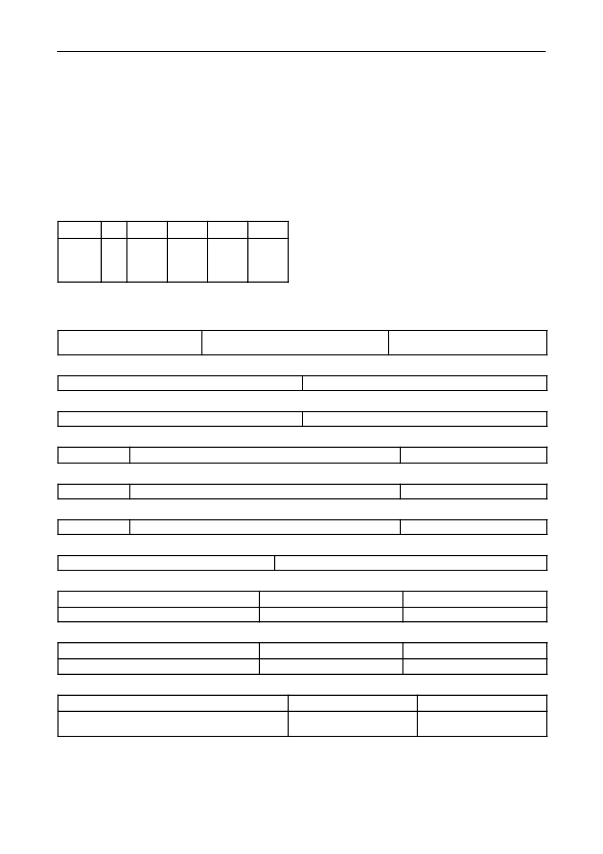
MODELTK 76 -- CALIBRATION DATA FOR BOSCH INJECTION PUMP
TYPE VE 4/11 F 1250 L 794 -- 99472104 / VE 4/11 F 1250 L 810 -- 500324959
ASSEMBLY DATA
CALIBRATION TEST CONDITIONS
Pump timing on engine: delivery start 9o
0.5o before
Test bench conforming to ISO 4008/1 .../2
TDC of cylinder 1 compression stroke.
Injectors conforming to ISO
7440--A61
--
Plunger pre--lift for timing on engine: 1 mm (0.0394
(1.688.901.027 with calibrated pad
0.5 mm --
in.) from BDC (with tools 291754 -- 291755).
0.0197 in.).
Cylinder No.1 delivery line union on pump: marked
Injector pressure setting 247 to 253 bar (3582 to
with letter A.
3669 psi).
ASSEMBLY DIMENSIONS
Fuel supply pressure:
SYMBOL
SVS
K
MS
ya
yb
0.35 + 0.05 bar (5.1 + 0.7 psi).
Delivery pipes (conforming to ISO 4093.2):
mm
--
3.1 to 3.5
0.9 to 1.3
36.5 to
38.8 to 44
(in.)
(0.1220 to
(0..0354 to
38.5
(1.5276 to
6x2x450mm(0.2362x0.0787x17.716in.).
0.1378)
0.0512)
(1.437 to
1.7323)
Graduate drain time
: 30î.
1.5157)
Test liquid: ISO 4113 at a temperature of 45o
1oC
(113o
33.8oF) at outlet.
1. START OF DELIVERY
Plunger pre--lift from TDC: mm --
Pump rotation (viewed from drive side):
Injection order:1--3--4--2
counter--clockwise
2. ADVANCE REGULATOR STROKE
rpm: 800
Advance stroke: 0.7 to 1.1 mm (0.0276 to 0.0433 in.)
3. FUEL SUPPLY PUMP PRESSURE
rpm: 800
Internal pressure: 5.9 to 6.5 bar (85.6 to 94.3 psi)
4. FULL LOAD DELIVERY
rpm: 800
Delivery per 1000 shots: 65.1 to 66.1cm3 (0.0143 to 0.0145 gal.)
Spread:-- 3.5 cm3 (-- 0.0008 gal.)
5. SPREAD GOVERNOR AT IDLE SPEED
rpm: 325
Delivery per 1000 shots: 7.5 to 8.5 cm3 (0.0016 to 0.0019 gal.)
Spread:
3.5 cm3 (0.0008 gal.)
6. SPREAD GOVERNOR AT MAXIMUM SPEED
rpm: 1270
Delivery per 1000 shots: 43.5 to 44.5 cm3 (0.0096 to 0.0098 gal.)
Spread: -- cm3
7. DELIVERY AT STARTING SPEED
rpm: 100
Delivery per 1000 shots: 75 to 105 cm3 (0.0165 to 0.0231 gal.)
8. TRANSFER PRESSURE PROGRESSION
rpm
800
400
Internal pressure
bar (psi)
5.9 to 6.5 (85.6 to 94.3 psi)
3.8 to 4.4 (55.1 to 63.8 psi)
9. INJECTION ADVANCE PROGRESSION
rpm
800
Advance stroke
mm (in.)
0.7 to 1.1 (0.0276 to 0.0433)
10. BACKFLOW
rpm
400
1200
Backflow
cm3 (gal.)
44.1 to 77.2 (0.0097 to 0.017)
60.7 to 104.8 (0.0134 to
0.0231)
(continued)
Note: the values shown above in brackets must be used for checking purposes only.
603.54.381.00 -- 05 -- 2001
SECTION 10 -- ENGINE -- CHAPTER 1
11
(continued)
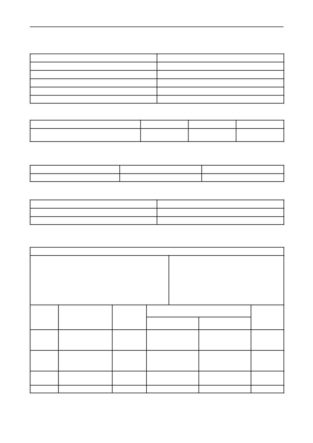
11. DELIVERY PROGRESSION
rpm
Delivery per 1000 shots: cm3 (gal.)
1340
0 to 3 (0 to 0.0007)
1270
43.5 to 44.5 (0.0096 to 0.0098)
1200
58.4 to 61.3 (0.0128 to 0.0135)
800
65.1 to 66.1 (0.0143 to 0.0145)
400
59.6 to 67.6 (0.0131 to 0.0149)
12. DELIVERY CHECK AT IDLE SPEED
rpm
325
290
370
Delivery per 1000 shots:
cm3 (gal.)
7.5 to 8.5
15.5 to 23.5
0 to 3
(0.0016 to 0.0019)
(0.00345 to 0.0052)
(0 to 0.0007)
Note: the values shown above in brackets must be used for checking purposes only.
13. ZERO CAPACITY (STOP)
rpm
Voltage (volts)
Delivery per 1000 shots: cm3 (gal.)
325
0
0 to 3 (0 to 0.0007)
14. AUTOMATIC START SUPPLEMENT
rpm
Delivery per 1000 shots: cm3 (gal.)
100
70 to 105 (0.0154 to 0.0231)
250
47.5 to 55.5 (0.0104 to 0.0122)
BENCH TEST PERFORMANCE DATA
TEST Conditions
Fixed advance before TDC cylinder No.1 in compression
Relative humidity 70o/o
5.
stroke: (see previous page)
Engine without fan, air filter and exhaust silencer.
Ambient temperature 25oC (77oF).
Atmospheric pressure 740
5 mm (29.1339
0.1968 in.)
Specific gravity of diesel fuel 840 g/l at a tem-
mercury.
perature of 15oC (59oF).
Fuel consum-
Engine speed
Power output with engine run--in for a total of:
Throttle
ption
lever
Braking load applied
Production speed
50 hours (total)
position
rpm
kW (Hp)
kW (Hp)
kg (lbs.)/h
11.8 to 12.4
For maximum power
51.1 to 54
Maximum
2500
50
(68)
(26.01 to
output
(69.5 to 73.4)
27.34)
8.0 to 8.4
36.8 to 39
Maximum
For maximum torque
1500
36
(48.9)
(17.66 to
(51.1 to 54.2)
18.52)
2700 to
Maximum
None (no--load)
--
--
--
2750
Minimum
None (no--load)
625 to 675
--
--
--
603.54.381.00 -- 05 -- 2001
12
SECTION 10 -- ENGINE -- CHAPTER 1
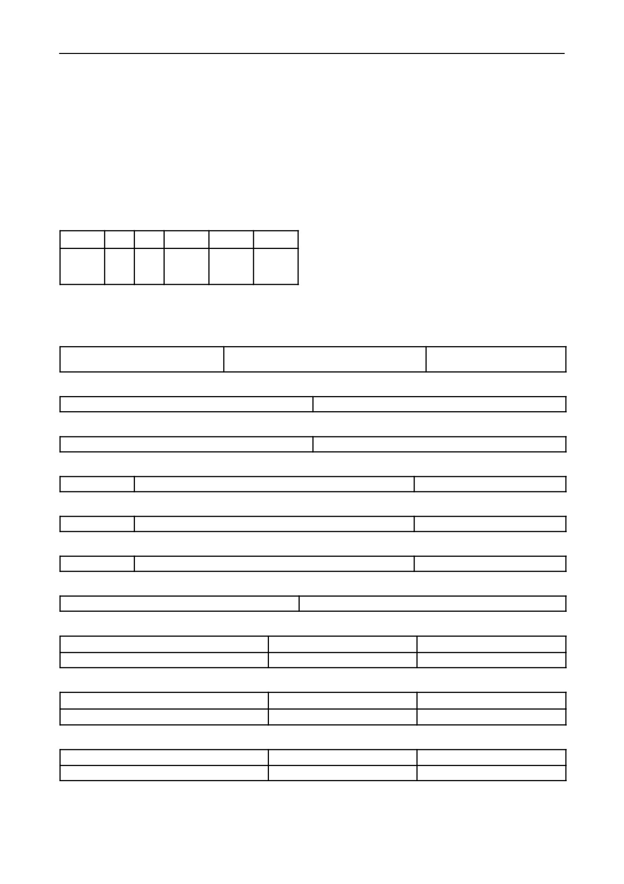
MODELTK 85 -- CALIBRATION DATA FOR BOSCH INJECTION PUMP
TYPE VE 4/11 F 1250 L 773 -- 99472102 / VE 4/11 F 1250 L 787 -- 500324962
ASSEMBLY DATA
CALIBRATION TEST CONDITIONS
Pump timing on engine: delivery start 9o
0.5o before
Test bench conforming to ISO 4008/1 .../2
TDC of cylinder 1 compression stroke.
Injectors conforming to ISO
7440--A61
--
Plunger pre--lift for timing on engine: 1 mm (0.0394
(1.688.901.027 with calibrated pad
0.5 mm --
in.) from BDC (with tools 291754 -- 291755).
0.0197 in.).
Cylinder No.1 delivery line union on pump: marked
with letter A.
Injector pressure setting 250 to 253 bar (3626 to
3669 psi).
ASSEMBLY DIMENSIONS
Fuel supply pressure:
0.35 + 0.05 bar (5.1 + 0.7 psi).
SYMBOL
K
KF
r
ya
yb
Delivery pipes (conforming to ISO 4093.2):
mm
--
--
30.1
36.5 to 38.5
37.4 to 42.6
6x2x450mm(0.2362x0.0787x17.716in.).
(in.)
(1.185)
(1.437 to
(1.4724 to
Graduate drain time
: 30î.
1.5157)
1.6772)
Test liquid: ISO 4113 at a temperature of 45o
1oC
(113o
33.8oF) at outlet.
1. START OF DELIVERY
Plunger pre--lift from TDC:
Pump rotation (viewed from drive side): coun-
Injection order:1--3--4--2
mm --
ter--clockwise
2. ADVANCE REGULATOR STROKE
rpm: 900
Advance stroke: 0.7 to 1.1 mm (0.0276 to 0.0433 in.)
3. FUEL SUPPLY PUMP PRESSURE
rpm: 900
Internal pressure: 6.7 to 7.3 bar (97.2 to 105.9 psi)
4. FULL LOAD DELIVERY
rpm: 800
Delivery per 1000 shots: 61.2 to 62.2 cm3 (0.0135 to 0.0137 gal.)
Spread:
3.5 cm3 (0.0008 gal.)
5. SPREAD GOVERNOR AT IDLE SPEED
rpm: 300
Delivery per 1000 shots: 9.2 to 10.2 cm3 (0.002 to 0.0022 gal.)
Spread:
-- cm3
6. SPREAD GOVERNOR AT MAXIMUM SPEED
rpm: 1300
Delivery per 1000 shots: 41.1 to 42.1 cm3 (0.0090 to 0.0092 gal.)
Spread:
3.5 cm3 (0.0008 gal.)
7. DELIVERY AT STARTING SPEED
rpm: 100
Delivery per 1000 shots: 33 to 73 cm3 (0.0073 to 0.0161 gal.)
8. TRANSFER PRESSURE PROGRESSION
rpm
900
450
Internal pressure supply:
bar (psi)
6.7 to 7.3 (97.2 to 105.9 psi)
4.3 to 5.3 (62.4 to 76.9 psi)
9. INJECTION ADVANCE PROGRESSION
rpm
900
1020
Advance stroke
mm (in.)
0.7 to 1.1 mm (0.0276 to 0.0433)
1.3 to 1.9 (0.0512 to 0.0748)
10. BACKFLOW
rpm
450
1250
Backflow for 10 s
cm3 (gal.)
18 to 30 (0.0040 to 0.0066)
24 to 40 (0.0053 to 0.0088)
(continued)
Note: the values shown above in brackets must be used for checking purposes only.
603.54.381.00 -- 05 -- 2001
SECTION 10 -- ENGINE -- CHAPTER 1
13
(continued)
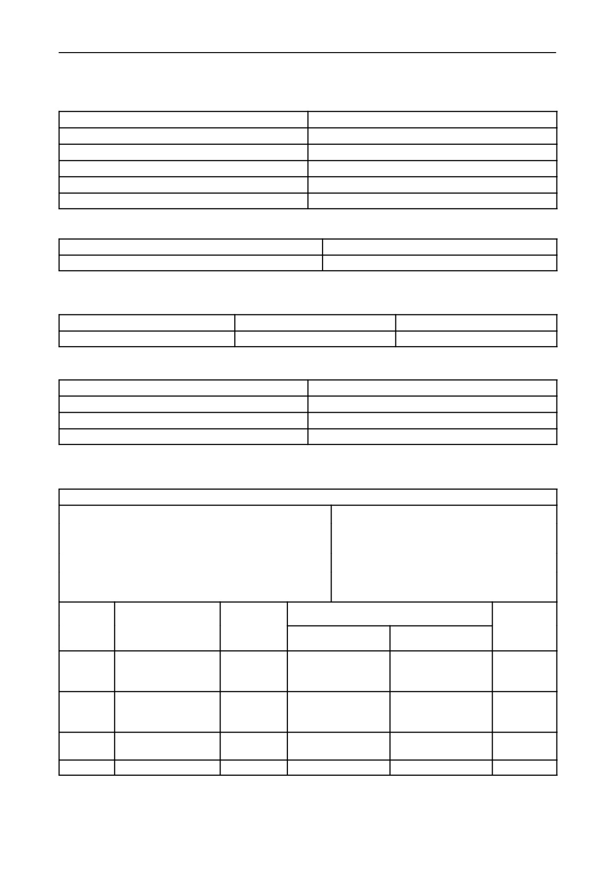
11. DELIVERY PROGRESSION
rpm
Delivery per 1000 shots: cm3 (gal.)
1400
0 to 3 (0 to 0.0007)
1300
41.1 to 42.1 (0.0090 to 0.0092)
1250
52.5 to 57.5 (0.0115 to 0.0126)
1200
53.5 to 58.5 (0.0118 to 0.0129)
800
61.2 to 62.2 (0.0135 to 0.0137)
12. DELIVERY CHECK AT IDLE SPEED
rpm
300
Delivery per 1000 shots:
cm3 (gal.)
9.2 to 10.2 (0.0020 to 0.0022)
Note: the values shown above in brackets must be used for checking purposes only.
13. ZERO CAPACITY (STOP)
rpm
Voltage (volts)
Delivery per 1000 shots: cm3
(gal.)
300
0
0 to 3 (0 to 0.0007)
14. AUTOMATIC START SUPPLEMENT
rpm
Delivery per 1000 shots: cm3 (gal.)
100
33 to 73 (0.0073 to 0.0161)
250
34 to 44 (0.0075 to 0.0097)
140
40 to 70 (0.0088 to 0.0154)
BENCH TEST PERFORMANCE DATA
Test conditions
Fixed advance before TDC cylinder No.1 in compression
Relative humidity 70o/o
5.
stroke: (see previous page)
Engine without fan, air filter and exhaust silencer.
Ambient temperature 25oC (77oF).
Atmospheric pressure 740
5 mm (29.1339
0.1968 in.)
Specific gravity of diesel fuel 840 g/l at a tem-
mercury.
perature of 15oC (59oF).
Fuel consum-
Engine speed
Power output with engine run--in for a total of:
Throttle
ption
lever
Braking load applied
Production speed
50 hours (total)
position
rpm
kW (Hp)
kW (Hp)
kg (lbs.)/h
12.9 to 13.7
For maximum power
56.2 to 59.6
Maximum
2500
55
(74.8)
(28.44 to
output
(76.4 to 81)
30.2)
8.8 to 9.4
40.2 to 42.7
Maximum
For maximum torque
1500
39.3
(53.4)
(19.4 to
(54.7 to 58.1)
20.72)
2700 to
Maximum
None (no--load)
--
--
--
2750
Minimum
None (no--load)
625 to 675
--
--
--
603.54.381.00 -- 05 -- 2001
14
SECTION 10 -- ENGINE -- CHAPTER 1
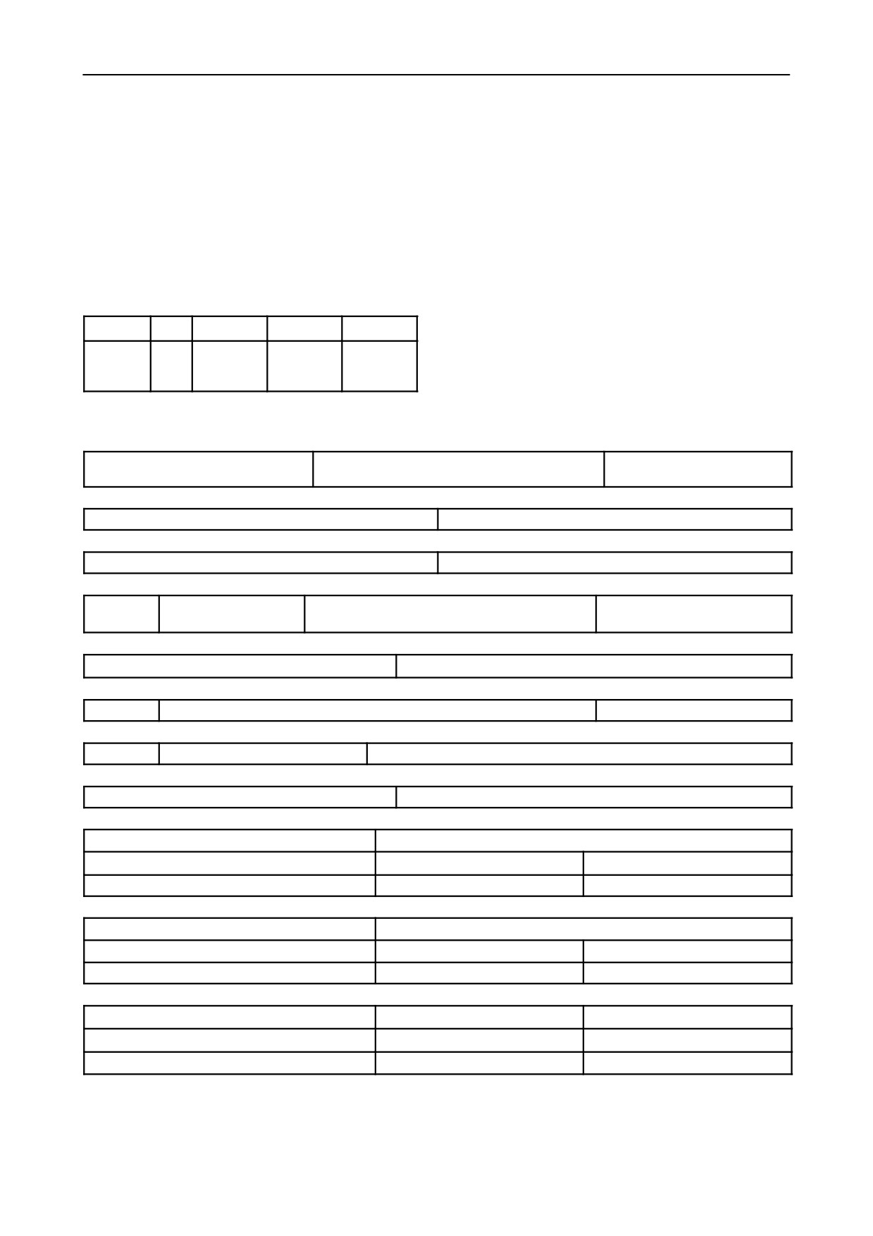
MODELTK 95 -- CALIBRATION DATA FOR BOSCH INJECTION PUMP
TYPE VE 4/11 F 1250 L 850 -- 500358111
ASSEMBLY DATA
CALIBRATION TEST CONDITIONS
Pump timing on engine: delivery start 5o
0.5o before
Test bench conforming to ISO 4008/1 .../2
TDC of cylinder 1 compression stroke.
Injectors conforming to ISO
7440--A61
--
Plunger pre--lift for timing on engine: 1 mm (0.0394
(1.688.901.027 with calibrated pad
0.5 mm --
in.) from BDC (with tools 291754 -- 291755).
0.0197 in.).
Cylinder No.1 delivery line union on pump: marked
Injector pressure setting 250 to 253 bar (3626 to
with letter A.
3669 psi).
ASSEMBLY DIMENSIONS
Fuel supply pressure:
0.35 + 0.05 bar (5.1 + 0.7 psi).
SYMBOL
K
r
ya
yb
Delivery pipes (conforming to ISO 4093.2):
mm
--
30.1
36.5 to 38.5
40 to 46
6x2x450mm(0.2362x0.0787x17.716in.).
(in.)
(1.185)
(1.437 to
1.5157)
Graduate drain time
: 30î.
Test liquid: ISO 4113 at a temperature of 45o
1oC
(113o
33.8oF) at outlet.
1. START OF DELIVERY
Plunger pre--lift from TDC: mm --
Pump rotation (viewed from drive side): coun-
Injection order:1--3--4--2
ter--clockwise
2. ADVANCE REGULATOR STROKE
rpm: 900
Advance stroke: 0.8 to 1.2 mm (0.0315 to 0.0472 in.)
3. FUEL SUPPLY PUMP PRESSURE
rpm: 900
Internal pressure: 6.2 to 6.8 bar (89.9 to 98.6 psi)
4. FULL--LOAD DELIVERY WITH BOOSTER PRESSURE
rpm: 750
LDA pressure: kPa 100
Delivery per 1000 shots: 76 to 77 cm3 (0.0167
Spread:
3.5 cm3 (0.0008 gal.)
to 0.0169 gal.)
5. FULL--LOAD DELIVERY WITHOUT BOOSTER PRESSURE
rpm: 600
Delivery per 1000 shots: 54.2 to 55.2 cm3 (0.0119 to 0.0121 gal.)
6. SPREAD GOVERNOR AT IDLE SPEED
rpm: 325
Delivery per 1000 shots: 11.5 to 12.5 cm3 (0.0025 to 0.0027 gal.)
Spread:
4.0 cm3 (0.0009 gal.)
7. SPREAD GOVERNOR AT MAXIMUM SPEED
rpm: 1300
LDA pressure: kPa 100
Delivery per 1000 shots: 42.7 to 43.7 cm3 (0.0094 to 0.0096 gal.)
8. DELIVERY AT STARTING SPEED
rpm: 100
Delivery per 1000 shots: 85 to 125 cm3 (0.0187 to 0.0275 gal.)
9. TRANSFER PRESSURE PROGRESSION
LDA pressure:
kPa
100
rpm
400
900
Internal pressure supply:
bar (psi)
2.9 to 3.9 (42.1 to 56.6)
6.2 to 6.8 (89.9 to 98.6)
10. INJECTION ADVANCE PROGRESSION
LDA pressure
kPa
100
rpm
900
1050
Advance stroke
mm (in.)
0.8 to 1.2 (0.0315 to 0.0472)
1.4 to 2.0 (0.0551 to 0.0787)
11. BACKFLOW
rpm
600
1250
LDA pressure
kPa
0
100
Backflow
cm3 (gal.)
18 to 30 (0.0039 to 0.0066)
22 to 38 (0.0048 to 0.0083)
(continued)
Note: the values shown above in brackets must be used for checking purposes only.
603.54.381.00 -- 05 -- 2001
SECTION 10 -- ENGINE -- CHAPTER 1
15
(continued)
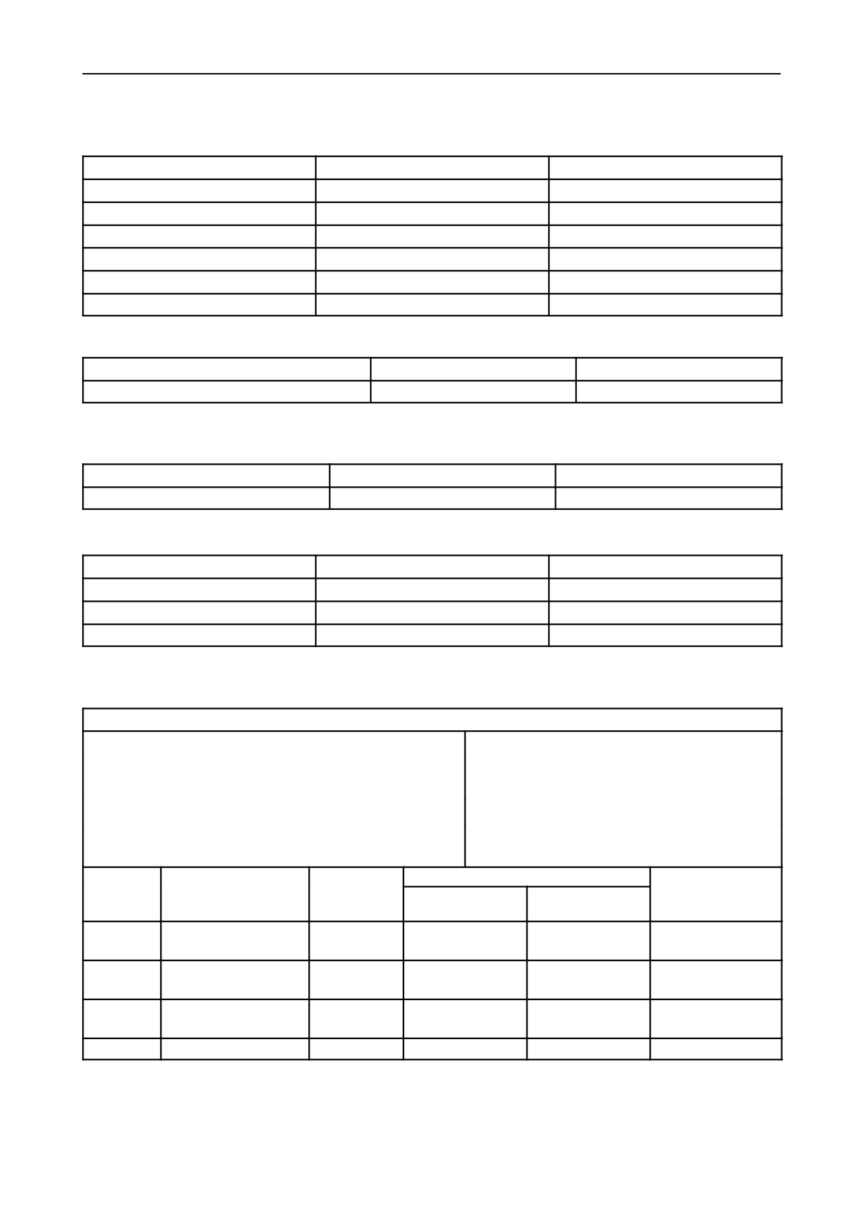
12. DELIVERY PROGRESSION
rpm
Pressure LDA kPa
Delivery per 1000 shots: cm3 (gal.)
600
25
70.5 to 71.5 (0.0155 to 0.0157)
1380
100
0 to 3 (0 to 0.0007)
1300
100
42.7 to 43.7 (0.0094 to 0.0096)
1250
100
66.1 to 70.1 (0.0145 to 0.0154)
750
100
76 to 77 (0.0167 to 0.0169)
600
0
54.2 to 55.2 (0.0119 to 0.0121)
13. DELIVERY CHECK AT IDLE SPEED
rpm
325
275
Delivery per 1000 shots
cm3 (gal.)
11.5 to 12.5 (0.0025 to 0.0027)
28.4 to 40.4 (0.0062 to 0.0089)
Note: the values shown above in brackets must be used for checking purposes only.
14. ZERO CAPACITY (STOP)
rpm
Voltage (volts)
Delivery per 1000 shots: cm3 (gal.)
325
0
0 to 3 (0 to 0.0007)
15. AUTOMATIC START SUPPLEMENT
rpm
Pressure LDA kPa
Delivery per 1000 shots: cm3 (gal.)
100
--
85 to 125 (0.0187 to 0.0275)
250
--
60 to 70 (0.0132 to 0.0154)
150
--
100 to 130 (0.0220 to 0.0286)
BENCH TEST PERFORMANCE DATA
Test conditions
Fixed advance before TDC cylinder No.1 in compression
Relative humidity 70o/o
5.
stroke: (see previous page)
Engine without fan, air filter and exhaust silencer.
Ambient temperature 25oC (77oF).
Atmospheric pressure 740
5 mm (29.1339
0.1968 in.)
Specific gravity of diesel fuel 840 g/l at a tem-
mercury.
perature of 15oC (59oF).
Engine speed
Power output with engine run--in for a total of:
Fuel consumption
Throttle
lever
Braking load applied
Production speed
50 hours (total)
position
rpm
kW (Hp)
kW (Hp)
kg (lbs.)/h
For maximum power
64.5 to 68.5
15.2 to 16.2
Maximum
2500
63.2
(85.9)
output
(87.7 to 93.1)
(33.51 to 35.71)
50.5 to 53.5
10.8 to 11.4
Maximum
For maximum torque
1500
49.5
(67.3)
(68.7 to 72.8)
(23.81 to 25.13)
2700 to
Maximum
None (no--load)
--
--
--
2750
Minimum
None (no--load)
625 to 675
--
--
--
603.54.381.00 -- 05 -- 2001
16
SECTION 10 -- ENGINE -- CHAPTER 1
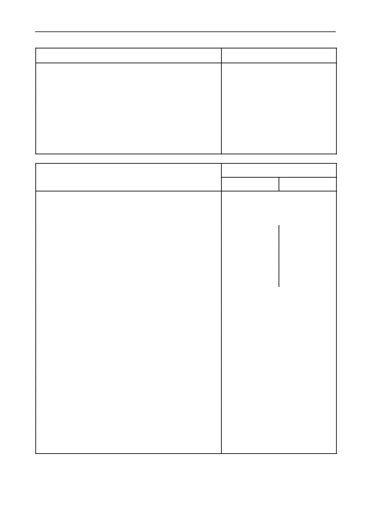
FUEL SUPPLY PUMP DATA
mm (in.)
Eccentricity of drive shaft
3
(0.1181)
Diameter of drive shaft at bushings
31.975 to 32.000 (1.2588 to 1.2598)
Internal diameter of installed and reamed bushings
32.050 to 32.075 (1.2618 to 1.2628)
Interference between bushings and seats
0.063 to 0.140 (0.0025 to 0.0055)
Clearance between axle shafts and bushes
0.050 to 0.100 (0.0020 to 0.0039)
Thickness of internal washer
1.45 to 1.50 (0.0571 to 0.0591)
Thickness of external washer
2.93 to 3.00 (0.1154 to 0.1181)
mm (in.)
CRANKCASE/CYLINDER BLOCK DATA
Bore 100
Bore 104
Cylinder block
cast--iron monobloc with replaceable
dry--fitted cylinder liners, incorporating
seatings for crankshaft bearings, cam-
shaft and tappet assemblies
Internal diameter of cylinder liners
100 to 100.024 (1)
104 to 104.024 (1)
(3.937 to 3.9379)
(4.0945 to 4.0954)
External diameter of cylinder liners
103.02 to 103.05
107.02 to 107.05
(4.0559 to 4.0571)
(4.2134 to 4.2146)
Diameter of cylinder liner bores on block
102.85 to 102.9
106.85 to 106.9
(4.0492 to 4.0512)
(4.2067 to 4.2087)
Interference fit between cylinder liners and bores on the cylinder
block
0.120 to 0.200 (0.0047 to 0.0079)
Cylinder liners internal diameter oversizes
0.4 to 0.8 (0.0157 to 0.0315)
Liner external diameter oversizes
0.2
(0.0079)
Maximum permissible liner ovality or taper due to wear (2)
0.12
(0.0047)
Main journal half bearing seat diameter
84.200 to 84.230 (3.3150 to 3.3161)
Camshaft bushing seat diameter:
-- front
54.780 to 54.805 (2.1567 to 2.1577)
-- intermediate
54.280 to 54.305 (2.1370 to 2.1380)
-- rear
53.780 to 53.805 (2.1173 to 2.1183)
Diameter of standard tappet bores in crankcase
15.000 to 15.018 (0.5905 to 0.5912)
Tappet oversizes
0.1 -- 0.2 -- 0.3
(0.0039 -- 0.0079 -- 0.0118)
(1) Measured after press--fitting and reaming.
(2) Measure in the area swept by piston rings, both parallel and perpendicular to the crankshaft axis.
603.54.381.00 -- 05 -- 2001
SECTION 10 -- ENGINE -- CHAPTER 1
17
mm (in.)
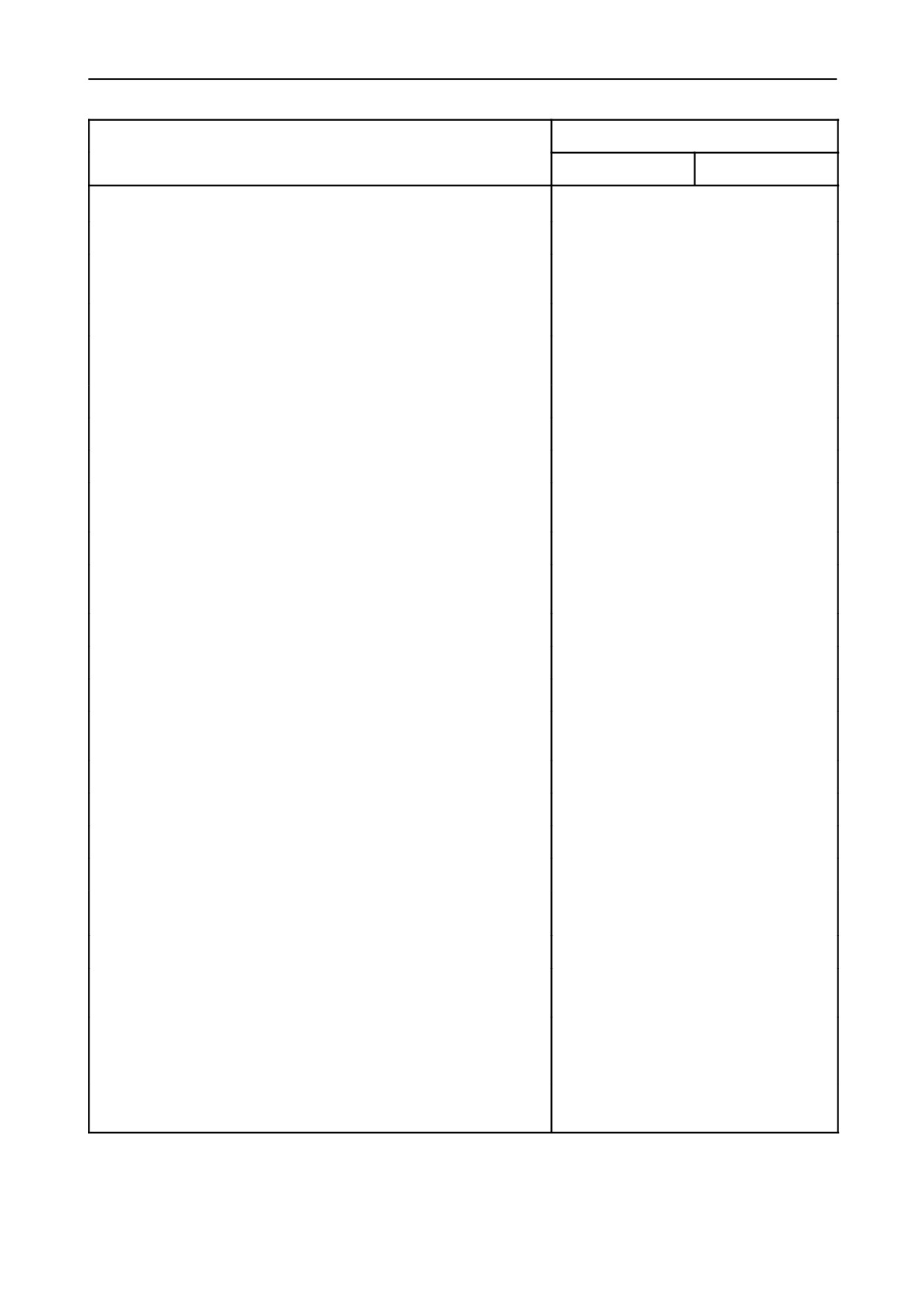
CRANKSHAFT AND BEARINGS DATA
Bore 100
Bore 104
Crankshaft
balanced with integral counterweights
Standard journal diameter
79.791 to 79.810 (1) (3.1414 to 3.1421)
Journal undersizes
0.254 -- 0.508 -- 0.762 -- 1.016
(0.01 -- 0.02 -- 0.03 -- 0.04)
Main journal half bearing thickness
2.168 to 2.178 (0.0853 to 0.0857)
Main half bearing undersizes (internal diameter)
0.254 -- 0.508 -- 0.762 -- 1.016
(0.01 -- 0.02 -- 0.03 -- 0.04)
Bearing shell to journal clearance
0.034 to 0.103 (0.0013 to 0.0040)
Maximum permitted wear clearance
0.180
(0.0071)
Standard crankpin diameter
63.725 to 63.744 (1) (2.5086 to 2.5096)
Crankpin undersizes
0.254 -- 0.508 -- 0.762 -- 1.016
(0.01 -- 0.02 -- 0.03 -- 0.04)
Standard connecting rod half bearing thickness
1.805 to 1.815 (0.0711 to 0.0714)
Connecting rod half bearing undersizes (internal diameter)
0.254 -- 0.508 -- 0.762 -- 1.016
(0.01 -- 0.02 -- 0.03 -- 0.04)
Bearing to crankpin clearance
0.033 to 0.087 (0.0013 to 0.0034)
Maximum permitted wear clearance
0.180
(0.0071)
Standard crankshaft thrust washer thickness
3.378 to 3.429 (0.1330 to 0.135)
Thrust washer oversizes (thickness)
0.127 -- 0.254 -- 0.381 -- 0.508
(0.005 -- 0.01 -- 0.015 -- 0.02)
Width of main bearing including thrust washers
31.766 to 31.918 (1.2506 to 1.2566)
Width of corresponding crankshaft journal
32.000 to 32.100 (1.2598 to 1.2602)
Crankshaft assembly endfloat
0.082 to 0.334 (0.0032 to 0.0131)
Maximum permitted axial wear clearance
0.40
(0.0157)
Maximum ovality or taper of journals and crankpin after regrind-
ing
0.01
(0.0039)
Maximum ovality or taper of journals and crankpin
0.05
(0.0020)
Maximum tolerance for alignment of crankshaft journals with
crankshaft supported on the two outer journals
0.1
(0.0039)
Maximum permitted tolerance, in both directions, on crankpin
alignment (3--cylinder engine), or of each pair of crankpins rela-
tive to crankshaft journals (4--cylinder engine)
0.25
(0.0098)
Maximum tolerance for run--out between the outer surfaces of
the crankshaft journals and the crankshaft centreline
0.1
(0.0039)
(continued)
(1) Crankshafts with 0.1 mm (0.0039 in.) undersize journals, crankpins and, consequently, undersize bearing shells may
be fitted in factory production.
603.54.381.00 -- 05 -- 2001
18
SECTION 10 -- ENGINE -- CHAPTER 1
(continued)
mm (in.)
CRANKSHAFT AND BEARINGS DATA
Bore 100
Bore 104
Maximum permitted tolerance on run--out of flywheel mounting
flange surface relative to the crankshaft centreline, measured with
1/100 mm scale dial gauge resting on front flange surface (A,
fig. 96) on a 108 mm (4.252 in.) diameter (total dial gauge reading)
0.025
(0.001)
Maximum permitted tolerance on co--axial alignment of flywheel
centering (B, fig. 96 ) in relation to crankshaft journals (total dial
gauge reading)
0.04
(0.0016)
mm (in.)
CONNECTING ROD DATA
Bore 100
Bore 104
Connecting rods
cast--iron with oil way
Diameter of small end bushing seat
41.846 to 41.884 (1.6475 to 1.649)
Outside diameter of small end bushing
41.979 to 42.017 (1.6527 to 1.6542)
Interference between small end bushing and seat
0.095 to 0.171 (0.0037 to 0.0067)
Inside diameter of small end bushing (measured after fitting) . . .
38.004 to 38.014 (1.4962 to 1.4966)
Diameter of big end bearing seats
67.407 to 67.422 (2.6538 to 2.6544)
Max. tolerance for parallelism between the small end and the big
end axes measured at 125 mm (4.9213 in.)
0.07
(0.0027)
Maximum weight difference between con rods in same engine . .
25 g. (0.055 lbs.)
603.54.381.00 -- 05 -- 2001
SECTION 10 -- ENGINE -- CHAPTER 1
19
mm (in.)
PISTON DATA
Bore 100
Bore 104
Pistons
light alloy with three compression rings,
including two seal rings and one
scraper ring
Standard piston diameter, measured at 57 mm from skirt base
and perpendicularly to the gudgeon pin axis
99.827 to 99.841
103.812 to
(3.9302 to 3.9307)
103.826
(4.0871 to 4.0876)
Piston clearance in cylinder liner
0.159 to 0.197
0.174 to 0.212
(0.0062 to 0.0077)
(0.0068 to 0.0083)
Maximum permitted wear clearance
0.30
(0.0118)
Piston oversizes
0.4 -- 0.8 (0.0157 -- 0.0315)
Piston protrusion at TDC from cylinder block face
0.355 to 0.761 (0.014 to 0.03)
Gudgeon pin diameter
37.983 to 37.990 (1.4954 to 1.4957)
Diameter of gudgeon pin seat in piston
37.993 to 38.000 (1.4958 to 1.4961)
Gudgeon pin to seat clearance
0.003 to 0.017 (0.0001 to 0.0007)
Gudgeon pin to small end bearing clearance
0.014 to 0.031 (0.0005 to 0.0012)
Maximum permitted wear clearance
0.06
(0.0024)
Maximum weight difference between pistons in same engine . . .
20 g. (0.0001 lbs.)
Piston ring groove clearance (measured vertically):
-- 1st ring
0.090 to 0.122 (0.0035 to 0.0048)
-- 2nd ring
0.060 to 0.092 (0.0024 to 0.0036)
-- 3rd ring
0.040 to 0.075 (0.0016 to 0.0029)
Maximum permitted wear clearance:
-- 1st ring
0.50
(0.0197)
-- 2nd and 3rd ring
0.20
(0.0079)
Assembly clearance between piston ring ends in cylinder
sleeves:
-- 1st ring
0.35 to 0.55
0.40 to 0.65
(0.0138 to 0.0216)
(0.0157 to 0.0256)
-- 2nd ring
0.30 to 0.45
0.30 to 0.55
(0.0118 to 0.0177)
(0.0118 to 0.0216)
-- 3rd ring
0.30 to 0.60 (0.0118 to 0.0024)
Maximum permissible gap (wear limit)
1.20
(0.0472)
603.54.381.00 -- 05 -- 2001
20
SECTION 10 -- ENGINE -- CHAPTER 1
mm (in.)
VALVE TIMING GEAR DATA
Bore 100
Bore 104
Clearance between sides of timing gear pair teeth
0.160
(0.0063)
Inside diameter of intermediate gear bushings (fitted and
reamed)
37.050 to 37.075 (1.4587 to 1.4596)
Diameter of intermediate gear journal
36.975 to 37.000 (1.4557 to 1.4567)
Clearance between pin and relative bushings
0.050 to 0.100 (0.002 to 0.0039)
Maximum permitted wear clearance
0.15
(0.0059)
Bushing interference fit in seat in intermediate gear
0.063 to 0.140 (0.0025 to 0.0055)
Outside diameter of camshaft bearings:
-- front
54.875 to 54.930 (2.1604 to 2.1626)
-- intermediate
54.375 to 54.430 (2.1407 to 2.1429)
-- rear
53.875 to 53.930 (2.1211 to 2.1232)
Interference between bearings and seats in cylinder block
0.070 to 0.150 (0.0027 to 0.0059)
Inside diameter of camshaft bearings (fitted and reamed):
-- front
51.080 to 51.130 (2.011 to 2.013)
-- intermediate
50.580 to 50.630 (1.9913 to 1.9933)
-- rear
50.080 to 50.130 (1.9716 to 1.9736)
Diameter of camshaft journals:
-- front
50.970 to 51.000 (2.0067 to 2.0079)
-- intermediate
50.470 to 50.500 (1.9870 to 1.9882)
-- rear
49.970 to 50.000 (1.9673 to 1.9685)
Clearance between camshaft journals and bushings
0.080 to 0.160 (0.0031 to 0.0063)
Maximum permitted wear clearance
0.20
(0.0079)
Camshaft endfloat between thrust plate and seat on camshaft . .
0.070 to 0.220 (0.0027 to 0.0087)
For further timing system technical data
see page 4
mm (in.)
TAPPET DATA
Bore 100
Bore 104
Tappet bore in crankcase
15.000 to 15.018 (0.5905 to 0.5912)
Outside diameter of standard tappet
14.950 to 14.970 (0.5886 to 0.5894)
Tappet running clearance
0.030 to 0.068 (0.0012 to 0.0027)
Maximum permitted wear clearance
0.15
(0.0059)
Tappet oversizes
0.1 -- 0.2 -- 0.3
(0.0039 -- 0.0079 -- 0.0118)
603.54.381.00 -- 05 -- 2001
SECTION 10 -- ENGINE -- CHAPTER 1
21
mm (in.)
ROCKER ARM - VALVE DATA
Bore 100
Bore 104
Diameter of shaft bores in rocker arms
18.016 to 18.034 (0.7093 to 0.71)
Diameter of rocker arm shaft
17.982 to 18.000 (0.7079 to 0.7087)
Rocker shaft to rocker arm bore clearance
0.016 to 0.052 (0.0006 to 0.002)
Maximum permitted wear endfloat
0.15
(0.0059)
Rocker arm spacing springs:
-- free length
59.5
(2.3425)
-- length under load of 46 to 52 N
44
(1.7323)
(4.7 to 5.3 kg, 10.36 to 11.68 lbs.)
Valve clearance for timing check
0.45
(0.0177)
Valve clearance for normal running (engine cold):
-- inlet valve
0.30
0.05
(0.0118
0.002)
-- exhaust valve
0.30
0.05
(0.0118
0.002)
Cam lift:
-- inlet valve
5.67
(0.2232)
-- exhaust valve
5.95
(0.2342)
(*) Only fitted on
MAIN DATA FOR EQUALIZER
4--cylinder models
WITH COUNTER ROTATION MASSES (fig. 60) (*)
mm (in.)
Bushing (28) interference fit in seat on gear unit (26)
0.063 to 0.140 (0.0025 to 0.0055)
Clearance between intermediate gear journal (27) and bushing
(28)
0.050 to 0.100 (0.002 to 0.0039)
Interference between bushings and support seats (20)
0.063 to 0.140 (0.0025 to 0.0055)
Clearance between gear unit shaft (22) and relative bushings . .
0.050 to 0.100 (0.002 to 0.0039)
Clearance between sides of sleeve grooves (17), drive gear unit
connection (22) and rotating masses gear unit (13)
0.038 to 0.106 (0.0015 to 0.0042)
Interference between front bush (16) and seat on casing (12) . .
0.063 to 0.140 (0.0025 to 0.0055)
Clearance between rotating masses shaft (13) and front bush
(16)
0.050 to 0.100 (0.002 to 0.0039)
Interference between rotating masses rear bush (13) and seat on
support (7)
0.037 to 0.101 (0.0014 to 0.0040)
Clearance between shaft (13) and rear bush
0.013 to 0.061 (0.0005 to 0.0024)
Interference between bushings and relative seats on masses (6)
0.040 to 0.100 (0.0016 to 0.0039)
Clearance between rotating masses axis (5) and relative
bushings
0.020 to 0.073 (0.0008 to 0.0029)
Interference between intermediate gear bush (10) and relative
seat on rotating masses casing (12)
0.037 to 0.101 (0.0014 to 0.00409)
Clearance between intermediate gear shaft (10) and relative
0.013 to 0.061 (0.0005 to 0.0024)
bush
Clearance between the teeth and the coupled wheels
0.080
(0.0031)
603.54.381.00 -- 05 -- 2001
22
SECTION 10 -- ENGINE -- CHAPTER 1
mm (in.)
CYLINDER HEAD DATA
Bore 100
Bore 104
Cylinder head
with valve seats cut directly in the
casting and press--fitted steel valve
guides.
Original height of cylinder head
92
(3.622)
Maximum face re--grinding depth that can be removed from the
cylinder head in the event of reboring
0.5
(0.0197)
Diameter of standard valve guide bores in head
13.950 to 13.983 (0.5492 to 0.5505)
Outside diameter of standard valve guides
13.993 to 14.016 (0.5509 to 0.5518)
Guide interference fit in bores
0.010 to 0.066 (0.0004 to 0.0026)
Inside diameter of valve guide (fitted in head)
8.023 to 8.043 (0.3159 to 0.3166)
Valve stem diameter
7.985 to 8.000 (0.3144 to 0.315)
Assembly clearance between valve stem and guide
0.023 to 0.058 (0.0009 to 0.0023)
Maximum permitted wear endfloat
0.13
(0.0005)
Maximum run--out of valve guided on its stem measured through
360o with dial gauge contact point resting on valve head contact
band
0.03
(0.0012)
Valve guide oversizes
0.2
(0.0079)
Valve seat angle in head:
-- inlet valve
60o
5í
-- exhaust valve
45o
5í
Valve face angle:
-- inlet valve
60o 30í
7í
-- exhaust valve
45o 30í
7í
Valve head diameter:
-- inlet valve
45.300 to 45.500 (1.7835 to 1.7913)
-- exhaust valve
37.500 to 37.750 (1.4764 to 1.4862)
Valve stand--in relative to cylinder head face
0.7 to 1.0 (0.0275 to 0.0394)
Maximum permissible valve stand--in
1.3
(0.0512)
Inlet and exhaust valve springs:
-- free length
44.6
(1.7559)
-- length with valve closed, under load of 256 to 284 N
(26.1 to 28.9 kg, 57.54 to 63.71 lbs.)
34
(1.3386)
-- length with valve open, under load of
502 to 554 N
(51.2 to 56.5 kg, 112.88 to 124.56 lbs.)
23.8
(0.937)
Injector protrusion relative to head face:
D BOSCH injector no. 500307714 and 500317389
0.3 to 1.1 (0.0118 to 0.0433)
603.54.381.00 -- 05 -- 2001
SECTION 10 -- ENGINE -- CHAPTER 1
23
mm (in.)
LUBRICATION SYSTEM DATA
TK 65, TK 76,
TK 75, TK 95
TK 85
Assembly clearance between oil pump drive shaft and bush
0.016 to 0.055
--
(0.0006 to 0.0022)
Clearance between shaft and driven gear
0.033 to 0.066
--
(0.0013 to 0.0026)
Tooth backlash between drive and driven gears
0.100
(0.0039)
--
Radial clearance between drive and driven gears and housing . .
0.060 to 0.170
--
(0.0024 to 0.0067)
Thickness of drive and driven gears
40.961 to 41.000
--
(1.6126 to 1.6142)
Height of gear seat in pump
41.025 to 41.087
--
(1.6151 to 1.6176)
Endfloat between gears and gear housing in pump
0.025 to 0.126
--
(0.001 to 0.005)
Pressure relief valve spring
--
--
spring free length
45
(1.7716)
35.9
(1.2165)
--
length under load of 45 to 49 N (4.6 to 5 kg, 10.14 to 11.02 lbs.)
37.5
(1.4764)
--
--
length under load of 88 to 94 N (9 to 9.6 kg, 19.84 to 21.16 lbs.)
30.5
(1.2008)
--
--
spring length (2, fig. 134) under load of 127.8 to 141.2 N
(130 to 144 kg, 286.6 to 317.46 lbs.)
--
29
(1.1417)
--
spring length (2, fig. 134) under load of 233.4 to 258 N
(238 to 263 kg, 524.7 to 579.8 lbs.)
--
23.2
(0.9134)
For further lubrication technical data
see page 3
--
mm (in.)
COOLING SYSTEM DATA
Bore 100
Bore 104
Interference fit between pump impeller and shaft
0.017 to 0.059 (0.0007 to 0.0023)
Interference fit between fan hub and shaft
0.024 to 0.058 (0.0009 to 0.0023)
Interference fit between front seal bushing and impeller
0.012 to 0.058 (0.0005 to 0.0023)
For further cooling system technical data
see page 3
603.54.381.00 -- 05 -- 2001
24
SECTION 10 -- ENGINE -- CHAPTER 1
TORQUE SETTINGS WITH ANGLE
Tightening torque
PARTS TO TIGHTEN
Thread
Angle
Nm
kgm
Cylinder head bolts (2, fig. 3 , or fig. 5 )
M 12 x 1.25
70
7.1
90o + 90o
Main bearing cap bolts (4)
M 14 x 1.5
80
8.2
90o
Big--end cap bolts (5)
M 11 x 1.5
40
4.1
60o
Flywheel mounting bolts (3)
M 12 x 1.25
40
4.1
60o
TORQUE SETTINGS
Tightening torque
PARTS TO TIGHTEN
Thread
Nm
kgm
Rocker shaft pedestal bolts (1, fig. 3 , or fig. 5 )
M8
25
2.5
Crankshaft hub retaining nut (7)
M 30 x 1.5
294
30
Fan and alternator pulley bolts (6)
M
10 x 1.25
55
5.6
Additional rotating masses retaining bolts (1, fig. 6)
for models TK 76, TK 85 and TK 95
M
12 x 1.25
110
11.2
Intake manifold retaining bolts (1, fig. 23)
M8
25
2.6
Alternator and belt tension adjustment nut (2, fig. 22)
M
10 x 1.25
55
5.6
Coolant pump retaining bolts (1, fig. 27)
M
10 x 1.25
55
5.6
Nuts for injector mounting studs (1. fig. 90)
M8
25
(*)
2.6
(*)
Tappet cover nuts (1, fig. 32)
M8
15
1.5
Rocker shaft pedestal bolts (2, fig. 33)
M8
25
2.5
Oil pump and cover retaining bolts (1, fig. 41)
M8
25
2.6
Timing gear case and cover bolts (1, fig. 45)
M8
25
2.6
Intermediate flanged journal bolts (1, fig. 48)
M
10 x 1.25
55
5.6
Camshaft thrust plate retaining bolts (2, fig. 49)
M8
35
3.6
Rear crankcase cover bolts (2, fig. 69)
M8
25
2.6
Tappet adjuster locknuts (1, fig. 89)
M8
22
2.2
Exhaust manifold retaining bolts (2, fig. 21)
M8
25
2.6
Injection pump retaining bolts (1, fig. 191)
M8
25
2.6
Engine sump retaining bolts (4, fig. 38)
M
12 x 1.25
69
7
(*) Tighten the nuts in two stages -- see operations described in fig. 95.
603.54.381.00 -- 05 -- 2001
SECTION 10 -- ENGINE -- CHAPTER 1
25
TOOLS
X
294027
Twist bit for enlarging valve guide
bore.
Warning -- The operations described in this section
can only be carried out with ESSENTIAL tools indi-
X
294028
80 Tapered grinder for swaging ex-
cated by an (X).
haust valve guides.
To work safely and efficiently and obtain the best re-
sults, it is also necessary to use the recommended
X
293231
Bush for valve guide installation (with
specific tools listed below and certain other tools,
291046).
which are to be made according to the drawings in-
cluded in this manual.
X
291177
Engine valve guide reamer.
X
291050
Engine valve spring disassembly--as-
List of specific tools required for the various
sembly compressor.
operations described in this section.
X
293270
Set of grinding tools for regrinding in-
290740
Engine lifting hook.
jector seat.
290090
Revolving engine service stand.
X
291182
Puller for coolant pump impeller.
293860
Engine mounting brackets for rotating
stand 290090.
X
293280
Drift for installation of coolant pump
impeller seal.
X
291309
Compression test kit (complete with
dummy injector 293862).
293814
Charger impeller reaction block (for
models TK 75, TK 95).
291966
Digital rev counter.
291979
Digital thermometer for temperature
293786
Wrench for injection pump delivery
control.
line unions.
292870
Engine oil pressure test kit.
293671
Injector cleaning kit.
293240
Check set, turbo charger, for models.
X
293761
Wrench set for injector dismantling
TK 75, TK 95).
(with 295008).
293679
Tool for cartridge filter disassembly.
293780
Hand pump for injector calibration
X
297029
Device for engine belt tension check.
test.
X
291160
Piston ring pliers.
292927
Striking mass.
X
291048
Piston ring clamp.
Injection pump bench test
X
292248
Protractor
for
angular torque
measurement.
291754
Dial gauge (1/100 mm, stroke 5 mm
(0.1968 in.),
40 mm (1.5748 in.) with
X
291504
Puller for crankshaft pulley hub.
291755).
X
291883
Wrench for valve clearance adjust-
291755
Device for BOSCH injection pump tim-
ment.
ing on engine (with 291754).
X
291046
Drift for valve guide extraction / in-
stallation.
X
295042
Puller for injection pump drive gear.
603.54.381.00 -- 05 -- 2001
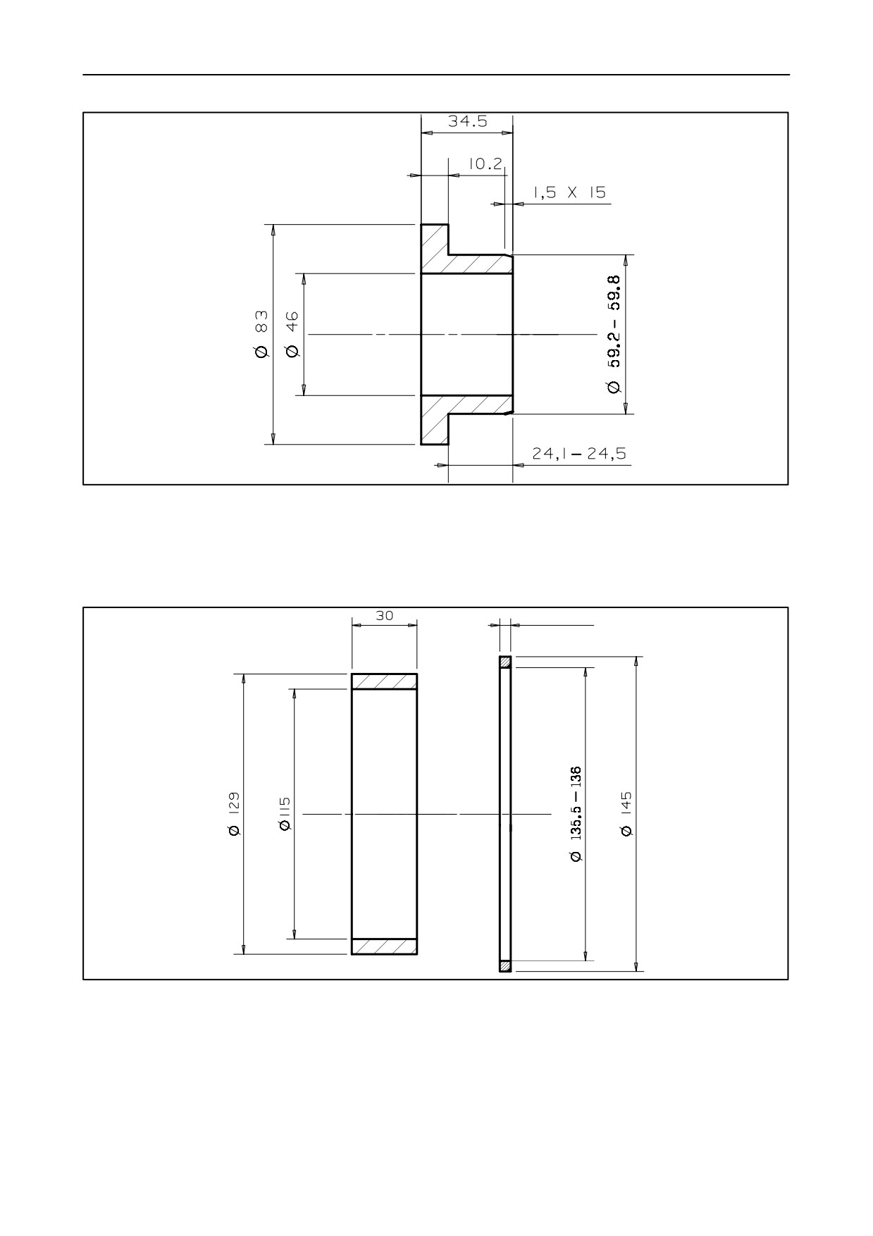
26
SECTION 10 -- ENGINE -- CHAPTER 1
26102
1
Splining tool to be manufactured for assembling the crankshaft front seal
(print No. 50138 on the tool -- Values in mm).
Make in UNI C40 material.
3.8 to 4
26103
2
Splining tool to be manufactured for assembling the crankshaft rear seal
(print No. 50139 on the tool -- Values in mm).
Make in UNI C40 material.
603.54.381.00 -- 05 -- 2001
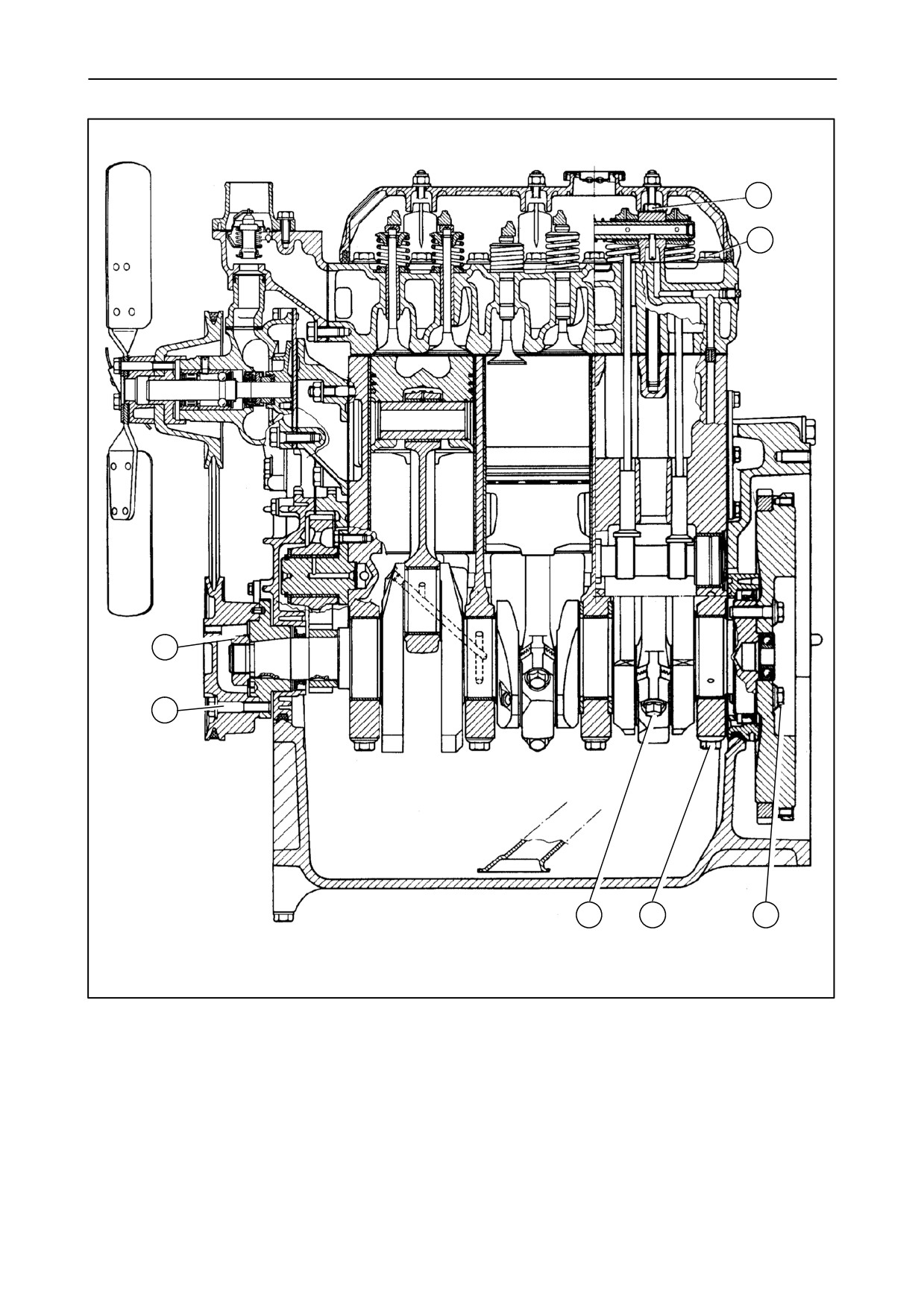
SECTION 10 -- ENGINE -- CHAPTER 1
27
1
2
7
6
5
4
3
25355
3
Engine longitudinal cross section -- 3--cylinder model TK 65.
603.54.381.00 -- 05 -- 2001
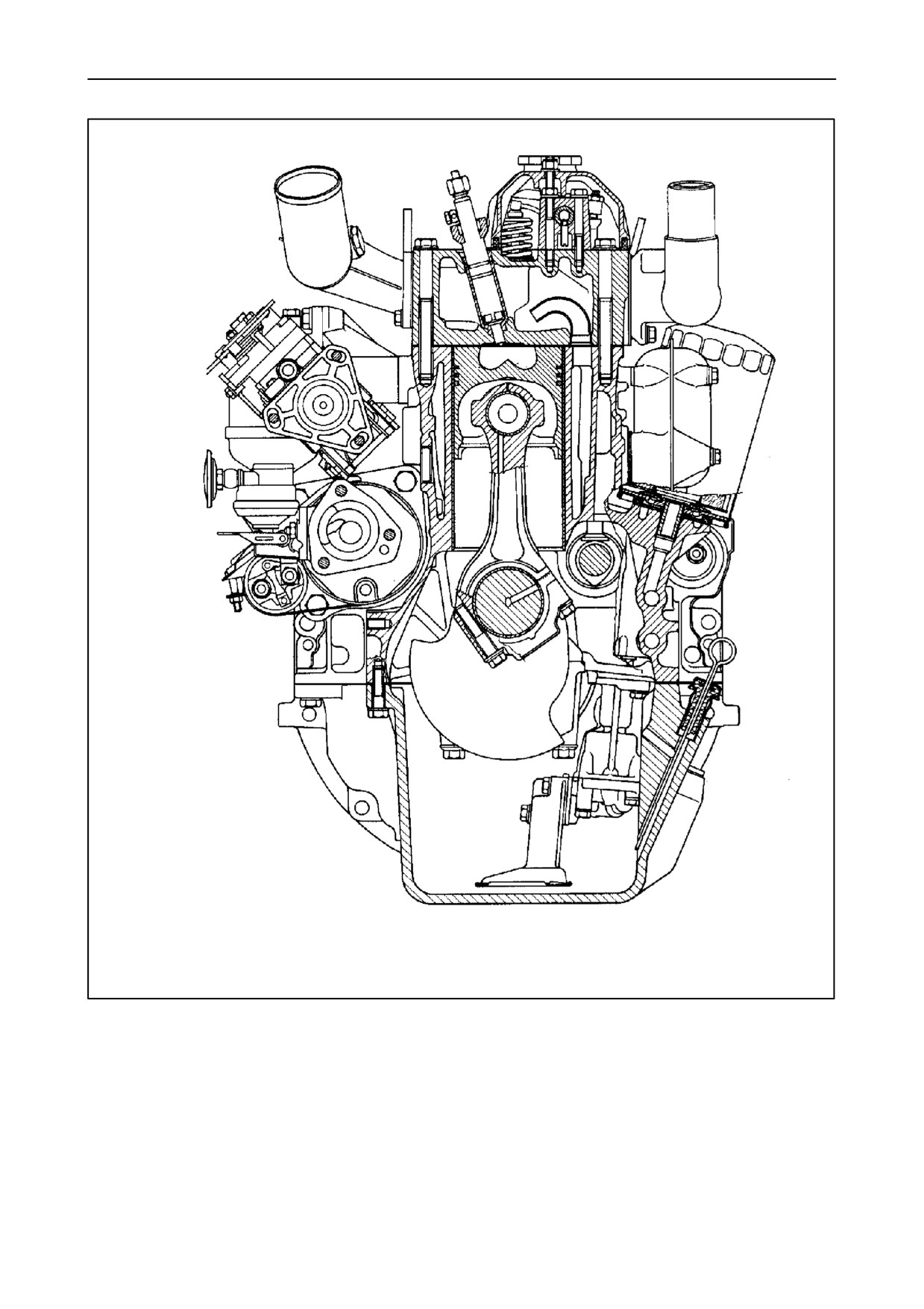
28
SECTION 10 -- ENGINE -- CHAPTER 1
25356
4
Engine cross section -- 3--cylinder model TK 65.
603.54.381.00 -- 05 -- 2001
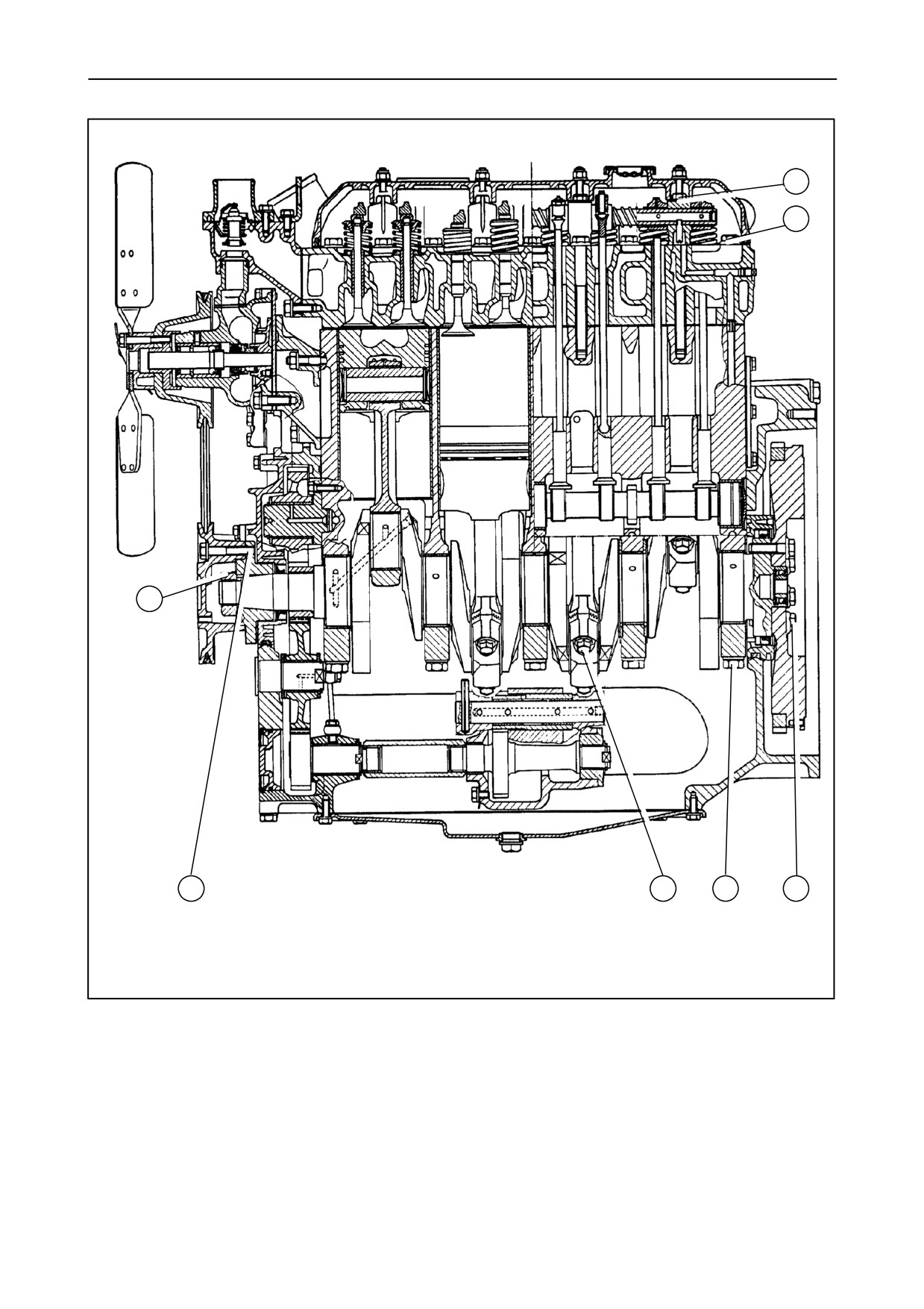
SECTION 10 -- ENGINE -- CHAPTER 1
29
1
2
7
6
5
4
3
25357
5
Engine longitudinal cross section -- 4--cylinder models TK 76 and TK 85.
603.54.381.00 -- 05 -- 2001
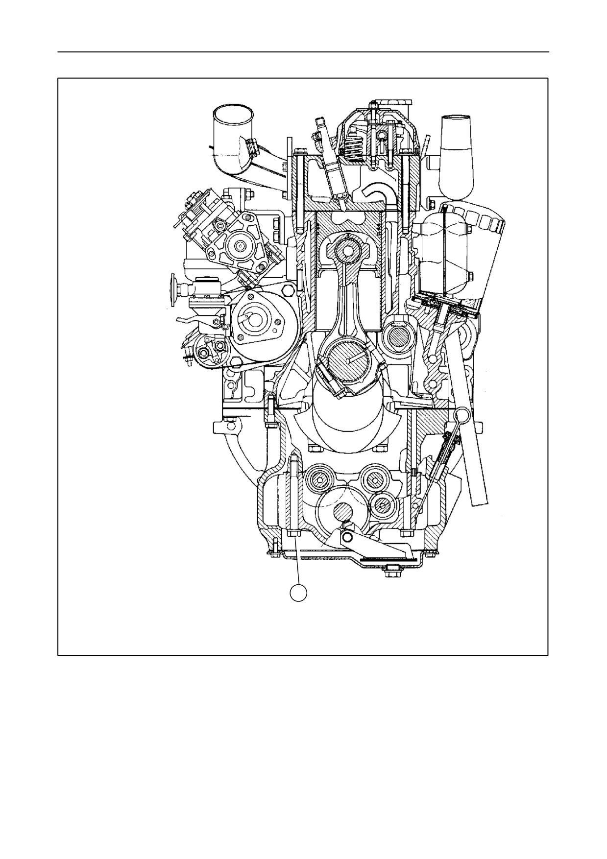
30
SECTION 10 -- ENGINE -- CHAPTER 1
1
25358
6
Engine longitudinal cross section -- 4--cylinder models TK 76 and TK 85.
603.54.381.00 -- 05 -- 2001