New Holland T4.55S / T4.65S / T4.75S Tractor. SERVICE MANUAL (2018)
SERVICE MANUAL
T4.55S / T4.65S / T4.75S
Tractor
Part number 51489991
English
May 2018
SERVICE MANUAL
T4.55 S
T4.65 S
T4.75 S
51489991 27/06/2018
EN
Link Product / Engine
Product
Market Product
Engine
T4.55 S Four-Wheel Drive (4WD)
Australia New Zealand
8035.25C.313T
with cab
T4.65 S Four-Wheel Drive (4WD)
Australia New Zealand
8035.25C.313T
with cab
T4.75 S Four-Wheel Drive (4WD)
Australia New Zealand
8035.25C.313T
with cab
5148999127/06/2018
Contents
Maintenance
00
[00.100] New unit pre-delivery operations
00.1
[00.150] Start-up
00.2
Engine
10
[10.001] Engine and crankcase
10.1
Clutch
18
[18.110] Clutch and components
18.1
Transmission
21
[21.114] Mechanical transmission
21.1
[21.112] Power shuttle transmission
21.2
Four-Wheel Drive (4WD) system
23
[23.101] Mechanical control
23.1
[23.304] Four-Wheel Drive (4WD) gearbox
23.2
Front axle system
25
[25.100] Powered front axle
25.1
Rear axle system
27
[27.100] Powered rear axle
27.1
Power Take-Off (PTO)
31
[31.101] Rear mechanical control
31.1
[31.104] Rear electro-hydraulic control
31.2
[31.114] Two-speed rear Power Take-Off (PTO)
31.3
Brakes and controls
33
[33.202] Hydraulic service brakes
33.1
[33.220] Trailer brake hydraulic control
33.2
Hydraulic systems
35
5148999127/06/2018
[35.000] Hydraulic systems
35.1
[35.204] Remote control valves
35.2
[35.116] Three-point hitch cylinder
35.3
Steering
41
[41.101] Steering control
41.1
[41.200] Hydraulic control components
41.2
[41.216] Cylinders
41.3
Cab climate control
50
[50.100] Heating
50.1
[50.200] Air conditioning
50.2
Electrical systems
55
[55.000] Electrical system
55.1
[55.100] Harnesses and connectors
55.2
[55.201] Engine starting system
55.3
[55.301] Alternator
55.4
[55.302] Battery
55.5
[55.512] Cab controls
55.6
[55.051] Cab Heating, Ventilation, and Air-Conditioning (HVAC) controls
55.7
Front loader and bucket
82
[82.300] Bucket
82.1
Platform, cab, bodywork, and decals
90
[90.150] Cab
90.1
5148999127/06/2018
SERVICE MANUAL
Maintenance
T4.55 S
T4.65 S
T4.75 S
51489991 27/06/2018
00
Contents
Maintenance - 00
[00.100] New unit pre-delivery operations
00.1
[00.150] Start-up
00.2
51489991 27/06/2018
00

CONSUMABLES INDEX
Consumable
Reference
PAGE
NEW HOLLAND AMBRA
Start-up - Technical Data LIQUID AND OIL CAPACITIES
00.2 / 4
AGRIFLU
NEW HOLLAND AMBRA
Start-up - Technical Data LIQUID AND OIL CAPACITIES
00.2 / 4
ACTIFULL™ OT EXTENDED
LIFE COOLANT
NEW HOLLAND AMBRA
Start-up - Technical Data LIQUID AND OIL CAPACITIES
00.2 / 4
UNITEK 10W-40
NEW HOLLAND AMBRA
Start-up - Technical Data LIQUID AND OIL CAPACITIES
00.2 / 4
UNITEK SSL 0W-40
NEW HOLLAND AMBRA
Start-up - Technical Data LIQUID AND OIL CAPACITIES
00.2 / 4
BRAKE LHM
NEW HOLLAND AMBRA
Start-up - Technical Data LIQUID AND OIL CAPACITIES
00.2 / 4
MULTI G™ HYDRAULIC
TRANSMISSION OIL
NEW HOLLAND AMBRA
Start-up - Technical Data LIQUID AND OIL CAPACITIES
00.2 / 4
MASTERTRAN®
ULTRACTION
NEW HOLLAND AMBRA
Start-up - Technical Data LIQUID AND OIL CAPACITIES
00.2 / 4
GR-9 MULTI-PURPOSE
GREASE
51489991 27/06/2018
00
51489991 27/06/2018
00
Maintenance - 00
New unit pre-delivery operations - 100
T4.55 S
T4.65 S
T4.75 S
51489991 27/06/2018
00.1 [00.100] / 1
Contents
Maintenance - 00
New unit pre-delivery operations - 100
FUNCTIONAL DATA
New unit pre-delivery operations
Overview GENERAL INSTRUCTION
3
51489991 27/06/2018
00.1 [00.100] / 2
Maintenance - New unit pre-delivery operations
New unit pre-delivery operations - Overview GENERAL
INSTRUCTION
NOTE: Take due care and attention during all maintenance and repairs.We recommend you work with a service center
authorized by NEW HOLLAND. Each section contains warnings for careful maintenance. Do not make adjustments
without the necessary special tools. Anyone who carries out procedures outside of a service center is responsible for
those procedures.
SHIMS
When adjusting with shims, collect the values found by measuring each shim separately with a micrometer. Do not
simply consider the nominal thickness values given on the shims or the overall thickness of the shim.
ROTATING SHAFT SEALS
To correctly position the rotating shaft seals, carry out the following steps:
1. Before you position the seal in its recess, soak the seal in oil for at least half an hour to ensure the seal sits in its
location properly.
2. Carefully clean the shafts and ensure that the seal and contact surface are not worn.
3. Turn the seal so that its edge moves towingard the oil. If the seal is an oil-recycling seal, turn the seal so that the
grooved lip goes into the oil. Thus, oil is expelled while the shaft rotates.
4. Coat the seal lips with a light oil (choose engine oil rather than grease). Fill the gap between the seal lip and the
dust prevention lip with grease. (also applicable to double-lip seal)
5. Position the seal with a flat-tipped tool. Do not use a hammer.
6. When you position the seal in its recess, ensure the seal is not positioned at an angle. Make sure that the seal fits
snugly into its recess by applying a constant pressure perpendicular to the seal surface.
7. When you slide the seal along the shaft, use a protective sleeve to protect the seal lips.
O-RINGS
Oil each O-ring before you position the O-ring. When you install the O-ring, slide the O-ring flat along the part, but do
not twist. Otherwise, a leak will occur.
LIQUID SEALS
Apply one of the following sealants to the join surfaces marked with an ‘X’: RTV SILMATE, RHODORSIL CAF 1, or
LOCTITE PLASTIC GASKET
Do the following to the joint surfaces before you apply the sealant:
1. Clean away debris thoroughly with a wire brush.
2. Thoroughly clean and degrease the surfaces with a mixture of hot water and soda or solvent gas oil.
BEARINGS
When you position the bearings:
1. Heat the bearings to 80-90 °C before you position the bearings on the shaft.
2. Cool the bearings before you hammer the bearings into their housings.
PINS
When you position beveled spring pins, make sure that the cut end of the pin is installed perpendicularly to the direction
of work. Spiral spring pins can be placed in any position.
51489991 27/06/2018
00.1 [00.100] / 3
Maintenance - New unit pre-delivery operations
REPLACEMENT PARTS
Only use genuine NEW HOLLAND replacement parts. Genuine parts are durable and safe.Genuine NEW HOLLAND
replacement parts guarantee quality, durability, and safety.
Specify the following information when you request replacement parts:
1. Tractor model and chassis number
2. Engine type and number
3. Part number (specified in the spare parts catalog or on barcodes)
SERVICE TOOLS
Tools detailed in the service catalog
1. These tools have been specially produced for NEW HOLLAND tractors.
2. They are essential for safe repair.
3. They are manufactured and tested to be robust and efficient work tools.
Use these special tools to ensure:
1. Optimum working conditions
2. The best results
3. Time and energy savings
4. Safer operation
ATTENTION: The wear limit values recommended for some parts are provided as an indication only. When references
are made to the “front”, “rear”, “right”, and “left”, these are from the driver’s perspective when facing forward.
51489991 27/06/2018
00.1 [00.100] / 4
Index
Maintenance - 00
New unit pre-delivery operations - 100
New unit pre-delivery operations - Overview GENERAL INSTRUCTION
3
51489991 27/06/2018
00.1 [00.100] / 5
51489991 27/06/2018
00.1 [00.100] / 6
Maintenance - 00
Start-up - 150
T4.55 S
T4.65 S
T4.75 S
51489991 27/06/2018
00.2 [00.150] / 1
Contents
Maintenance - 00
Start-up - 150
TECHNICAL DATA
Start-up
Technical Data LIQUID AND OIL CAPACITIES
4
FUNCTIONAL DATA
Start-up
Overview
5
OPERATING
Start-up
Warning SAFETY PRECAUTIONS
7
51489991 27/06/2018
00.2 [00.150] / 2

CONSUMABLES INDEX
Consumable
Reference
PAGE
NEW HOLLAND AMBRA
Start-up - Technical Data LIQUID AND OIL CAPACITIES
00.2 / 4
AGRIFLU
NEW HOLLAND AMBRA
Start-up - Technical Data LIQUID AND OIL CAPACITIES
00.2 / 4
ACTIFULL™ OT EXTENDED
LIFE COOLANT
NEW HOLLAND AMBRA
Start-up - Technical Data LIQUID AND OIL CAPACITIES
00.2 / 4
UNITEK 10W-40
NEW HOLLAND AMBRA
Start-up - Technical Data LIQUID AND OIL CAPACITIES
00.2 / 4
UNITEK SSL 0W-40
NEW HOLLAND AMBRA
Start-up - Technical Data LIQUID AND OIL CAPACITIES
00.2 / 4
BRAKE LHM
NEW HOLLAND AMBRA
Start-up - Technical Data LIQUID AND OIL CAPACITIES
00.2 / 4
MULTI G™ HYDRAULIC
TRANSMISSION OIL
NEW HOLLAND AMBRA
Start-up - Technical Data LIQUID AND OIL CAPACITIES
00.2 / 4
MASTERTRAN®
ULTRACTION
NEW HOLLAND AMBRA
Start-up - Technical Data LIQUID AND OIL CAPACITIES
00.2 / 4
GR-9 MULTI-PURPOSE
GREASE
51489991 27/06/2018
00.2 [00.150] / 3

Maintenance - Start-up
Start-up - Technical Data LIQUID AND OIL CAPACITIES
SPECIFICATION
AMOUNT
PRODUCT RECOMMENDED BY
NEW HOLLAND
Engine Cooling System
Conventional coolant: NEW HOLLAND
AMBRA AGRIFLU
mixed 50% with distilled waterAlternative
type coolant: NEW HOLLAND AMBRA
On the T4.55S and T4.65S series
9L
ACTIFULL™ OT EXTENDED LIFE
On the T4.75S series
11 L
COOLANT
(If the premixed coolant is not available,
mix the concentrate with 50% distilled
water)
Windshield Washer Fluid Container
Water with Detergent
On all models
2L
Fuel Tank
Stabilized, Filtered Diesel
On all models
82 L
Crank Case Oil
Unfiltered
On the T4.55S and T4.65S series
7,9 L
NEW HOLLAND AMBRA UNITEK
On the T4.75S series
9.3 L
10W-40 or NEW HOLLAND AMBRA
UNITEK SSL 0W-40
Filtered
On the T4.55S and T4.65S series
8.6 L
On the T4.75S series
10 L
Braking Unit
NEW HOLLAND AMBRA BRAKE LHM
On all models
0,7 L
Front Axle
On all models
Front Axle Casing
6L
NEW HOLLAND AMBRA MULTI G™
Front Axle Reducer (each)
1L
HYDRAULIC TRANSMISSION OIL
orNEW HOLLAND AMBRA
Powershuttle Transmission
MASTERTRAN® ULTRACTION
On all models
35 L
Air Conditioning System Coolant Gas
On all models
1.50 kg
Front Wheel Wheel Rim Hub
-
On all models
NEW HOLLAND AMBRA GR-9
All Grease Points
MULTI-PURPOSE GREASE
-
On all models
51489991 27/06/2018
00.2 [00.150] / 4
Maintenance - Start-up
Start-up - Overview
OPERATION
1. Do not operate the engine in an enclosed environment with insufficient ventilation for exhaust gas emissions.
2. Do not insert your head, your body, feet, fingers, or arms between the rotating parts of the fan or the belt.
ENGINE
1. Before you remove the radiator cap, turn the cap slowly to reduce the pressure. Add water to the engine when the
engine is at a standstill, or in idle when the engine is warm.
2. Make sure that the engine is stopped when you refuel. Be careful when the engine is hot, as the fuel may ignite.
3. Never check or adjust the fan belts when the engine is running. Do not adjust the fuel pump while the engine is
running.
4. Never lubricate while the engine is running.
ELECTRICAL SYSTEM
1. When you use the auxiliary battery, make sure that the cable end connections to the terminals are (+) to (+) and
(-) to (-). Do not short the ends. BATTERY VAPOR IGNITES VERY QUICKLY. While the battery is charging, open
the battery plugs to ensure adequate ventilation. Do not place metal items between the terminals to check the
battery charge. Protect the battery from light and sparks. Do not smoke near the battery.
2. Check for fuel and battery electrolyte leaks before you carry out servicing or maintenance. Repair any leaks before
you start work.
3. Do not charge the battery in an enclosed area. After the battery is charged, ensure cropper ventilation so that
explosive gasses produced during battery charging can escape.
4. Disconnect the battery before any repair work, or before you start work on the electrical system.
HYDRAULIC SYSTEM
1. Pressurized liquid leaking from a very small hole may not be visible and can damage your skin. As such, DO NOT
CHECK FOR LEAKS WITH YOUR HANDS. Use a piece of wood or cardboard to check for leaks. Seek medical
attention if you are injured by leaking liquid. If you do not receive immediate medical attention, a serious infection
or reaction may develop.
2. When you check the pressure, use an indicator appropriate for the expected pressure.
WHEELS AND TIRES
1. Ensure that tires are inflated to the pressure values indicated by their manufacturer. Check tires periodically for
wear.
2. Take care when you adjust tire pressure and position yourself safely.
3. Check tire pressure with the tractor empty. To avoid over-inflation, only check tires when they are cold. Do not use
worn tires. Improper welding heating or soldering reduces the resistance of the wheels and causes the wheels to
malfunction.
4. Never weld inflated tires to the rims.
5. Use chocks on the front and rear wheels when you carry out tire maintenance. After you raise the tractor on a
jack, position a support stand underneath the tractor to prevent the tractor from falling.
6. Deflate the tires before you remove items that may cause tires to burst from the tire tread.
7. Never inflate tires with flammable gas. This can cause explosions and injury.
EQUIPMENT
1. Use lifters with appropriate capacities to lift heavy parts. Make sure that parts are properly supported (with rings
hooks, rings, etc.). Use a jack if necessary. Be aware of people around you.
51489991 27/06/2018
00.2 [00.150] / 5
Maintenance - Start-up
2. Be very careful when you carry parts. Take care not to trap fingers or toes. Wear work gloves, shoes, and safety
glasses as instructed by the authorities.
3. Look out for twisted chains and cables. Always wear thick gloves when handling chains and cables manually.
51489991 27/06/2018
00.2 [00.150] / 6
Maintenance - Start-up
Start-up - Warning SAFETY PRECAUTIONS
ATTENTION: WARNINGS ARE THERE FOR YOUR HEALTH AND SAFETY. BE CAUTIOUS AND AWARE.
AVOID ACCIDENTS.
Most accidents in workshops can be avoided by observing basic safety rules. Most accidents can be avoided by taking
precautionary measures and applying the safety rules. No matter how well equipment is designed or manufactured,
unsafe situations that hinder your ability to access and to work with equipment may still exist. The best insurance
against an accident is a careful user. By following all of the basic rules below, you can avoid the risk of serious
accident.
ATTENTION: Never lubricate or make adjustments when the tractor is running.
SAFETY PRECAUTIONS
1.
Carry out specified maintenance and repair procedures in full.
2.
While you work, avoid wearing clothes or items that may become caught in moving parts such as rings, watches,
jewelry, torn or loose clothing, ties, scarves, buttons, or zips. Use protective helmets, boots, gloves, and goggles.
3.
Do not service the tractor without someone to start the tractor.
4.
Never operate the tractor without sitting in the driver's seat. Never use the equipment other than in the ways
specified.
5.
Never lubricate, service, or make adjustments while the engine is running.
6.
Stop the engine and check whether the hydraulic system is pressurized before you remove covers or caps.
7.
Carry out all service procedures with utmost care and diligence.
8.
Platforms and ladders used in the workshop or in the field for tractor maintenance and repair should be manu-
factured to respond to local or national conditions.
9.
Disconnect the battery and the start controls when you work. Make sure that equipment to be lifted is under
control.
10.
Because of the presence of flammable substances, do not refuel, or check or replenish the battery fluid while you
are smoking or near a flame.
11.
When the tractor is in neutral, use chocks or another method when you service the brakes to ensure that the
tractor is secure and under control.
12.
Only use the specified towing hitch points. Before you towing, make sure that locking equipment and pins are
working. Under load, stand away from chains, cables, and towing hooks.
13.
To prevent static electricity or any kind of spark when you refuel, make sure that the fuel nozzle is in contact with
the tank.
14.
To move a non-operational tractor, use a towing truck or a low-body truck if available.
15.
Make sure that the truck wheels are secured when you load or unload the tractor. Place chocks under the tractor
wheels after you have loaded the tractor on the truck.
16.
To reduce the risk of electric shock, only use grounded auxiliary hydraulic valves to charge devices, pumps, and
similar equipment.
17.
Lift heavy parts with appropriate machinery.
18.
Be aware of those around you when you work with the tractor.
19.
Do not put diesel in open containers.
20.
Never use diesel, solvents, or other flammable liquids to clean parts. Always use flame resistant, non-toxic sol-
vents.
21.
Wear protective goggles when you use pressurized air to clean parts.
22.
In accordance with national regulations, limit air pressure to 2,1 bar.
23.
To not run the engine in buildings with inadequate ventilation.
24.
Do not smoke when you work with flammable materials.
25.
Do not use an open-flame lighting device to carry out any checks on the tractor or to check for leaks.
51489991 27/06/2018
00.2 [00.150] / 7
Maintenance - Start-up
26.
Be careful when you are near, in, or near a tractor or equipment. Wear appropriate safety equipment (protective
helmets, goggles, boots).
27.
When you check equipment when the engine is running, the driver should be seated in the driver's seat. Take
the nature of the equipment into account.
28.
When you service the tractor in the field position the tractor on flat ground, if possible.
29.
If this is not possible, use chocks to secure the tractor and equipment. Position the tractor on flat ground as soon
as possible.
30.
Watch out for twisted chains or cables. Do not lift or towing the tractor with twisted chains. Use thick gloves when
you use chains or cables.
31.
Make sure that cables are hooked and that the connection points are strong enough for the prescribed loads.
Move people away from the connection points of chains and cables.
32.
Keep your service area dry and clean. Clean the water or oil deposits.
33.
Keep highly flammable material such as oily rags or grease cloths in a closed metal container. Check, adjust,
and lock the driver’s seat before you start the tractor. Make sure that no one is in the vicinity of the tractor.
34.
Do not carry items in your pockets that could fall into spaces within the tractor.
35.
If you do drop an item, wear protective goggles, steel-capped boots, thick gloves, and a hard hat when you try to
retrieve the item.
36.
Wear protective clothing, a helmet, and dark protective glasses when you weld. Make sure that those around
you also wear dark protective glasses while you weld. DO NOT LOOK AT WELDING LIGHT WITHOUT PRO-
TECTIVE GLASSES
37.
Metal shavings may be present on steel wires. Use work gloves and protective gloves when you handle steel
wires.
38.
Hold parts carefully. Make sure that your hands or fingers do not get trapped between parts. Wear safety glasses,
gloves, and boots as recommended by the authorities.
51489991 27/06/2018
00.2 [00.150] / 8
Index
Maintenance - 00
Start-up - 150
Start-up - Overview
5
Start-up - Technical Data LIQUID AND OIL CAPACITIES
4
Start-up - Warning SAFETY PRECAUTIONS
7
51489991 27/06/2018
00.2 [00.150] / 9
CNHI International. Guvercin Yolu No 111-112 Gazi Ankara Turkey
SERVICE - Technical Publications & Tools
PRINTED IN TURKEY
No part of the text or illustrations of this publication may be reproduced.
CNHI International reserves the right to make improvements in design and changes in specifications at any
time without notice and without incurring any obligation to install them on units previously sold. Specifications,
descriptions, and illustrative material herein are as accurate as known at the time of publication, but are subject
to change without notice.
Availability of some models and equipment builds varies according to the country in which the equipment is being
used. For exact information about any particular product, please consult your NEW HOLLAND dealer.
NEW HOLLAND is a trademark registered in the United States and many other countries, owned or licensed to CNH
Industrial N.V., its subsidiaries or affiliates.
Any trademarks referred to herein, in association with goods and/or services of companies, other than owned by or
licensed to CNH Industrial N.V., its subsidiaries or affiliates, are the property of those respective companies.
51489991 27/06/2018
EN
SERVICE MANUAL
Engine
T4.55 S
T4.65 S
T4.75 S
51489991 27/06/2018
10
Contents
Engine - 10
[10.001] Engine and crankcase
10.1
51489991 27/06/2018
10
Engine - 10
Engine and crankcase - 001
T4.55 S
T4.65 S
T4.75 S
51489991 27/06/2018
10.1 [10.001] / 1
Contents
Engine - 10
Engine and crankcase - 001
SERVICE
Engine and crankcase
Disassemble
3
51489991 27/06/2018
10.1 [10.001] / 2
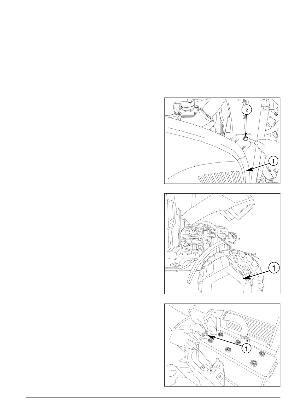
Engine - Engine and crankcase
Engine and crankcase - Disassemble
MOTOR — Sökme
ATTENTION: Please use suitable equipments during the operations..
Make sure that the body and parts are securely supported with elements such as rope and hooks. Ensure that no
one is nearby when the load is removed.
ATTENTION: Use appropriate tools to align the holes in the parts. NEVER USE YOUR FINGERS AND HANDLERS.
Follow the below operations.
1. To reach the motor it is necessary to remove the pro-
tective covers (1) on both sides.
Disassemble the boltsı (2) and remove the covers.
ANIL17TRO0925AA
1
2. Drain the coolant gas with A/C device (1) . Connect the
pressure (red) pipe to red hall on the compressor and
connect the blue pipe as the same.
ANIL17TRO0926AA
2
3. Disconnect the battery terminal (1) .
ANIL17TRO0927AA
3
51489991 27/06/2018
10.1 [10.001] / 3
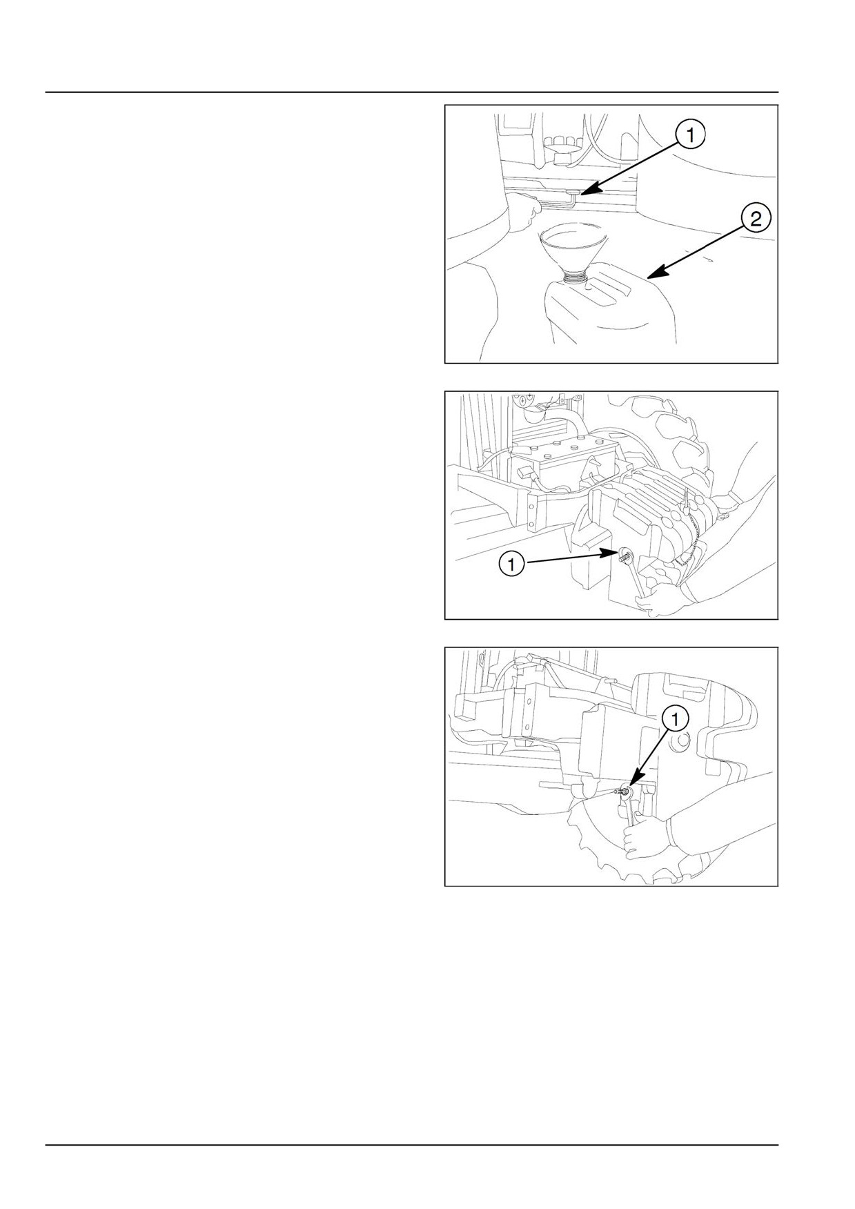
Engine - Engine and crankcase
4. Engage the hand brake.. Disassemble the engine oil
drain plug (1). Drain the oil to the suitable container (2)
and make the same operations for transmission oil.
ANIL17TRO0928AA
4
5. Remove the front weight connection rod (1).
ANIL17TRO0992AA
5
6. Remove the front weight below connection rod (1).
ANIL17TRO0930AA
6
51489991 27/06/2018
10.1 [10.001] / 4
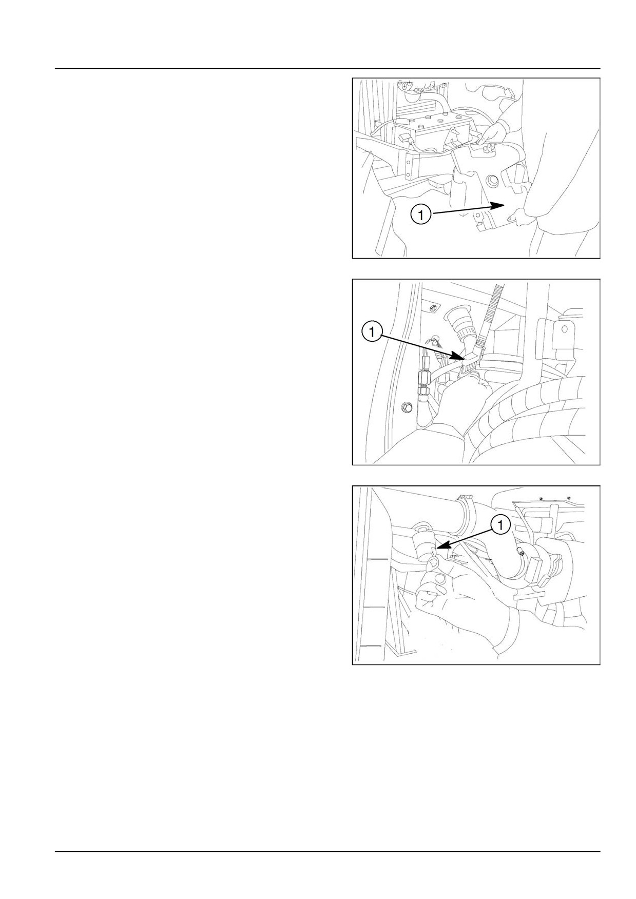
Engine - Engine and crankcase
7. Take out the front weights (1).
ANIL17TRO0931AA
7
8. Disconnect the electrical socket (1).
ANIL17TRO0932AA
8
9. Remove the electric socket of air filter pressure sensor
(1).
ANIL17TRO0933AA
9
51489991 27/06/2018
10.1 [10.001] / 5
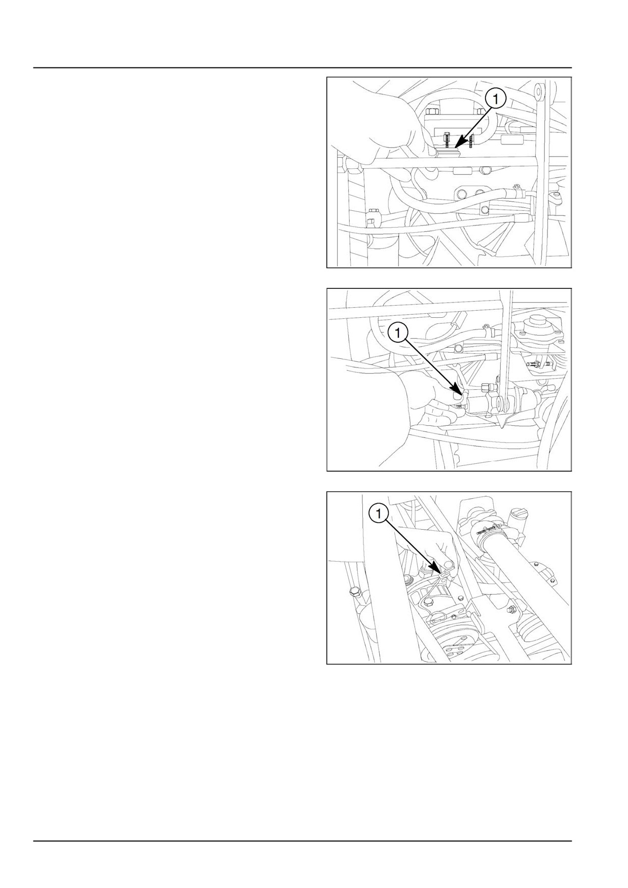
Engine - Engine and crankcase
10. Remove the heater electric socket that is placed on
inlet manifold (1).
ANIL17TRO0934AA
10
11. Remove the KSB connection socket (1).
ANIL17TRO0935AA
11
12. Disconnect the electric connection socket (1) with A/C
models.
ANIL17TRO0936AA
12
51489991 27/06/2018
10.1 [10.001] / 6
Engine - Engine and crankcase
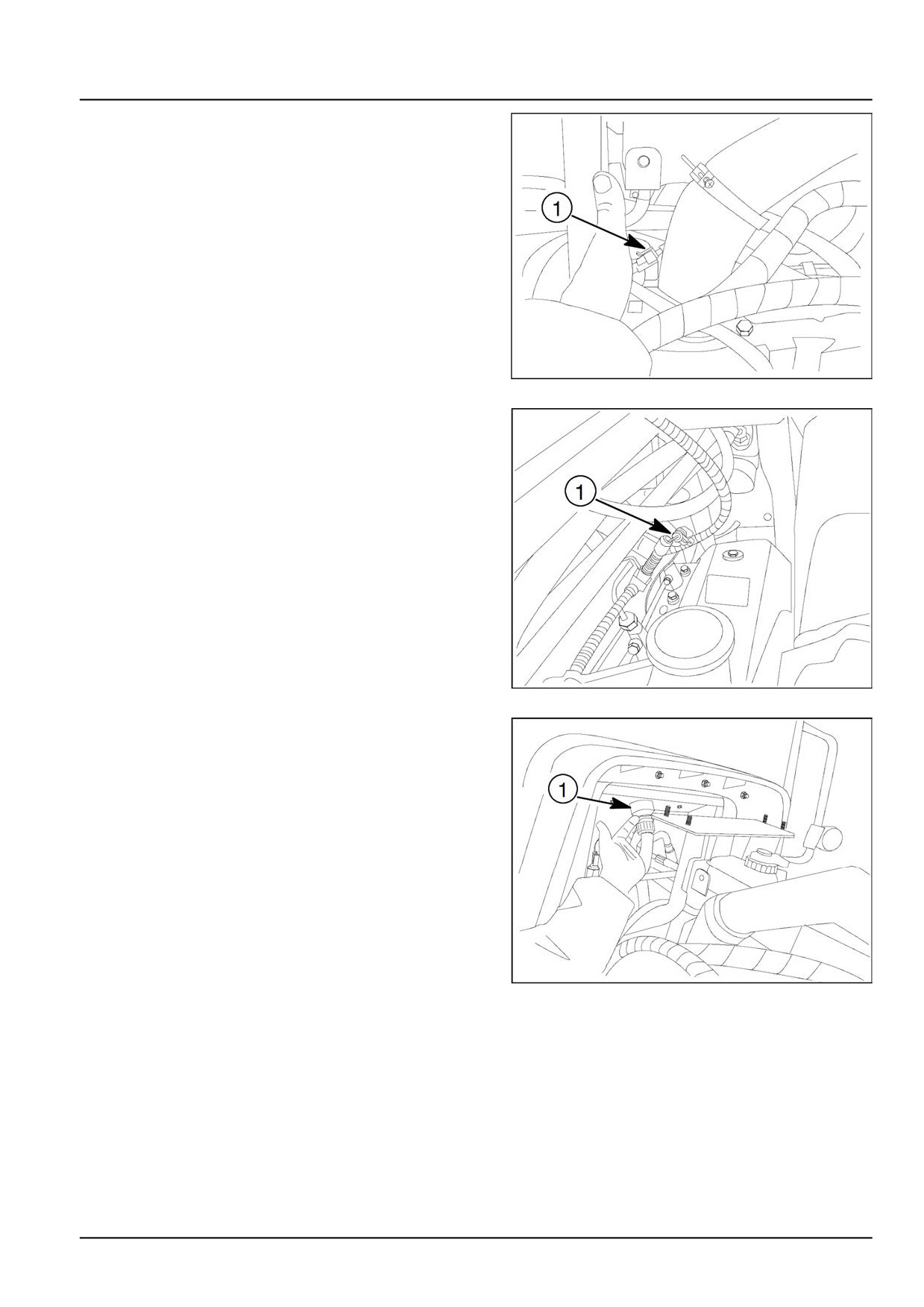
13. Disconnect the cable harness (1) which are came from
engine hood.
ANIL17TRO0937AA
13
14. Disconnect the electrical socket (1).
ANIL17TRO0938AA
14
15. Disconnect the main socket (1) where is used behind
the tractor.
ANIL17TRO0939AA
15
51489991 27/06/2018
10.1 [10.001] / 7
Engine - Engine and crankcase
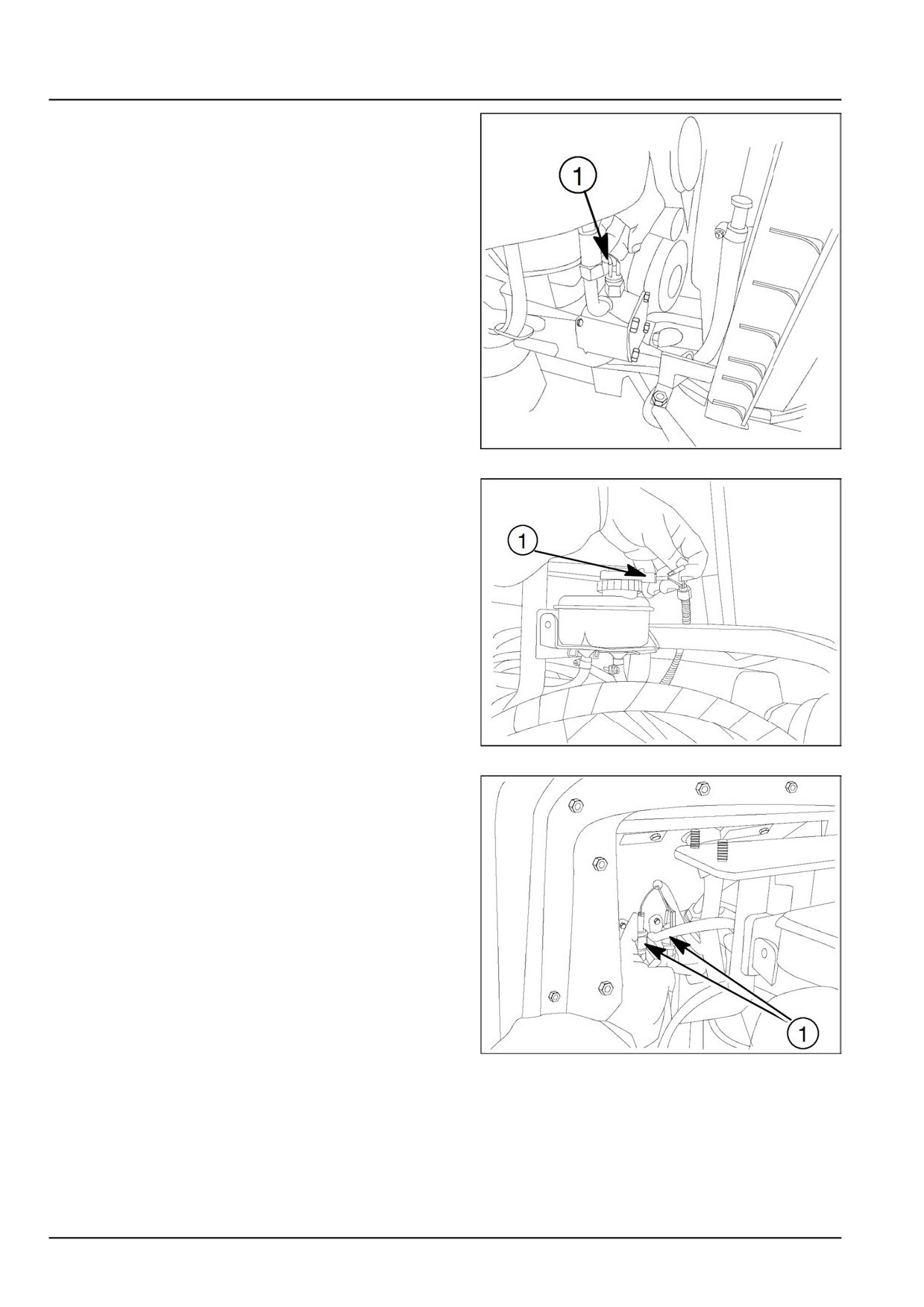
16. Disconnect the steering oil pressure sensor (1).
ANIL17TRO0940AA
16
17. Remove the brake hydraulic oil level socket (1)
ANIL17TRO0941AA
17
18. Remove the brake oil sensor sockets (1)
ANIL17TRO0942AA
18
51489991 27/06/2018
10.1 [10.001] / 8
Engine - Engine and crankcase
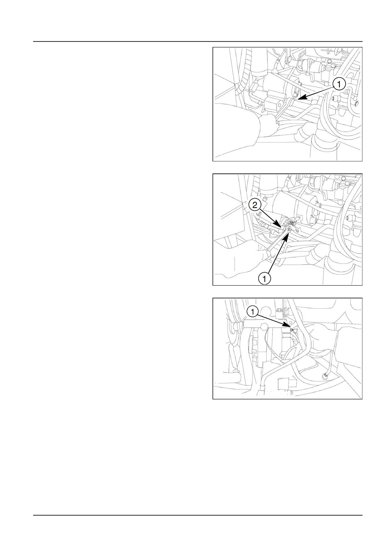
19. Remove the bolt which is placed on starter plastic pro-
tect (1) and extract the plastic part.
ANIL17TRO0943AA
19
20. Disconnect the bolt (1) Remove the electric connec-
tion (2).
ANIL17TRO0944AA
20
21. Remove the electric sockets (1) which are placed on
alternator.
ANIL17TRO0945AA
21
51489991 27/06/2018
10.1 [10.001] / 9
Engine - Engine and crankcase
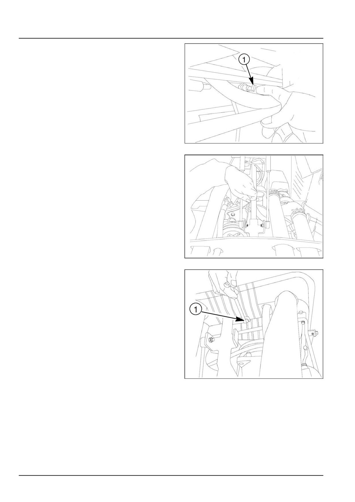
22. Remove the oil pressure switch electric socket (1).
ANIL17TRO0946AA
22
23. Disconnect the bolts (1) which are fixed on hood
bracket with hood shock absorber.
ANIL17TRO0947AA
23
24. Remove the fixed bolt (1) on plastic protective.
ANIL17TRO0948AA
24
51489991 27/06/2018
10.1 [10.001] / 10
Engine - Engine and crankcase
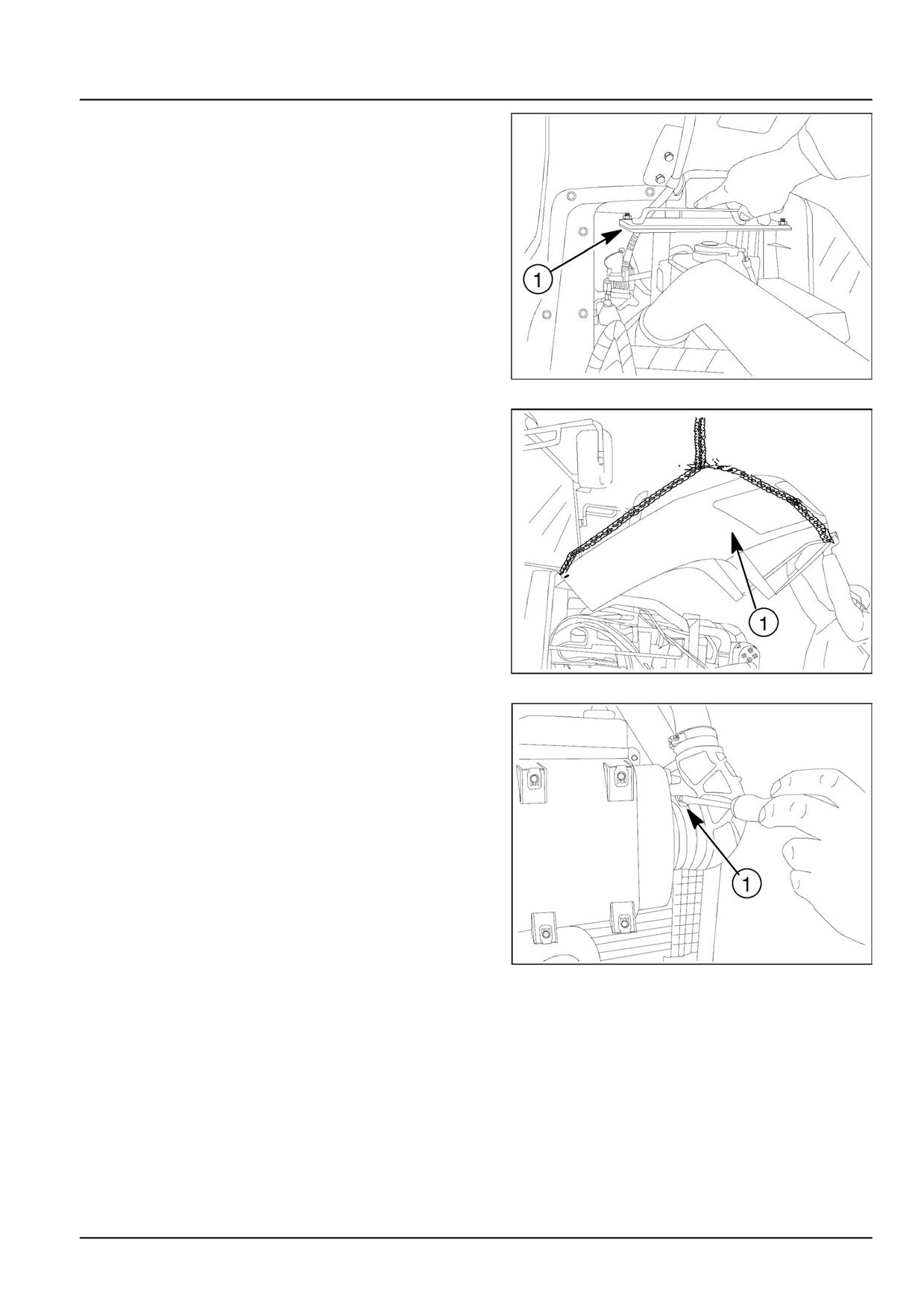
25. Remove the bolts (1) which are placed bracket behind
the hood.
ANIL17TRO0949AA
25
26. Lift the hood (1).
ANIL17TRO0950AA
26
27. Remove the fan aspiration clamp and remove the fan
aspiration pipe.
Remove the air filter plastic pipe clamp (1).
ANIL17TRO0951AA
27
51489991 27/06/2018
10.1 [10.001] / 11
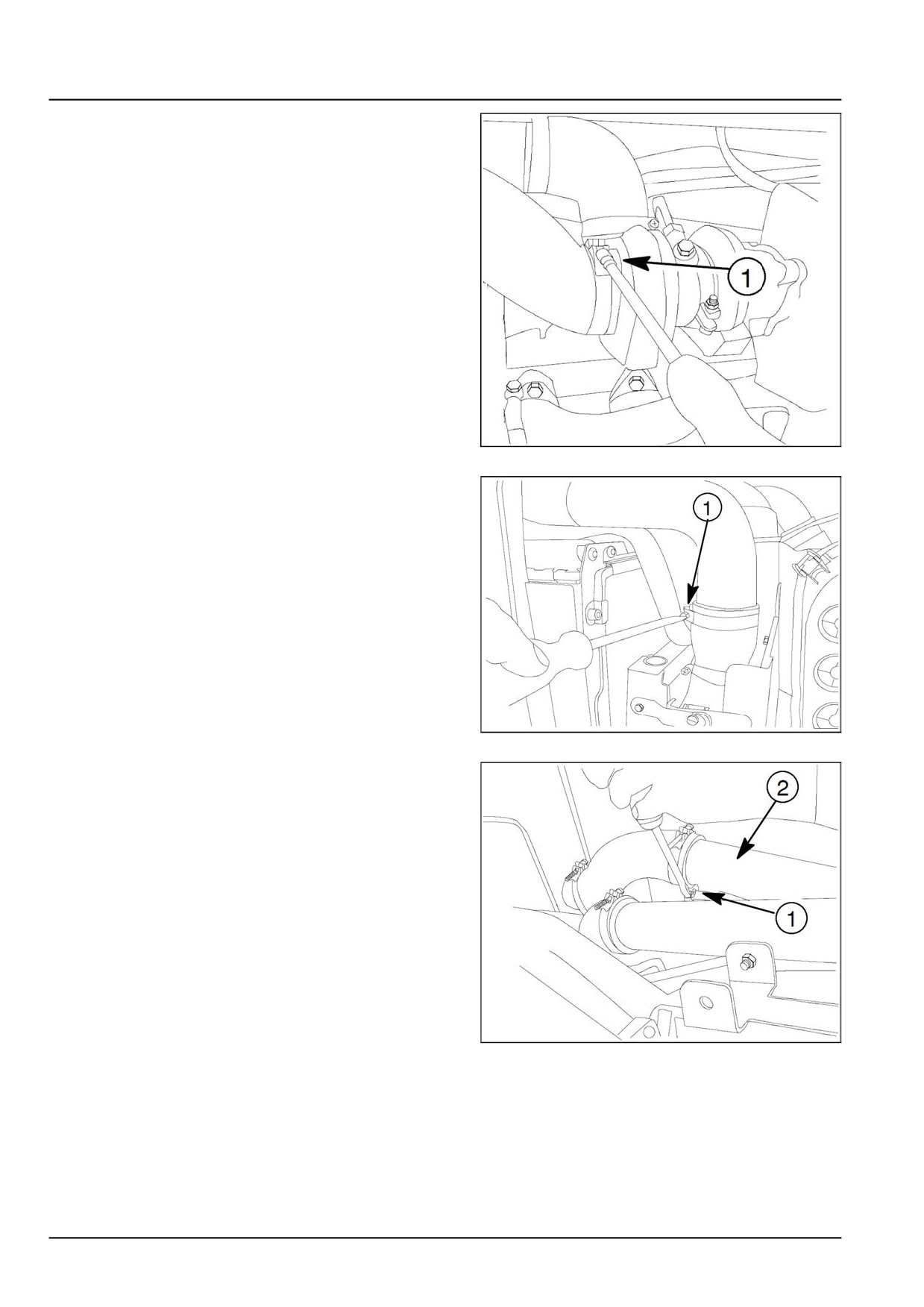
Engine - Engine and crankcase
28. Loose the turbocharger pipe clamp (1) and remove the
plastic air pipe from it’s hall.
ANIL17TRO0952AA
28
29. Loose the intercooler plastic pipe clamp (1) and re-
move the pipe.
ANIL17TRO0953AA
29
30. Loose the engine breather pipe (1) and remove it. Re-
move the air inlet pipe (2) .
ANIL17TRO0954AA
30
51489991 27/06/2018
10.1 [10.001] / 12
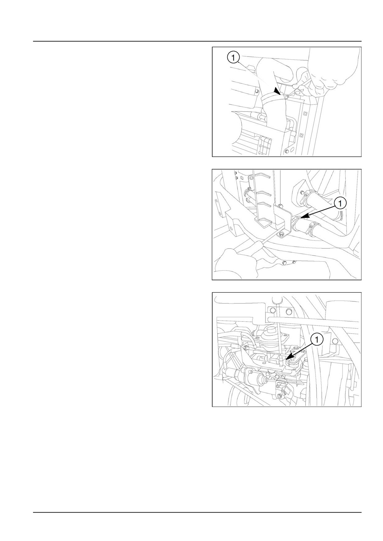
Engine - Engine and crankcase
31. Disassemble the air inlet pipe clamp (1) which is
placed between intercooler and turbocharger.
ANIL17TRO0956AA
31
32. Loose the clamp (1) where is placed between radiator
and water pump and remove from the radiator.
Remove the pipe from the water pump to radiator.
ANIL17TRO0958AA
32
33. Remove the hand throttle cable bracket bolt (1).
ANIL17TRO0959AA
33
51489991 27/06/2018
10.1 [10.001] / 13