New Holland T3.60F / T3.70F / T3.80F Tractor. SERVICE MANUAL (2018)
SERVICE MANUAL
T3.60F / T3.70F / T3.80F
Tractor
Part number 51553302
1st edition English
November 2018
SERVICE MANUAL
T3.60F
T3.70F
T3.80F
51553302 19/11/2018
EN
Link Product / Engine
Product
Market Product
Engine
T3.60F
North America
8035.25A IIIB
T3.70F
North America
8035.25B IIIB
T3.80F
North America
8035.25C IIIB
5155330219/11/2018
Contents
INTRODUCTION
Engine
10
[10.001] Engine and crankcase
10.1
Clutch
18
[18.110] Clutch and components
18.1
Transmission
21
[21.114] Mechanical transmission
21.1
[21.130] Mechanical transmission external controls
21.2
[21.112] Power shuttle transmission
21.3
[21.120] Gearbox
21.4
[21.160] Creeper
21.5
Four-Wheel Drive (4WD) system
23
[23.101] Mechanical control
23.1
[23.202] Electro-hydraulic control
23.2
[23.314] Drive shaft
23.3
Front axle system
25
[25.100] Powered front axle
25.1
[25.102] Front bevel gear set and differential
25.2
[25.108] Final drive hub, steering knuckles, and shafts
25.3
Rear axle system
27
[27.100] Powered rear axle
27.1
[27.106] Rear bevel gear set and differential
27.2
[27.120] Planetary and final drives
27.3
Hydrostatic drive
29
[29.300] Rear hydrostatic transmission
29.1
Power Take-Off (PTO)
31
5155330219/11/2018
[31.101] Rear mechanical control
31.1
[31.225] Clutches
31.2
Brakes and controls
33
[33.202] Hydraulic service brakes
33.1
[33.110] Parking brake or parking lock
33.2
[33.220] Trailer brake hydraulic control
33.3
Hydraulic systems
35
[35.525] Auxiliary hydraulic valves and lines
35.1
[35.100] Main lift system
35.2
[35.162] Front hitch cylinders and lines
35.3
Steering
41
[41.101] Steering control
41.1
[41.216] Cylinders
41.2
Wheels
44
[44.511] Front wheels
44.1
Electrical systems
55
[55.000] Electrical system
55.1
[55.100] Harnesses and connectors
55.2
[55.201] Engine starting system
55.3
[55.301] Alternator
55.4
[55.302] Battery
55.5
[55.013] Engine oil system
55.6
[55.512] Cab controls
55.7
[55.408] Warning indicators, alarms, and instruments
55.8
[55.DTC] FAULT CODES
55.9
Platform, cab, bodywork, and decals
90
[90.110] Operator platform less cab
90.1
5155330219/11/2018
Contents
INTRODUCTION
Safety rules
3
Basic instructions
7
51553302 19/11/2018
2
INTRODUCTION
Safety rules
Pay attention to this symbol
This warning symbol points out important messages con-
cerning your safety.
Carefully read the following safety regulations and ob-
serve advised precautions in order to avoid potential haz-
ards and safeguard your health and safety.
In this manual the symbol is accompanied by the following
key-words:
WARNING: Warnings concerning unsuitable repair oper-
ations that may jeopardise the safety of Repair personnel.
DANGER: Specific warnings concerning potential haz-
ANIL15TR0707AA
1
ards for operator safety or for other persons directly or
indirectly involved.
To prevent accidents
Most accidents or injuries that occur in workshops are the result of non-observance of simple and fundamental safety
regulations. For this reason, IN MOST CASES THESE ACCIDENTS CAN BE AVOIDED by foreseeing possible
causes and consequently acting with the necessary caution and care.
Accidents may occur with all types of vehicle, regardless of how well it was designed and built.
A careful and judicious service technician is the best guarantee against accidents.
Precise observance of the most basic safety rule is normally sufficient to avoid many serious accidents.
DANGER: Never carry out any cleaning, lubrication or maintenance operations when the engine is running.
Safety rules
General guidelines:
• Carefully follow specified repair and maintenance procedures.
• Do not wear rings, wristwatches, jewels, unbuttoned or flapping clothing such as ties, torn clothes, scarves, open
jackets or shirts with open zips which could get caught on moving parts.
Use approved safety clothing such as anti-slipping footwear, gloves, safety goggles, helmets, etc.
• Do not carry out repair operations with someone sitting in the driver’s seat, unless the person is a trained technician
who is assisting with the operation in question.
• Do not operate the vehicle or use any of the implements from different positions, other than the driver’s seat.
• Do not carry out operations on the vehicle with the engine running, unless specifically indicated.
• Stop the engine and ensure that all pressure is relieved from hydraulic circuits before removing caps, covers, valves,
etc.
• All repair and maintenance operations must be carried out using extreme care and attention.
• Service steps and platforms used in a workshop or in the field should be built in compliance with the safety rules in
force.
• Disconnect the batteries and label all controls to indicate that the vehicle is being serviced. Block the machine and
all equipment which should be raised.
• Do not check or fill fuel tanks, accumulator batteries, nor use starting liquid when smoking or near naked flames,
as these fluids are inflammable.
• Brakes are inoperative when manually released for repair or maintenance purposes. Use blocks or similar devices
to control the machine in these conditions.
51553302 19/11/2018
3
INTRODUCTION
•
The fuel nozzle should always be in contact with the filling aperture: Maintain this contact until the fuel stops flowing
into the tank to avoid possible sparks due to static electricity buildup.
•
Only use specified towing points for towing the vehicle. Connect parts carefully. Make sure that all pins and/or
locks are secured in position before applying traction. Never remain near the towing bars, cables or chains that are
operating under load.
•
Transport vehicles that cannot be driven using a trailer or a low-loading platform trolley, if available.
•
When loading or unloading the vehicle from the trailer (or other means of transport), select a flat area capable of
sustaining the trailer or truck wheels. Firmly secure the vehicle to the truck or trailer and lock the wheels in the
position used by the carrier.
•
Electric heaters, battery-chargers and similar equipment must only be powered by auxiliary power supplies with
efficient ground insulation to avoid electrical shock hazards.
•
Always use suitable hoisting or lifting devices when raising or moving heavy parts.
•
Take extra care if bystanders are present.
•
Never pour petrol or diesel oil into open, wide or low containers.
•
Never use gasoline, diesel oil or other inflammable liquids as cleaning agents. Use non-inflammable, non-toxic
commercially available solvents.
•
Wear safety goggles with side guards when cleaning parts with compressed air.
•
Limit the air pressure to a maximum of 2.1 bar, according to local regulations.
•
Do not run the engine in confined spaces without suitable ventilation.
•
Do not smoke, use naked flames, or cause sparks in the area when fuel filling or handling highly inflammable liquids.
•
All movements must be carried out carefully when working under, on or near the vehicle. Wear suitable safety
clothing, i.e., hard hat, safety goggles and special shoes.
•
When carrying out checks with the engine running, request the assistance of an operator in the driver’s seat. The
operator must maintain visual contact with the service technician at all times.
•
If operating outside the workshop, position the vehicle on a flat surface and lock in position. If working on a slope,
lock the vehicle in position. Move to a flat area as soon as is safely possible.
•
If operating outside the workshop, position the vehicle on a flat surface and lock in position. If working on a slope,
lock the vehicle in position.
Move to a flat area as soon as is safely possible.
•
Damaged or bent chains or cables are unreliable. Do not use them for lifting or towing. Always use suitable pro-
tective gloves when handling chains or cables.
•
Chains should always be safely secured. Make sure that the hitch-up point is capable of sustaining the load in
question. Keep the area near the hitch-up point, chains or cables free of all bystanders.
•
Maintenance and repair operations must be carried out in a CLEAN and DRY area. Eliminate any water or oil
spillage immediately.
•
Do not create piles of oil or grease-soaked rags as they represent a serious fire hazard. Always place them into a
metal container.
Before starting the tractor or its attachments, check, adjust and block the operator’s seat. Also check that there are
no persons within the vehicle or implement range of action.
•
Empty pockets of all objects that may fall unobserved into the vehicle parts.
•
In the presence of protruding metal parts, use protective goggles or goggles with side guards, helmets, special
footwear and gloves.
•
When welding, use protective safety devices: tinted safety goggles, helmets, special overalls, gloves and footwear.
All persons present in the area where welding is taking place must wear tinted goggles. NEVER LOOK DIRECTLY
AT THE WELDING ARC WITHOUT SUITABLE EYE PROTECTION.
•
Metal cables tend to fray with repeated use. Always use suitable protective devices (gloves, goggles, etc.) when
handling cables.
•
Handle all parts with great care. Do not put your hands or fingers between moving parts. Always wear suitable
safety clothing-safety goggles, gloves and shoes.
51553302 19/11/2018
4
INTRODUCTION
Starting
• Never run the engine in confined spaces that are not equipped with adequate ventilation for exhaust gas extraction.
• Never place the head, body, limbs, feet, hands or fingers near fans or rotating belts.
Engine
• Always loosen the radiator cap slowly before removing it to allow any remaining pressure in the system to be dis-
charged. Filling up with coolant should only be carried out with theengine stopped or idling (if hot).
• Never fill up with fuel when the engine is running, especially if hot, in order to prevent the outbreak of fire as a result
of fuel spillage.
• Never check or adjust fan belt tension when the engine is running.
Never adjust the fuel injection pump when the vehicle is moving.
• Never lubricate the vehicle when the engine is running.
Electrical systems
• If it is necessary to use auxiliary batteries, remember that both ends of the cables must be connected as follows:
(+) with (+) and (-) with(-).
Avoid short-circuiting the terminals. GAS RELEASED FROM BATTERIES IS HIGHLY INFLAMMABLE. During
charging, leave the battery compartment uncovered to improve ventilation. Never check the battery charge using
“jumpers” (metal objects placed on the terminals). Avoid sparks or flames near the battery zone. Do no smoke to
prevent explosion hazards.
• Before servicing operations, check for fuel or current leaks. Eliminate any eventual leaks before proceeding with
work.
• Never charge batteries in confined spaces. Make sure that there is adequate ventilation in order to prevent acci-
dental explosion hazards as a result of the accumulation of gases released during charging operations.
• Always disconnect the batteries before performing any kind of servicing on the electrical system.
Hydraulic systems
• A liquid leaking from a tiny hole may be almost invisible but, at the same time, be powerful enough to penetrate the
skin. Therefore, use a piece of cardboard or wood for this purpose. NEVER DO IT WITH YOUR HANDS: If any
liquid penetrates skin tissue, call for medical aid immediately. Failure to treat this condition with correct medical
procedure may result in serious infection or dermatosis.
• In order to check the pressure in the system use suitable instruments.
Wheels and tyres
• Make sure that the tyres are correctly inflated at the pressure specified by the manufacturer. Periodically check
possible damages to the rims and tyres.
• Stand away from (at the side of) the tyre when checking inflation pressure.
• Only check pressure when the vehicle is unloaded and the tyres are cold, to avoid incorrect readings as a result of
over-pressure.
Do not reuse parts of recovered wheels as improper welding, brazing or heating may weaken the wheel and make
it fail.
• Never cut or weld a rim mounted with an inflated tyre.
• To remove the wheels, lock both the front and rear vehicle wheels. After having raised the vehicle, position supports
underneath, according to regulations in force.
• Deflate the tyre before removing any object caught in the tyre tread.
• Never inflate tyres using inflammable gases, as this may result in explosions and injury to by standards.
51553302 19/11/2018
5
INTRODUCTION
Removal and re-fitting
• Lift and handle all heavy parts using suitable hoisting equipment. Make sure that parts are sustained by appropriate
hooks and slings. Use the hoisting eyebolts for lifting operations. Extra care should be taken if persons are present
near the load to be lifted.
• Handle all parts with carefully. Do not put your hands or fingers between parts. Wear suitable safety clothing, i.e.
safety goggles, gloves and footwear.
• Avoid twisting chains or metal cables. Always wear safety gloves when handling cables or chains.
51553302 19/11/2018
6
INTRODUCTION
Basic instructions
Important notice
All maintenance and repair work described in this manual must be performed exclusively by NEW HOLLAND service
technicians, in strict accordance with the instructions given and using any specific tools necessary.
Anyone performing the operations described herein without strictly following the instructions is personally responsible
for any eventual injury or damage to property.
Battery
Before carrying out any kind of service operation disconnect and isolate the battery negative lead, unless otherwise
requested for specific operations (e.g.: operations requiring the engine to be running), after which it is necessary to
disconnect the above mentioned lead to complete the work.
Shimming
For each adjustment operation, select adjusting shims and measure individually using a micrometer, then add up
the recorded values. Do not rely on measuring the entire shimming set, which may be incorrect, or the rated value
indicated for each shim.
Rotating shaft seals
For correct rotating shaft seal installation, proceed as follows:
• Before assembly, allow the seal to soak in the oil it will be sealing for at least thirty minutes.
• Thoroughly clean the shaft and check that the working surface on the shaft is not damaged.
• Position the sealing lip facing the fluid; with hydrodynamic lips, take into consideration the shaft rotation direction
and position the grooves so that they will deviate the fluid towards the inner side of the seal.
• Smear the sealing lip with a thin layer of lubricant (use oil rather than grease) and fill the gap between the sealing
lip and the dust lip on double lip seals with grease.
• Insert the seal in its seat and press down using a flat punch, do not tap the seal with a hammer or mallet.
• Whilst inserting the seal, check that the it is perpendicular to the seat; once settled, make sure that it makes contact
with the thrust element, if required.
• To prevent damaging the seal lip on the shaft, position a protective guard during installation operations.
O-ring seals
Lubricate the O-ring seals before inserting them in the seats, this will prevent them from overturning and twisting,
which would jeopardise sealing efficiency.
Sealing compounds
Apply one of the following sealing compounds on the mating surfaces marked with an X: LOCTITE® 518™ or LOCTITE®
5205 or SUPERBOND 559 or BETALOK A272M.
Before applying the sealing compound, prepare the surfaces as follows:
• Remove any incrustations using a wire brush.
• Thoroughly decrease the surfaces using one of the following cleaning agent: trichlorethylene, petrol or water and
soda solution.
Bearings
When installing bearings it is advised to:
• Heat the bearings to 80 - 90 °C (176 - 194 °F) before fitting on the shafts.
• Allow the bearings to cool before installing them from the outside.
51553302 19/11/2018
7
INTRODUCTION
Spring pins
When fitting split socket elastic pins, ensure that the pin notch is positioned in the direction of the force required to
stress the pin.
Spiral spring pins do not require special positioning.
Spare parts
Use genuine parts only.
Only genuine spare parts guarantee the same quality, duration and safety as they are the same parts that are assem-
bled during production.
Only genuine parts can offer this guarantee.
When ordering spare parts, always provide the following information:
• Tractor model (commercial name) and frame number.
• Engine type and number.
• Part number of the ordered part, which can be found on the “Spare Parts Catalogue”, which is the base for order
processing.
Notes for equipment
The tools that NEW HOLLAND offer and illustrate in this manual are:
• Specifically researched and designed for use with NEW HOLLAND vehicles.
• Necessary to make a reliable repair.
• Accurately built and strictly tested to offer efficient and long-lasting working means.
By using these tools, repair personnel will benefit from:
• Operating in optimal technical conditions.
• Obtaining the best results.
• Save time and effort.
• Working in safe conditions.
Important notes
Wear limit values indicated for certain parts are recommended, but not binding. The terms “front”, “rear”, “right-hand”
and “left-hand” (when referred to different parts) are intended as seen from the driving position with the tractor in the
normal direction of movement.
Moving the tractor with the battery removed
External power supply cables should only be connected to the respective positive and negative cable terminals, using
efficient clamps that guarantee adequate and secure contact.
Disconnect all services (lights, windshield wipers, etc.) before starting the vehicle.
If the tractor electrical system requires checking, carry out operations with the power supply connected. Once check-
ing is completed, disconnect all services and switch off the power supply before disconnecting the cables.
51553302 19/11/2018
8
CONSUMABLES INDEX
Consumable
Reference
PAGE
Loctite® 518™
Basic instructions
7
Loctite® 5205
Basic instructions
7
51553302 19/11/2018
9
51553302 19/11/2018
10
SERVICE MANUAL
Engine
T3.60F
T3.70F
T3.80F
51553302 19/11/2018
10
Contents
Engine - 10
[10.001] Engine and crankcase
10.1
51553302 19/11/2018
10
CONSUMABLES INDEX
Consumable
Reference
PAGE
Loctite® 518™
Engine and crankcase - Install
10.1 / 26
51553302 19/11/2018
10
51553302 19/11/2018
10
Engine - 10
Engine and crankcase - 001
T3.60F
T3.70F
T3.80F
51553302 19/11/2018
10.1 [10.001] / 1
Contents
Engine - 10
Engine and crankcase - 001
SERVICE
Engine and crankcase
Disassemble
4
Install
23
DIAGNOSTIC
Engine
Troubleshooting
32
51553302 19/11/2018
10.1 [10.001] / 2
CONSUMABLES INDEX
Consumable
Reference
PAGE
Loctite® 518™
Engine and crankcase - Install
10.1 / 26
51553302 19/11/2018
10.1 [10.001] / 3
Engine - Engine and crankcase
Engine and crankcase - Disassemble
ENGINE - Removal
ATTENTION: Use appropriate equipment to hold and lift heavy parts.
Make sure that that the body and parts are safely supported safely by ropes and hooks. Make sure that no one is
close when you lift heavy loads.
ATTENTION: Use appropriate tools to align holes on parts. NEVER USE YOUR FINGERS OR HANDS
Follow these steps.
1. To access the engine, remove the protective covers (1)
on either side.
Remove the cover retaining bolts and remove the side
covers.
ANIL18TRO1091AA
1
2. Disconnect the battery terminals (1).
ANIL17TRO0927AA
2
3. Apply the handbrake. Remove the engine oil drain plug
(1). Empty the engine oil into a suitable container (2).
Remove the transmission oil plug and drain the oil into
a suitable container.
ANIL17TRO0928AA
3
51553302 19/11/2018
10.1 [10.001] / 4
Engine - Engine and crankcase
4. Remove the front weight connection rod (1).
ANIL17TRO0992AA
4
5. Remove the front weight lower connection rod (1).
ANIL17TRO0930AA
5
6. Remove the front weights (1).
ANIL17TRO0931AA
6
51553302 19/11/2018
10.1 [10.001] / 5
Engine - Engine and crankcase
7.
(1)Use the specific tool to discharge the refrigerant
from the system via the greasers and (2). Remove the
bracket strips and separate the two lines. 380000315
ANIL1800789AA
7
8.
(1) Place a suitable container under the drain plug for
the gearbox transmission oil (1) . Loosen the plug.
Drain the oil.
MOIL13TR00197AA
8
9. Separate the supply and return pipes for the (1) trans-
mission cooling oil at the connection point. Disconnect
the hoses from the supports on the engine block. .
MOIL13TR02886AB
9
10. Lift the rear of the tractor with a hydraulic jack. Place a
mechanical jack under the crawl speed gear housing.
Use an air gun to remove the retaining nuts on the left
rear wheel. Then remove the wheel.
WLAPL4S10C110A
10
51553302 19/11/2018
10.1 [10.001] / 6
Engine - Engine and crankcase
11. Remove the front center and rear retaining bolts on the
front wheel drive control shaft housing. Then remove
the guard. (1).
WLAPL4S10C112AA
11
12. Remove the retaining ring (2). Move the front screen
in the direction of the arrow (1) to remove the screen
from the grooves on the front axle.
WLAPL4S10C113AA
12
13. Remove the retaining bolts of the middle bracket of
the drive shaft (1). Remove the shaft and the bracket.
Remove the adjustment washer that adjusts the shaft
space behind.
WLAPL4S10C115AA
13
14. Loosen the strips. Separate the suction hose (1) that
goes to the oil filter from the transmission (2).
MOIL13TR02887AB
14
51553302 19/11/2018
10.1 [10.001] / 7
Engine - Engine and crankcase
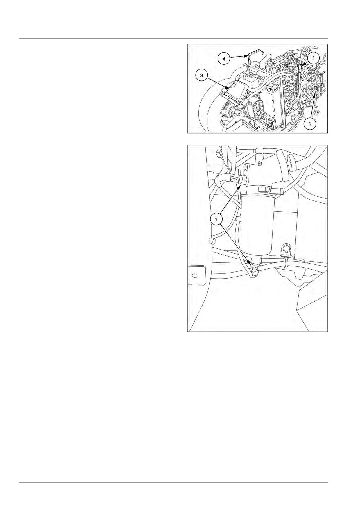
15. Disconnect all electrical connections that prevent the
engine from being removed from the gearbox trans-
mission housing. For example, the main connections
(1), the main cab and power connections (2), the en-
gine control unit connections (3), the fuse box (4), the
sensors, and the extensions, depending on the tractor
model.
MOIL13TR02889AB
15
16. Remove the electrical connections (1) on the fuel filter.
ANIL18TRO1170AA
16
51553302 19/11/2018
10.1 [10.001] / 8
Engine - Engine and crankcase
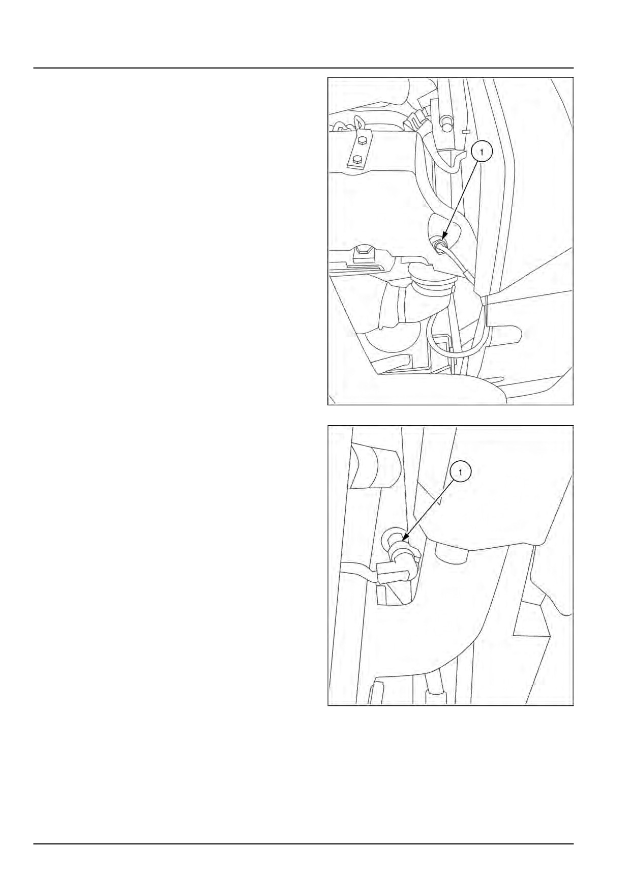
17. Remove the electrical connections (1) on the fuel
pump
ANIL18TRO1171AA
17
18. Remove main electrical connection (1).
ANIL18TRO1172AA
18
51553302 19/11/2018
10.1 [10.001] / 9
Engine - Engine and crankcase
19. Remove the electrical connections (1) on the EGR
valve and suction line.
ANIL18TRO1173AA
19
20. Remove the electrical connection (1) on the brake oil
reservoir
ANIL18TRO1089AA
20
51553302 19/11/2018
10.1 [10.001] / 10
Engine - Engine and crankcase
21. Remove the electrical connection (1) on the Waste-
gate actuator.
ANIL18TRO1174AA
21
22. Remove the oil pipes (1) on right hand side of the front
panel
ANIL18TRO1175AA
22
51553302 19/11/2018
10.1 [10.001] / 11
Engine - Engine and crankcase
23. Remove the electrical connections (1) on fuel filter
ANIL18TRO1176AA
23
ANIL18TRO1177AA
24
51553302 19/11/2018
10.1 [10.001] / 12
Engine - Engine and crankcase
24. Remove the electrical connection (1) of the engine
fuse panel.
ANIL18TRO1178AA
25
25. Remove the electrical connections (1) on each fuel
injector
ANIL18TRO1180AA
26
51553302 19/11/2018
10.1 [10.001] / 13
Engine - Engine and crankcase
26. Remove the electrical connections (1) between en-
gine and front panel
ANIL18TRO1182AA
27
27. Remove the crank shaft sensor (1) and cam shaft sen-
sor (2)
ANIL18TRO1183AA
28
51553302 19/11/2018
10.1 [10.001] / 14
Engine - Engine and crankcase
28. Remove the electrical connections on the alternator
(1) .
ANIL18TRO1184AA
29
29. Remove the engine vent pipe (1) .
ANIL18TRO1185AA
30
51553302 19/11/2018
10.1 [10.001] / 15
Engine - Engine and crankcase
30. Remove the NOx sensor (1) on the DOC
ANIL18TRO1186AA
31
31. Remove engine oil pressure sensor (1)
ANIL18TRO1187AA
32
51553302 19/11/2018
10.1 [10.001] / 16
Engine - Engine and crankcase
32. Remove fuel pipe (1) from fuel tank
ANIL18TRO1188AA
33
33. Remove coolant pipe (1) form engine
ANIL18TRO1189AA
34
51553302 19/11/2018
10.1 [10.001] / 17
Engine - Engine and crankcase
34. Remove exhaust pipe (1) from DOC
ANIL18TRO1190AA
35
35. Remove the retaining bolts (1). Remove the top ra-
diator guard (2). Remove all the remaining free wire
bundles.
MOIL13TR02942AA
36
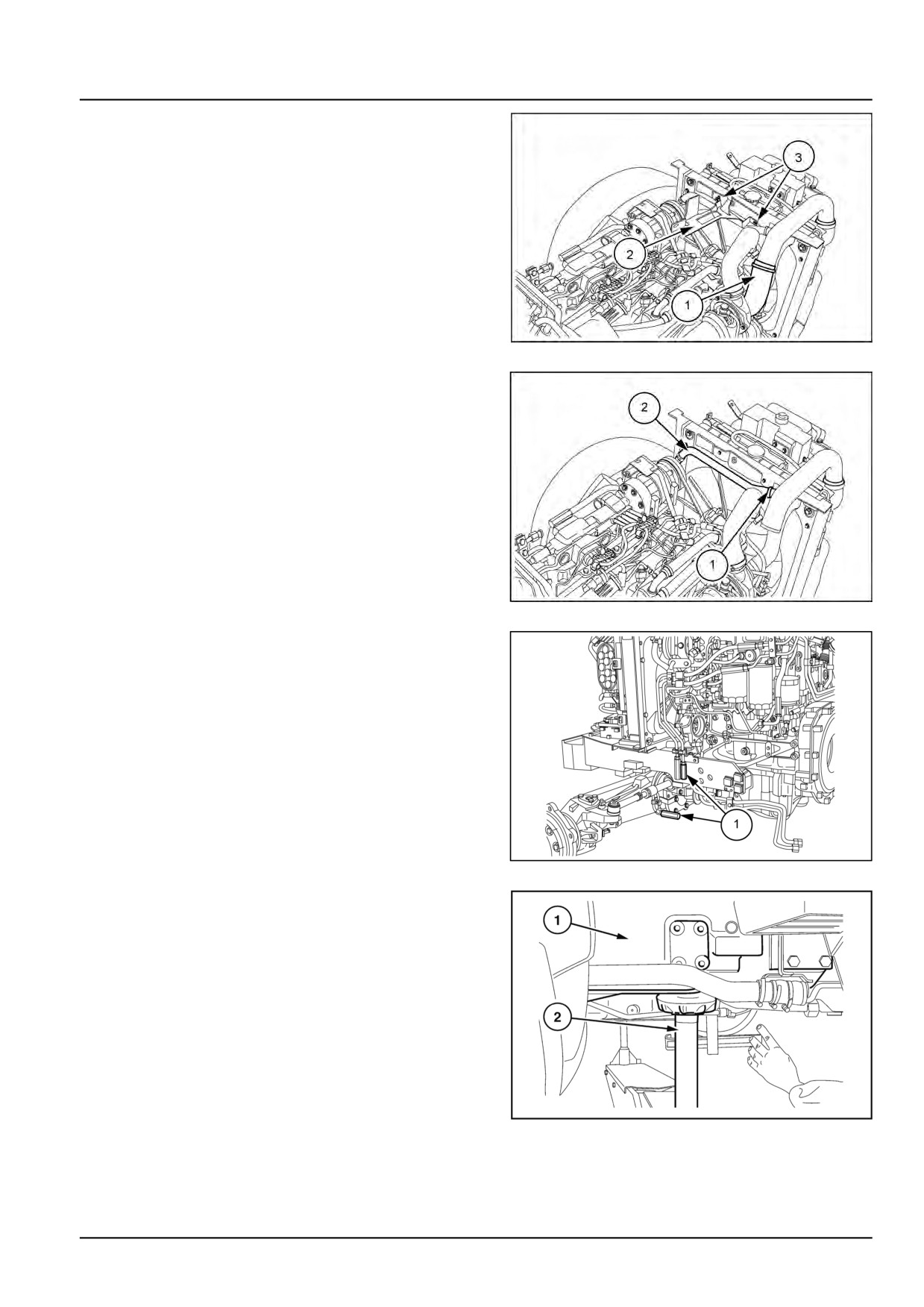
36. Loosen the strip on the inlet of the hose (1) that feeds
fluid to the radiator. Disconnect the hose. Drain the
engine radiator fluid and refill with fluid.
37. Remove the retaining strip. Hose (2) that returns the
radiator fluid to the engine.
MOIL13TR02877AB
37
51553302 19/11/2018
10.1 [10.001] / 18
Engine - Engine and crankcase
38. Loosen the strip. Disconnect the hose (1) that runs
from the air filter to the turbine. Next, remove the two
bolts (3) and remove the bracket (2).
MOIL13TR02890AB
38
39. Loosen the strip (1). Remove the hose (2) that con-
nects the air filter to the injection pump. .
MOIL13TR02891AB
39
40. Disconnect the hydraulic steering hoses (1). Discon-
nect the lines from the axle bracket. .
MOIL13TR02881AB
40
41. Attach chains or ropes to the lifting and eye bolts be-
hind the engine and attach to a winch. Place a fixed
lifting jack (2) under the clutch body (1) next to the en-
gine retaining flange. Apply the handbrake.
WLAPL4S10C129A
41
51553302 19/11/2018
10.1 [10.001] / 19
Engine - Engine and crankcase
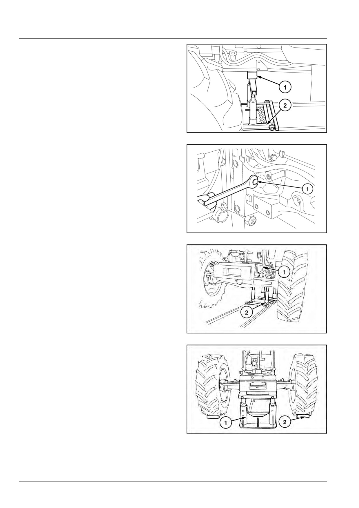
42. Place the moving tractor separator tool (2) under the
engine with the mounting bracket and the adapter
plate. Place a wooden block (1) at the points of con-
tact between the tool and the motor. Chock the axle
to prevent the axle from shaking. 380000405.
WLAPL4S10C140A
42
43. Remove the retaining bolts (1) between the engine
and the transmission.
WLAPL4S10C130A
43
44. Separate the engine from the transmission with tool
380000405
(2).
380000405.
WLAPL4S10C131AA
44
45. Place the fixed lifting jack (1) under the additional
weight support. Use wooden blocks (2) to secure the
front wheels. .
WLAPL4S10C132AA
45
51553302 19/11/2018
10.1 [10.001] / 20
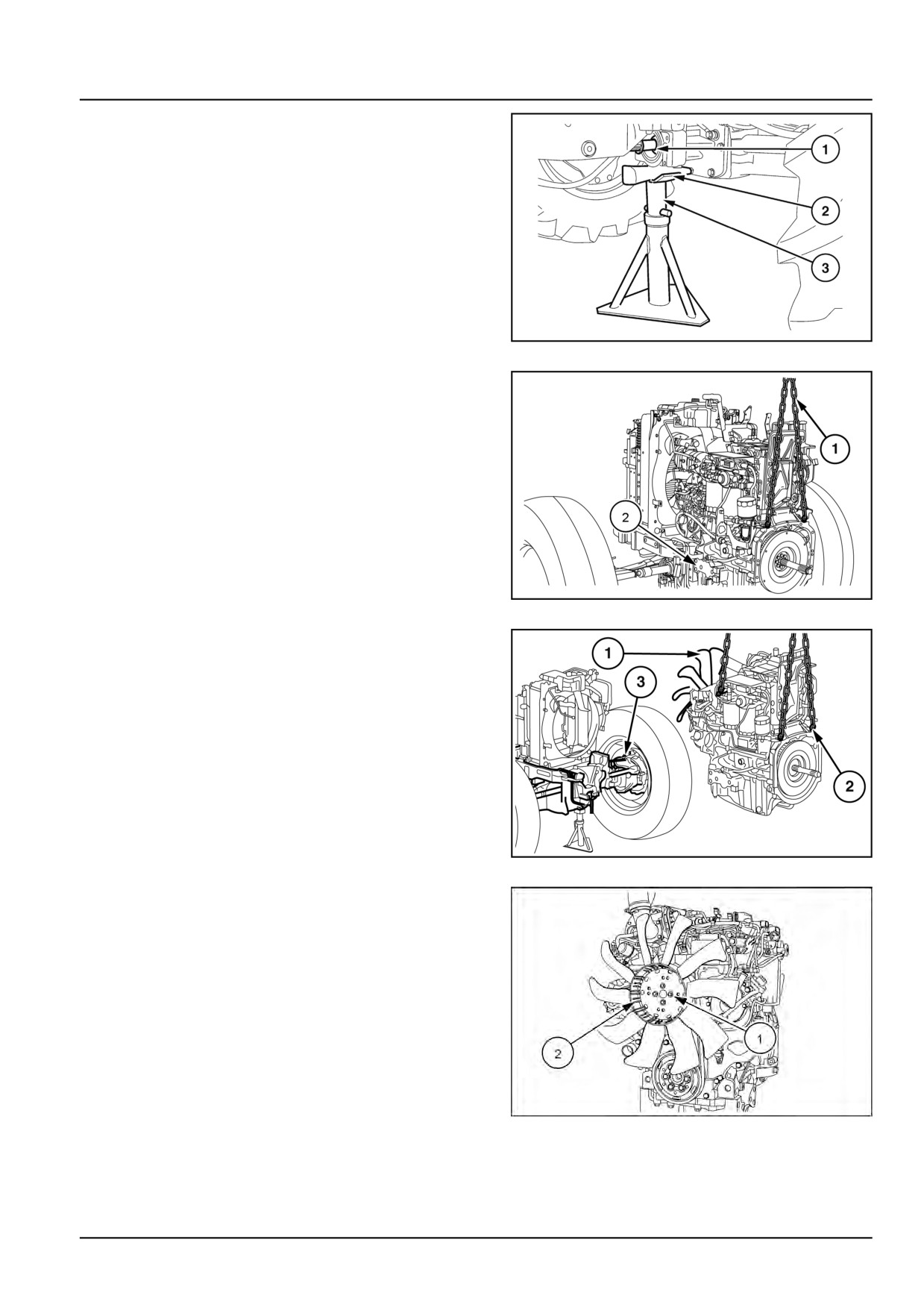
Engine - Engine and crankcase
46. Place a wooden stop between parts (3) and (1). Place
a fixed lifting jack (3) under the front axle drive groove
(1) bracket.
WLAPL4S10C133A
46
47. With the connection assembly firmly secure, place a
lifting jack at the rear of the engine to leave slack in
the winch.
Add a rope or chain to the front of the engine (1).
Keep the engine balanced and take the slack out of
the lifting assembly.
48. Remove the bolts that secure the front axle bracket to
the engine (2).
WLAPL4S10C136A
47
49. Check that there is no elbow between the engine and
the radiator. Separate the engine (2) from the axle
(3). To prevent damage to the fins of the radiator on
the engine ventilator (1) axle, try to avoid incorrect
manoeuvres with the winch. Lower the engine (2) onto
a support bracket.
WLAPL4S10C138A
48
50. Loosen the four bolts (1). Remove the fan (2).
MOIL13TR02885AA
49
51553302 19/11/2018
10.1 [10.001] / 21