New Holland BoomerTM 20 / BoomerTM 25 Compact Tractor. SERVICE MANUAL (2016)
SERVICE MANUAL
Boomer
TM 20 / Boomer
TM 25
Compact Tractor
Part number 48017684
English
June 2016
SERVICE MANUAL
Boomer™ 20
Boomer™ 25
48017684 02/06/2016
EN
Link Product / Engine
Product
Market Product
Engine
Boomer™ 20
Europe
S3L2
Boomer™ 25
Europe
S3L2
4801768402/06/2016
Contents
INTRODUCTION
Engine
10
[10.001] Engine and crankcase
10.1
[10.304] Engine lubrication system
10.2
[10.400] Engine cooling system
10.3
Clutch
18
[18.110] Clutch and components
18.1
[18.112] Slip clutch or flywheel damper
18.2
Transmission
21
[21.114] Mechanical transmission
21.1
Front axle system
25
[25.100] Powered front axle
25.1
[25.102] Front bevel gear set and differential
25.2
[25.108] Final drive hub, steering knuckles, and shafts
25.3
[25.310] Final drives
25.4
Rear axle system
27
[27.106] Rear bevel gear set and differential
27.1
[27.124] Final drive hub, steering knuckles, and shafts
27.2
Hydrostatic drive
29
[29.100] Transmission and steering hydrostatic control
29.1
[29.202] Hydrostatic transmission
29.2
[29.204] Reservoir, cooler, and lines
29.3
[29.218] Pump and motor components
29.4
Power Take-Off (PTO)
31
[31.101] Rear mechanical control
31.1
[31.104] Rear electro-hydraulic control
31.2
4801768402/06/2016
[31.110] One-speed rear Power Take-Off (PTO)
31.3
[31.120] Central Power Take-Off (PTO)
31.4
Brakes and controls
33
[33.110] Parking brake or parking lock
33.1
[33.120] Mechanical service brakes
33.2
Hydraulic systems
35
[35.000] Hydraulic systems
35.1
[35.104] Fixed displacement pump
35.2
[35.114] Three-point hitch control valve
35.3
[35.116] Three-point hitch cylinder
35.4
[35.204] Remote control valves
35.5
[35.300] Reservoir, cooler, and filters
35.6
[35.350] Safety and main relief valves
35.7
Hitches, drawbars, and implement couplings
37
[37.110] Rear three-point hitch
37.1
Steering
41
[41.106] Tie rods
41.1
[41.200] Hydraulic control components
41.2
[41.216] Cylinders
41.3
Wheels
44
[44.511] Front wheels
44.1
[44.520] Rear wheels
44.2
Electrical systems
55
[55.000] Electrical system
55.1
[55.010] Fuel injection system
55.2
[55.011] Fuel tank system
55.3
[55.012] Engine cooling system
55.4
4801768402/06/2016
[55.013] Engine oil system
55.5
[55.031] Parking brake electrical system
55.6
[55.048] Rear Power Take-Off (PTO) control system
55.7
[55.100] Harnesses and connectors
55.8
[55.201] Engine starting system
55.9
[55.202] Cold start aid
55.10
[55.302] Battery
55.11
[55.404] External lighting
55.12
[55.405] External lighting switches and relays
55.13
[55.408] Warning indicators, alarms, and instruments
55.14
Platform, cab, bodywork, and decals
90
[90.120] Mechanically-adjusted operator seat
90.1
4801768402/06/2016
Contents
INTRODUCTION
Foreword
3
Foreword - Important notice regarding equipment servicing
4
International symbols
5
Safety rules
6
Safety rules
7
Safety rules - Ecology and the environment
8
Basic instructions hardware
9
Torque - Standard torque data for hydraulic connections
10
Basic instructions - Shop and assembly
17
General specification - Tractors with Hydrostatic Transmission (HST)
19
General specification - Tractor with mechanical transmission
23
General specification
26
Dimension
27
Consumables
30
Capacities
31
Product identification
32
Product identification machine orientation
34
48017684 02/06/2016
2
INTRODUCTION
Foreword
This repair manual provides the technical information needed to properly service the NEW HOLLAND models Boomer
20 and 25 tractors. Use this manual in conjunction with the operator's manual for complete operation, adjustment,
and maintenance information
On NEW HOLLAND equipment, left and right are determined by standing behind the unit, looking in the direction of
travel.
48017684 02/06/2016
3
INTRODUCTION
Foreword - Important notice regarding equipment servicing
All repair and maintenance work listed in this manual must be carried out only by qualified dealership personnel,
strictly complying with the instructions given, and using, whenever possible, the special tools.
Anyone who performs repair and maintenance operations without complying with the procedures provided herein
shall be responsible for any subsequent damages.
The manufacturer and all the organizations of its distribution chain, including - without limitation - national, regional, or
local dealers, reject any responsibility for damages caused by parts and/or components not approved by the manu-
facturer, including those used for the servicing or repair of the product manufactured or marketed by the manufacturer.
In any case, no warranty is given or attributed on the product manufactured or marketed by the manufacturer in case
of damages caused by parts and/or components not approved by the manufacturer.
The manufacturer reserves the right to make improvements in design and changes in specifications at any time without
notice and without incurring any obligation to install them on units previously sold. Specifications, descriptions, and
illustrative material herein are as accurate as known at time of publication but are subject to change without notice.
In case of questions, refer to your NEW HOLLAND Sales and Service Networks.
48017684 02/06/2016
4
INTRODUCTION
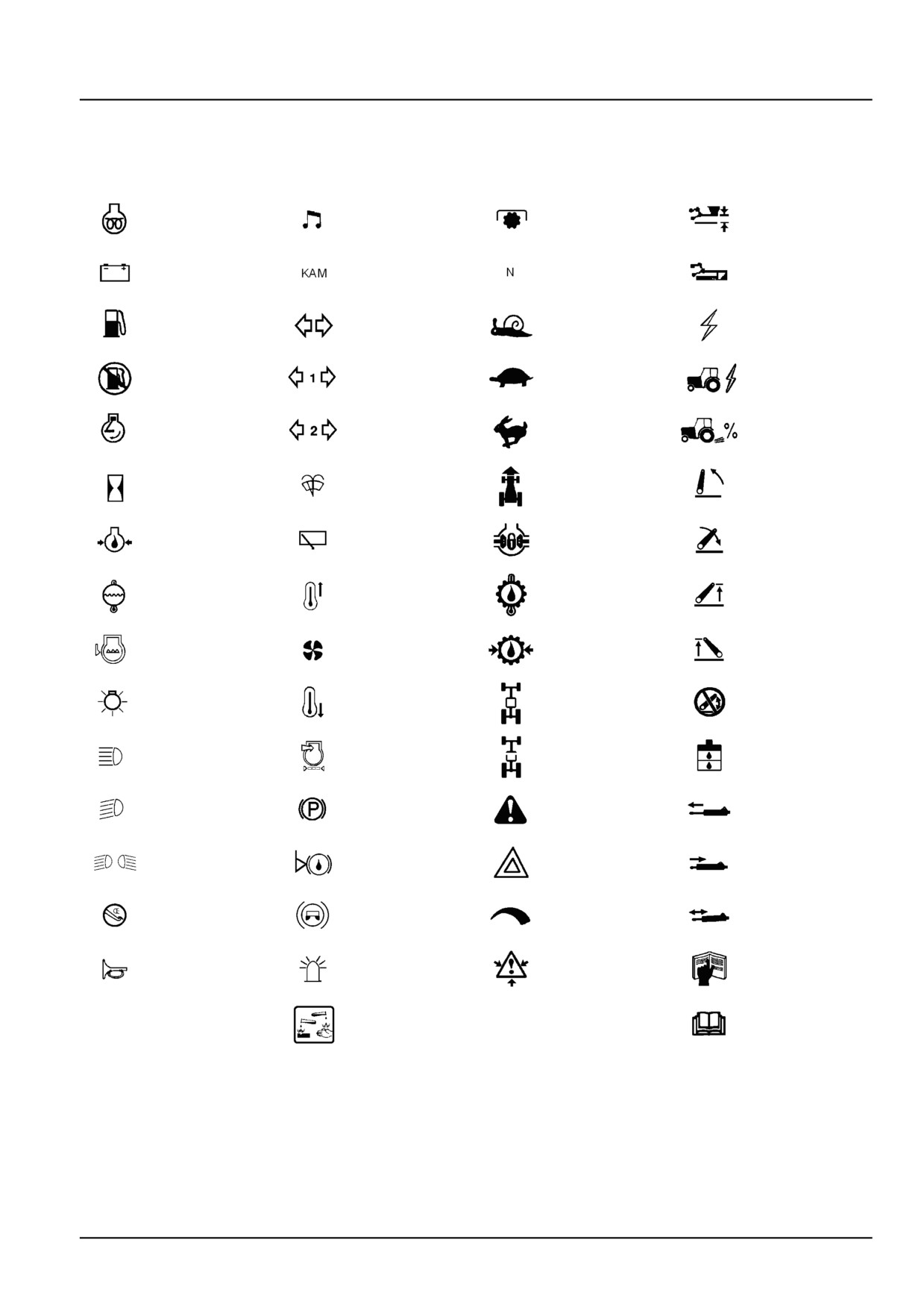
International symbols
As a guide to the operation of the machine, various universal symbols have been utilized on the instruments, controls,
switches, and fuse box. The symbols are shown below with an indication of their meaning.
Thermostart
Position
Radio
PTO
starting aid
Control
Alternator
Keep alive
Transmission
Draft
charge
memory
in neutral
Control
Creeper
Accessory
Fuel level
Turn signals
gears
socket
Automatic
Turn signals
Slow or
Implement
Fuel shut-off
-one trailer
low setting
socket
Engine speed
Turn signals
Fast or high
%age
( RPM x 100)
-two trailers
setting
slip
Front wind-
Ground
Hitch raise
Hours recorded
screen
speed
(rear)
wash/wipe
Rear wind-
Engine oil
Differential
Hitch lower
screen
pressure
lock
(rear)
wash/wipe
Rear axle
Engine coolant
Heater temp-
Hitch height
oil tem-
temperature
erature control
limit (rear)
perature
Coolant
Transmission
Hitch height
Heater fan
level
oil pressure
limit (front)
FWD
Hitch dis-
Tractor lights
Air conditioner
engaged
abled
Hydraulic and
Headlamp
Air filter
FWD dis-
transmission
main beam
blocked
engaged
filters
Headlamp
Parking
Remote
Warning!
dipped beam
brake
valve extend
Brake fluid
Hazard
Remote
Work lamps
level
warning lights
valve retract
Stop
Trailer
Variable
Remote
lamps
brake
control
valve float
Malfunction!
Roof
Pressurised!
Horn
See Operator's
beacon
Open carefully
Manual
Warning !
Malfunction!
Corrosive
(alter-
substance
native symbol)
48017684 02/06/2016
5
INTRODUCTION
Safety rules
BT09A213
1
48017684 02/06/2016
6
INTRODUCTION
Safety rules
Personal safety
This is the safety alert symbol. It is used to alert you to potential personal injury hazards. Obey all
safety messages that follow this symbol to avoid possible death or injury.
Throughout this manual you will find the signal words DANGER, WARNING, and CAUTION followed by special in-
structions. These precautions are intended for the personal safety of you and those working with you.
Read and understand all the safety messages in this manual before you operate or service the machine.
DANGER indicates a hazardous situation that, if not avoided, will result in death or serious injury.
WARNING indicates a hazardous situation that, if not avoided, could result in death or serious injury.
CAUTION indicates a hazardous situation that, if not avoided, could result in minor or moderate injury.
FAILURE TO FOLLOW DANGER, WARNING, AND CAUTION MESSAGES COULD RESULT
IN DEATH OR SERIOUS INJURY.
Machine safety
NOTICE: Notice indicates a situation that, if not avoided, could result in machine or property damage.
Throughout this manual you will find the signal word Notice followed by special instructions to prevent machine or
property damage. The word Notice is used to address practices not related to personal safety.
Information
NOTE: Note indicates additional information that clarifies steps, procedures, or other information in this manual.
Throughout this manual you will find the word Note followed by additional information about a step, procedure, or
other information in the manual. The word Note is not intended to address personal safety or property damage.
48017684 02/06/2016
7
INTRODUCTION
Safety rules - Ecology and the environment
Soil, air, and water quality is important for all industries and life in general. When legislation does not yet rule the
treatment of some of the substances that advanced technology requires, sound judgment should govern the use and
disposal of products of a chemical and petrochemical nature.
Familiarize yourself with the relative legislation applicable to your country, and make sure that you understand this
legislation. Where no legislation exists, obtain information from suppliers of oils, filters, batteries, fuels, anti-freeze,
cleaning agents, etc., with regard to the effect of these substances on man and nature and how to safely store, use,
and dispose of these substances.
Helpful hints
• Avoid the use of cans or other inappropriate pressurized fuel delivery systems to fill tanks. Such delivery systems
may cause considerable spillage.
• In general, avoid skin contact with all fuels, oils, acids, solvents, etc. Most of these products contain substances
that may be harmful to your health.
• Modern oils contain additives. Do not burn contaminated fuels and or waste oils in ordinary heating systems.
• Avoid spillage when you drain fluids such as used engine coolant mixtures, engine oil, hydraulic fluid, brake fluid,
etc. Do not mix drained brake fluids or fuels with lubricants. Store all drained fluids safely until you can dispose of
the fluids in a proper way that complies with all local legislation and available resources.
• Do not allow coolant mixtures to get into the soil. Collect and dispose of coolant mixtures properly.
• The air-conditioning system contains gases that should not be released into the atmosphere. Consult an air-condi-
tioning specialist or use a special extractor to recharge the system properly.
• Repair any leaks or defects in the engine cooling system or hydraulic system immediately.
• Do not increase the pressure in a pressurized circuit as this may lead to a component failure.
• Protect hoses during welding. Penetrating weld splatter may burn a hole or weaken hoses, allowing the loss of oils,
coolant, etc.
Battery recycling
Batteries and electric accumulators contain several substances that can have a harmful
effect on the environment if the batteries are not properly recycled after use. Improper
disposal of batteries can contaminate the soil, groundwater, and waterways. NEW
HOLLAND strongly recommends that you return all used batteries to a NEW HOLLAND
dealer, who will dispose of the used batteries or recycle the used batteries properly. In
some countries, this is a legal requirement.
Mandatory battery recycling
NOTE: The following requirements are mandatory in Brazil.
Batteries are made of lead plates and a sulfuric acid solution. Because batteries contain heavy metals such as lead,
CONAMA Resolution 401/2008 requires you to return all used batteries to the battery dealer when you replace any
batteries. Do not dispose of batteries in your household garbage.
Points of sale are obliged to:
• Accept the return of your used batteries
• Store the returned batteries in a suitable location
• Send the returned batteries to the battery manufacturer for recycling
48017684 02/06/2016
8
INTRODUCTION
Basic instructions hardware
General
Your tractor has been built using metric hardware.
NOTE: Be sure to use the hardware specified when using tapped holes, as trying to install a metric bolt in an inch
thread, or an inch bolt in a metric thread, will damage the thread.
Certain hardware must be tightened to specific torque specifications. If specific torque specifications are not noted,
tighten the hardware to the standard torque chart specification listed in this manual.
Plating
Hardware used on NEW HOLLAND balers is plated with zinc chromate (gold color). Gold colored hardware has
different torquing requirements from unplated or zinc plated (silver color) hardware because of the difference in the
coefficient of friction of the plating material. The torque charts in this manual list the correct specifications for gold,
silver, and unplated bolts.
Nut tightening
Whenever possible, the nut should be tightened, not the head of the bolt. When tightening using the bolt head, the
clamp load can be lost because some of the torque applied twists the bolt instead of tensioning (stretching) it. The
tension on the bolt is what holds the joint together.
Approximately 90% of the torque applied during assembly goes to overcoming friction between the parts. The other
10% is used to tension (stretch) the bolt. After assembly, the frictional forces disappear, which is the basis for the
saying 'If it does not fail during assembly, it will not fail in service.' The bolt may later fail due to other factors, but not
from being over tightened.
Locknuts
Most locknuts are coated with a special lubricant that is dry to the touch. Anytime a locknut is used, a lower than
normal torque is required. Refer to the torque charts in this manual for specific values.
Jam nuts
When using a jam nut to lock a regular nut, the jam nut should be installed first and tightened to one half the recom-
mended torque, then held in place while installing a regular nut to the recommended torque.
Thread lubrication
The addition of antiseize compound, Molykote, oil, graphite, or any other lubricant to a bolt decreases the friction
between it and a nut. This makes it necessary to reduce the recommended torque to prevent over tensioning of the
bolt. When using the torque charts in this manual, decrease the value by 20% whenever a lubricant is used.
48017684 02/06/2016
9
INTRODUCTION
Torque - Standard torque data for hydraulic connections
General information
• Hydraulic connections require a minimum assembly torque in order to provide zero leakage at rated pressure with
adequate fatigue resistance. Over-torquing of a hydraulic connection can also lead to leakage or failure. For some
connections, NEW HOLLAND requires a different torque value than is listed in the ISO and SAE standards.
• The torque values in this document should be used whenever possible or applicable.
NOTICE: Always follow the instructions in this manual for specific torque values when you service components.
The information in this section is for general guidance only when a procedure contains no specific torque value.
Tolerance
• The tolerance for all torque values is ± 10 %. This tolerance must include all assembly variation, not only the torque
wrench repeatability.
Lubrication
Application of grease or other lubricants to hydraulic connectors should be avoided. If clean hydraulic oil is already
on the connection, it is not required to remove the oil. Generally, application of grease:
• May cause a significant change in the torque required to properly tighten the connection.
• May reduce the connection’s resistance to vibration.
• Excessive grease may displace an elastomer seal during tightening.
• Grease extrusion when connection is tightened may be mistaken for leakage.
NEW HOLLAND products generally use O-Ring Boss (ORB) connectors that have Teflon™-coated O-rings, eliminat-
ing the need for O-ring lubrication during installation. For connections which are made into aluminum manifolds or
with stainless steel connectors, it may be required to apply a lubricant to prevent galling.
Use of LOCTITE® and other thread-locking compounds is prohibited. These compounds:
• May cause a significant change in the torque required to properly tighten the connections.
• Reduce the serviceability of the joint.
• May prevent the O-ring from properly sealing if the compound gets on the O-ring.
48017684 02/06/2016
10
INTRODUCTION
Torque values for metric O-Ring Boss (ORB) port connections
S-Series *
L-Series **
Metric
Ferrous
Non-Ferrous
Ferrous
Non-Ferrous
thread
N·m (lb ft) ± 10 %
N·m (lb ft) ± 10 %
N·m (lb ft) ± 10 %
N·m (lb ft) ± 10
%
M8 x 1
10.5
(7.7)
6.3
(4.6)
8.5
(6.3)
5
(3.7)
M10 x 1
21
(15.5)
12.5
(9.2)
15.5
(11.4)
9.3
(6.9)
M12 x 1.5
37
(27.3)
22
(16.2)
27
(19.9)
16
(11.8)
M14 x 1.5
47
(34.7)
28
(20.7)
37
(27.3)
22
(16.2)
M16 x 1.5
58
(42.8)
35
(25.8)
42
(31)
25
(18.4)
M18 x 1.5
74
(54.6)
44
(32.5)
47
(34.7)
28
(20.7)
M22 x 1.5
105
(77.4)
63
(46.5)
63
(46.5)
38
(28)
M27 x 2
178
(131.3)
107
(78.9)
105
(77.4)
63
(46.5)
M30 x 2
225
(166)
135
(99.6)
136
(100.3)
82
(60.5)
M33 x 2
325
(239.7)
195
(143.8)
168
(123.9)
101
(74.5)
M42 x 2
345
(254.5)
207
(152.7)
220
(162.3)
132
(97.4)
M48 x 2
440
(324.5)
264
(194.7)
273
(201.4)
164
(121)
M60 x 2
525
(387.2)
315
(232.3)
330
(243.4)
198
(146)
* S-Series connectors are used with O-Ring Face Seals (ORFS).
** L-Series connectors are used with 37 ° flare.
Torque values for metric O-Ring Boss (ORB) port plugs
Ferrous
Non-ferrous
Metric
Internal hex
External hex
N·m (lb ft) ± 10 %
thread
N·m (lb ft) ± 10 %
N·m (lb ft) ± 10 %
M8 x 1
8.5
(6.3)
10.5
(7.7)
6.3
(4.6)
M10 x 1
16
(11.8)
21
(15.5)
12.5
(9.2)
M12 x 1.5
23
(17)
37
(27.3)
22
(16.2)
M14 x 1.5
47
(34.7)
47
(34.7)
28
(20.7)
M16 x 1.5
58
(42.8)
58
(42.8)
35
(25.8)
M18 x 1.5
74
(54.6)
74
(54.6)
44
(32.5)
M22 x 1.5
105
(77.4)
105
(77.4)
63
(46.5)
M27 x 2
178
(131.3)
178
(131.3)
107
(78.9)
M30 x 2
225
(166)
225
(166)
135
(99.6)
M33 x 2
325
(239.7)
325
(239.7)
195
(143.8)
M42 x 2
345
(254.5)
345
(254.5)
207
(152.7)
M48 x 2
440
(324.5)
440
(324.5)
264
(194.7)
M60 x 2
525
(387.2)
525
(387.2)
315
(232.3)
48017684 02/06/2016
11
INTRODUCTION
Torque values for port connections (British Standard Pipe Parallel (BSPP) thread ports and stud ends)
Metric tube
Outside Diameter (OD)
Ferrous
Non-Ferrous
mm (in)
BSPP
S-Series
L-Series
S-Series
L-Series
thread
G- Gas;
S-Series *
L-Series **
N·m (lb ft)
N·m (lb ft)
N·m (lb ft)
N·m (lb ft)
A- medium
± 10 %
± 10 %
± 10 %
± 10 %
coarse threads
G 1/8 A
-
6
(0.236)
-
21
(15.5)
-
12.5
(9.2)
6
(0.236)
8
(0.315)
G 1/4 A
or
or
63
(46.5)
53
(39.1)
38
(28)
32
(23.6)
8
(0.315)
10
(0.394)
10
(0.394)
G 3/8 A
or
12
(0.472)
95
(70.1)
84
(62)
57
(42)
50
(36.9)
12
(0.472)
15
(0.591)
G 1/2 A
16
(0.630)
or
136
(100.3)
105
(77.4)
82
(60.5)
63
(46.5)
18
(0.709)
G 3/4 A
20
(0.787)
22
(0.866)
210
(154.9)
210
(154.9)
126
(92.9)
126
(92.9)
G1A
25
(0.984)
28
(1.102)
400
(295)
400
(295)
240
(177)
240
(177)
G 1 1/4 A
30
(1.181)
35
(1.378)
525
(387.2)
525
(387.2)
315
(232.3)
315
(232.3)
G 1 1/2 A
38
(1.496)
42
(1.654)
660
(486.8)
660
(486.8)
396
(292.1)
396
(292.1)
* S-Series connectors are used with O-Ring Face Seals (ORFS).
** L-Series connectors are used with 37 ° flare.
Torque values for metric port connections (Metric face-seal ports and stud ends)
Metric tube
Outside Diameter (OD)
Ferrous
Non-Ferrous
mm (in)
S-Series
L-Series
S-Series
L-Series
Metric
S-Series *
L-Series **
N·m (lb ft)
N·m (lb ft)
N·m (lb ft)
N·m (lb ft)
thread
± 10 %
± 10 %
± 10 %
± 10 %
M10 x 1
-
4
(0.157)
-
21
(15.5)
-
12.5
(9.2)
M12 x 1.5
4
(0.157)
6
(0.236)
47
(34.7)
32
(23.6)
28
(20.7)
19
(14)
M14 x 1.5
5
(0.197)
7
(0.276)
63
(46.5)
53
(39.1)
38
(28)
32
(23.6)
M16 x 1.5
7
(0.276)
9
(0.354)
84
(62)
63
(46.5)
50
(36.9)
38
(28)
M18 x 1.5
8
(0.315)
11
(0.433)
105
(77.4)
84
(62)
63
(46.5)
50
(36.9)
M20 x 1.5
10
(0.394)
-
147
(108.4)
-
88
(64.9)
-
M22 x 1.5
12
(0.472)
14
(0.551)
158
(116.5)
147
(108.4)
95
(70.1)
88
(64.9)
M26 x 1.5
-
18
(0.709)
-
210
(154.9)
-
126
(92.9)
M27 x 1.2
16
(0.630)
-
210
(154.9)
126
(92.9)
-
M33 x 2
20
(0.787)
23
(0.906)
400
(295)
400
(295)
240
(177)
240
(177)
M42 x 2
25
(0.984)
30
(1.181)
525
(387.2)
525
(387.2)
315
(232.3)
315
(232.3)
M48 x 2
32
(1.260)
36
(1.417)
630
(464.7)
630
(464.7)
396
(292.1)
396
(292.1)
* S-Series connectors are used with O-Ring Face Seals (ORFS).
** L-Series connectors are used with 37 ° flare.
48017684 02/06/2016
12
INTRODUCTION
Torque values for Inch O-Ring Boss (ORB) port non-adjustable connections
S-Series *
L-Series **
Ferrous
Non-
Ferrous
Non-
Inch tube
SAE
UN/UNF
N·m (lb ft)
Ferrous
N·m (lb ft)
Ferrous
OD
dash size
thread size
± 10 %
N·m (lb ft)
± 10 %
N·m (lb ft)
mm (in)
± 10 %
± 10 %
2
5/16-24
3.18
(0.125)
-
-
8.5
(6.3)
5
(3.7)
3
3/8-24
4.76
(0.187)
15.5
(11.4)
9.3
(6.9)
10.5
(7.7)
6.3
(4.6)
4
7/16-20
6.35
(0.250)
37
(27.3)
22
(16.2)
19
(14)
11.5
(8.5)
5
1/2-20
7.94
(0.313)
42
(31)
25
(18.4)
26
(19.2)
15.5
(11.4)
6
9/16-18
9.52
(0.375)
47
(34.7)
28
(20.7)
32
(23.6)
19
(14)
8
3/4-16
12.7
(0.500)
89
(65.6)
53
(39.1)
53
(39.1)
32
(23.6)
10
7/8-14
15.88
(0.625)
121
(89.2)
73
(53.8)
63
(46.5)
38
(28)
12
1-1/16-12
19.05
(0.750)
178
(131.3)
107
(78.9)
100
(73.8)
60
(44.3)
14
1-3/16-12
22.22
(0.875)
225
(166)
135
(99.6)
131
(96.6)
79
(58.3)
16
1-5/16-12
25.4
(1.000)
283
(208.7)
170
(125.4)
156
(115.1)
94
(69.3)
20
1-5/8-12
31.75
(1.250)
300
(221.3)
180
(132.8)
210
(154.9)
126
(92.9)
24
1-7/8-12
38.1
(1.500)
388
(286.2)
233
(171.9)
220
(162.3)
132
(97.4)
32
2-1/2-12
50.8
(2.000)
388
(286.2)
233
(171.9)
315
(232.3)
189
(139.4)
* S-Series connectors are used with O-Ring Face Seals (ORFS).
** L-Series connectors are used with 37 ° flare.
Torque values for inch O-Ring Boss (ORB) port adjustable connections
S-Series *
L-Series **
Ferrous
Non-
Ferrous
Non-
Inch tube
SAE
UN/UNF
N·m (lb ft)
Ferrous
N·m (lb ft)
Ferrous
OD
dash size
thread size
± 10 %
N·m (lb ft)
± 10 %
N·m (lb ft)
mm (in)
± 10 %
± 10 %
2
5/16-24
3.18
(0.125)
-
-
8.5
(6.3)
5
(3.7)
3
3/8-24
4.76
(0.187)
10.5
(7.7)
9.3
(6.9)
10.5
(7.7)
6.3
(4.6)
4
7/16-20
6.35
(0.250)
21
(15.5)
21
(15.5)
19
(14)
11.5
(8.5)
5
1/2-20
7.94
(0.313)
42
(31)
25
(18.4)
26
(19.2)
15.5
(11.4)
6
9/16-18
9.52
(0.375)
47
(34.7)
28
(20.7)
32
(23.6)
19
(14)
8
3/4-16
12.7
(0.500)
89
(65.6)
53
(39.1)
53
(39.1)
32
(23.6)
10
7/8-14
15.88
(0.625)
121
(89.2)
73
(53.8)
63
(46.5)
38
(28)
12
1-1/16-12
19.05
(0.750)
178
(131.3)
107
(78.9)
100
(73.8)
60
(44.3)
14
1-3/16-12
22.22
(0.875)
225
(166)
135
(99.6)
131
(96.6)
79
(58.3)
16
1-5/16-12
25.4
(1.000)
285
(210.2)
170
(125.4)
156
(115.1)
94
(69.3)
20
1-5/8-12
31.75
(1.250)
300
(221.3)
180
(132.8)
210
(154.9)
126
(92.9)
24
1-7/8-12
38.1
(1.500)
388
(286.2)
233
(171.9)
220
(162.3)
132
(97.4)
32
2-1/2-12
50.8
(2.000)
388
(286.2)
233
(171.9)
315
(232.3)
189
(139.4)
* S-Series connectors are used with O-Ring Face Seals (ORFS).
** L-Series connectors are used with 37 ° flare.
48017684 02/06/2016
13
INTRODUCTION
Torque values for inch O-Ring Boss (ORB) port plugs
Ferrous
Non-Ferrous
Internal hex
External hex
SAE
UN/UNF
N·m (lb ft)
N·m (lb ft)
N·m (lb ft)
dash size
thread size
± 10 %
± 10 %
± 10 %
2
5/16-24
7.5
(5.5)
12.5
(9.2)
7.5
(5.5)
3
3/8-24
14.5
(10.7)
21
(15.5)
12.5
(9.2)
4
7/16-20
21
(15.5)
37
(27.3)
22
(16.2)
5
1/2-20
28
(20.7)
42
(31)
25
(18.4)
6
9/16-18
47
(34.7)
47
(34.7)
28
(20.7)
8
3/4-16
89
(65.6)
89
(65.6)
53
(39.1)
10
7/8-14
116
(85.6)
116
(85.6)
70
(51.6)
12
1-1/16-12
176
(129.8)
176
(129.8)
106
(78.2)
14
1-3/16-12
247
(182.2)
247
(182.2)
148
(109.2)
16
1-5/16-12
284
(209.5)
284
(209.5)
170
(125.4)
20
1-5/8-12
357
(263.3)
357
(263.3)
214
(157.8)
24
1-7/8-12
441
(325.3)
441
(325.3)
265
(195.5)
32
2-1/2-12
536
(395.3)
536
(395.3)
322
(237.5)
Torque values for four-bolt flange connections (Metric Screws, Class 10.9)
Code 61
Code 62
Metric size
Imperial size
Screw code
Screw code
N·m (lb ft)
N·m (lb ft)
mm
in
61
62
± 10 %
± 10 %
13
1/2
M8 x 1.25
34
(25.1)
M8 x 1.25
34
(25.1)
19
3/4
M10 x 1.5
74
(54.6)
M10 x 1.5
74
(54.6)
25
1
M10 x 1.5
74
(54.6)
M12 x 1.75
137
(101)
M12 x 1.75
137
(101)
32
1-1/4
M10 x 1.5
74
(54.6)
M14 x 1.5
189
(139.4)
38
1-1/2
M12 x 1.75
137
(101)
M16 x 2
310
(228.6)
51
2
M12 x 1.75
137
(101)
M20 x 2.5
575
(424.1)
64
2-1/2
M12 x 1.75
137
(101)
M24 x 3
575
(424.1)
76
3
M16 x 2
310
(228.6)
M30 x 3.5
680
(501.5)
89
3-1/2
M16 x 2
310
(228.6)
-
-
102
4
M16 x 2
310
(228.6)
-
-
127
5
M16 x 2
310
(228.6)
-
-
Torque values for four-bolt flange connections (Metric Screws, Class 8.8)
Code 61
Code 62
Metric size
Imperial size
Screw code
Screw code
N·m (lb ft)
N·m (lb ft)
mm
in
61
62
± 10 %
± 10 %
13
1/2
M8 x 1.25
29
(21.4)
M8 x 1.25
29
(21.4)
19
3/4
M10 x 1.5
57(42)
M10 x 1.5
57(42)
25
1
M10 x 1.5
57(42)
M12 x 1.75
100
(73.8)
M12 x 1.75
100
(73.8)
32
1-1/4
M10 x 1.5
57(42)
M14 x 1.5
160
(118)
38
1-1/2
M12 x 1.75
100
(73.8)
M16 x 2
250
(184.4)
51
2
M12 x 1.75
100
(73.8)
M20 x 2.5
500
(368.8)
64
2-1/2
M12 x 1.75
100
(73.8)
M24 x 3
575
(424.1)
76
3
M16 x 2
250
(184.4)
M30 x 3.5
680
(501.5)
89
3-1/2
M16 x 2
250
(184.4)
-
-
102
4
M16 x 2
250
(184.4)
-
-
127
5
M16 x 2
250
(184.4)
-
-
48017684 02/06/2016
14
INTRODUCTION
Torque values for four-bolt flange connections (Inch Screws, Grade 8)
Code 61
Code 62
Metric size
Imperial size
Screw code
Screw code
N·m (lb ft)
N·m (lb ft)
mm
in
61
62
± 10 %
± 10 %
13
1/2
5/16-18
34
(25.1)
5/16-18
34
(25.1)
19
3/4
3/8-16
63
(46.5)
3/8-16
63
(46.5)
25
1
3/8-16
63
(46.5)
7/16-14
97
(71.5)
32
1-1/4
7/16-14
97
(71.5)
1/2-13
158
(116.5)
38
1-1/2
1/2-13
158
(116.5)
5/8-11
310
(228.6)
51
2
1/2-13
158
(116.5)
3/4-10
473
(348.9)
64
2-1/2
1/2-13
158
(116.5)
-
-
76
3
5/8-11
310
(228.6)
-
-
89
3-1/2
5/8-11
310
(228.6)
-
-
102
4
5/8-11
310
(228.6)
-
-
127
5
5/8-11
310
(228.6)
-
-
Tapered thread connection tightening
British Standard Pipe Taper
National Pipe Thread Fuel
Turns from finger tight
(BSPT) thread size (inch)
(NPTF) thread size (inch)
1/8-28
1/8-27
2-3
1/4-19
1/4-18
2-3
3/8-19
3/8-18
2-3
1/2-14
1/2-14
2-3
3/4-14
3/4-14
2-3
1-11
1-11 1/2
1.5
- 2.5
1-1/4-11
1-1/4-11 1/2
1.5
- 2.5
1-1/2-11
1-1/2-11 1/2
1.5
- 2.5
2-11
2-11 1/2
1.5
- 2.5
Torque values for banjo bolt connections (Copper washer style)
Bolt thread (metric)
Hex size (mm)
Torque N·m (lb ft) ± 10 %
M8 x 1.25
13
13
(9.6)
M10 x 1.25
17
16
(11.8)
M12 x 1.5
17
40
(29.5)
M14 x 1.5
19
45
(33.2)
M16 x 1.5
22
48
(35.4)
M18 x 1.5
24
50
(36.9)
M20 x 1.5
27
73
(53.8)
M22 x 1.5
32
73
(53.8)
M24 x 1.5
32
73
(53.8)
48017684 02/06/2016
15
INTRODUCTION
Torque values for O-Ring Face Seals (ORFS) connections
**
Hex size
SAE
Metric
Swivel nut
Swivel nut
UN/UNF
Inch tube
(mm)
dash
tube
torque
torque
thread size
OD (mm)
(Reference
size
OD (mm)
N·m (lb ft)
N·m (lb ft)
only)
± 10 %
± 10 %
4
9/16-18
6.35
6
17
27
(19.9)
27
(19.9)
5
5/8-18
7.94
8
19
34
(25.1)
34
(25.1)
6
11/16-16
9.52
10
22
44
(32.5)
44
(32.5)
8
13/16-16
12.7
12
24
65
(47.9)
65
(47.9)
10
1-14
15.88
16
30
100
(73.8)
100
(73.8)
12
1-3/16-12
19.05
20
36
150
(110.6)
131
(96.6)
14
1-5/16-12
22.23
22
41
163
(120.2)
131
(96.6)
16
1-7/16-12
25.4
25
41
210
(154.9) ***
131
(96.9)
20
1-11/16-12
31.75
30
50
280
(206.5) ***
178
(131.3)
24
2-12
38.1
38
60
375
(276.6) ***
210
(154.9)
* High/Medium-pressure applications > 50 bar (725 psi).
** Low-pressure applications < 50 bar (725 psi).
*** It is recommended to use a four-bolt flange connection instead of O-Ring Face Seals (ORFS) sizes "16" and up.
Torque values for 37 ° flare connections - Joint Industry Council (JIC)
SAE
Metric
UN/UNF
Inch tube
Swivel nut torque
dash
tube
thread size
OD (mm)
N·m (lb ft) ± 10 %
size
OD (mm)
2
5/16-24
-
3.18
8.25
(6.1)
3
3/8-24
-
4.76
11.5
(8.5)
4
7/16-20
6
6.35
15.5
(11.4)
5
1/2-20
8
7.94
20
(14.8)
6
9/16-18
10
9.52
25
(18.4)
8
3/4-16
12
12.7
52
(38.4)
10
7/8-14
16
15.88
81
(59.7)
12
1-1/16-12
20
19.05
112
(82.6)
14
1-3/16-12
-
22.22
133
(98.1)
16
1-5/16-12
25
25.4
155
(114.3)
20
1-5/8-12
30/32
31.75
180
(132.8)
24
1-7/8-12
38
38.1
225
(166)
32
2-1/2-12
50
50.8
348
(256.7)
Torque values for 30 ° flare, 60 ° cone connections
British Standard Pipe
Nominal
Swivel nut torque
Parallel (BSPP)
Hex size (mm)
size (mm)
N·m (lb ft) ± 10 %
thread size
5, 6, 6.3
G 1/4
17
25
(18.4)
8, 9, 10
G 3/8
19
34
(25.1)
12, 12.5
G 1/2
22
64
(47.2)
15, 16, 19
G 3/4
30
132
(97.4)
25
G1
36
196
(144.6)
31.5, 32
G 1-1/4
46
225
(166)
38
G 1-1/2
50
255
(188.1)
50, 51
G2
65
316
(223.1)
48017684 02/06/2016
16
INTRODUCTION
Basic instructions - Shop and assembly
Shimming
For each adjustment operation, select adjusting shims and measure the adjusting shims individually using a microm-
eter, then add up the recorded values. Do not rely on measuring the entire shimming set, which may be incorrect, or
the rated value shown on each shim.
Rotating shaft seals
For correct rotating shaft seal installation, proceed as follows:
1. Before assembly, allow the seal to soak in the oil it will be sealing for at least thirty minutes.
2. Thoroughly clean the shaft and check that the working surface on the shaft is not damaged.
3. Position the sealing lip facing the fluid.
NOTE: With hydrodynamic lips, take into consideration the shaft rotation direction and position the grooves so that
they will move the fluid towards the inner side of the seal.
4. Coat the sealing lip with a thin layer of lubricant (use oil rather than grease). Fill the gap between the sealing lip
and the dust lip on double lip seals with grease.
5. Insert the seal in its seat and press down using a flat punch or seal installation tool. Do not tap the seal with a
hammer or mallet.
6. While you insert the seal, check that the seal is perpendicular to the seat. When the seal settles, make sure that
the seal makes contact with the thrust element, if required.
7. To prevent damage to the seal lip on the shaft, position a protective guard during installation operations.
O-ring seals
Lubricate the O-ring seals before you insert them in the seats. This will prevent the O-ring seals from overturning and
twisting, which would jeopardize sealing efficiency.
Sealing compounds
Apply a sealing compound on the mating surfaces when specified by the procedure. Before you apply the sealing
compound, prepare the surfaces as directed by the product container.
Spare parts
Only use CNH Original Parts or NEW HOLLAND Original Parts.
Only genuine spare parts guarantee the same quality, duration, and safety as original parts, as they are the same
parts that are assembled during standard production. Only CNH Original Parts or NEW HOLLAND Original Parts can
offer this guarantee.
When ordering spare parts, always provide the following information:
• Machine model (commercial name) and Product Identification Number (PIN)
• Part number of the ordered part, which can be found in the parts catalog
48017684 02/06/2016
17
INTRODUCTION
Protecting the electronic and/or electrical systems during charging and welding
To avoid damage to the electronic and/or electrical systems, always observe the following practices:
1. Never make or break any of the charging circuit connections when the engine is running, including the battery
connections.
2. Never short any of the charging components to ground.
3. Always disconnect the ground cable from the battery before arc welding on the machine or on any machine
attachment.
• Position the welder ground clamp as close to the welding area as possible.
• If you weld in close proximity to a computer module, then you should remove the module from the machine.
• Never allow welding cables to lie on, near, or across any electrical wiring or electronic component while you
weld.
4. Always disconnect the negative cable from the battery when charging the battery in the machine with a battery
charger.
NOTICE: If you must weld on the unit, you must disconnect the battery ground cable from the machine battery.
The electronic monitoring system and charging system will be damaged if this is not done.
5. Remove the battery ground cable. Reconnect the cable when you complete welding.
WARNING
Battery acid causes burns. Batteries contain sulfuric acid.
Avoid contact with skin, eyes or clothing. Antidote (external): Flush with water. Antidote (eyes): flush
with water for 15 minutes and seek medical attention immediately. Antidote (internal): Drink large
quantities of water or milk. Do not induce vomiting. Seek medical attention immediately.
Failure to comply could result in death or serious injury.
W0111A
Special tools
The special tools that NEW HOLLAND suggests and illustrate in this manual have been specifically researched and
designed for use with NEW HOLLAND machines. The special tools are essential for reliable repair operations. The
special tools are accurately built and rigorously tested to offer efficient and long-lasting operation.
By using these tools, repair personnel will benefit from:
• Operating in optimal technical conditions
• Obtaining the best results
• Saving time and effort
• Working in safe conditions
48017684 02/06/2016
18

INTRODUCTION
General specification - Tractors with Hydrostatic Transmission
(HST)
Model
Model
Boomer 20 -
Boomer 25 -
Hydrostatic
Hydrostatic
ENGINE
Type
Diesel
Diesel
Model
S3L
S3L2
Engine Gross Horsepower
17 kW (23 Hp)
20 kW (27 Hp)
Cylinders
4
4
Bore
78 mm (3.07 in)
78 mm (3.07 in)
Stroke
78.5 mm (3.09 in)
92 mm (3.62 in)
Displacement
1.125 l (69 in³)
1.318 l (80 in³)
Compression Ratio
22.0:1
20.0:1
Firing Order
1-3-2
1-3-2
Low Idle Speed
970±30 RPM
970±30 RPM
Maximum Speed:
High Idle
29000±20 RPM
2900±20 RPM
Rated
2700 RPM
2700 RPM
Valve Clearance (Cold)
Intake
0.020 - 0.050 mm (0.0008 - 0.0020 in)
0.020 - 0.050 mm (0.0008 - 0.0020 in)
Exhaust
0.050 - 0.085 mm (0.0020 - 0.0033 in)
0.050 - 0.085 mm (0.0020 - 0.0033 in)
CAPACITIES
Fuel Tank
25 l (6.6 US gal)
25 l (6.6 US gal)
Cooling System
3.8 l (1.0 US gal)
3.8 l (1.0 US gal)
Engine Crankcase:
With Filter
4 l (1.10 US gal)
4 l (1.10 US gal)
Rear Axle & Transmission (Includes
Hydraulics)
HST
20 l (5.28 US gal)
20 l (5.28 US gal)
Front Axle
3 l (1 US gal)
3 l (1 US gal)
COOLING SYSTEM
Type
Pressurized Liquid with Recirculating
Pressurized Liquid with Recirculating
Bypass
Bypass
Water Pump:
Type
Centrifugal
Centrifugal
Drive
V-Belt
V-Belt
Belt Deflection
10 - 12 mm (0.39 - 0.47 in) when
10 - 12 mm (0.39 - 0.47 in) when
10 kg (22 lb) pressure is applied
10 kg (22 lb) pressure is applied
midway between belt pulleys
midway between belt pulleys
Fan Diameter
356 mm (14 in)
356 mm (14 in)
Thermostat:
Start to Open
76.5 °C (170 °F)
76.5 °C (170 °F)
Fully Open
90 °C (194 °F)
90 °C (194 °F)
Radiator Cap
90 kPa (13 psi)
90 kPa (13 psi)
48017684 02/06/2016
19

INTRODUCTION
Model
Model
Boomer 20 -
Boomer 25 -
Hydrostatic
Hydrostatic
ELECTRICAL SYSTEM
Alternator
12 V, Heavy Duty, 50 A
12 V, Heavy Duty, 50 A
Battery
12 V, w/ negative ground, 660 cca
12 V, w/ negative ground, 660 cca BCI
BCI Group 34
Group 34
Starting Motor
Solenoid Pre-Engaged Reduction
Solenoid Pre-Engaged Reduction
FUEL SYSTEM
Fuel Type
Diesel
Diesel
Type of Fuel to Use if Above 4 °C
No.
2-Diesel, Cetane Rating:
No.
2-Diesel, Cetane Rating:
(40 °F)
Minimum 40
Minimum 40
Type of Fuel to Use if Below 4 °C
No.
1-Diesel, Cetane Rating:
No.
1-Diesel, Cetane Rating:
(40 °F)
Minimum 40
Minimum 40
Injection Pump:
Type
In-Line
In-Line
Timing
19 ° BTDC
17 ° BTDC
BRAKES
Type
Wet Disc
Wet Disc
2 Disc per Side
223 mm (8.78 in) x 174 mm (6.85 in)
223 mm (8.78 in) x 174 mm (6.85 in)
STEERING
Type
Power
Power
Turns Lock-to-Lock:
FWD
3 L to R
3 L to R
3.30 R to L
3.30 R to L
Front Wheel
Toe-In
0 - 5 mm (0 - 0.20 in)
0 - 5 mm (0 - 0.20 in)
Turning Radius w/o Brakes:
FWD
2.5 m (8 ft)Right turn
2.5 m (8 ft)Right turn
2.5 m (8 ft) Left turn
2.5 m (8 ft) Left turn
POWER TAKE-OFF
Type
Independent
Independent
Shaft Size:
Rear PTO
35 mm (1.4 in)
35 mm (1.4 in)
Mid PTO
25.4 mm (1 in)
25.4 mm (1 in)
Engine Speed for 540 RPM Rear
2603 RPM (2603 RPM)
2603 RPM (2603 RPM) - HST
PTO Operation
Transmission
Engine Speed for 2000 RPM Mid
2660 RPM (2660 RPM)
2660 RPM (2660 RPM)
PTO operation
Horsepower PTO Observed
12.9 kW (18 Hp)
15.1 kW (21 Hp)
POWER TAKE-OFF
Engine Speed for 2000 RPM Mid
2660 RPM - HST
2660 RPM - HST
PTO Operation
48017684 02/06/2016
20
INTRODUCTION
Model
Model
Boomer 20 -
Boomer 25 -
Hydrostatic
Hydrostatic
Direction of Rotation (As viewed
from rear of tractor)
Rear PTO
Clockwise
Clockwise
Mid PTO
Clockwise
Clockwise
HYDRAULIC LIFT SYSTEM
Type
Open Center
Open Center
Pump Type
Gear
Gear
Pump Capacity
27. l (7 US gal)
27. l (7 US gal)
System Relief Valve Setting
14997 kPa (2175.1 psi)
14997 kPa (2175.1 psi)
TRANSMISSION SPEEDS (HYDROSTATIC)
( 2700 RPM Engine Rated Speed with
( 2700 RPM Engine Rated Speed with
33 x 12-16.5 Rear tires
33 x 12-16.5 Rear tires
Gear Position:
Low
0 - 5.23 km/h (0 - 3.251 mph)
0 - 5.23 km/h (0 - 3.251 mph)
High
0 - 10.69 km/h (0 - 6.64 mph)
0 - 10.69 km/h (0 - 6.64 mph)
Reverse Low
0 - 5.23 km/h (0 - 3.25 mph)
0 - 5.23 km/h (0 - 3.25 mph)
Reverse High
0 - 10.69 km/h (0 - 6.64 mph)
0 - 10.69 km/h (0 - 6.64 mph)
CAST IRON WEIGHTS
Front End:
With weight extension bracket
(5) weights @ 26 kg (60 lb) each
(5) weights @ 26 kg (60 lb) each
installed
With weight extension bracket
Optional (3) weights @ 45 kg (100 lb)
Optional (3) weights @ 45 kg (100 lb)
installed
each
each
Rear Wheel:
R-4 Tires
(4) weights (2) per wheel @ 34 kg
(4) weights (2) per wheel @ 34 kg
(75 lb) each
(75 lb) each
Turf Tires
NA
NA
Ag. Tires
(4) weights (2) per wheel @ 48 kg
(4) weights (2) per wheel @ 48 kg
(106 lb) each
(106 lb) each
DRAWBARS
Extendible
Standard
Standard
TIRES
FRONT
Turf:
23.5 x 8.5-12 4PR, R3
23.5 x 8.5-12 4PR, R3
Industrial:
23.5 x 8.5-12 4PR, R4
23.5 x 8.5-12 4PR, R4
REAR:
Turf
33 x 12.00-16.5 4PR, R3
33 x 12.00-16.5 4PR, R3
Industrial
33 x 12.00-16.5, 4PR, R4
33 x 12.00-16.5, 4PR, R4
48017684 02/06/2016
21

INTRODUCTION
Model
Model
Boomer 20 -
Boomer 25 -
Hydrostatic
Hydrostatic
WHEEL BOLT TORQUES
Front Wheel --- Disc-to-Hub:
FWD
93 - 108 N·m (69 - 80 lb ft)
93 - 108 N·m (69 - 80 lb ft)
Rear Wheel --- Disc-to Axle
176 - 196 N·m (130 - 145 lb ft)
176 - 196 N·m (130 - 145 lb ft)
ROPS ATTACHING BOLT
TORQUES
ROPS to Rear Axle
85 N·m (63 lb ft)
85 N·m (63 lb ft)
Seat Belt
49 - 54 N·m (36 - 40 lb ft)
49 - 54 N·m (36 - 40 lb ft)
48017684 02/06/2016
22

INTRODUCTION
General specification - Tractor with mechanical transmission
Model
Model
Boomer 20 -
Boomer 25 -
Mechanical
Mechanical
ENGINE
Type
Diesel
Diesel
Model
S3L
S3L2
Engine Gross Horsepower
17 kW (23 Hp) @ 2700 RPM
20 kW (27 Hp) @ 2700
RPM
Cylinders
3
3
Bore
78 mm (3.07 in)
78 mm (3.07 in)
Stroke
92 mm (3.62 in)
92 mm (3.62 in)
Displacement
1.126 l (68.65 in³)
1.318 l (80.4 in³)
Compression Ratio
22.0:1
22.0:1
Firing Order
1-3-2
1-3-2
Low Idle Speed
1000 RPM
1000 RPM
Maximum Speed:
2900 RPM
2900 RPM
High Idle
2900 RPM
2900 RPM
Rated
2700 RPM
2700 RPM
Valve Clearance (Cold)
Intake
0.25 mm (0.010 in)
0.25 mm (0.010 in)
Exhaust
0.25 mm (0.010 in)
0.25 mm (0.010 in)
CAPACITIES
Fuel Tank
25.0 l (6.6 US gal)
25.0 l (6.6 US gal)
Cooling System
3.8 l (4.0 US qt)
3.8 l (4.0 US qt)
Engine Crankcase:
With Filter
4.2 l (4.4 US qt)
4.2 l (4.4 US qt)
Rear Axle & Transmission (Includes
24 l (6.3 US gal)
24 l (6.3 US gal)
Hydraulics)
Front Axle
3.0 l (3.2 US qt)
3.0 l (3.2 US qt)
COOLING SYSTEM
Type
Pressurized Liquid with Recirculating
Pressurized Liquid with Recirculating
Bypass
Bypass
Water Pump:
Type
Centrifugal
Centrifugal
Drive
V-Belt
V-Belt
Belt Deflection
10 - 13 mm (0.4 - 0.5 in) when 10 kg
10 - 13 mm (0.4 - 0.5 in) when 10 kg
(22 lb) pressure is applied midway
(22 lb) pressure is applied midway
between belt pulleys
between belt pulleys
Fan Diameter
340 mm (13.4 in)
340 mm (13.4 in)
Thermostat:
Start to Open
76.5 °C (170 °F)
76.5 °C (170 °F)
Fully Open
90 °C (194 °F)
90 °C (194 °F)
Radiator Cap
90 kPa (13 psi)
90 kPa (13 psi)
ELECTRICAL SYSTEM
Alternator
12 V, Heavy Duty, 50 A
12 V, Heavy Duty, 50 A
Battery
12 V, w/ negative ground, 560 cca
12 V, w/ negative ground,560 cca BCI
BCI Group 85
Group 85
Starting Motor
Solenoid Pre-Engaged Reduction
Solenoid Pre-Engaged Reduction
FUEL SYSTEM
Fuel Type
Diesel
Diesel
Type of Fuel to Use if Above
4 °C
No.
2-Diesel, Cetane Rating:
No.
2-Diesel, Cetane Rating:
(40 °F)
Minimum 40
Minimum 40
48017684 02/06/2016
23

INTRODUCTION
Model
Model
Boomer 20 -
Boomer 25 -
Mechanical
Mechanical
Type of Fuel to Use if Below 4 °C
No.
1-Diesel, Cetane Rating:
No.
1-Diesel, Cetane Rating:
(40 °F)
Minimum 40
Minimum 40
Injection Pump:
Type
In-Line
In-Line
Timing
19 ° BTDC
17 ° BTDC
Injector pressure
14700 kPa (2132 psi)
14700 kPa (2132 psi)
BRAKES
Type
Wet Disc
Wet Disc
2 Disc per Side
114 mm (4.5 in) x 84 mm (3.3 in)
114 mm (4.5 in) x 84 mm (3.3 in)
STEERING
Type
Power
Power
Turns Lock-to-Lock:
3.0 L to R
3.0 L to R
3.0R to L
3.0R to L
Turn angle
Right turn 47 - 41 ° (47 - 41 °)
Right turn 47 - 41 ° (47 - 41 °)
Left turn 47 - 41 ° (47 - 41 °)
Left turn 47 - 41 ° (47 - 41 °)
Front Wheel
Toe-In
0 - 7.65 mm (0 - 0.30 in)
0 - 7.6 mm (0 - 0.30 in)
Turning Radius w/o Brakes:
FWD
2591 mm (102 in) Left turn
2591 mm (102 in) Left turn
2591 mm (102 in) Right turn
2591 mm (102 in) Right turn
Steering pump flow
4.0 l/min (1.1 US gpm)
4.0 l/min (1.1 US gpm)
Steering System Relief Valve Setting
8826 kPa (1280 psi)
8826 kPa (1280 psi)
POWER TAKE-OFF
Type
Independent
Independent
Shaft Size:
Rear PTO
35 mm (1.4 in)
35 mm (1.4 in)
Mid PTO
25.4 mm (1 in)
25.4 mm (1 in)
Engine Speed for 540 RPM Rear
2430 RPM
2430 RPM
PTO Operation
Engine Speed for 2000 RPM Mid
2479 RPM
2479 RPM
PTO Operatio
Horsepower PTO Observed
NA
NA
Direction of Rotation (As viewed
from rear of tractor)
Rear PTO
Clockwise
Clockwise
Mid PTO
Clockwise
Clockwise
HYDRAULIC LIFT SYSTEM
Type
Open Center
Open Center
Pump Type
Gear
Gear
Pump Capacity
26.0 l/min (6.9 US gpm)
26.0 l/min (6.9 US gpm)
System Relief Valve Setting
14997 kPa (2175 psi)
14997 kPa (2175 psi)
Lift capacity at lift arm ball ends
650 kg (1433 lb)
650 kg (1433 lb)
Lift capacity at 609 mm (24 in)
480 kg (1058 lb)
480 kg (1058 lb)
behind lift arm ball ends
TRANSMISSION SPEEDS (Mechanical)
( 2700 RPM Engine Rated Speed
( 2700 RPM Engine Rated Speed
Gear Position:
Forward 1st Low
1.25 km/h (0.78 mph)
1.25 km/h (0.78 mph)
Forward 2nd Low
2.11 km/h (1.31 mph)
2.11 km/h (1.31 mph)
48017684 02/06/2016
24

INTRODUCTION
Model
Model
Boomer 20 -
Boomer 25 -
Mechanical
Mechanical
Forward 3rd Low
4.34 km/h (2.70 mph)
4.34 km/h (2.70 mph)
Reverse Low
2.24 km/h (1.39 mph)
2.24 km/h (1.39 mph)
Forward 1st High
5.18 km/h (3.22 mph)
5.18 km/h (3.22 mph)
Forward 2nd High
8.75 km/h (5.44 mph)
8.75 km/h (5.44 mph)
Forward 3rd High
18.02 km/h (11.20 mph)
18.02 km/h (11.20 mph)
Reverse High
9.30 km/h (5.78 mph)
9.30 km/h (5.78 mph)
CAST IRON WEIGHTS
Front End:
With weight extension bracket
(5) weights @ 26 kg (60 lb) each
(5) weights @ 26 kg (60 lb) each
installed.
Rear Wheel:
R-4 Tires
NA
NA
Turf Tires
NA
NA
DRAWBARS
Extendible
Standard
Standard
TIRES
FRONT
Ag
23x10.5-12, 107 A8TL,R1
23x10.5-12, 107 A8TL,R1
Turf:
23 x 8.50-12, 6PR, R3
23 x 8.50-12, 6PR, R3
Industrial:
23 x 8.50-12, 6PR, R4
23 x 8.50-12, 6PR, R4
Flotation
250/60-12, 110 A6
250/60-12, 110 A6
Garden Pro
220/55R12,
220/55R12,
82A8
82A8
AG Narrow 1
6-12, 4PR
6-12, 4PR
AG Narrow 2
6-12, 4PR
6-12, 4PR
REAR:
Ag
255/75-15.3, 119 A8TL,R1
255/75-15.3,, 119 A8TL,R1
Turf
33 x 12.50-16.5, 4PR, R3
33 x 12.50-16.5, 4PR, R3
Industrial
12.00-16.5, 10PR, R4
12.00-16.5, 10PR, R4
Flotation
380/55-17,
380/55-17,
138 A8
138 A8
Garden Pro
280/70R16,
280/70R16,
112A8
112A8
AG Narrow 1
9.5-16, 6PR
9.5-16, 6PR
AG Narrow 2
9.5-16, 6PR
9.5-16, 6PR
WHEEL BOLT TORQUES
Front Wheel --- Disc-to-Hub:
FWD
93 - 108 N·m (69 - 80 lb ft)
93 - 108 N·m (69 - 80 lb ft)
Rear Wheel --- Disc-to Axle
177 - 196 N·m (131 - 145 lb ft)
177 - 196 N·m (131 - 145 lb ft)
ROPS ATTACHING BOLT TORQUES
ROPS to Rear Axle
85 N·m (63 lb ft)
85 N·m (63 lb ft)
Seat Belt
49 N·m (36 lb ft)
49 N·m (36 lb ft)
48017684 02/06/2016
25
INTRODUCTION
General specification
Fatty Acid Methyl Ester Biodiesel (Biodiesel Fuel) consists of a family of fuels derived from vegetable oils treated with
methyl esters.
NOTICE: Biodiesel Fuel blends are approved for your engine only if they comply with EN14214 Specification Stan-
dards or ASTM D6751.
NOTICE: It is imperative that you check which blend is approved for your engine with your NEW HOLLAND dealer.
Be aware that the use of Biodiesel Fuel that does not comply with the Standards mentioned above could lead to
severe damage to the engine and fuel system of your machine. The use of fuels that are not approved may void NEW
HOLLAND Warranty coverage.
Biodiesel fuel usage conditions
NOTICE: The Biodiesel Fuel must meet the fuel Specification mentioned above.
Biodiesel Fuel must be purchased from a trusted supplier that understands the product and maintains good fuel qual-
ity. Biodiesel Fuel must be pre-blended by the supplier. Mixing Biodiesel Fuels on-site can result incorrect mixture
that can lead to problems with both engine and fuel system.
Engine performance is affected by the use of Biodiesel Fuel. There may be up to 12 % reduction in power or torque
depending on the blend used.
NOTICE: DO NOT modify the engine and/or injection pump settings to recover the reduced performance.
The reduced power must be accepted if using any Biodiesel Fuel blend.
Some modification may be required to allow your engine to run Biodiesel Fuel. Consult you dealer for complete
information on these modifications.
Biodiesel Fuel has a higher cloud point than Diesel Fuel.
NOTICE: The use of high Biodiesel Fuel blends are not recommended in cold weather conditions.
With Biodiesel Fuels, it may be necessary to change the engine oil, engine oil filter and fuel filter elements more
frequently than with Diesel Fuels. Biodiesel Fuel can remove rust and particles from the inside of on-site fuel storage
tanks that would normally adhere to the sides of the tank. Like particle deposits that commonly occur with Diesel Fuel,
these particles can become trapped by the machine fuel filters, causing blockage and shortening filter life. In cold
weather, this is more likely to happen. Consult your NEW HOLLAND dealer for information on cold weather operation
and proper maintenance intervals when using any Biodiesel Fuel blend.
When handling Biodiesel Fuel, care must be taken not to allow water into the fuel supply. Biodiesel Fuel will actually
attract moisture from the atmosphere.
Fuel tanks must be kept as full as possible to limit the amount of air and water vapors in them. It may be necessary
to drain the fuel filter water tap more frequently.
Potential oxidation and stability could be a problem with the fuel stored in the machine.
NOTICE: Machines must not be stored for more than three months with Biodiesel Fuel blends in the fuel system.
If long storage periods are necessary, the engine must run on Diesel Fuel for 20 hours to flush the Biodiesel Fuel out
of the engine fuel system prior to storage.
NOTICE: Biodiesel Fuel must not be stored in on-site storage tanks for more than three months.
Any spillage of Biodiesel Fuel must be cleaned up immediately before it can cause damage to the environment and
the paint finish of the machine.
Before using Biodiesel Fuel blends you should consult with your dealer to receive full information about the approved
blend for your machine and any detailed conditions of its usage.
NOTICE: Be aware that not fulfilling the requirements and conditions of Biodiesel Fuel usage will void your machine’s
NEW HOLLAND Warranty coverage.
48017684 02/06/2016
26

INTRODUCTION
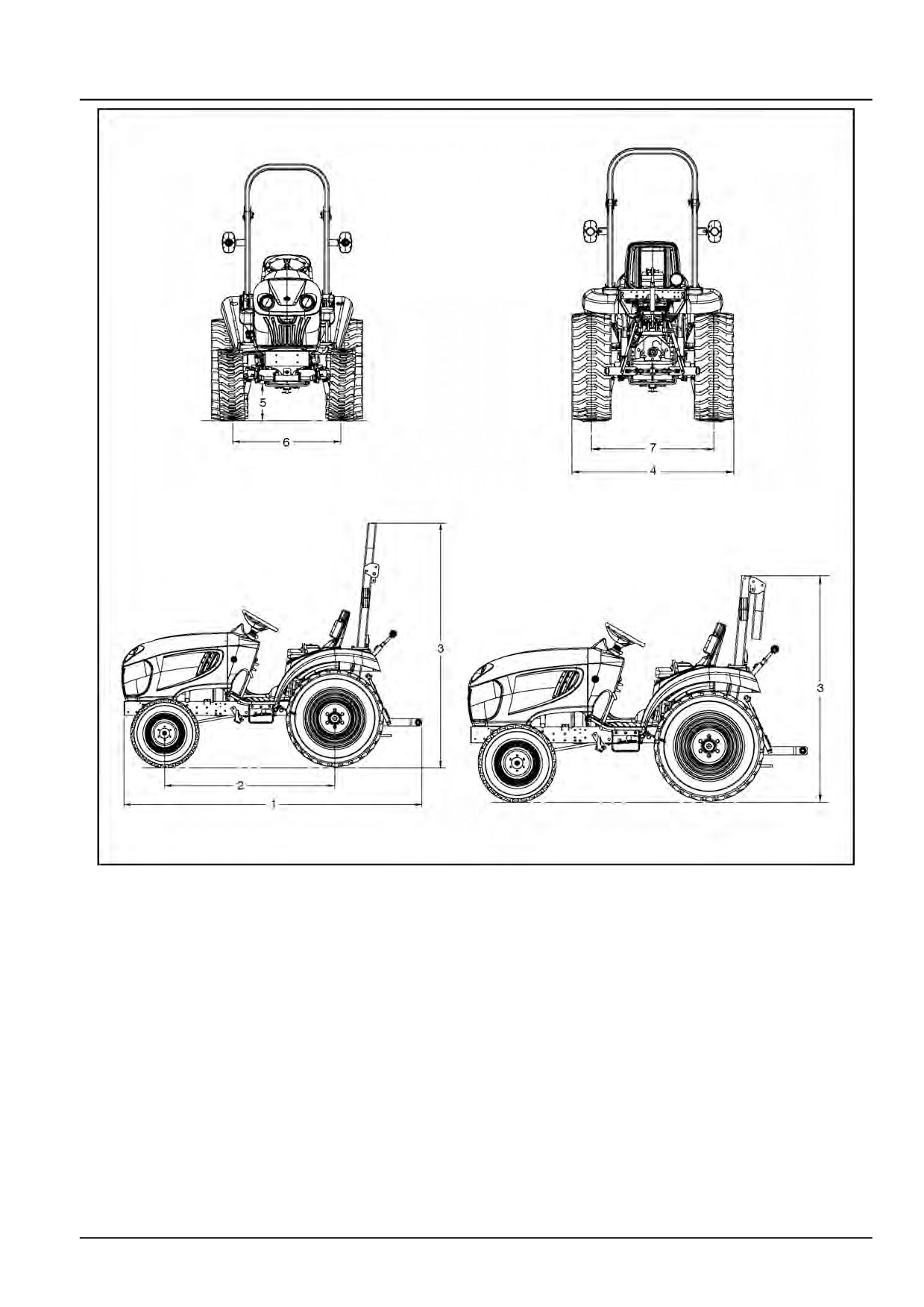
Dimension
Model Boomer
20
Model Boomer
25
(1) - LENGTH:
FWD:
2632 mm (103.6 in)
2632 mm (103.6 in)
(2) - WHEEL BASE:
FWD
2500 mm (98.4 in)
2500 mm (98.4 in)
(3) - Top of ROPS - Folding:
Ag Tires:
255/75-15.3
Up Position
2110 mm (83.1 in)
2110 mm (83.1 in)
Down Position
1705 mm (67.1 in)
1705 mm (67.1 in)
Ind. Tires:
12.00 x 16.5
Up Position
2127 mm (83.7 in)
2127 mm (83.7 in)
Down Position
1722 mm (67.8 in)
1722 mm (67.8 in)
Turf Tires:
33x 12.50-16.5
Up Position
2125 mm (83.6 in)
2125 mm (83.6 in)
Down Position
1720 mm (67.7 in)
1720 mm (67.7 in)
Flotation Tires:
380/55-17
Up Position
2147 mm (84.5 in)
2147 mm (84.5 in)
Down Position
1742 mm (68.6 in)
1742 mm (68.6 in)
Garden Pro:
280/70R16
Up Position
2110 mm (83 in)
2110 mm (83 in)
Down Position
1742 mm (68.6 in)
1742 mm (68.6 in)
AG Narrow 1:
9.5-16
Up Position
2123 mm (84 in)
2123 mm (84 in)
Down Position
1742 mm (68.6 in)
1742 mm (68.6 in)
AG Narrow 2:
9.5-16
Up Position
2123 mm (84 in)
2123 mm (84 in)
Down Position
1742 mm (68.6 in)
1742 mm (68.6 in)
(4) - WIDTH:
Rear Axle - Outside to Outside of tire:
Ag Tires:
1236 mm (48.7 in)
1236 mm (48.7 in)
255/75-15.3
Ind. Tires:
1276 mm (50.2 in)
1276 mm (50.2 in)
12.00 x 16.5
Turf Tires:
1276 mm (50.2 in)
1276 mm (50.2 in)
33x 12.50-16.5
Flotation Tires:
1392 mm (54.8 in)
1392 mm (54.8 in)
380/55-17
Garden Pro:
1180 mm (46 in)
1180 mm (46 in)
280/70R16
AG Narrow 1:
1146 mm (0.0 in)
1146 mm (0.0 in)
9.5-16
AG Narrow 2:
1226 mm (48 in)
1226 mm (48 in)
9.5-16
48017684 02/06/2016
27

INTRODUCTION
Model Boomer 20
Model Boomer 25
(5) - MINIMUM GROUND CLEARANCE (under drawbar support):
Ag Tires:
225 mm (8.86 in)
225 mm (8.86 in)
255/75-15.3
Ind. Tires:
242 mm (9.53 in)
242 mm (9.53 in)
12.00 x 16.5
Turf Tires:
240 mm (9.45 in)
240 mm (9.45 in)
33x 12.50-16.5
Flotation Tires:
262 mm (10.31 in)
262 mm (10.31 in)
380/55-17
Garden Pro:
220 mm (9 in)
220 mm (9 in)
280/70R16
AG Narrow 1:
238 mm (9 in)
238 mm (9 in)
9.5-16
AG Narrow 2:
238 mm (9 in)
238 mm (9 in)
9.5-16
48017684 02/06/2016
28
INTRODUCTION
76114213
1
48017684 02/06/2016
29

INTRODUCTION
Consumables
Lubricant
Type and Description
Part Number
Container Size
104104A1
0.946 l (1 US qt)
NEW HOLLAND AMBRA
139033A1
3.785 l (1 US gal)
SUPER GOLD 10W-30
104106A1
18.93 l (5 US gal)
Engine Oil
407410R2
0.946 l (1 US qt)
NEW HOLLAND AMBRA
139034A1
3.785 l (1 US gal)
SUPER GOLD 15W-40
407414R2
18.93 l (5 US gal)
NEW HOLLAND
AMBRA MULTI G
404787A1
18.93 l (5 US gal)
134™ HYDRAULIC
Transmission/Hydraulic Oil
TRANSMISSION OIL
NEW HOLLAND AMBRA
B17805
18.93 l (5 US gal)
F200A HYDRAULIC FLUID
NEW HOLLAND AMBRA
87299775
0.946 l (1 US qt)
Front Axle/Gear Oil
HYPOIDE 90
87299136
18.93 l (5 US gal)
NEW HOLLAND AMBRA
Grease
GR-9 MULTI-PURPOSE
132096A1
Tube 14 oz
GREASE
Ethylene Glycol Coolant
Coolant
Concentrate
48017684 02/06/2016
30

INTRODUCTION
Capacities
CAPACITIES
Fuel Tank
25.0 l (6.6 US gal)
25.0 l (6.6 US gal)
Cooling System
3.8 l (4.0 US qt)
3.8 l (4.0 US qt)
Engine Crankcase:
With Filter
4.2 l (4.4 US qt)
4.2 l (4.4 US qt)
Rear Axle & Transmission (Includes
24 l (6.3 US gal)
24 l (6.3 US gal)
Hydraulics)
Front Axle
3.0 l (3.2 US qt)
3.0 l (3.2 US qt)
48017684 02/06/2016
31
INTRODUCTION
Product identification
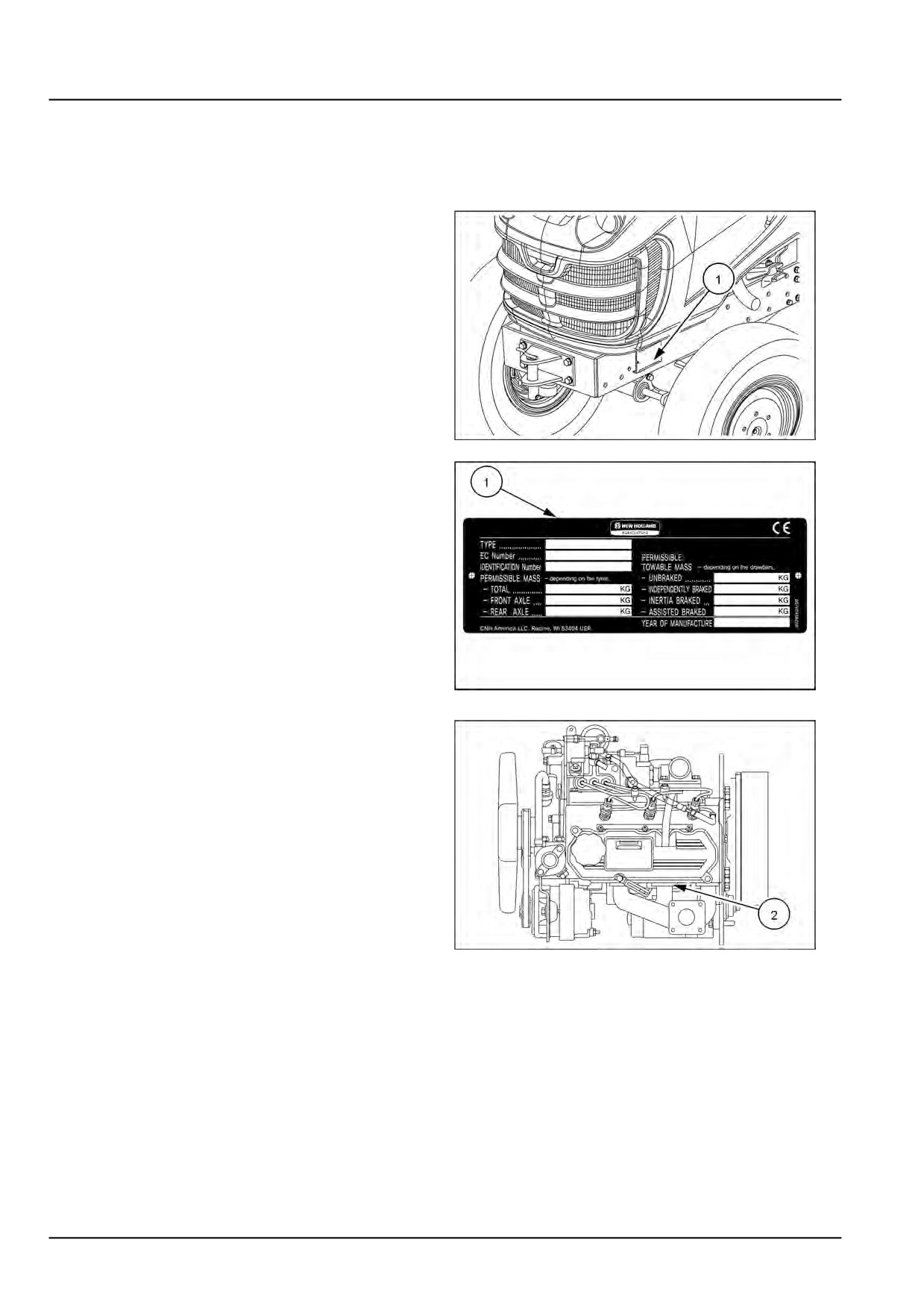
The machine and major components are identified with Product Identification Number (PIN) plates. You should supply
the PIN plate data to your NEW HOLLAND dealer when requesting parts or service, and also to identify the machine
in case of theft.
Product Identification Number (PIN) plate
The machine PIN Plate (1) is located on the left-hand side
of the frame.
NHIL16CT00203AA
1
NHIL13CT00853AA
2
Engine Product Identification Number (PIN)
plate
The engine PIN plate (2) is located on the rearward end
of the engine valve cover.
NHIL16CT00204AA
3
48017684 02/06/2016
32
INTRODUCTION
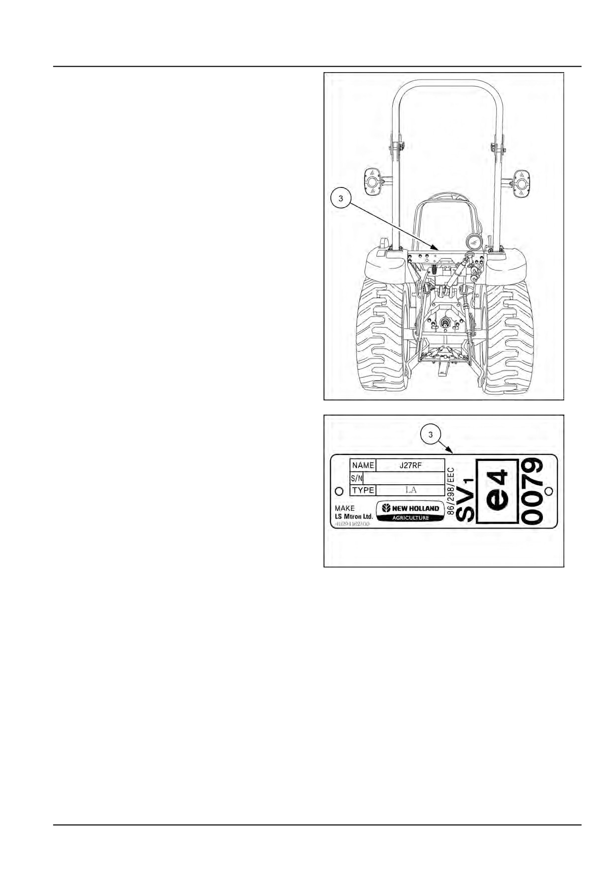
Roll Over Protective Structure (ROPS) Prod-
uct Identification Number (PIN)
The Roll Over Protective Structure (ROPS) PIN plate (3)
is located on the ROPS cross brace behind the fuel tank.
NHIL13CT00142BA
4
NHIL13CT00854AA
5
48017684 02/06/2016
33