New Holland 8.3 & 9.0L 6 Cylinder, 24 Valve CNH Engine with High Pressure Common Rail Fuel System. REPAIR MANUAL
NEW HOLLAND
REPAIR
MANUAL
8.3 & 9.0L 6 Cylinder, 24 Valve
CNH Engine with High Pressure
Common Rail Fuel System
SERVICE
87515684
2/06
CNH ENGINE
CNH ENGINE
REPAIR MANUAL
REPAIR MANUAL
8.3L, 9.0L, 6 Cyl, 24 Vlv.
8.3L, 9.0L, 6 Cyl, 24 Vlv.
High Pressure Common
High Pressure Common
Rail Fuel System
Rail Fuel System
87515682
87515682
CNH ENGINE
CNH ENGINE
REPAIR MANUAL
REPAIR MANUAL
8.3L, 9.0L, 6 Cyl, 24 Vlv.
8.3L, 9.0L, 6 Cyl, 24 Vlv.
High Pressure Common
High Pressure Common
Rail Fuel System
Rail Fuel System
87515682
87515682
87515683
Repair Manual Number 87515682
POWER PRODUCTION - B
87515684
Introduction
Engine - B.10.A
87515685
Fuel and Injection System - B.20.A
87515686
Air Intake System - B.30.A
Exhaust System - B.40.A
Engine Coolant System - B.50.A
Lubrication System - B.60.A
Starting System - B.80.A
You can order Repair Manual Books separately (see publication
numbers above) or you can order a complete Engine Repair Manual
(Publication Number 87515682).
390
REPAIR MANUAL
TG215 , TG245 , TG275 , TG305 , TJ280 , TJ330
87515682418/01/2006
Contents
INTRODUCTION
POWER PRODUCTION
B
ENGINE
B.10.A
FUEL AND INJECTION SYSTEM
B.20.A
AIR INTAKE SYSTEM
B.30.A
EXHAUST SYSTEM
B.40.A
ENGINE COOLANT SYSTEM
B.50.A
LUBRICATION SYSTEM
B.60.A
STARTING SYSTEM
B.80.A
87515682418/01/2006
Contents
INTRODUCTION
Foreword - How to use this manual ( - A.10.A.40)
3
Safety rules ( - A.50.A.10)
10
Basic instructions ( - A.90.A.05)
11
Torque ( - A.90.A.10)
14
Definition ( - A.92.A.15)
17
Conversion factors ( - A.92.A.21)
20
Product identification ( - A.80.A.10)
21
87515682 4 18/01/2006
2
Foreword - How to use this manual ( - A.10.A.40)
The information in this manual is organized using the Integrated Coding Environment (ICE). ICE is a shorthand
system for pointing to Sections, Chapters and sub-Chapters in the manual without using the words. ICE also
identifies the type of information at that location.
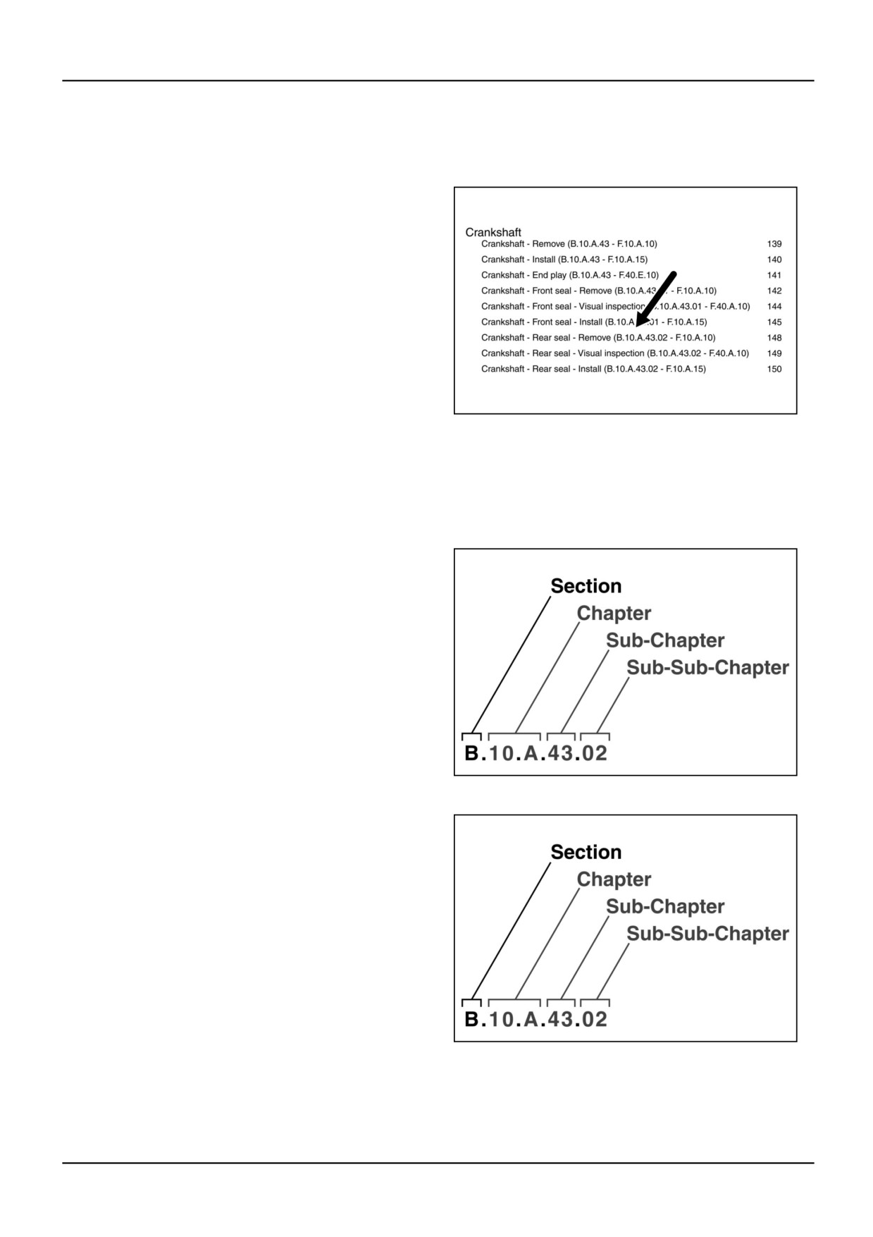
A search for information on an engine component will
likely begin at the Table of Contents (TOC) or the Index:
for example, a search for information on the rear seal
of the crankshaft. When you locate “crankshaft - rear
seal” in the TOC with the indicated page number, this
Foreword explains:
•
how to proceed to the correct location in the manual
based on the ICE code,
•
how to identify the type of information you may
expect at that location.
RCPH05CDC414ABA
1
NOTE: Due to differences in languages and models, the page number indicated in the illustration may not applicable
to your manual. Refer to the table of contents in your repair manual.
Location
The first half of an ICE code describes the location of
the information.
(The ICE code has two parts separated by a hyphen.
The first part describes the location. The periods break
up the ICE code into its parts.)
RCPH05CDC476ABA
2
The first letter identifies the section.
Sections are arranged alphabetically in a manual. This
engine repair manual is contained within one section -
the Power Production Section - signified by the letter
“B,” and all ICE references in the manual begin with the
letter “B.”
Do NOT confuse a section with a bound book. Because
of its size, a section may require more than one bound
book, sometimes a book for each chapter within a
section.
This repair manual, although contained within one
RCPH05CDC476ABA
3
section, requires more than one bound book. The book
cover always lists both the section(s) and chapter(s)
contained inside the bound book.
87515682 4 18/01/2006
3
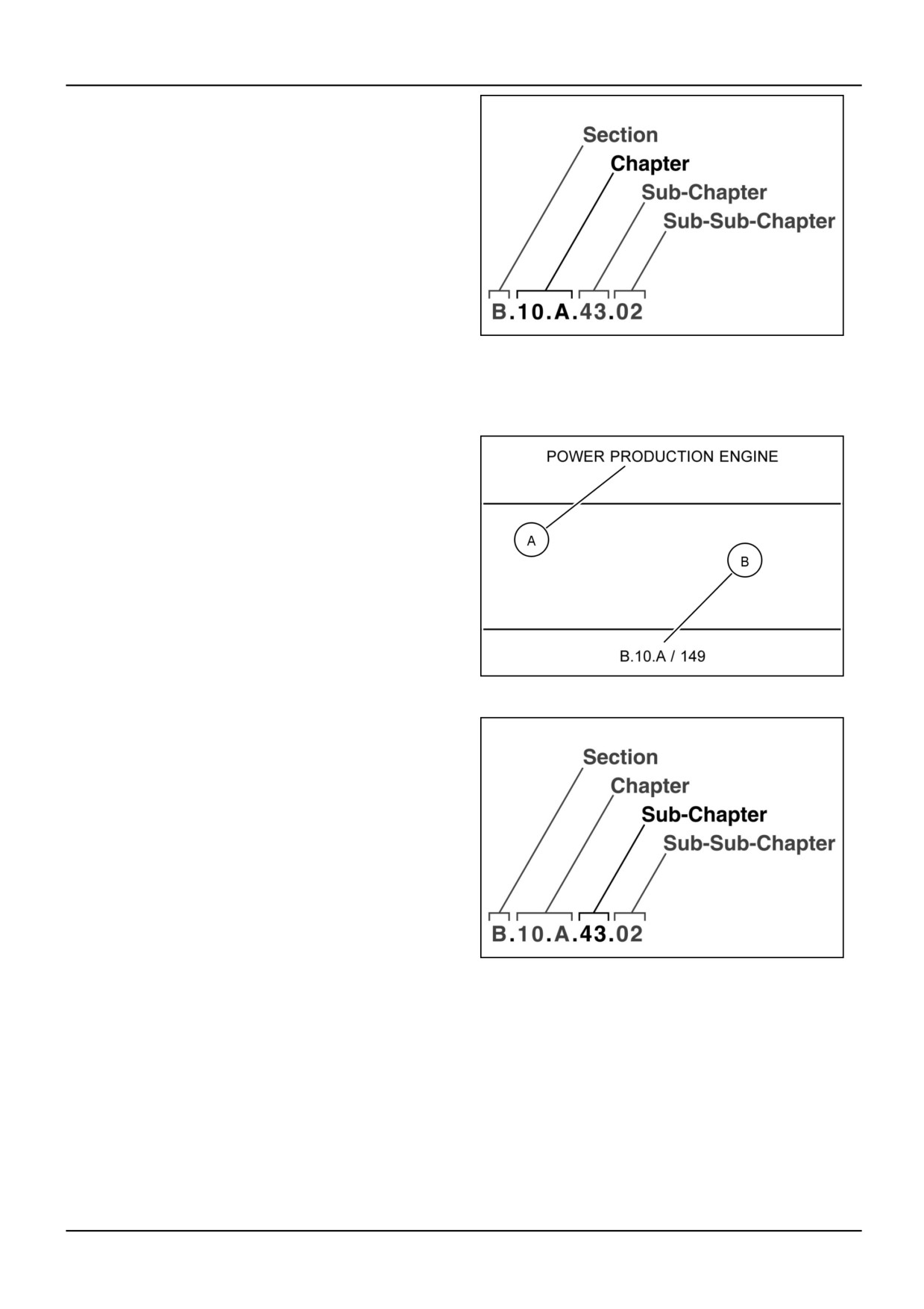
The second number and letter identify the chapter within
the section.
Chapters are arranged numerically within the section.
The chapters used in this manual are listed below:
ENGINE (B.10.A)
FUEL AND INJECTION SYSTEM (B.20.A)
AIR INTAKE SYSTEM (B.30.A)
EXHAUST SYSTEM (B.40.A)
ENGINE COOLANT SYSTEM (B.50.A)
LUBRICATION SYSTEM (B.60.A)
STARTING SYSTEM (B.70.A)
RCPH05CDC483ABA
4
The coding indicates that the rear seal is located in
Chapter 10.A (Engine), of Section B (Power Production).
The section and chapter titles (A) are displayed at the
top of each page in the body of the manual.
The ICE code for the section, chapter and page number
(for example, B.10.A/149) (B) are displayed at the bottom
of each page in the body of the manual.
RCPH05CDC407ABA
5
The last two positions in the location code always form
the title of the document - in this example, crankshaft -
rear seal.
The third number identifies a sub-chapter within the
chapter.
The number “43” represents the crankshaft and indicates
that rear seal information is located under crankshaft in
Chapter 10.A of Section B.
RCPH05CDC490ABA
6
87515682 4 18/01/2006
4
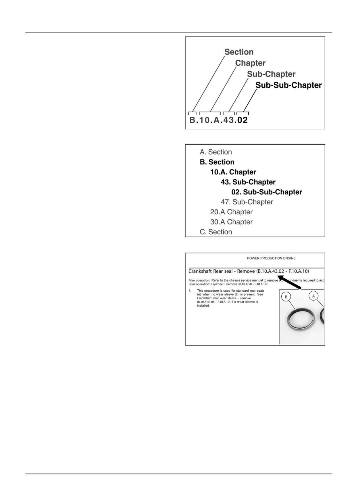
The fourth number identifies the rear seal itself, a
sub-topic (or sub-sub-chapter) of crankshaft. This is not
any rear seal; this is the rear seal for the crankshaft.
The page numbers for rear seal information within
Chapter 10.A are also given.
RCPH05CDC497ABA
7
If the same location is viewed as part of a manual outline,
the uniqueness of the location is apparent. Rear seal
information is the only information that will be found at
B.10.A.43.02 within the entire manual.
RCPH05CDC506ABA
8
When you locate the information at the given page
number, the page heading confirms the location.
RCPH05CDC393ABA
9
Information type (Infotype)
The information in each chapter, and therefore the table
of contents, is separated into four broad categories:
•
Technical Data
•
Functional Data
•
Service Data
•
Diagnostic Data
NOTE: The information in the Index for a chapter is organized alphabetically. The locations are listed alphabetically,
and then information from the different categories is listed alphabetically for the location.
87515682 4 18/01/2006
5
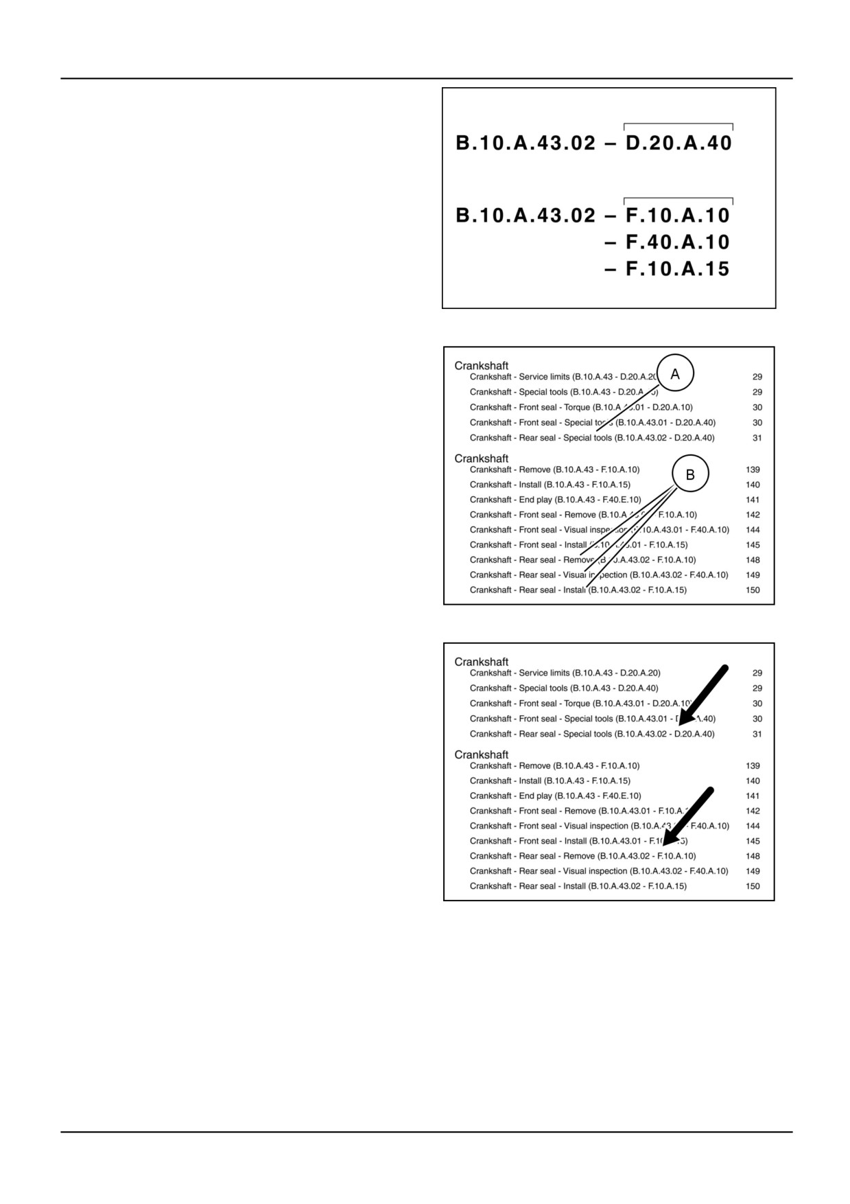
This is the order of the information in the chapter and the
table of contents. These are the exact headings used in
the table of contents to separate the information.
There may be information on any component, like the
rear seal of the crankshaft, in any of the four categories.
The location is the same - B.A.10.43.02 for all four
categories. The second part of the code which identifies
the type of information, or infotype, is different.
RCPH05CDC421ABA
10
In fact, there are only two types of information offered on
the crankshaft rear seal in this manual:
•
technical data which describes a special tool
needed for installation (A),
•
and service data, which describes seal removal,
inspection and installation (B).
The first grouping in the illustration is located under the
Technical Data heading in the TOC. The second grouping
is located under the Service Data heading in the TOC.
RCPH05CDC406ABA
11
The coding for technical information always begins with
the letter “D.” The coding for the service information
always begins with the letter “F.”
The first letter of the infotype code always explains the
category of the information:
D = technical data,
C = functional data,
F = service data,
G = diagnostic data.
RCPH05CDC406ABA
12
87515682 4 18/01/2006
6
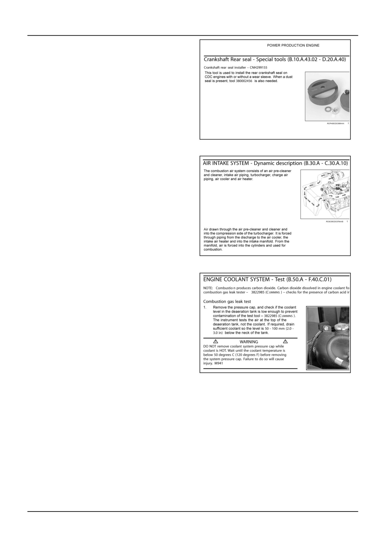
Technical data may be:
•
a specification for the engine, the fuel system, the
air intake system, etc.,
•
a special tool, whether recommended or required,
to perform a service procedure on the component,
•
a torque value for installing a component,
•
a service limit criterion, for determining when
a component must be replaced or the pass/fail
criterion for a test.
RCPH05CDC422ABA
13
Functional data may be:
•
a dynamic description of how a system or
sub-system works during operation,
•
a static description of a system component,
•
an identification illustration to show the location
of components - sensor locations, fuel system
components, lubrication system components, etc.
RCPH05CDC429ABA
14
Service data may be:
•
a basic service action like remove, disassemble,
assemble or install,
•
an inspection or testing procedure,
•
an adjusting or measuring procedure.
RCPH05CDC436ABA
15
87515682 4 18/01/2006
7
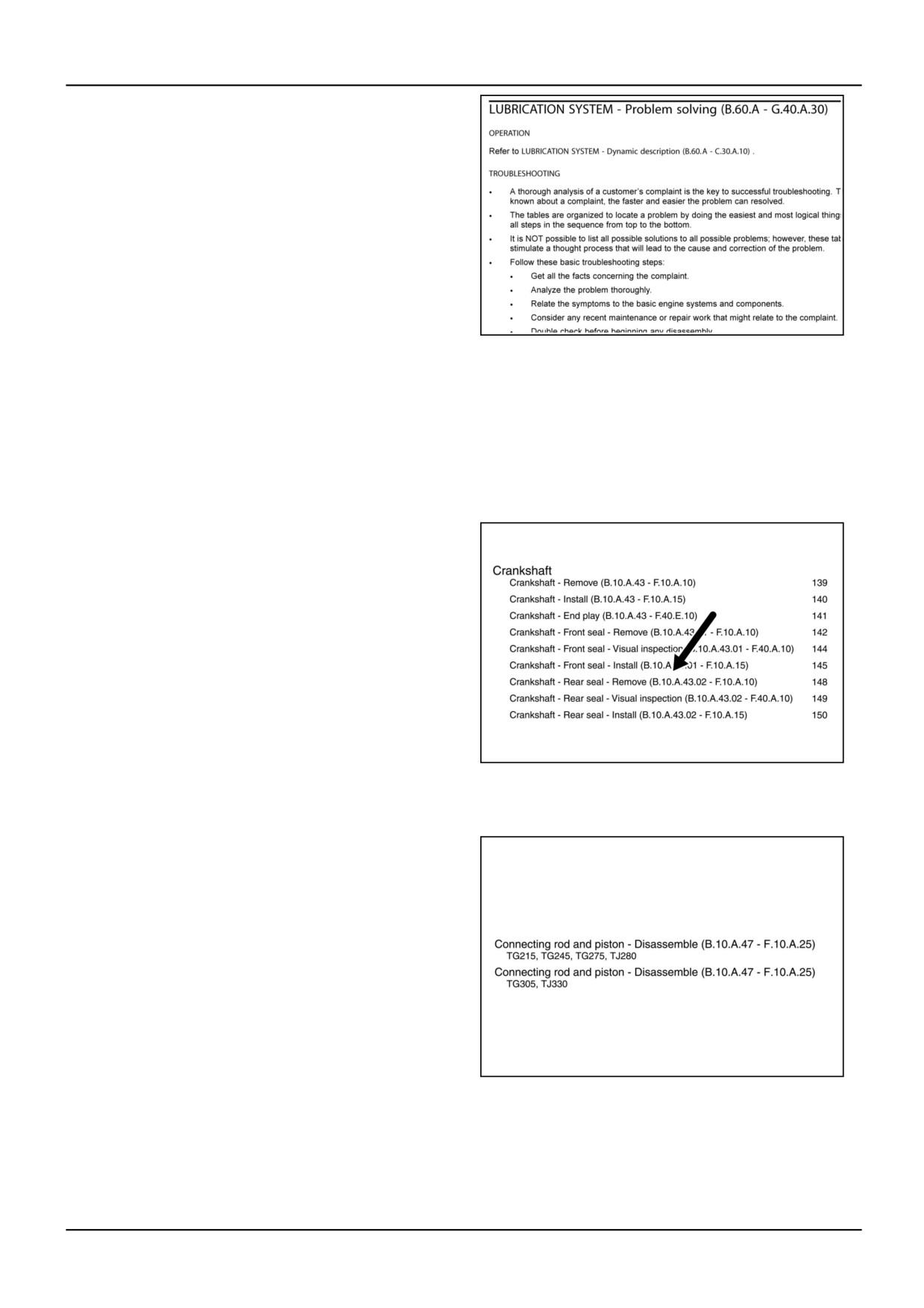
Diagnostic data may be:
•
guided troubleshooting to correct a problem,
•
symptom-based troubleshooting to locate the
source of a problem.
RCPH05CDC443ABA
16
When searching for information in the table of contents
or the index, pay attention to the first letter of the infotype
and its title (special tool, dynamic description, remove,
problem-solving) so you find the type of information you
are seeking.
Applicability - Does the information apply to my model?
If an entry in the table of contents or the index has no
models listed immediately beneath it, the information
applies to all models listed on the repair manual, section
or chapter cover.
The information shown is applicable to all models.
RCPH05CDC414ABA
17
When an entry in the TOC or index has models listed
below it, the information applies only to those models.
Although the location code, infotype code and title of the
entry are exactly the same, the model names inform you
that the content varies by model.
Go to the page number listed for your model. When you
locate the information in the manual, the same models
are listed below the title to confirm that you are at the
right location.
RCPH05CDC503ABA
18
87515682 4 18/01/2006
8
Prior Operation and Next Operation
This manual makes extensive use of “Prior operation”
and “Next operation” lists to avoid repetition.
A “Prior operation” list always occurs at the beginning of
document and points to procedures which must precede
the current procedure.
A “Next operation” list always occurs at the end of a
document and points to procedures which must follow
the current procedure in order to restore the engine to
active service.
RCPH05CDC466ABA
19
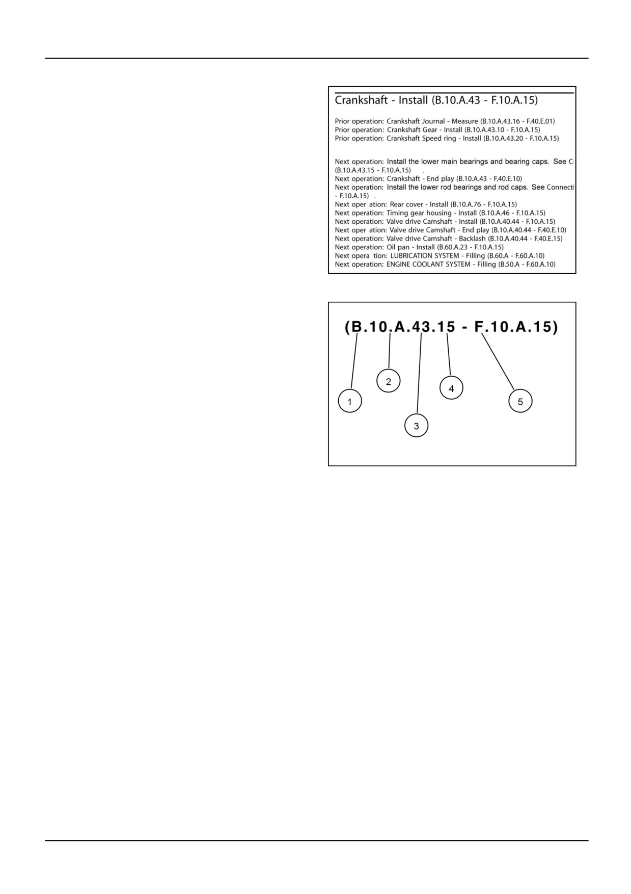
Prior and Next operations usually contain an ICE code
reference which follows the same format as previously
explained. For example, installation of the lower main
bearings and bearing caps is the first operation listed
after the crankshaft is installed. The ICE code given is
(B.10.A.43.15 - F.10.A.15) with the title, Crankshaft Main
Bearing - Install.
The location code points to the sub-topic main bearings
(4), in the sub-chapter on the crankshaft (3), in Chapter
10.A (2), of Section B (1).
The infotype code points to a service procedure because
of the initial letter “F” that is located under Service Data
RCPH05CDC473ABA
20
in the table of contents.
87515682 4 18/01/2006
9
com/
Safety rules ( - A.50.A.10)
Read and understand all of the safety precautions and warnings before performing any repair. This list contains
the general safety precautions that must be followed for your personal safety. Additional safety precautions are
included in the procedures where they apply.
General safety precautions
•
The work area around the engine must be dry, well lit, ventilated, free from clutter, ignition sources and
hazardous substances.
•
Always wear protective glasses and protective shoes when working.
•
Stay clear of rotating parts which can cut, mutilate or strangle.
•
Do NOT wear loose-fitting or torn clothing. Remove all jewelry when working.
•
Disconnect the battery [negative (-) cable first] and discharge any capacitors before beginning any repair work.
Put a “Do NOT Operate” tag in the cab or on the controls.
•
Only use proper engine barring techniques when rotating the engine manually. Do NOT attempt to rotate the
crankshaft by pulling or prying on the fan. This practice may cause serious personal injury, property damage,
fan damage or premature fan failure.
•
When coolant is hot from engine operation, allow the engine to cool before slowly loosening the pressure cap
to relieve pressure in the cooling system.
•
ALWAYS use blocks or the proper engine stand to support the engine before performing any repair work. Do
NOT work on an engine which is only supported by floor jacks or a hoist.
•
Relieve all pressure in the air, oil and cooling systems before any lines, fittings or related items are removed or
disconnected. Be alert for possible pressure when disconnecting any component from a system that uses
pressure. Do NOT check for leaks with your hand. High pressure oil or fuel can cause personal injury.
•
To reduce the possibility of personal injury, use a hoist or an assistant when lifting components that weigh 23
kg (50 lb) or more. Make sure all lifting equipment - such as chains, hooks or slings - is in good condition and
of the correct capacity. Make sure all lift hooks are positioned correctly. ALWAYS use a spreader bar when
necessary; lifting hooks must NOT be side-loaded.
•
Corrosion inhibitor, a component of coolant additives and lubricating oil, contains alkali. Do NOT get the
substance in eyes. Avoid prolonged or repeated contact with skin. Do NOT swallow internally. In case of
contact, immediately wash skin with soap and water. In case of contact, immediately flood eyes with large
amounts of water for a minimum of 15 minutes. IMMEDIATELY CALL A PHYSICIAN. KEEP OUT OF THE
REACH OF CHILDREN.
•
Naptha and Methy Ethyl Ketone (MEK) are flammable materials and MUST be used with caution. Follow the
manufacturer’s instructions when using these materials. KEEP OUT OF THE REACH OF CHILDREN.
•
To prevent burns, be aware of heated parts and hot fuel in lines, tubes and compartments on recently
operated engines.
•
ALWAYS use tools that are in good condition. Understand the correct use of the tool before performing repair
work. Use ONLY genuine CNH replacement parts.
•
ALWAYS use the same fastener part number (or equivalent) when replacing fasteners. Do NOT use a fastener
of lesser quality when replacing components.
•
Do not perform any repair when fatigued or after consuming alcohol or drugs that can impair your functioning.
•
Some government agencies have determined that used engine oil can be carcinogenic and can cause
reproductive toxicity. Avoid inhalation of vapors, ingestion and prolonged contact with used engine oil.
•
Coolant is toxic. If NOT reused, follow local environmental regulations for proper disposal.
87515682 4 18/01/2006
10
Basic instructions ( - A.90.A.05)
Definition of “clean”
Parts must be free of debris that can contaminate any engine system. This does not mean that cleaned parts
have to appear to be new.
Abrasive pads and abrasive paper
There is no part of an engine designed to withstand abrasion. All engine components are designed to lock together
or slide across each other. Abrasives and dirt particles will degrade both functions.
CNH does NOT recommend the use of emery cloth or sand paper on any part of an ASSEMBLED engine or
component, especially for removing the carbon ridge from cylinder liners or to clean block decks or counterbores.
Use abrasive products with great care when cleaning engine parts, particularly on partially assembled engines.
These cleaning products come in many forms and sizes. All contain aluminum oxide particles, silicon carbide, sand
or some other similar hard material. These materials are harder than most parts of the engine. When pressed
against a softer material, they will either damage the material or become embedded in it.
Once embedded in a part, the abrasive particle will abrade the other part it contacts until contact is no longer
made between the two parts. If the damage sufficiently degrades the oil film, the two parts may fail prematurely
from ineffective lubrication.
In addition, particles fall off of the holding material as the abrasive product is being used.
Gasket surface
The object in cleaning gasket surfaces is to remove gasket material, not to refinish the gasket surface on the part.
CNH does NOT recommend any specific brand of liquid gasket remover. If a liquid gasket remover is used, check
the manufacturer’s directions to make sure the part being cleaned will not be damaged.
Air powered gasket scrapers can save time, but the surface cannot be damaged in the process.
All old gasket material must be removed from the gasket mating surfaces. However, it is not necessary to clean
and polish the gasket surface until the machining marks are erased. Excessive sanding or buffing can damage the
gasket sealing surface. Surface finish and flatness tolerances must be maintained to form a quality sealing surface.
Solvents and acid cleaning
Solvents and acid-type cleaner can be used to clean disassembled engine parts (with the exception of pistons). The
best results are obtained with a cleaner that can be heated to 90 - 95 °C (180 - 200 °F). CNH does NOT recommend
any specific brand of cleaner. Always follow the manufacturer’s instructions when using cleaning solutions.
WARNING
When using solvents, acids or alkaline materials for cleaning, follow the manufacturer’s recommendations
for use. Wear goggles and protective clothing to reduce the possibility of personal injury. M995
Kerosene emulsion based cleaners work the best for cleaning pistons. These cleaners should NOT be heated to
temperatures in excess of 82 °C (180 °F). The cleaners begin to break down at temperatures in excess of 82 °C
(180 °F) and will be less effective.
Do NOT use solutions composed primarily of chlorinated hydrocarbons with cresols, phenols and/or cresylic
components. These solutions often do NOT clean well and are costly to dispose of properly.
Solutions with a pH above 7.0 are considered alkaline and those below 7.0 are acidic. The solutions become highly
alkaline or highly acidic the further they move from the neutral 7.0. Solutions with a pH above approximately 9.5
cause aluminum to turn black; highly alkaline solutions must NOT be used.
A cleaning tank that provides a constant mixing and filtering of the cleaning solution will yield the best results.
87515682 4 18/01/2006
11
•
Remove all gasket material, O-rings and sludge or carbon deposits with a wire brush or scraper before putting
the parts in the cleaning tank.
•
When possible, use high pressure water or steam clean the parts before submerging them in the tank.
Removing the heaviest dirt before tank cleaning will allow the cleaner to work more effectively.
•
Rinse all parts in hot water after cleaning. Dry completely with clean shop air. Use air to remove the rinse
water from all cap screw holes and the oil drillings.
•
If the parts are NOT to be used immediately after cleaning, dip them in a suitable rust proofing compound.
This compound MUST be removed from the parts before assembly or installation on the engine.
Steam cleaning
Steam cleaning can be used to remove all types of dirt that may contaminate the cleaning tank. Steam cleaning is
an excellent method for cleaning oil drillings and coolant passages.
WARNING
Always wear protective clothing, safety glasses or a face shield when using a steam cleaner or power
washer. Failure to wear protective equipment can cause serious injury. M927
The following components should NEVER be steam cleaned:
- electrical components
- belts and hoses
- wiring harnesses
- bearings (ball or tapper roller)
– injectors
- electronic control module (ECM)
– fuel pump
- ECM connectors
Plastic bead cleaning
CNH recommends using ONLY plastic bead media on any engine part.
CNH does NOT recommend the use of glass bead blast or walnut shell media on ANY engine part. NEVER use
sand as a blast media on any engine part. Glass and walnut shell media can cause excess dust and can embed in
engine parts, which can result in premature component failure from abrasive wear.
Plastic beading can be used on many engine components to remove carbon deposits. The cleaning process is
controlled by the use of plastic beads, the operating pressure and the cleaning time.
CAUTION
Do not use the bead blasting cleaning method on aluminum piston skirts or bore pins in any piston, piston
skirt or piston crown. Small particles of the media will embed in the aluminum or other soft metal and result
in premature wear of the cylinder liner, piston rings, pins and pin bores. Valves, turbocharger shafts, etc.
can also be damaged. Follow the cleaning methods specified in the procedure. M1064
CAUTION
Do not contaminate wash tanks and tank type solvent cleaners with foreign material and plastic beads.
Remove the foreign material and plastic beads with compressed air, hot high pressure water or steam before
placing them in tanks and cleaners. The foreign material and plastic beads can contaminate the tank and any
other engine parts cleaned in the tank. Contaminated parts may cause failures from abrasive wear. M1065
Plastic bead material (U.S. size 16-20) can be used to clean piston ring grooves. Do NOT use bead blasting
media on piston pin bores or aluminum skirts. Bead blasting is best used on stubborn dirt or carbon build-up that
has NOT been removed by steam or high pressure washing, followed by cleaning in a heated wash tank. This
is particularly true of pistons: steam and soak the pistons first and then use the plastic bead method to safely
remove the carbon remaining in the grooves.
Follow the equipment manufacturer’s cleaning instructions. Adjust the air pressure in the blasting machine to
the manufacturer’s recommendation. Use these guidelines when plastic bead blasting recommendations are
not available:
87515682 4 18/01/2006
12
•
Use plastic bead size 16-20 (U.S. size) or equivalent.
•
Use an operating pressure of 270 kPa (40 psi) for piston cleaning. Pressure should not cause the beads to
break.
•
Steam clean or wash the parts with solvent to remove all foreign material and plastic beads after cleaning.
Rinse with hot water. Dry with compressed air.
CAUTION
Bead blasting must not disturb the metal surface of the component. If the metal surface is disturbed,
the engine can be damaged due to increased parts clearance or inadequate surface finish on parts that
move against other parts. M1066
•
When cleaning pistons, it is NOT necessary to remove all the dark stain from the piston. Removing the carbon
on the rim and from the ring grooves IS necessary. Direct the blast across the part rather than straight at the
part. If machining marks are disturbed by the blasting process, the pressure is too high or the blast is being
held on one spot too long. The blast operation must not disturb the metal surface.
•
Always direct the bead blast nozzle across rather than at the part. This allows the beading to get under the
unwanted material. Keep the nozzle moving, rather than held in one spot, to prevent surface damage.
•
Never bead blast valve stems. Tape or use a sleeve to protect the stems during bead blasting. Direct the
nozzle across the seat surface and radius rather then straight at them.
87515682 4 18/01/2006
13
Torque ( - A.90.A.10)
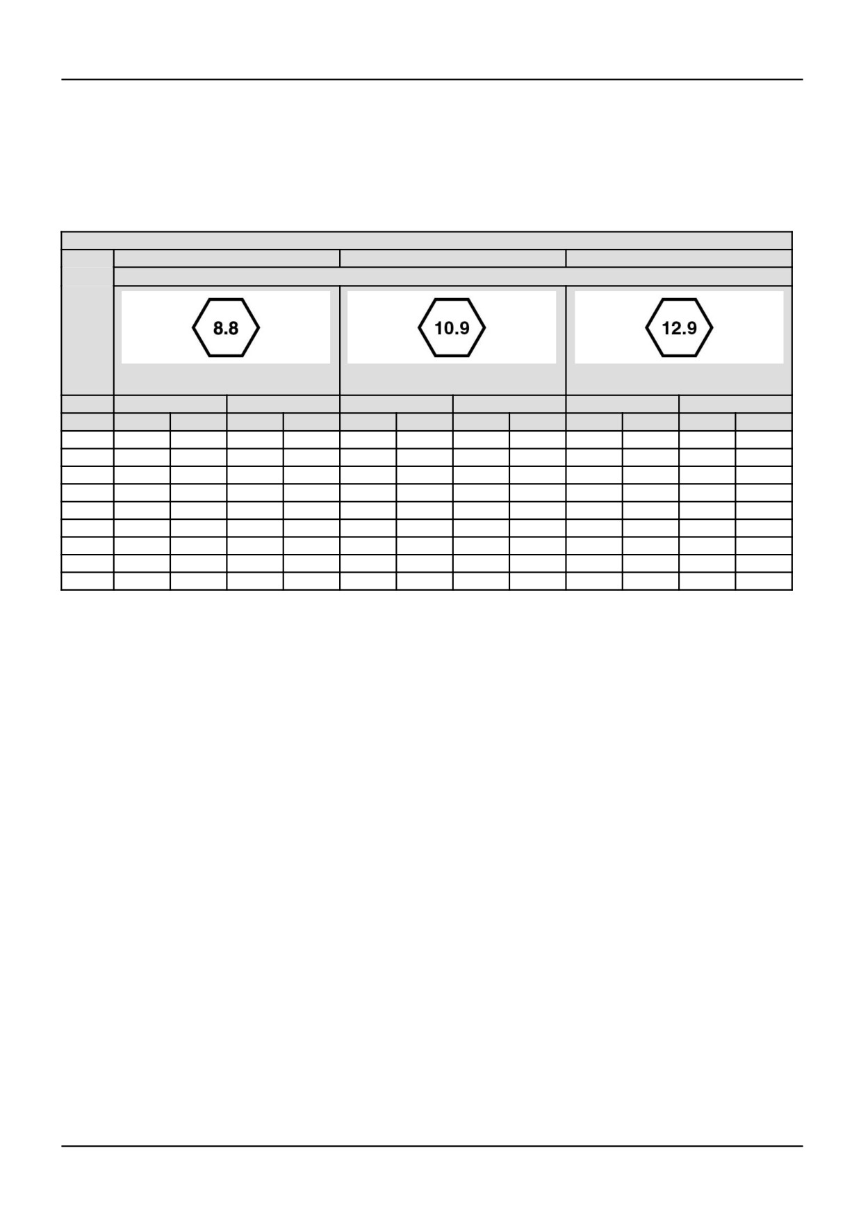
IMPORTANT: When replacing cap screws, always use a cap screw of the same measurement and strength as
the cap screw being replaced.
Metric cap screws and nuts are identified by the grade number stamped on the head of the cap screw or on the
surface of the nuts. U.S. customary cap screws are identified by radial lines stamped on the head of the cap screw.
Cap screw marking and torque value - Metric
Commercial steel class
8.8
10.9
12.9
Cap screw head marking
rh04h178
1
rh04h179
2
rh04h180
3
Dia.
Cast iron
Aluminum
Cast iron
Aluminum
Cast iron
Aluminum
mm
Nm
ft lb
Nm
ft lb
Nm
ft lb
Nm
ft lb
Nm
ft lb
Nm
ft lb
6
9
5
7
4
13
10
7
4
14
9
7
4
7
14
9
11
7
18
14
11
7
23
18
11
7
8
23
17
18
14
33
25
18
14
40
29
18
14
10
45
33
30
25
65
50
30
25
70
50
30
25
12
80
60
55
40
115
85
55
40
125
95
55
40
14
125
90
90
65
180
133
90
65
195
145
90
65
16
195
140
140
100
280
200
140
100
290
210
140
100
18
280
200
180
135
390
285
180
135
400
290
180
135
20
400
290
-
-
550
400
-
-
-
-
-
-
NOTES
1.
Always use the torque values listed in the above table when specific torque values are not supplied in a
procedure.
2.
Do NOT use these torque values in place of specified torque values in a procedure.
3.
The values in the table are based on lubricated threads.
87515682 4 18/01/2006
14
com/
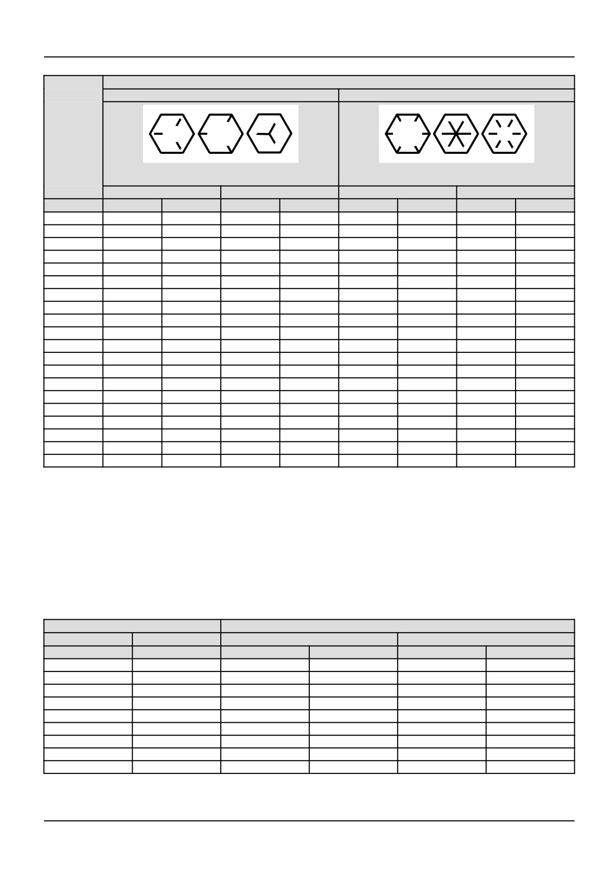
Cap screw marking and torque value - U.S. Customary
Cap screw head marking
SAE Grade 5
SAE Grade 8
rh04h175
4
rh04h176
5
Cast iron
Aluminum
Cast iron
Aluminum
Body size
Nm
ft lb
Nm
ft lb
Nm
ft lb
Nm
ft lb
1/4 - 20
9
7
8
6
15
11
8
6
1/4 - 28
12
9
9
7
18
13
9
7
5/16 - 18
20
15
16
12
30
22
16
12
5/16 - 24
23
17
19
14
33
24
19
14
3/8 - 16
40
30
25
20
55
40
25
20
3/8 - 24
40
30
35
25
60
45
35
25
7/16 - 14
60
45
45
35
90
65
45
35
7/16 - 20
65
50
55
40
95
70
55
40
1/2 - 13
95
70
75
55
130
95
75
55
1/2 - 20
100
75
80
60
150
110
80
60
9/16 - 12
135
100
110
80
190
140
110
80
9/16 - 18
150
110
115
85
210
155
115
85
5/8 - 11
180
135
150
110
255
190
150
110
5/8 - 18
210
155
160
120
290
215
160
120
3/4 - 10
325
240
255
190
460
340
255
190
3/4 - 16
365
270
285
210
515
380
285
210
7/8 - 9
490
360
380
280
745
550
380
280
7/8 - 14
530
390
420
310
825
610
420
310
1-8
720
530
570
420
1100
820
570
420
1 - 14
800
590
650
480
1200
890
650
480
NOTES
1.
Always use the torque values listed in the above table when specific torque values are not supplied in a
procedure.
2.
Do NOT use these torque values in place of specified torque values in a procedure.
3.
The values in the table are based on lubricated threads.
4.
When a ft-lb value is less than 10, convert the ft-lb value to in-lb to obtain a better torque with an in-lb wrench.
Pipe plug torque values
Size
Torque
Thread
Actual thread OD
In aluminum housing
In cast iron or steel housing
in
in
Nm
ft-lb
Nm
ft-lb
1/16
0.32
5
45 lb in
15
10
1/8
0.41
15
10
20
15
1/4
0.54
20
15
25
20
3/8
0.68
25
20
35
25
1/2
0.85
35
25
55
40
3/4
1.05
45
35
75
55
1
1.32
60
45
95
75
1-1/4
1.66
75
55
115
85
1-1/2
1.90
85
65
135
100
87515682 4 18/01/2006
15
com/
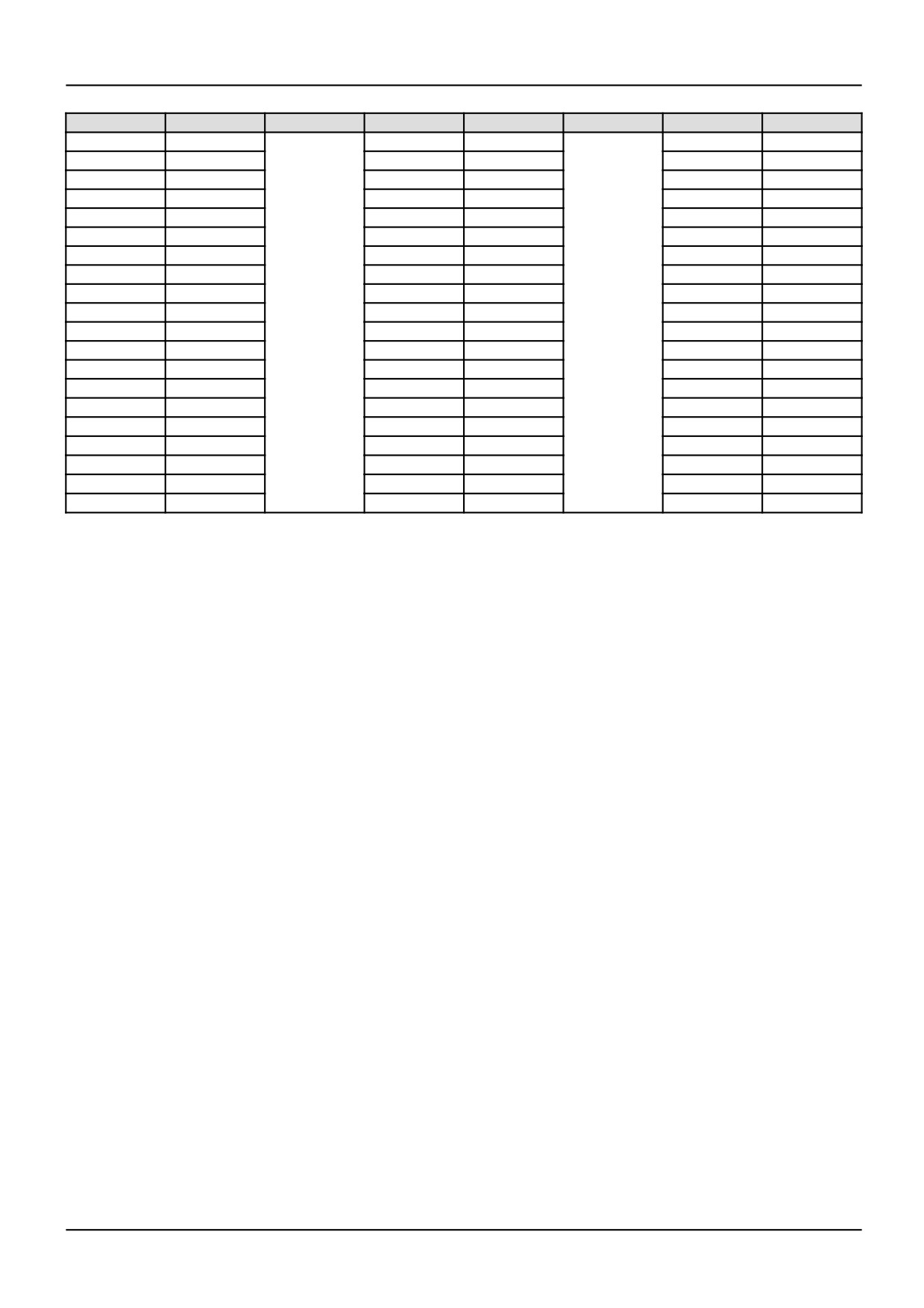
Newton-meter to pound-foot conversion
N•m
lb-in/lb-ft
N•m
lb-ft
N•m
lb-ft
1
9 lb in
55
41
155
114
5
44 lb in
60
44
160
118
6
53 lb in
65
48
165
122
7
62 lb in
70
52
170
125
8
71 lb in
75
55
175
129
9
80 lb in
80
59
180
133
10
89 lb in
85
63
185
136
11
97 lb in
90
66
190
140
12
106 lb in
95
70
195
144
14
124 lb in
100
74
200
148
15
133 lb in
105
77
205
151
16
142 lb in
110
81
210
155
18
159 lb in
115
85
215
159
20
15 lb ft
120
89
220
162
25
18 lb ft
125
92
225
165
30
22 lb ft
130
96
230
170
35
26 lb ft
135
100
235
173
40
30 lb ft
140
103
240
177
45
33 lb ft
145
107
245
180
50
37 lb ft
150
111
250
184
87515682 4 18/01/2006
16
Definition ( - A.92.A.15)
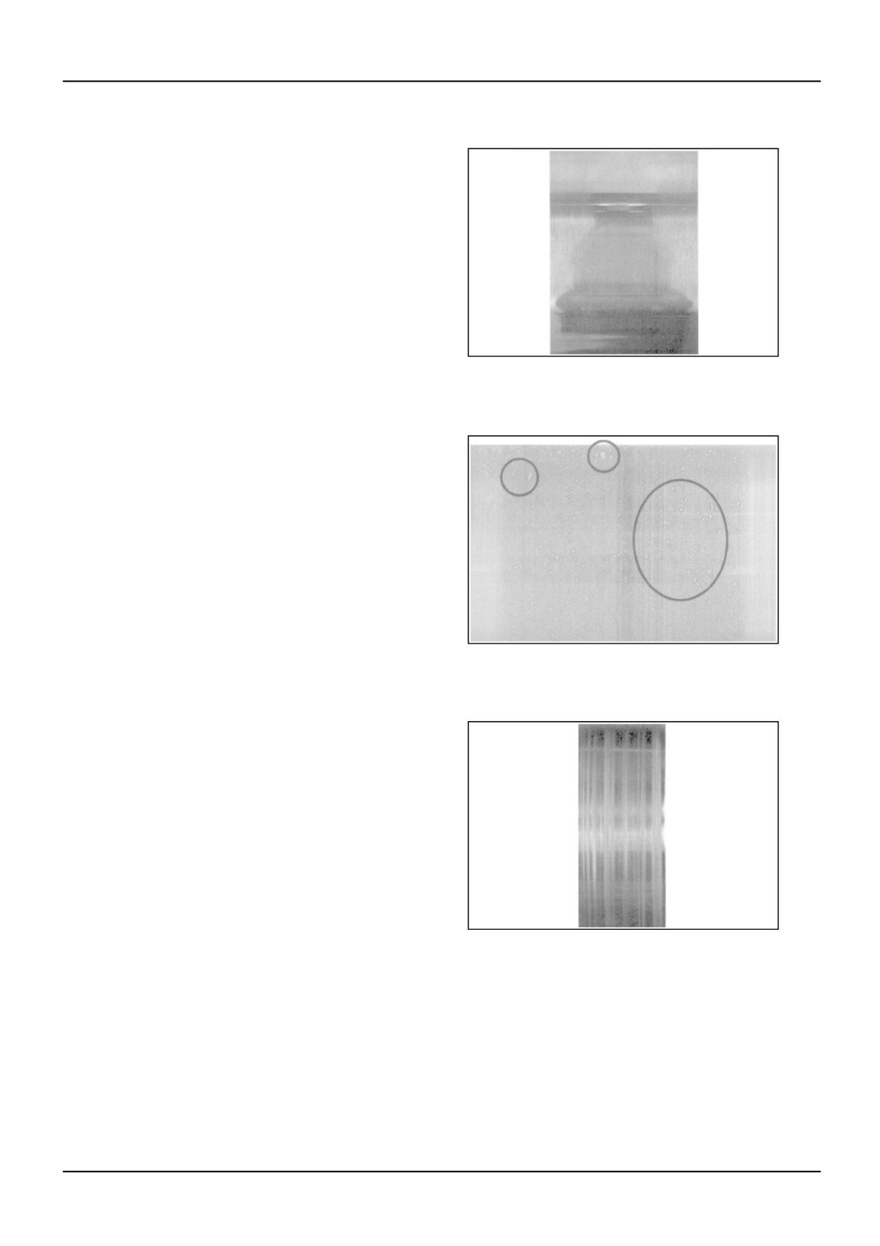
Polishing
Polishing is a normal surface condition where machining
lines have been smoothed from contact between mating
parts.
RCPH05CDC003AAA
1
Denting
A dent is a depression left in the surface by a piece of
foreign material that is trapped between two parts. A
dent has a relatively smooth, shiny bottom and does
NOT have rough or sharp edges.
RCPH05CDC004AAA
2
Frosted bands
Frosted bands are created by high density micro-denting.
The bands are “frosted” or white in appearance. Frosted
bands are not detectable with a fingernail.
RCPH05CDC005AAA
3
87515682 4 18/01/2006
17
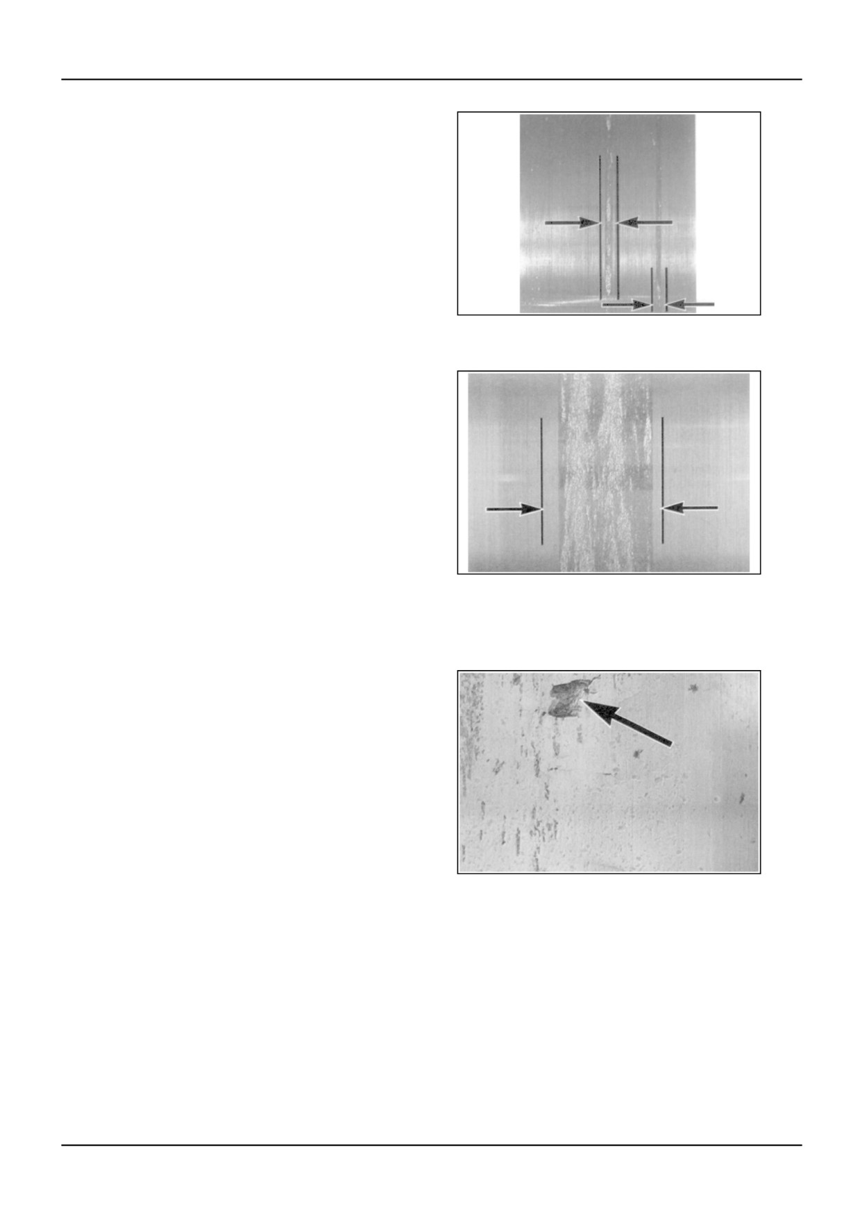
Galling
Galling is the transfer of material from one part to the
surface of another mating part. Galling typically occurs
when one part skids, rather than glides, on the surface
of another part - e.g., a roller tappet on the camshaft
lobe. The extent of the galling determines whether the
part must be replaced.
RCPH05CDC006AAA
4
Surface distress: conditional reuse
RCPH05CDC007AAA
5
Major surface distress: no reuse
Pitting
Pitting is the loss of material from a part resulting in a
hole that is visible to the naked eye. Pits typically have
rough dark bottoms and sharp edges, and usually occur
in heavily-loaded areas on the part.
RCPH05CDC008AAA
6
87515682 4 18/01/2006
18
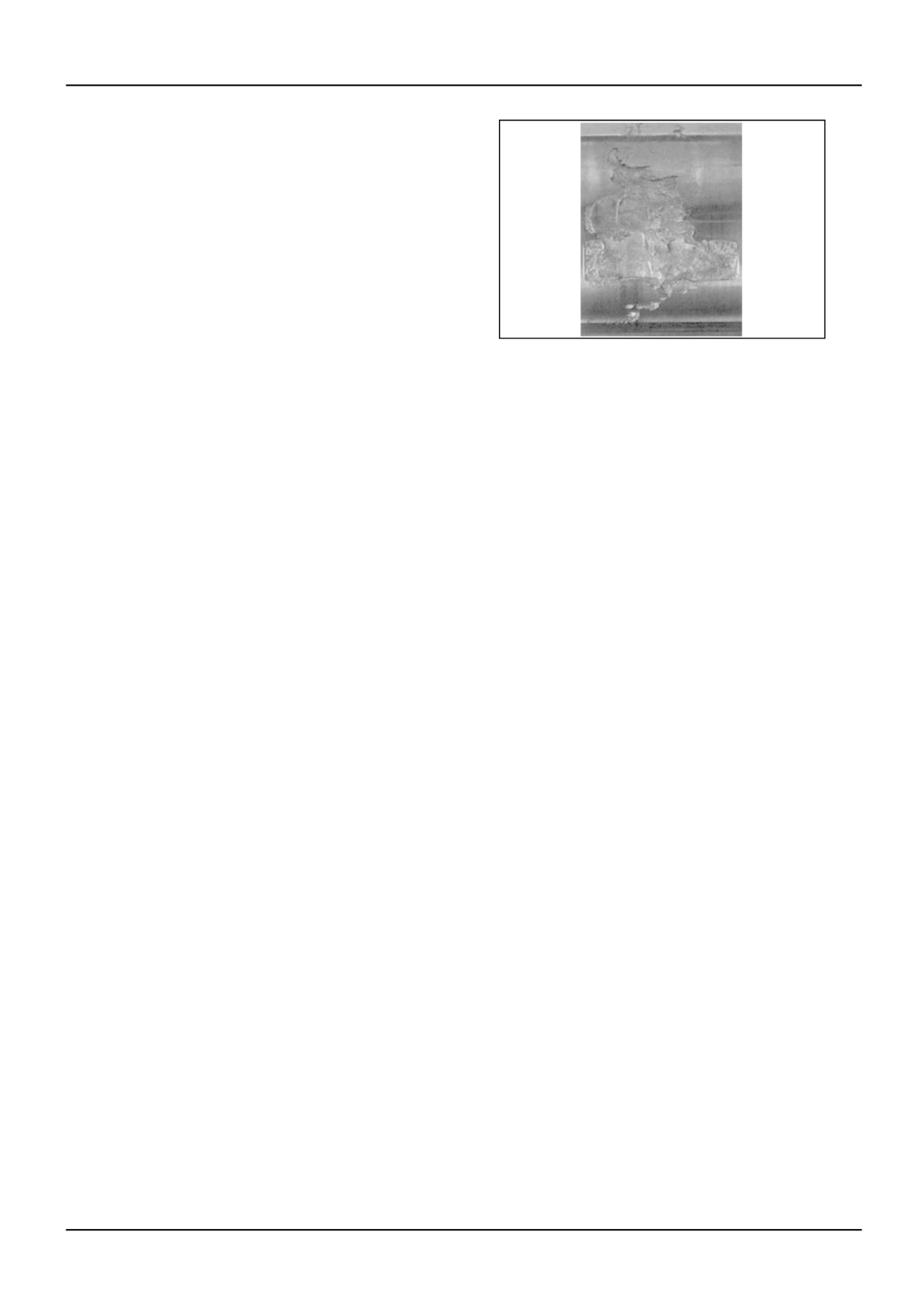
Macro-Spalling
Macro-spalling is the loss of large material from the
surface of a part. This amount of damage will affect the
operation of the engine.
RCPH05CDC009AAA
7
87515682 4 18/01/2006
19
com/
Conversion factors ( - A.92.A.21)
Weights and measures
Category
Metric
U.S. Customary
Metric to U.S.
U.S.
Unit name
Abbreviation
Unit name
Abbreviation
Customary -
Customary
Multiply by
to Metric -
Multiply by
Area
sq. millimeter
mm²
sq. inch
in²
0.001550
645.16
sq. centimeter
cm²
0.155
6.452
sq. meter
m²
sq. foot
ft²
10.764
0.0929
Fuel
gram per
g/kW-hr
pound per
lb/hp-hr
0.001645
608.277
consumption
kilowatt hour
horsepower
hour
Fuel
kilometer per
km/l
mile per gallon
mpg
2.352
0.4251
performance
liter
liter per
l/km
gallon per mile
gpm
0.4251
2.352
kilometer
Force
Newton
N
pound force
lbf
0.224809
4.4482
Length
millimeter
mm
inch
in
0.039370
25.40
millimeter
mm
foot
ft
0.00328
304.801
Power
kilowatt
kW
horsepower
hp
1.341
0.746
Pressure
kilopascal
kPa
pound force
psi
0.145037
6.8948
per sq. inch
kilopascal
kPa
inch of mercury
in Hg
0.29613
3.3769
kilopascal
kPa
inch of water
in H2O
4.019299
0.2488
millimeter of
mm Hg
inch of mercury
in Hg
0.039370
25.40
mercury
millimeter of
mm H2O
inch of water
in H2O
0.039370
25.40
water
kilopascal
kPa
bar
bar
0.00999
100.001
millimeter of
mm Hg
bar
bar
0.001333
750.06
mercury
Temperature
centigrade
°C
fahrenheit
°F
(1.8 x °C) +
32
(°F-32)/1.8
Torque
Newton-meter
N•m
pound force
lb-ft
0.737562
1.35582
per foot
Newton-meter
N•m
pound force
lb-in
8.850756
0.113
per inch
Velocity
kilometer/hour
kph
mile/hour
mph
0.6214
1.6093
Volume (liquid
liter
l
U.S. gallon
gal.
0.264179
3.7853
displacement)
liter
l
Imperial gallon
gal.
0.219976
4.546
liter
l
cubic inch
in³
61.02545
0.01639
cubic
cm³
cubic inch
in³
0.06102
16.387
centimeter
Weight (mass)
kilogram
kg
pounds
lb.
2.204623
0.4536
Work
joule
J
British Thermal
BTU
0.000948
1054.5
Unit
kilowatt-hour
kW-hr
British Thermal
BTU
3414
0.000293
Unit
kilowatt-hour
kW-hr
horsepower
hp-hr
1.341
0.746
hour
87515682 4 18/01/2006
20
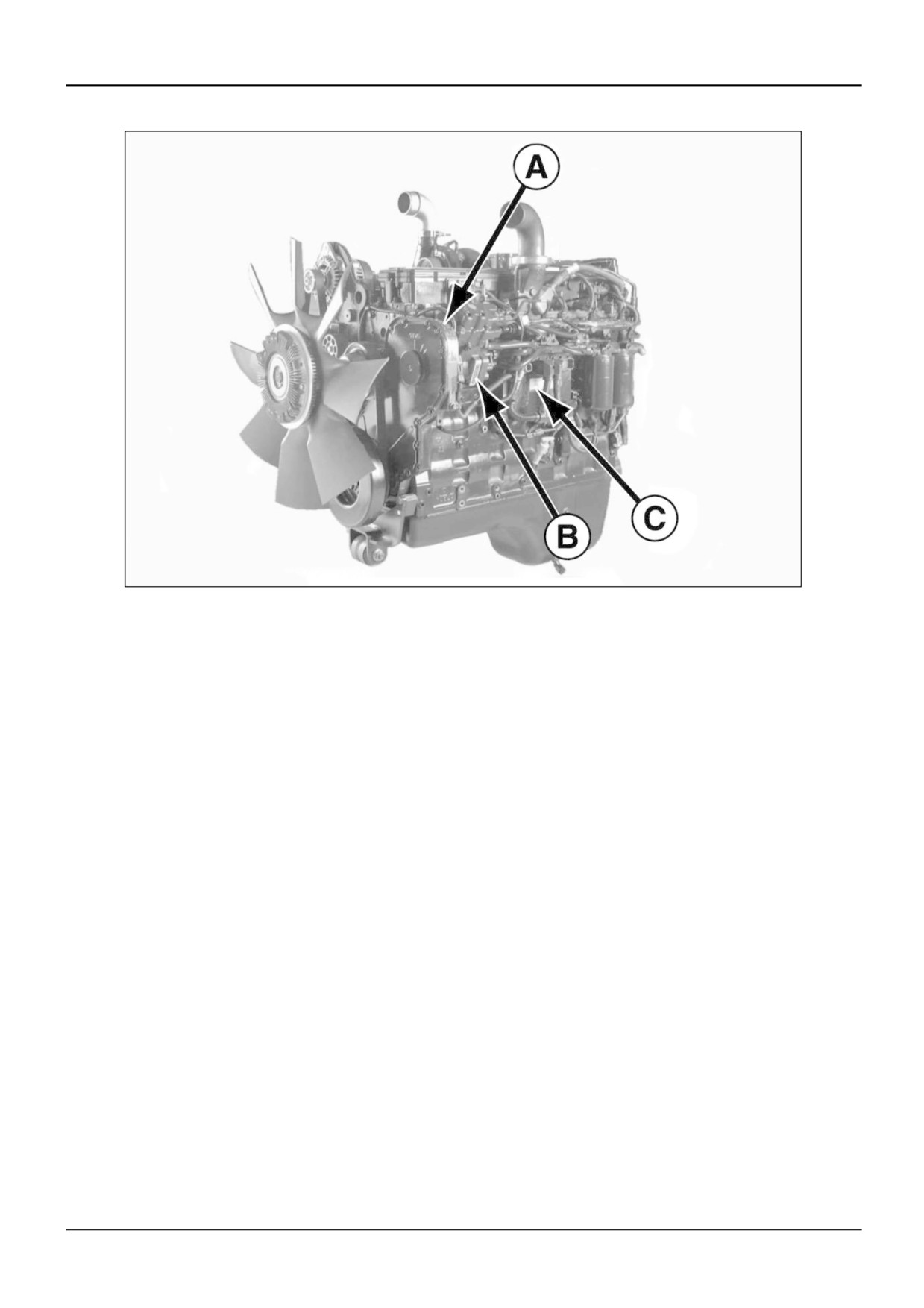
Product identification ( - A.80.A.10)
RCPH05CDC183ABA
1
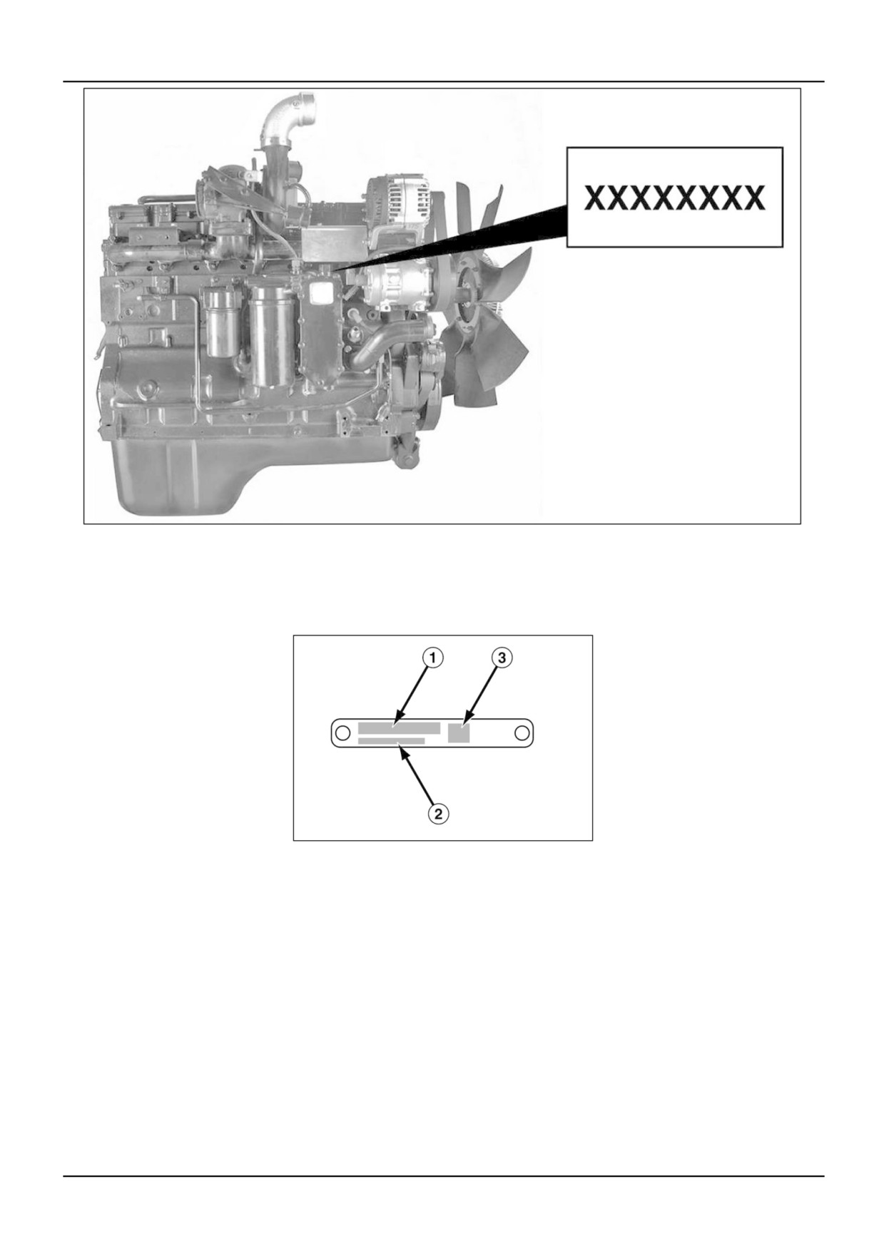
Data plate locations
A — Engine data plate
B — Fuel injection pump data plate
C — Engine control module (ECM) data plate
87515682 4 18/01/2006
21
RCIL05CDC005CAA
2
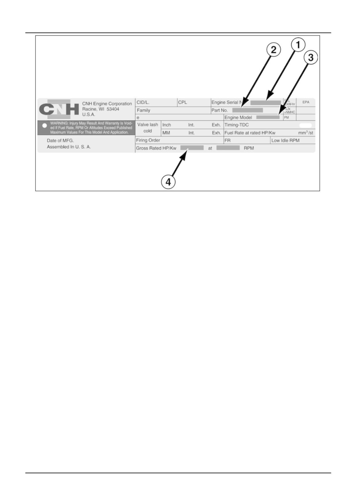
Engine data plate
1 — Engine serial number (ESN)
2 — Part number
3 — Engine model (e.g., 6TAA-8304 or 6TAA-9004)
4 — Horsepower and RPM rating
The engine data plate is located on top of the timing gear housing.
The engine data plate contains specific information about your engine. The engine serial number (ESN) and part
number are used when ordering service parts. The data plate MUST not be changed unless approved by CNH.
87515682 4 18/01/2006
22
RCPH05CDC184ABA
3
Engine serial number (ESN)
If the engine data plate is not readable, the engine serial number is also stamped into the top of the oil cooler housing.
RCIL05CDC007AAA
4
Fuel injection pump data plate
1 — Part number
2 — Pump serial number
3 — Factory code
The fuel pump data plate is located on the side of the injection pump.
87515682 4 18/01/2006
23
RCIL05CDC006CAA
5
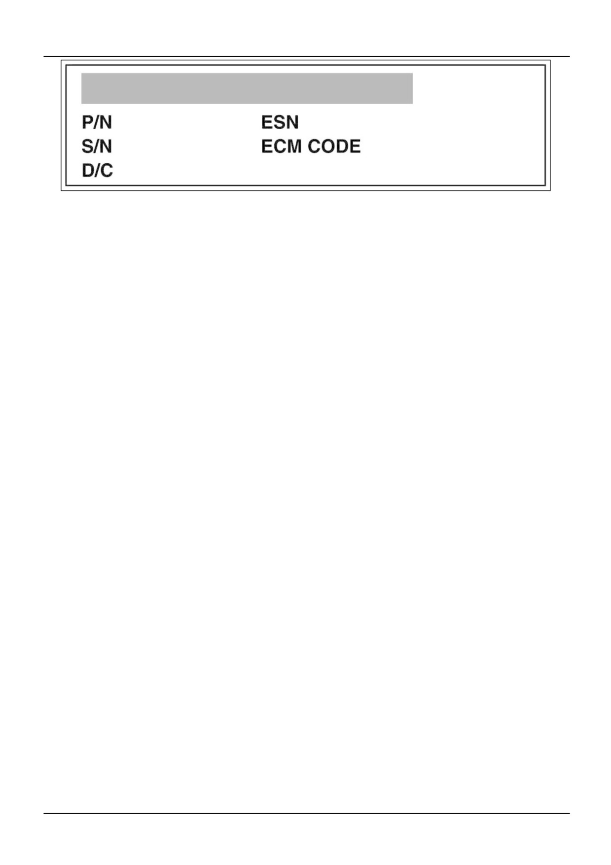
Engine control module
P/N — Part number
S/N — Serial number
D/C — Date code
ESN — Engine serial number
ECM CODE — Software programming code
The engine control module data plate is located above the module connectors on the left hand side of the engine.
The data plate contains hardware and software programming information about the control module, as well as
the engine serial number (ESN).
87515682 4 18/01/2006
24
REPAIR MANUAL
POWER PRODUCTION
TG215 , TG245 , TG275 , TG305 , TJ280 , TJ330
87515682 4 18/01/2006
B
Contents
POWER PRODUCTION - B
ENGINE
B.10.A
TG215 , TG245 , TG275 , TG305 , TJ280 , TJ330
FUEL AND INJECTION SYSTEM
B.20.A
TG215 , TG245 , TG275 , TG305 , TJ280 , TJ330
AIR INTAKE SYSTEM
B.30.A
TG215 , TG245 , TG275 , TG305 , TJ280 , TJ330
EXHAUST SYSTEM
B.40.A
TG215 , TG245 , TG275 , TG305 , TJ280 , TJ330
ENGINE COOLANT SYSTEM
B.50.A
TG215 , TG245 , TG275 , TG305 , TJ280 , TJ330
LUBRICATION SYSTEM
B.60.A
TG215 , TG245 , TG275 , TG305 , TJ280 , TJ330
STARTING SYSTEM
B.80.A
TG215 , TG245 , TG275 , TG305 , TJ280 , TJ330
87515682 4 18/01/2006
B
POWER PRODUCTION - B
ENGINE - 10.A
TG215 , TG245 , TG275 , TG305 , TJ280 , TJ330
87515682 4 18/01/2006
B.10.A / 1
Contents
POWER PRODUCTION - B
ENGINE - 10.A
TECHNICAL DATA
ENGINE - Special tools (B.10.A - D.20.A.40)
9
ENGINE - General specification (B.10.A - D.40.A.10)
10
Valve drive
Valve drive Rocker assembly - Torque (B.10.A.40.43 - D.20.A.10)
11
Valve drive Rocker assembly - Service limits (B.10.A.40.43 - D.20.A.20)
11
Valve drive Rocker assembly - Special tools (B.10.A.40.43 - D.20.A.40)
11
Rocker assembly Housing - Torque (B.10.A.40.43.05 - D.20.A.10)
12
Rocker assembly Rocker arm - Service limits (B.10.A.40.43.10 - D.20.A.20)
12
Rocker assembly Shaft - Service limits (B.10.A.40.43.20 - D.20.A.20)
12
Valve drive Camshaft - Torque (B.10.A.40.44 - D.20.A.10)
13
Valve drive Camshaft - Service limits (B.10.A.40.44 - D.20.A.20)
13
Valve drive Camshaft - Special tools (B.10.A.40.44 - D.20.A.40)
14
Camshaft Gear - Service limits (B.10.A.40.44.10 - D.20.A.20)
15
Camshaft Tappet - Service limits (B.10.A.40.44.25 - D.20.A.20)
16
Camshaft Bushing - Service limits (B.10.A.40.44.30 - D.20.A.20)
18
Camshaft Bushing - Special tools (B.10.A.40.44.30 - D.20.A.40)
19
Camshaft Journal - Service limits (B.10.A.40.44.35 - D.20.A.20)
19
Camshaft Lobe - Service limits (B.10.A.40.44.40 - D.20.A.20)
20
Valve assembly Valve - Service limits (B.10.A.40.46.10 - D.20.A.20)
23
Valve assembly Valve - Special tools (B.10.A.40.46.10 - D.20.A.40)
23
Valve assembly Spring - Service limits (B.10.A.40.46.15 - D.20.A.20)
24
Valve assembly Spring - Special tools (B.10.A.40.46.15 - D.20.A.40)
25
Crankshaft
Crankshaft - Service limits (B.10.A.43 - D.20.A.20)
26
Crankshaft - Special tools (B.10.A.43 - D.20.A.40)
26
Crankshaft Front seal - Torque (B.10.A.43.01 - D.20.A.10)
27
Crankshaft Front seal - Special tools (B.10.A.43.01 - D.20.A.40)
27
Crankshaft Rear seal - Special tools (B.10.A.43.02 - D.20.A.40)
28
Crankshaft Front wear sleeve - Special tools (B.10.A.43.05 - D.20.A.40)
28
Crankshaft Rear wear sleeve - Special tools (B.10.A.43.06 - D.20.A.40)
29
Crankshaft Gear - Service limits (B.10.A.43.10 - D.20.A.20)
29
Crankshaft Main bearing - Torque (B.10.A.43.15 - D.20.A.10)
30
Crankshaft Main bearing - Special tools (B.10.A.43.15 - D.20.A.40)
30
Crankshaft Main bearing - Service limits (B.10.A.43.15 - D.20.A.20)
32
Crankshaft Speed ring - Torque (B.10.A.43.20 - D.20.A.10)
32
87515682 4 18/01/2006
B.10.A / 2
Timing gear housing
Timing gear housing - Torque (B.10.A.46 - D.20.A.10)
34
Connecting rod and piston
Connecting rod and piston - Special tools (B.10.A.47 - D.20.A.40)
35
Connecting rod and piston Connecting rod - Torque (B.10.A.47.10 - D.20.A.10)
35
Connecting rod and piston Connecting rod - Service limits (B.10.A.47.10 - D.20.A.20)
36
Connecting rod and piston Piston - Service limits (B.10.A.47.15 - D.20.A.20)
38
Piston Ring - Service limits (B.10.A.47.15.05 - D.20.A.20)
39
Piston Pin - Service limits (B.10.A.47.15.10 - D.20.A.20)
39
Flywheel
Flywheel - Torque (B.10.A.50 - D.20.A.10)
40
Flywheel - Service limits (B.10.A.50 - D.20.A.20)
40
Flywheel - Special tools (B.10.A.50 - D.20.A.40)
41
Vibration damper
Vibration damper - Torque (B.10.A.68 - D.20.A.10)
43
Vibration damper - Service limits (B.10.A.68 - D.20.A.20)
43
Cylinder block
Cylinder block Bore - Service limits (B.10.A.70.10 - D.20.A.20)
45
Cylinder block Liner - Torque (B.10.A.70.15 - D.20.A.10)
45
Cylinder block Liner - Service limits (B.10.A.70.15 - D.20.A.20)
45
Cylinder block Liner - Special tools (B.10.A.70.15 - D.20.A.40)
47
Cylinder head
Cylinder head - Torque (B.10.A.72 - D.20.A.10)
50
Cylinder head - Service limits (B.10.A.72 - D.20.A.20)
50
Cylinder head - Special tools (B.10.A.72 - D.20.A.40)
52
Cylinder head Valve seat - Service limits (B.10.A.72.10 - D.20.A.20)
56
Cylinder head Valve guide - Service limits (B.10.A.72.15 - D.20.A.20)
56
Valve cover
Valve cover - Torque (B.10.A.74 - D.20.A.10)
58
Front cover
Front cover - Torque (B.10.A.75 - D.20.A.10)
59
Rear cover
Rear cover - Torque (B.10.A.76 - D.20.A.10)
60
Electronic control
Electronic control Control module - Torque (B.10.A.92.91 - D.20.A.10)
61
Sensing system
Sensing system Speed sensor - Torque (B.10.A.95.80 - D.20.A.10)
62
Sensing system Speed sensor - Service limits (B.10.A.95.80 - D.20.A.20)
62
Sensing system Camshaft speed sensor - Torque (B.10.A.95.82 - D.20.A.10)
62
Sensing system Camshaft speed sensor - Service limits (B.10.A.95.82 - D.20.A.20)
63
FUNCTIONAL DATA
Timing gear
Timing gear - Static description (B.10.A.45 - C.30.A.20)
64
Wiring harness
Wiring harness - Component identification (B.10.A.88 - C.40.C.20)
65
87515682 4 18/01/2006
B.10.A / 3
Sensing system
Sensing system - Component identification (B.10.A.95 - C.40.C.20)
69
SERVICE
ENGINE - Place on stand (B.10.A - F.35.A.10)
70
ENGINE - Check (B.10.A - F.40.A.11)
75
Valve drive
Valve drive Rocker assembly - Check (B.10.A.40.43 - F.40.A.11)
77
Valve drive Rocker assembly - Remove (B.10.A.40.43 - F.10.A.10)
79
Valve drive Rocker assembly - Disassemble (B.10.A.40.43 - F.10.A.25)
81
Valve drive Rocker assembly - Visual inspection (B.10.A.40.43 - F.40.A.10)
82
Valve drive Rocker assembly - Measure (B.10.A.40.43 - F.40.A.16)
84
Valve drive Rocker assembly - Assemble (B.10.A.40.43 - F.10.A.20)
85
Valve drive Rocker assembly - Install (B.10.A.40.43 - F.10.A.15)
86
Rocker assembly Housing - Remove (B.10.A.40.43.05 - F.10.A.10)
87
Rocker assembly Housing - Visual inspection (B.10.A.40.43.05 - F.40.A.10)
89
Rocker assembly Housing - Install (B.10.A.40.43.05 - F.10.A.15)
90
Rocker assembly Crosshead - Remove (B.10.A.40.43.25 - F.10.A.10)
92
Rocker assembly Crosshead - Visual inspection (B.10.A.40.43.25 - F.40.A.10)
93
Rocker assembly Crosshead - Install (B.10.A.40.43.25 - F.10.A.15)
94
Valve drive Camshaft - Preliminary test (B.10.A.40.44 - F.40.A.20)
95
Valve drive Camshaft - Remove (B.10.A.40.44 - F.10.A.10)
97
Valve drive Camshaft - Visual inspection (B.10.A.40.44 - F.40.A.10)
99
Valve drive Camshaft - Measure (B.10.A.40.44 - F.40.A.16)
100
Valve drive Camshaft - Install (B.10.A.40.44 - F.10.A.15)
102
Valve drive Camshaft - End play (B.10.A.40.44 - F.40.E.10)
104
Valve drive Camshaft - Backlash (B.10.A.40.44 - F.40.E.15)
105
Camshaft Gear - Remove (B.10.A.40.44.10 - F.10.A.10)
106
Camshaft Gear - Visual inspection (B.10.A.40.44.10 - F.40.A.10)
107
Camshaft Gear - Install (B.10.A.40.44.10 - F.10.A.15)
109
Camshaft Push rod - Remove (B.10.A.40.44.20 - F.10.A.10)
111
Camshaft Push rod - Visual inspection (B.10.A.40.44.20 - F.40.A.10)
112
Camshaft Push rod - Install (B.10.A.40.44.20 - F.10.A.15)
114
Camshaft Tappet - Remove (B.10.A.40.44.25 - F.10.A.10)
115
Camshaft Tappet - Visual inspection (B.10.A.40.44.25 - F.40.A.10)
117
Camshaft Tappet - Install (B.10.A.40.44.25 - F.10.A.15)
118
Camshaft Bushing - Remove (B.10.A.40.44.30 - F.10.A.10)
121
Camshaft Bushing - Measure (B.10.A.40.44.30 - F.40.A.16)
123
Camshaft Bushing - Install (B.10.A.40.44.30 - F.10.A.15)
124
Valve drive Valve assembly - Adjust (B.10.A.40.46 - F.45.A.01)
125
Valve drive Valve assembly - Disassemble (B.10.A.40.46 - F.10.A.25)
127
Valve assembly Valve - Cleaning (B.10.A.40.46.10 - F.30.A.10)
130
Valve assembly Valve - Visual inspection (B.10.A.40.46.10 - F.40.A.10)
131
Valve assembly Valve - Measure (B.10.A.40.46.10 - F.40.E.01)
132
87515682 4 18/01/2006
B.10.A / 4
Valve assembly Spring - Measure (B.10.A.40.46.15 - F.40.E.01)
133
Valve drive Valve assembly - Assemble (B.10.A.40.46 - F.10.A.20)
136
Crankshaft
Crankshaft - Remove (B.10.A.43 - F.10.A.10)
140
Crankshaft - Install (B.10.A.43 - F.10.A.15)
141
Crankshaft - End play (B.10.A.43 - F.40.E.10)
142
Crankshaft Front seal - Remove (B.10.A.43.01 - F.10.A.10)
143
Crankshaft Front seal - Visual inspection (B.10.A.43.01 - F.40.A.10)
145
Crankshaft Front seal - Install (B.10.A.43.01 - F.10.A.15)
146
Crankshaft Rear seal - Remove (B.10.A.43.02 - F.10.A.10)
149
Crankshaft Rear seal - Visual inspection (B.10.A.43.02 - F.40.A.10)
150
Crankshaft Rear seal - Install (B.10.A.43.02 - F.10.A.15)
151
Crankshaft Front wear sleeve - Remove (B.10.A.43.05 - F.10.A.10)
154
Crankshaft Front wear sleeve - Visual inspection (B.10.A.43.05 - F.40.A.10)
155
Crankshaft Front wear sleeve - Install (B.10.A.43.05 - F.10.A.15)
156
Crankshaft Rear wear sleeve - Remove (B.10.A.43.06 - F.10.A.10)
159
Crankshaft Rear wear sleeve - Visual inspection (B.10.A.43.06 - F.40.A.10)
162
Crankshaft Rear wear sleeve - Install (B.10.A.43.06 - F.10.A.15)
164
Crankshaft Gear - Remove (B.10.A.43.10 - F.10.A.10)
170
Crankshaft Gear - Visual inspection (B.10.A.43.10 - F.40.A.10)
171
Crankshaft Gear - Measure (B.10.A.43.10 - F.40.A.16)
172
Crankshaft Gear - Install (B.10.A.43.10 - F.10.A.15)
173
Crankshaft Main bearing - Remove (B.10.A.43.15 - F.10.A.10)
175
Crankshaft Main bearing - Visual inspection (B.10.A.43.15 - F.40.A.10)
179
Crankshaft Main bearing - Measure (B.10.A.43.15 - F.40.A.16)
180
Crankshaft Main bearing - Install (B.10.A.43.15 - F.10.A.15)
181
Crankshaft - End play (B.10.A.43 - F.40.E.10)
186
Crankshaft Journal - Measure (B.10.A.43.16 - F.40.E.01)
187
Crankshaft Speed ring - Remove (B.10.A.43.20 - F.10.A.10)
188
Crankshaft Speed ring - Visual inspection (B.10.A.43.20 - F.40.A.10)
189
Crankshaft Speed ring - Install (B.10.A.43.20 - F.10.A.15)
190
Timing gear housing
Timing gear housing - Remove (B.10.A.46 - F.10.A.10)
191
Timing gear housing - Visual inspection (B.10.A.46 - F.40.A.10)
193
Timing gear housing - Install (B.10.A.46 - F.10.A.15)
194
Connecting rod and piston
Connecting rod and piston - Remove (B.10.A.47 - F.10.A.10)
195
TJ280, TG215, TG245, TG275, TG305
Connecting rod and piston - Disassemble (B.10.A.47 - F.10.A.25)
199
TJ280, TG215, TG245, TG275, TG305
Connecting rod and piston - Assemble (B.10.A.47 - F.10.A.20)
201
TJ280, TG215, TG245, TG275, TG305
Connecting rod and piston - Install (B.10.A.47 - F.10.A.15)
204
TJ280, TG215, TG245, TG275, TG305
Connecting rod and piston - Remove (B.10.A.47 - F.10.A.10)
210
TJ330
87515682 4 18/01/2006
B.10.A / 5
Connecting rod and piston - Disassemble (B.10.A.47 - F.10.A.25)
215
TJ330
Connecting rod and piston - Assemble (B.10.A.47 - F.10.A.20)
217
TJ330
Connecting rod and piston - Install (B.10.A.47 - F.10.A.15)
221
TJ330
Connecting rod and piston Connecting rod - Visual inspection (B.10.A.47.10 - F.40.A.10)
228
Connecting rod and piston Connecting rod - Measure (B.10.A.47.10 - F.40.A.16)
230
TJ280, TG215, TG245, TG275, TG305
Connecting rod and piston Connecting rod - Measure (B.10.A.47.10 - F.40.E.01)
233
TJ330
Connecting rod Bearing - Remove (B.10.A.47.10.05 - F.10.A.10)
236
Connecting rod Bearing - Visual inspection (B.10.A.47.10.05 - F.40.A.10)
237
Connecting rod Bearing - Measure (B.10.A.47.10.05 - F.40.A.16)
239
Connecting rod Bearing - Install (B.10.A.47.10.05 - F.10.A.15)
240
Connecting rod and piston Piston - Cleaning (B.10.A.47.15 - F.30.A.10)
241
Connecting rod and piston Piston - Measure (B.10.A.47.15 - F.40.A.16)
243
TJ280, TG215, TG245, TG275, TG305
Connecting rod and piston Piston - Measure (B.10.A.47.15 - F.40.E.01)
245
TJ330
Piston Ring - Remove (B.10.A.47.15.05 - F.10.A.10)
247
Piston Ring - Measure (B.10.A.47.15.05 - F.40.A.16)
248
Piston Ring - Install (B.10.A.47.15.05 - F.10.A.15)
249
Piston Pin - Measure (B.10.A.47.15.10 - F.40.A.16)
251
Flywheel
Flywheel - Remove (B.10.A.50 - F.10.A.10)
252
Flywheel - Visual inspection (B.10.A.50 - F.40.A.10)
254
Flywheel - Install (B.10.A.50 - F.10.A.15)
256
Flywheel - Measure (B.10.A.50 - F.40.A.16)
259
Vibration damper
Vibration damper - Remove (B.10.A.68 - F.10.A.10)
261
TJ280, TG215, TG245, TG275, TG305
Vibration damper - Visual inspection (B.10.A.68 - F.40.A.10)
262
TJ280, TG215, TG245, TG275, TG305
Vibration damper - Install (B.10.A.68 - F.10.A.15)
264
TJ280, TG215, TG245, TG275
Vibration damper - Remove (B.10.A.68 - F.10.A.10)
265
TJ330
Vibration damper - Visual inspection (B.10.A.68 - F.40.A.10)
266
TJ330
Vibration damper - Install (B.10.A.68 - F.10.A.15)
268
TJ330
Cylinder block
Cylinder block - Cleaning (B.10.A.70 - F.30.A.10)
269
Cylinder block - Measure (B.10.A.70 - F.40.A.16)
270
Cylinder block Bore - Measure (B.10.A.70.10 - F.40.A.16)
271
Cylinder block Liner - Preliminary test (B.10.A.70.15 - F.40.A.20)
272
Cylinder block Liner - Remove (B.10.A.70.15 - F.10.A.10)
275
Cylinder block Liner - Visual inspection (B.10.A.70.15 - F.40.A.10)
277
87515682 4 18/01/2006
B.10.A / 6
Cylinder block Liner - Measure (B.10.A.70.15 - F.40.A.16)
281
Cylinder block Liner - Install (B.10.A.70.15 - F.10.A.15)
282
Cylinder block Liner - Measure (B.10.A.70.15 - F.40.A.16)
288
Cylinder head
Cylinder head - Remove (B.10.A.72 - F.10.A.10)
292
Cylinder head - Disassemble (B.10.A.72 - F.10.A.25)
294
Cylinder head - Cleaning (B.10.A.72 - F.30.A.10)
297
Cylinder head - Visual inspection (B.10.A.72 - F.40.A.10)
299
Cylinder head - Measure (B.10.A.72 - F.40.A.16)
301
Cylinder head - Pressure test (B.10.A.72 - F.40.A.30)
303
Cylinder head Valve seat - Vacuum test (B.10.A.72.10 - F.40.A.25)
306
Cylinder head Valve guide - Cleaning (B.10.A.72.15 - F.30.A.10)
307
Cylinder head Valve guide - Measure (B.10.A.72.15 - F.40.A.16)
308
Cylinder head - Assemble (B.10.A.72 - F.10.A.20)
310
Cylinder head - Install (B.10.A.72 - F.10.A.15)
313
Valve cover
Valve cover - Remove (B.10.A.74 - F.10.A.10)
315
Valve cover - Visual inspection (B.10.A.74 - F.40.A.10)
316
Valve cover - Install (B.10.A.74 - F.10.A.15)
317
Front cover
Front cover - Remove (B.10.A.75 - F.10.A.10)
318
Front cover - Visual inspection (B.10.A.75 - F.40.A.10)
319
Front cover - Install (B.10.A.75 - F.10.A.15)
320
Rear cover
Rear cover - Remove (B.10.A.76 - F.10.A.10)
323
Rear cover - Install (B.10.A.76 - F.10.A.15)
325
Wiring harness
Wiring harness - Disconnect (B.10.A.88 - F.10.A.11)
326
Wiring harness - Connect (B.10.A.88 - F.10.A.16)
327
Electronic control
Electronic control - Check (B.10.A.92 - F.40.A.11)
328
Electronic control Control module - Remove (B.10.A.92.91 - F.10.A.10)
330
Electronic control Control module - Install (B.10.A.92.91 - F.10.A.15)
333
Sensing system
Sensing system Speed sensor - Remove (B.10.A.95.80 - F.10.A.10)
336
Sensing system Speed sensor - Visual inspection (B.10.A.95.80 - F.40.A.10)
337
Sensing system Speed sensor - Test (B.10.A.95.80 - F.40.C.01)
338
Sensing system Speed sensor - Install (B.10.A.95.80 - F.10.A.15)
339
Sensing system Camshaft speed sensor - Remove (B.10.A.95.82 - F.10.A.10)
340
Sensing system Camshaft speed sensor - Visual inspection (B.10.A.95.82 - F.40.A.10)
341
Sensing system Camshaft speed sensor - Test (B.10.A.95.82 - F.40.C.01)
342
Sensing system Camshaft speed sensor - Install (B.10.A.95.82 - F.10.A.15)
343
DIAGNOSTIC
ENGINE - Problem solving (B.10.A - G.40.A.30)
344
87515682 4 18/01/2006
B.10.A / 7
ENGINE - Testing (B.10.A - G.40.A.20)
347
ENGINE - Problem solving (B.10.A - G.40.A.30)
350
87515682 4 18/01/2006
B.10.A / 8
PO
ENGINE - Special tools (B.10.A - D.20.A.40)
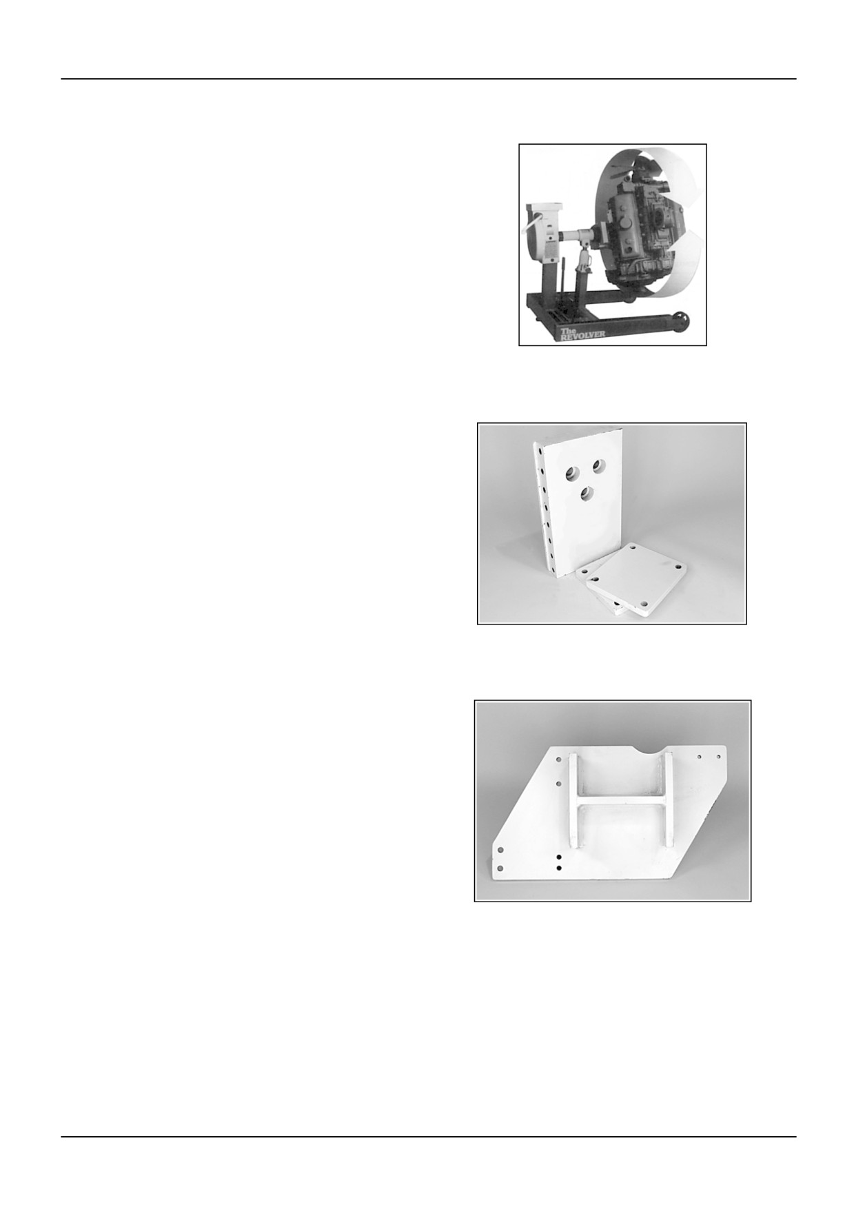
The Revolver® engine repair stand - OEM4137
The Revolver® includes OEM205061 which permits use
of engine mounting plates. Engine capacity: 2,722 kg
(6000 lb).
RCSC05CDC137AAA
1
Universal engine adapter - OEM205061 (SPX)
This assembly, included with OEM4137, is required to
add engine mounting plates to The Revolver®.
RCPH05CDC996AAC
2
Engine mounting plate - OEM218099 (SPX)
This plate is bolted to the CNH “C” Series engines so the
engine can be installed on The Revolver® engine repair
stand, OEM4137.
RCPH05CDC121AAA
3
87515682 4 18/01/2006
B.10.A / 9