NEW HOLLAND TD5.85 / TD5.95 / TD5.105 / TD5.115 Tractor. SERVICE MANUAL (September 2017)
SERVICE MANUAL
TD5.85 / TD5.95 / TD5.105 / TD5.115
Tractor
Part number 48194617
English
September 2017
Link Product / Engine
Product
Market Product
Engine
TD5.105 TD5.105 CAB 4WD
Europe
F5DFL413J*A001
TD5.105 TD5.105 ROPS 4WD
Europe
F5DFL413J*A001
TD5.115 TD5.115 CAB 4WD
Europe
F5DFL413H*A002
TD5.115 TD5.115 ROPS 4WD
Europe
F5DFL413H*A002
TD5.85 TD5.85 ROPS 4WD
Europe
F5DFL413L*A001
TD5.85 TD5.85 CAB 4WD
Europe
F5DFL413L*A001
TD5.95 TD5.95 CAB 2WD
Europe
F5DFL413K*A001
TD5.95 TD5.95 ROPS 4WD
Europe
F5DFL413K*A001
TD5.95 TD5.95 CAB 4WD
Europe
F5DFL413K*A001
4819461727/09/2017
Contents
INTRODUCTION
Engine
10
[10.501] Exhaust Gas Recirculation (EGR) exhaust treatment
10.1
Clutch
18
[18.110] Clutch and components
18.1
Transmission
21
[21.114] Mechanical transmission
21.1
[21.140] Mechanical transmission internal components
21.2
[21.112] Power shuttle transmission
21.3
[21.154] Power shuttle transmission internal components
21.4
[21.120] Gearbox
21.5
[21.160] Creeper
21.6
[21.162] Reverser
21.7
Four-Wheel Drive (4WD) system
23
[23.202] Electro-hydraulic control
23.1
Front axle system
25
[25.100] Powered front axle
25.1
[25.102] Front bevel gear set and differential
25.2
[25.108] Final drive hub, steering knuckles, and shafts
25.3
[25.400] Non-powered front axle
25.4
Rear axle system
27
[27.100] Powered rear axle
27.1
[27.106] Rear bevel gear set and differential
27.2
[27.124] Final drive hub, steering knuckles, and shafts
27.3
Power Take-Off (PTO)
31
[31.101] Rear mechanical control
31.1
4819461727/09/2017
Brakes and controls
33
[33.202] Hydraulic service brakes
33.1
[33.220] Trailer brake hydraulic control
33.2
[33.224] Trailer brake pneumatic control
33.3
Hydraulic systems
35
[35.000] Hydraulic systems
35.1
[35.104] Fixed displacement pump
35.2
[35.525] Auxiliary hydraulic valves and lines
35.3
[35.100] Main lift system
35.4
Steering
41
[41.200] Hydraulic control components
41.1
[41.206] Pump
41.2
[41.216] Cylinders
41.3
Wheels
44
[44.511] Front wheels
44.1
Cab climate control
50
[50.200] Air conditioning
50.1
Electrical systems
55
[55.000] Electrical system
55.1
[55.100] Harnesses and connectors
55.2
[55.525] Cab engine controls
55.3
[55.015] Engine control system
55.4
[55.201] Engine starting system
55.5
[55.301] Alternator
55.6
[55.302] Battery
55.7
[55.202] Cold start aid
55.8
[55.011] Fuel tank system
55.9
[55.010] Fuel injection system
55.10
4819461727/09/2017
[55.014] Engine intake and exhaust system
55.11
[55.013] Engine oil system
55.12
[55.640] Electronic modules
55.13
[55.024] Transmission control system
55.14
[55.048] Rear Power Take-Off (PTO) control system
55.15
[55.049] Front Power Take-Off (PTO) control system
55.16
[55.512] Cab controls
55.17
[55.130] Rear three-point hitch electronic control system
55.18
[55.408] Warning indicators, alarms, and instruments
55.19
Platform, cab, bodywork, and decals
90
[90.150] Cab
90.1
4819461727/09/2017
48194617 27/09/2017
INTRODUCTION
48194617 27/09/2017
1
Contents
INTRODUCTION
Note to the Owner
3
Safety rules
5
Consumables
8
48194617 27/09/2017
2
INTRODUCTION
Note to the Owner
General instructions
Important notice
All maintenance and repair operations described in this manual should be carried out exclusively by the NEW HOL-
LAND authorised workshops. All instructions detailed should be carefully observed and special equipment indicated
should be used if necessary.
Everyone who carries out service operations described without carefully observing these prescriptions will be directly
responsible of deriving damages.
Shimming
At each adjustment, select adjusting shims, measure them individually using a micrometer and then sum up recorded
values. Do not rely on measuring the whole shimming set, which may be incorrect, or on rated value indicated for
each shim.
Rotating shaft seals
To correctly install rotating shaft seals, observe the following instructions:
• Let the seal soak into the same oil as it will seal for at least half an hour before mounting.
• Thoroughly clean the shaft and ensure that the shaft working surface is not damaged.
• Place the sealing lip towards the fluid. In case of a hydrodynamic lip, consider the shaft rotation direction and orient
grooves in order that they deviate the fluid towards the inner side of the seal.
• Coat the sealing lip with a thin layer of lubricant (oil rather than grease) and fill with grease the gap between the
sealing lip and the dust lip of double lip seals.
• Insert the seal into its seat and press it down using a flat punch. Do no tap the seal with a hammer or a drift.
• Take care to insert the seal perpendicularly to its seat while you are pressing it. Once the seal is settled, ensure
that it contacts the thrust element if required.
• To prevent damaging the sealing lip against the shaft, place a suitable protection during installation.
O-rings
Lubricate the O-rings before inserting them into their seats. This will prevent the O-rings from rolling over and twine
during mounting which will jeopardise sealing.
Sealers
Apply one of the following sealers: RTV SILMATE, RHODORSIL CAF 1, or LOCTITE® PIASTIC GASKET over the mating
surfaces marked with an X.
Before applying the sealer, prepare the surface as follows:
• Remove possible scales using a metal brush.
• Thoroughly degrease the surfaces using one of the following cleaning agent: trichlorethylene, petrol or a water and
soda solution.
Bearings
It is advisable to heat the bearings to 80 - 90 °C (176 - 194 °F) before mounting them on their shafts and cool them
down before inserting them into their seats with external tapping.
Roll pins
When fitting straight roll pins, ensure that the pin notch is oriented in the direction of the effort to stress the pin. Coil
roll pins can be installed in any position.
48194617 27/09/2017
3
INTRODUCTION
Notes for spare parts
Use exclusively genuine NEW HOLLAND spare parts.
Only genuine parts guarantee same quality, life, safety as original components as they are the same as mounted in
production.
Only the NEW HOLLAND genuine spare parts can offer this guarantee.
All spare parts orders should be complete with the following data:
• Tractor model (commercial name) and frame number.
• Engine type and number.
• Part number of the ordered part, which can be found on the “Microfiches” or the “Spare parts catalogue”, which is
the base for order processing.
Notes for equipment
Equipment which NEW HOLLAND proposes and shows in this manual are as follows:
• Studied and designed expressly for use on NEW HOLLAND tractors.
• Necessary to make a reliable repair.
• Accurately built and strictly tested to offer efficient and long-lasting working means.
We also remind the repair personnel that having these equipment means:
• Work in optimal technical conditions.
• Obtain best results.
• Save time and effort.
• Work more safely.
Notices
Wear limits indicated for some details should be intended as advised, but not binding values. The words “front”, “rear”,
“right hand”, and “left hand” referred to the different parts should be intended as seen from the operator’s seat oriented
to the normal sense of movement of the tractor.
How to move the tractor with the battery removed
Cables from the external power supply should be connected exclusively to the respective terminals of the tractor
positive and negative cables using pliers in good condition which allow proper and steady contact.
Disconnect all services (lights, wind-shield wipers, etc.) before starting the tractor
If it is necessary to check the tractor electrical system, check it only with the power supply connected. At check end,
disconnect all services and switch the power supply Off before disconnecting the cables.
48194617 27/09/2017
4
INTRODUCTION
Safety rules
Pay attention to this symbol
This warning symbol points out important messages involving personal safety. Carefully read the
safety rules contained herein and follow advised precautions to avoid potential hazards and safeguard
your safety and personal integrity. In this manual you will find this symbol together with the following
key-words:
WARNING - It gives warning about improper repair operations and deriving potential consequences
affecting the service technician’s personal safety.
DANGER - It gives specific warning about potential dangers for personal safety of the operator or other
persons directly or indirectly involved.
To prevent accidents
Most accidents and personal injuries taking place in workshops are due from non-observance of some simple and
essential prudential rule and safety precautions. For this reason, IN MOST CASES THEY CAN BE AVOIDED. It
suffices to foresee possible causes and act consequently with necessary caution and care.
The possibility that an accident might occur with any type of machines should not be disregarded, no matter how well
the machine in question was designed and built.
A wise and careful service technician is the best precautions against accidents.
Careful observance of this only basic precaution would be enough to avoid many severe accidents.
DANGER: Never carry out any cleaning, lubrication or maintenance operations when the engine is running.
Safety rules
Generalities
•
Carefully follow specified repair and maintenance procedures.
•
Do not wear rings, wristwatches, jewels, unbuttoned or flapping clothing such as ties, torn clothes, scarves, open
jackets or shirts with open zips which could get hold into moving parts. We advise to use approved safety clothing
such as anti-slipping footwear, gloves, safety goggles, helmets, etc.
•
Never carry out any repair on the machine if someone is sitting on the operator’s seat, except if they are certified
operators to assist in the operation to be carried out.
•
Never operate the machine or use attachments from a place other than sitting at the operator’s seat.
•
Never carry out any operation on the machine when the engine is running, except when specifically indicated.
•
Stop the engine and ensure that all pressure is relieved from hydraulic circuits before removing caps, covers, valves,
etc.
•
All repair and maintenance operations should be carried out with the greatest care and attention.
•
Service stairs and platforms used in a workshop or in the field should be built in compliance with the safety rules in
force.
•
Disconnect the batteries and label all controls to warn that the tractor is being serviced. Block the machine and all
equipment which should be raised.
•
Never check or fill fuel tanks and accumulator batteries, nor use starting liquid if you are smoking or near open
flames as such fluids are flammable.
•
Brakes are inoperative when they are manually released for maintenance purposes. In such cases, the machine
should be kept constantly under control using blocks or similar devices.
•
The fuel filling gun should remain always in contact with the filler neck. Maintain this contact until the fuel stops
flowing into the tank to avoid possible sparks due to static electricity buildup.
•
Use exclusively specified towing points for towing the tractor. Connect parts carefully. Ensure that foreseen pins
and/or locks are steadily fixed before applying traction. Do not stop near towing bars, cables or chains working
under load.
48194617 27/09/2017
5
INTRODUCTION
•
To transfer a failed tractor, use a trailer or a low loading platform trolley if available.
•
To load and unload the machine from the transportation mean, select a flat area providing a firm support to the
trailer or truck wheels. Firmly tie the machine to the truck or trailer platform and block wheels as required by the
forwarder.
•
For electrical heaters, battery-chargers and similar equipment use exclusive auxiliary power supplies with a efficient
ground to avoid electrical shock hazard.
•
Always use lifting equipment and similar of appropriate capacity to lift or move heavy components.
•
Pay special attention to bystanders.
•
Never pour gasoline or diesel oil into open, wide and low containers.
•
Never use gasoline, diesel oil or other flammable liquids as cleaning agents. Use nonflammable nontoxic propri-
etary solvents.
•
Wear protection goggles with side guards when cleaning parts using compressed air.
•
Do not exceed a pressure of 2.1 bar (30.45 psi), in accordance with local regulations.
•
Do not run the engine in a closed building without proper ventilation.
•
Do not smoke, use open flames, cause sparks in the nearby area when filling fuel or handling highly flammable
liquids.
•
Do not use flames as light sources when working on a machine or checking for leaks.
•
Move with caution when working under a tractor, and also on or near a tractor. Wear proper safety accessories:
helmets, goggles and special footwear.
•
During checks which should be carried out with the engine running, ask an assistant to seat at the operator’s seat
and keep the service technician under visual control at any moment.
•
In case of operations outside the workshop, drive the tractor to a flat area and block it. If working on an incline
cannot be avoided, first block the tractor carefully. Move it to a flat area as soon as possible with a certain extent
of safety.
•
Ruined or plied cables and chains are unreliable. Do not use them for lifting or trailing. Always handle them wearing
gloves of proper thickness.
•
Chains should always be safely fastened. Ensure that fastening device is strong enough to hold the load foreseen.
No persons should stop near the fastening point, trailing chains or cables.
•
The working area should be always kept CLEAN and DRY. Immediately clean any spillage of water or oil.
•
Do not pile up grease or oil soaked rags, as they constitute a great fire hazard. Always place them into a metal
container. Before starting the tractor or its attachments, check, adjust and block the operator’s seat. Also ensure
that there are no persons within the tractor or attachment operating range.
•
Do not keep into your pockets any object which might fall unobserved into the tractor’s inner compartments.
•
Whenever there is the possibility of being reached by ejected metal parts or similar, use protection eye mask or
goggles with side guards, helmets, special footwear and heavy gloves.
•
Wear suitable protection such as tinted eye protection, helmets, special clothing, gloves and footwear whenever it is
necessary to carry out welding procedures. All persons standing in the vicinity of the welding process should wear
tinted eye protection. NEVER LOOK AT THE WELDING ARC IF YOUR EYES ARE NOT SUITABLY PROTECTED.
•
Metal cables with the use get frayed. Always wear adequate protections (heavy gloves, eye protection, etc.)
•
Handle all parts with the greatest caution. Keep your hands and fingers far from gaps, moving gears and similar.
Always use approved protective equipment, such as eye protection, heavy gloves and protective footwear.
Start up
• Never run the engine in confined spaces which are not equipped with adequate ventilation for exhaust gas extrac-
tion.
• Never bring your head, body, arms, legs, feet, hands, fingers near fans or rotating belts.
48194617 27/09/2017
6
INTRODUCTION
Engine
• Always loosen the radiator cap very slowly before removing it to allow pressure in the system to dissipate. Coolant
should be topped up only when the engine is stopped or idle if hot.
• Do not fill up fuel tank when the engine is running, mainly if it is hot, to avoid ignition of fires in case of fuel spilling.
• Never check or adjust the fan belt tension when the engine is running. Never adjust the fuel injection pump when
the tractor is moving.
• Never lubricate the tractor when the engine is running.
Electrical systems
• If it is necessary to use auxiliary batteries, cables must be connected at both sides as follows: (+) to (+) and (-) to
(-). Avoid short circuiting the terminals. GAS RELEASED FROM BATTERIES IS HIGHLY FLAMMABLE. During
charging, leave the battery compartment uncovered to improve ventilation. Avoid checking the battery charge by
means of “jumpers” made by placing metallic objects across the terminals. Avoid sparks or flames near the battery
area. Do no smoke to prevent explosion hazards.
• Prior to any service, check for fuel or current leaks. Remove these leaks before going on with the work.
• Do not charge batteries in confined spaces. Ensure that ventilation is appropriate to prevent accidental explosion
hazard due to build up of gases releaved during charging.
• Always disconnect the batteries before performing any type of service on the electrical system.
Hydraulic systems
• Some fluid slowly coming out from a very small port can be almost invisible and be strong enough to penetrate the
skin. For this reason, NEVER USE YOUR HANDS TO CHECK FOR LEAKS, but use a piece of cardboard or a
piece of wood to this purpose. If any fluid is injected into the skin, seek medical aid immediately. Lack of immediate
medical attention, serious infections or dermatosis may result.
• Always take system pressure readings using the appropriate gauges.
Wheels and tires
• Check that the tires are correctly inflated at the pressure specified by the manufacturer. Periodically check possible
damages to the rims and tires.
• Keep off and stay at the tire side when correcting the inflation pressure.
• Check the pressure only when the tractor is unloaded and tires are cold to avoid wrong readings due to over-
pressure. Do not reuse parts of recovered wheels as improper welding, brazing or heating may weaken the wheel
and make it fail.
• Never cut, nor weld a rim with the inflated tire assembled.
• To remove the wheels, block both front and rear tractor wheels. Raise the tractor and install safe and stable supports
under the tractor in accordance with regulations in force.
• Deflate the tire before removing any object caught into the tire tread.
• Never inflate tires using flammable gases as they may originate explosions and cause injuries to bystanders.
Removal and installation
• Lift and handle all heavy components using lifting equipment of adequate capacity. Ensure that parts are supported
by appropriate slings and hooks. Use lifting eyes provided to this purpose. Take care of the persons near the loads
to be lifted.
• Handle all parts with great care. Do not place your hands or fingers between two parts. Wear approved protective
clothing such as safety goggles, gloves and footwear.
• Do not twine chains or metal cables. Always wear protection gloves to handle cables or chains.
48194617 27/09/2017
7

INTRODUCTION
Consumables
COMPONENT TO BE FILLED
QUANTITY
RECOM-
INTERNA-
OR TOPPED UP
MENDED
TIONAL SPECI-
PRODUCTS
FICATION
liters/dm3
US gal
Cooling system:
NEW HOLLAND
without cab:
14
3.7
AMBRA
with cab:
16
4.2
ACTIFULL™ OT
-
EXTENDED LIFE
COOLANT
Windscreen washer bottle
2
0.53
Water & cleaning
-
liquid
Fuel tank.
121
29.06
Decanted and
-
filtered diesel fuel
Engine sump:
NEW HOLLAND
8.5
2.25
AMBRA UNITEK
MASTERGOLD
SBL CJ-4 SAE
10W-40 or
API CJ-4
NEW HOLLAND
ACEA E7 ACEA E9
AMBRA UNITEK
MASTERGOLD
SSL CJ-4 SAE
0W-40
Brake control circuit
NEW HOLLAND
0.4
0.11
AMBRA BRAKE
ISO 7308
LHM NH 610 A
Front axle:
- axle housing:
7.0
1.8
NEW HOLLAND
- final drives (each):
1.25
0.3
AMBRA MULTI
API GL-4
Rear transmission (bevel drive and
G™ HYDRAULIC
ISO 32/46
brakes), gearbox, hydraulic lift and
46
12.15
TRANSMISSION
SAE 10W - 30
PTO
OIL NH 410B
Rear final drives (each)
5.3
1.40
Front wheel hubs
-
-
Grease NEW
Grease fittings
HOLLAND
AMBRA GR-9
NLGI 2
-
-
MULTI-PURPOSE
GREASE
NOTICE: Use only heavy-duty, low silicate coolant such as NEW HOLLAND AMBRA ACTIFULL™ OT EXTENDED
LIFE COOLANT anti-freeze. Automotive antifreeze purchased at local supply store outlets most likely is not low
silicate and must not be used in heavy-duty diesel engines. Always have a minimum of 50% ethylene glycol coolant in
the cooling system, adjusting the concentration based on ambient temperature, according to coolant label instructions.
Use good quality water. Deionized water is ideal for cooling systems and is contained in some prepackaged coolants
labeled as pre-mixed with water. If the low silicate ethylene glycol coolant is not pre-charged with supplemental diesel
coolant additive/inhibitor, this must be added to the solution to provide protection against corrosion and pitting.
48194617 27/09/2017
8
SERVICE MANUAL
Engine
TD5.105
TD5.115
TD5.85
TD5.95
48194617 27/09/2017
10
Contents
Engine - 10
[10.501] Exhaust Gas Recirculation (EGR) exhaust treatment
10.1
48194617 27/09/2017
10
Engine - 10
Exhaust Gas Recirculation (EGR) exhaust treatment - 501
TD5.105
TD5.115
TD5.85
TD5.95
48194617 27/09/2017
10.1 [10.501] / 1
Contents
Engine - 10
Exhaust Gas Recirculation (EGR) exhaust treatment - 501
TECHNICAL DATA
Diesel Particulate Filters (DPF)
Torque
3
General specification
4
FUNCTIONAL DATA
Diesel Particulate Filters (DPF)
Dynamic description
6
SERVICE
Diesel Particulate Filters (DPF)
Remove
11
Install
14
Remove - with support
17
DIAGNOSTIC
Exhaust Gas Recirculation (EGR) exhaust treatment
3710 - Lambda sensor - signal not plausible [ECU]
21
3766 - Diesel particulate filter pressure sensor: Fault check for the pressure sensor plausibility
24
3796 - Diesel particulate filter pressure sensor hose line error
25
3825 - Short circuit over load error for H-bridge [ECU]
26
48194617 27/09/2017
10.1 [10.501] / 2
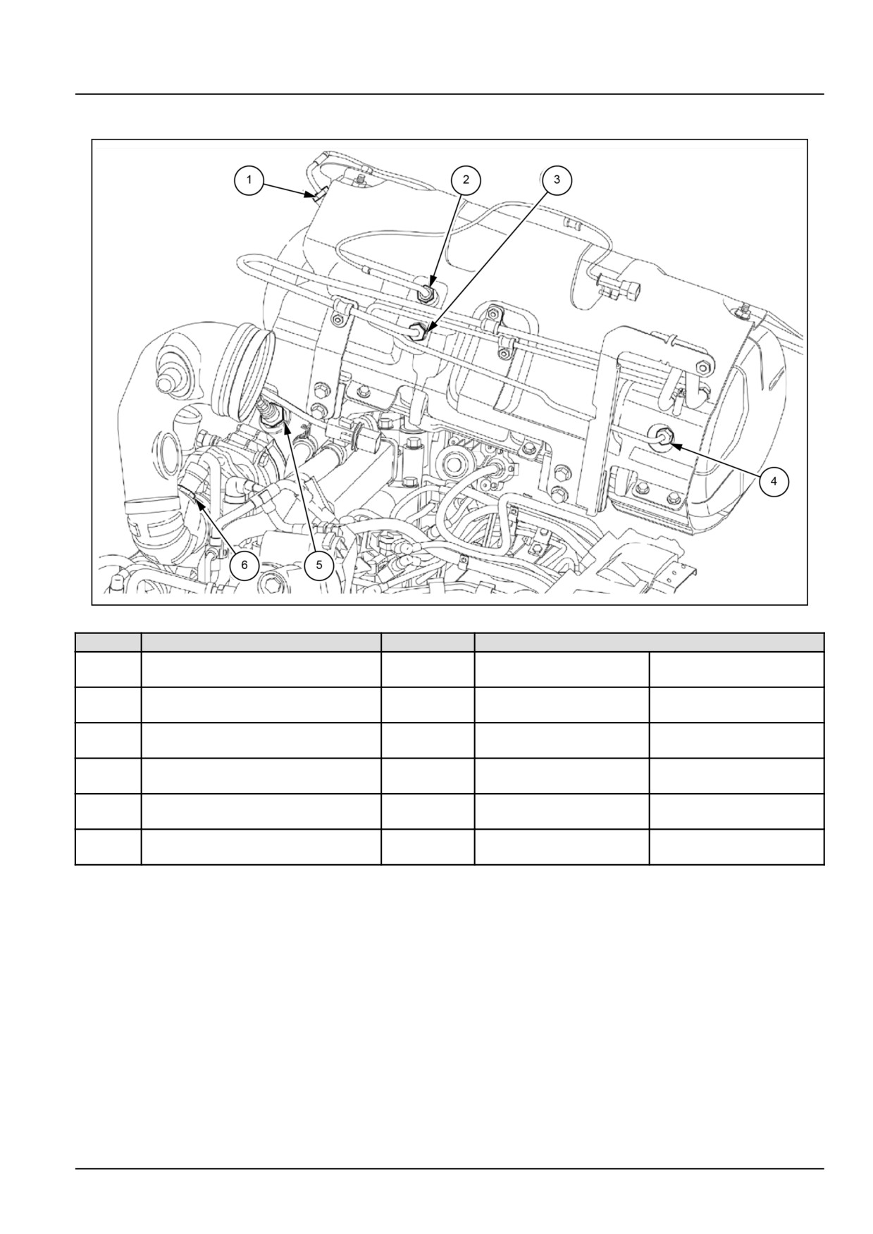
Engine - Exhaust Gas Recirculation (EGR) exhaust treatment
Diesel Particulate Filters (DPF) - Torque
ANIL15TRO1984FB
1
No
Part to tighten
Thread size
Torque settings
Gas temperature sensor on DPF
40.50 - 49.50 N·m
4.14 - 5.12 kg
1.
M14 x 1.5
intake
(29.87 - 36.51 lb ft)
(9.13 - 11.29 lb)
DPF filter first section temperature
40.50 - 49.50 N·m
4.14 - 5.12 kg
2.
M14 x 1.5
sensor
(29.87 - 36.51 lb ft)
(9.13 - 11.29 lb)
40.50 - 49.50 N·m
4.14 - 5.12 kg
3.
Pressure pipe fitting on turbine side
M14 x 1.5
(29.87 - 36.51 lb ft)
(9.13 - 11.29 lb)
27.00 - 33.00 N·m
2.80 - 3.42 kg
4.
Pressure pipe fitting on muffler side
M12 x 1.5
(19.91 - 24.34 lb ft)
(6.17 - 7.54 lb)
45.00 - 55.00 N·m
4.66 - 5.70 kg
5.
Lambda sensor
M18 x 1.5
(33.19 - 40.57 lb ft)
(10.27 - 12.57 lb)
15.00 - 25.00 N·m
1.55 - 2.59 kg
6.
Air temperature sensor
M12 x 1.5
(11.06 - 18.44 lb ft)
(3.42 - 5.71 lb)
48194617 27/09/2017
10.1 [10.501] / 3
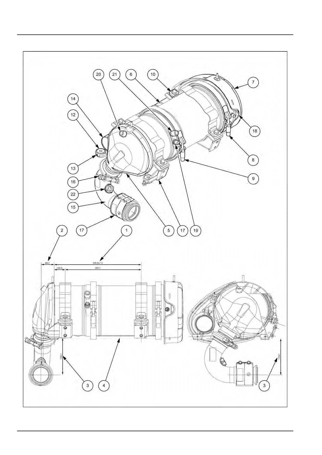
Engine - Exhaust Gas Recirculation (EGR) exhaust treatment
Diesel Particulate Filters (DPF) - General specification
ANIL15TRO1985HB
1
Measurements to respect for installing the filter - Legend of components - Legend of sensor fixing holes:
48194617 27/09/2017
10.1 [10.501] / 4