Model 795BBHD 115 Gallon Preservative Applicator New Holland & Case IH BB High Density Baler. Installation Manual (2011)
Installation Manual
Model 795BBHD
115 Gallon Preservative Applicator
New Holland & Case IH BB High Density Baler
795BBHD-20-INST (Imp&Metric)
11/21
1
Table of Contents
Harvest Tec Model 795BBHD Installation
Introduction
4
Installation of Applicator
5-20
Installation of Tank
5-6
Installation of Pump Plate
6
Installation of Drain/Fill Line
7
Installation of Spray Shield
8
Wind Guard Installation
9
Mounting Solenoids and Hose Routing
10
Main Wire Harness and Baler Interface Harness Routing
11
Installation of Star Wheels
12
Installation End of Bale Sensor
13
Tractor Setup
14
Display Installations
15-19
Harvest Tec Display
15
Tablet Display
15
Baler Display
16-19
Wiring Diagram
20
Pin Outs
21-23
Parts Breakdown
24-34
Tank, Saddle and Saddle Legs
24
Pump Manifold
25
Star Wheel Moisture Sensor
26
Control Boxes and Wiring Harnesses
27
Solenoid Package
28
Hose and Drain / Fill Line
29
Optional iPad Mini Mounting Kit
30
Optional iPad Display Kit
31
Optional Harvest Tec Display Kit
32
4636C Install Kit
33
Wing Guard Assembly
34
Rear Light Camera Bracket
34
Warranty Statement
35
3
Introduction
Thank you for purchasing the 795BBHD Hay Preservative Applicator System. This applicator system has been
designed to plug directly into the baler’s ISOBUS and display on the New Holland Intelliview 3 or Intelliview 4,
Case Pro 300 or Pro 700. As well as the option of operation through an Apple iPad or Android Tablet (not
included) using the Precision Baling App. Found in iTunes store or Google Play Stores for free. The
Preservative Applicator System offers these advantages:
1. Operation coordinated with baler operation
2. Less cab clutter providing better visibility
3. Ease of use with all information on one screen
4. Records kept together
5. The system is ready for future updates
The 795BBHD Hay Preservative Applicator System is designed to apply buffered propionic acid to the forage
crop as it is baled. The 795BBHD Applicator will adjust the rate of application based on moisture and tonnage
of the crop being harvested. This manual will take you through the steps of installing the applicator. Please
read this manual carefully to learn how to install the equipment correctly. Failure to do this can result in
personal injury or equipment malfunction. If you are unsure about installing the system after consulting this
manual, contact your local authorized dealership for additional assistance or look for the contact information on
the back cover of this manual. If you are in need of parts for the system, please view the Parts Breakdown
toward the back of this manual and contact your local authorized dealer to order the parts. This applicator is
designed to apply Crop Saver and Thirty Plus buffered propionic acid.
Right and Left sides are determined by facing in the direction of forward travel.
*Made for iPad® (3rd through Pro 2nd generation), running the current iOS operating system
or one version previous required for iPad option
*iPad is a trademark of Apple Inc., registered in the U.S. and other countries.
*Hay App version must be at least 2.7.1 (or higher) to operate with the iPad Integration Module
System Requirements
CNH Baler Monitor must have version 4.2.0 or higher
*Made for Harvest Tec Display, Baler Integration, or Tablet*
For best performance ensure all displays are running the latest operating system.
Tools Needed:
- Standard wrench set
- Electric drill and bits
- Side cutter
- Crescent wrench
- Standard screwdriver
- Standard nut driver set
- Standard socket set
- Hammer
- Metal cutting tools
- Hose cutter
- Center punch
4
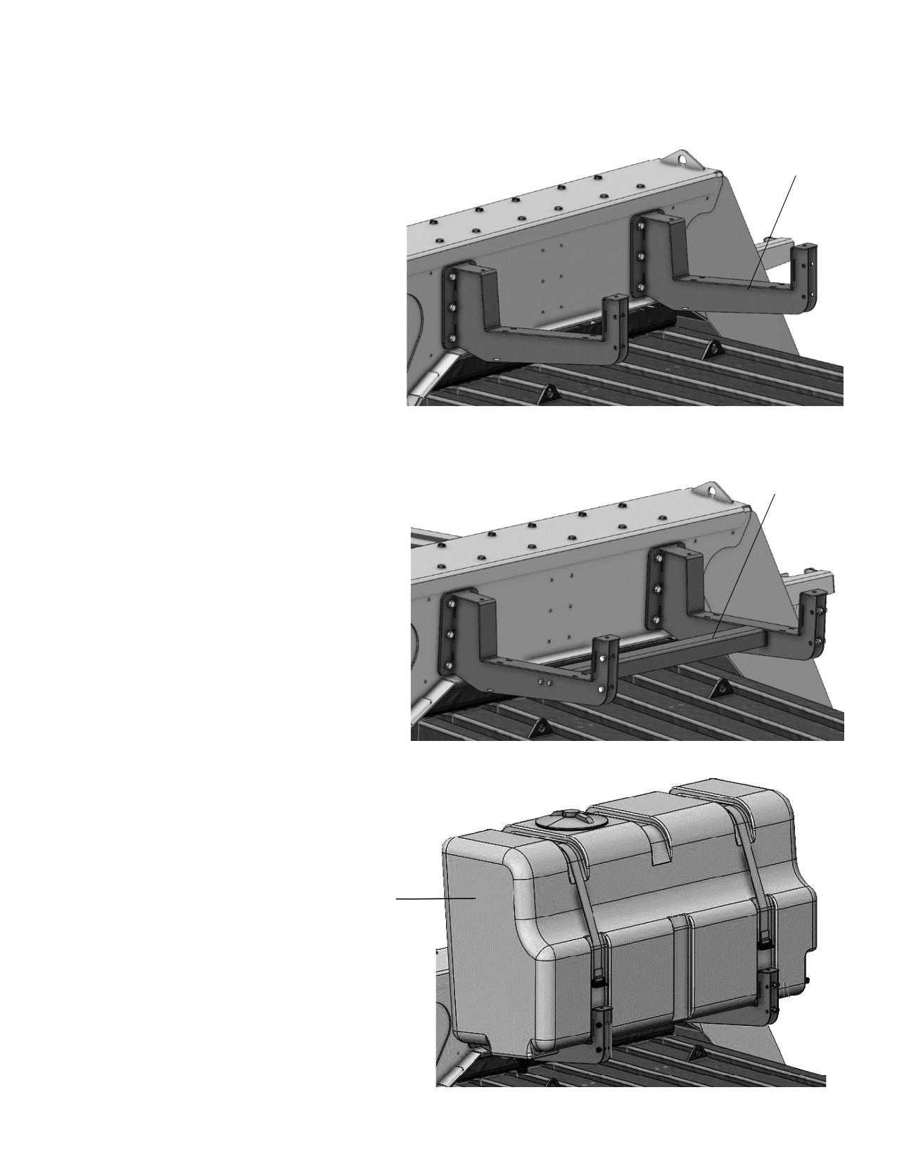
Installation of Applicator
Installation of Tank
1. Install the two saddle legs (001-6707MHD1)
001-6707MHD1
on to the rear of the bale support bracket.
Locate the pre-drilled holes and hardware
from parts bag 20 to mount the legs as
shown (right). Do not fully tighten until cross
beam is installed in next step.
001-6707MHD2
2. Locate the cross beam (001-6707HD2) and
mount between the two tank legs (001-
6707HD1) using the pre-drilled holes on
each leg. Using the hardware in parts bag
20 secure the beam. The tank legs can now
be fully tightened.
3. Position the tank assembly (030-9218) and tank
straps (001-6707P). *Do not tighten tank straps
prior to installing the Rear Light Camera
Bracket in the next step.
001-6707PMZ
5
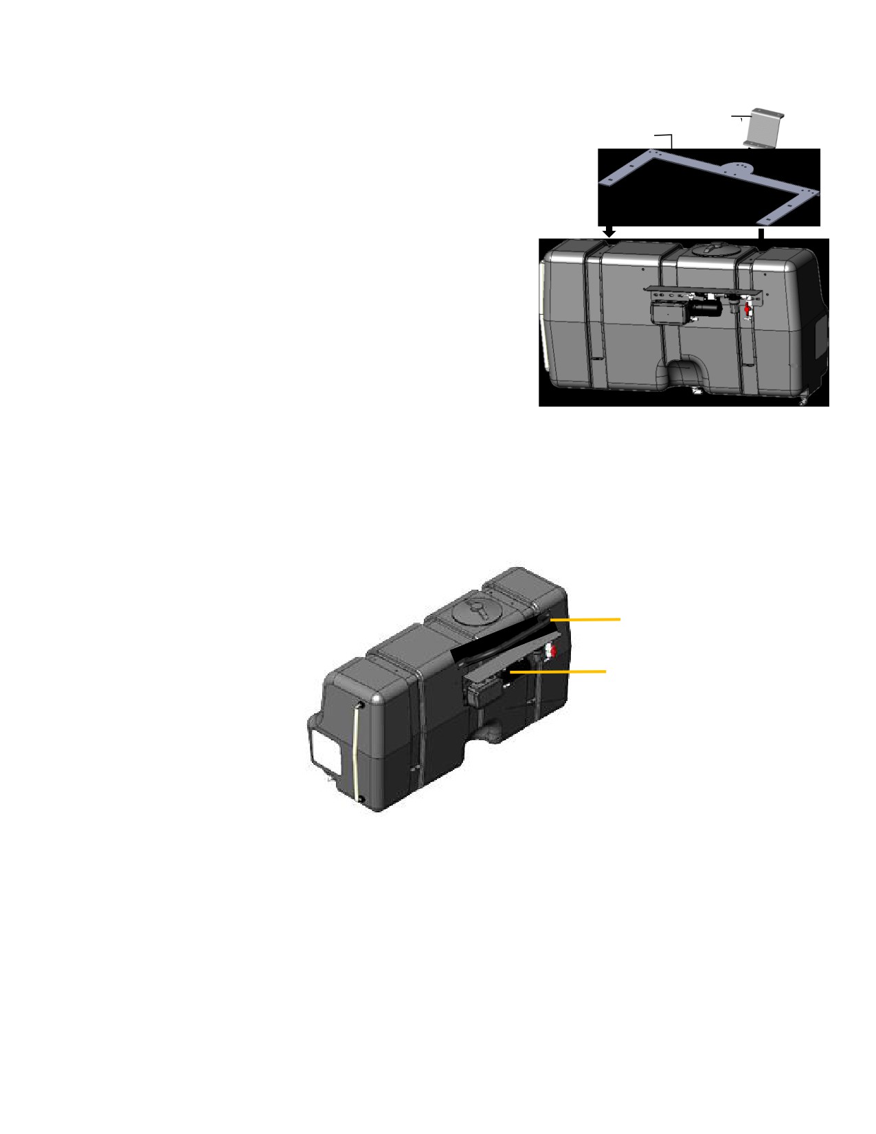
Installation of Tank (continued)
4. Rear Light Camera Brackets Installation
001-6707PMZ
001-6707PM
There is now an optional rear light extension bracket available for the
NH330+ & NH340+ and LB334XL & 434XL baler models. To reposition the
lights, camera, and beacon light to the back of the preservative tank.
Install the camera/light bracket (001-6707PM) as shown on the right by
lining up two holes in the arms of the bracket with the holes on the
tank straps. Using the supplied elevator bolts install the bolt with the
head on the tank side with threads pointing upward.
Install the camera mounting brackets (001-6707PMZ) to the camera
light bracket as shown on right. Move the lights and camera as
needed using the light extension harness
(006-7303LTX).
Note:
The straps will need to be loosened to allow room for placement of the bolts. Retighten after bolts are installed.
Installation of Pump Plate and Hand Rail
Handrail
006-6707HR
Pump Assembly
PMP-7636P
1. Attach handrail (001-6707HR) to tank with two 3/8” x 3/4” flange bolts.
2. Locate pump control (006-7671LS) and attached to pump plate with #10 x 3/4" flat head machine
screws. Choose fittings and install them into valve and pump discharge.
3. Attach pump plate holder (001-4648XB) to tank and just below handrail with two 3/8” x 3/4" flange bolts.
4. Attach pump plate to the pump holder with 3/8” hardware.
5. Connect 1/2" hose between elbow fitting on bottom of tank and valve on pump plate. Secure with
supplied hose clamps.
The Pump Controller and pump heads must be pointing down. Failure to mount the pump plate
assembly in this specified direction will void all warranty of the Pump Controller and pumps
6
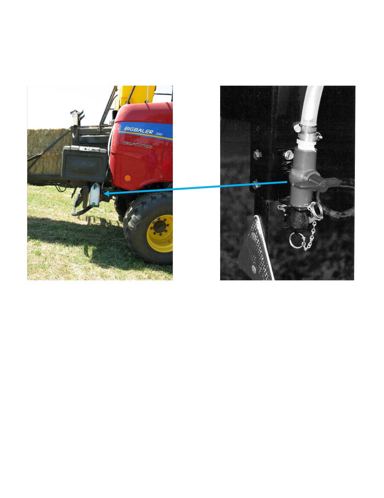
Installation of the Drain & Fill Line
1. Thread 3/4” elbow fitting into end of tank.
2. Run hose from the elbow down the frame to the bottom of the baler.
3. Drill 1/4” (7mm) holes to accept the valve holder bracket and use 5/16” x 1” self-tapping screws.
4. Connect valve assembly to other end of hose. Place hose clamps on both ends.
5. Secure hose to frame using cable locks.
7
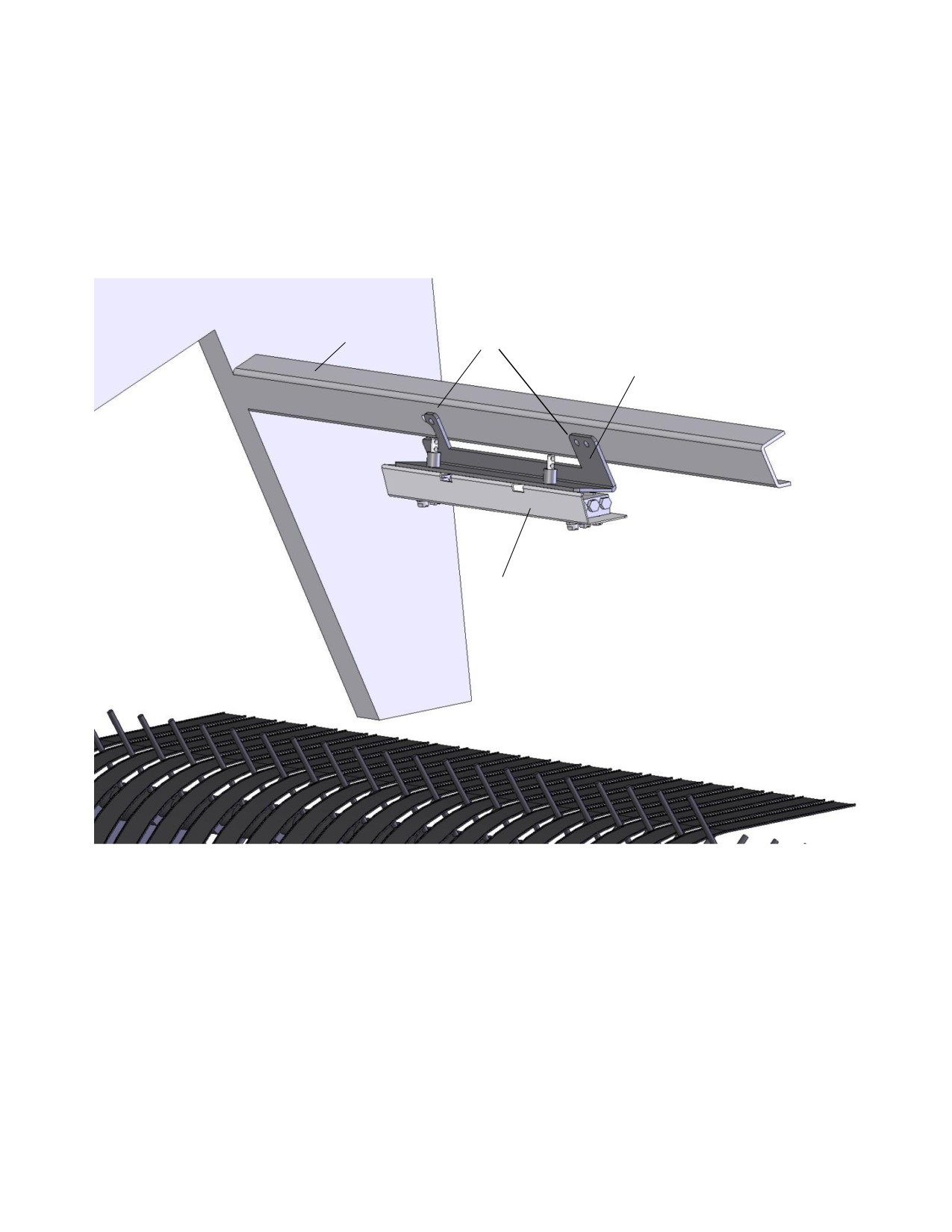
Installation of Install Kit 4636C
1. Locate the baler cross member directly above the rotor (below point A).
2. Locate the four pre-drilled holes on the cross member (point B).
3. Install spray shield holder (001-4435NC) to baler using three 5/16” x 1” bolts, lock washers, hex nuts.
4. Install the spray shield (001-4435NSX) to the the shield holder (001-4435NC) and secure with supplied
lynch pins.
A
B
001-4435NC
001-4435NSX
8
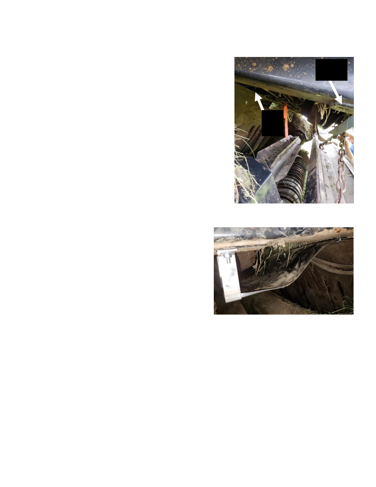
Wind Guard Installation
3x4 Baler
Step 1: Locate the ledge near the spray shield (1) and with 001-
6707MA in hand, mark out drill locations for the two slots of the
2
6707MA bracket. Bracket should be as centered about the spray
shield. If you’re confident with drill locations, drill the two holes and
move to step 2. Also note the factory drilled holes on the tongue of
the baler (2), locate part 001-6707MC and ensure holes align on both
sides.
Step 2: Assemble the wind guard (030-6707WG4). Start by locating
1
all the materials listed above. Using the 1’’x 1/4’’ bolts and washers
place the guard material (001-6707GM4) on the top bracket. Guard
material should now be held in place with only the bolts. Locate part
(001-6707MB) and place over protruding bolts, secure with flat
washers and nuts. Note: Ensure the rubber guard material is placed
on the top side of the of the 6707MA bracket.
Step 3: Again, using the same hardware from step 2 fasten the guard
material to the bottom bracket (001-6707MC) utilizing the remaining
001-6707MB backing bracket to clamp down the material.
Step 4: Bring assembled wind guard to the baler, it is
recommended that you get another person to assist here.
Start by securing the top bracket to the ledge where holes
were previously drilled. Secure with 5/16 x 1’’ hardware. Now
locate the 5/16 x 1.5’’ bolts. Use the bolts, flat washers, and
nuts to secure the bottom bracket to the baler factory drilled
holes. Refer to finished install side view shown on the right.
Note: If installed correctly, the wind guard should not make
contact with the fly wheel or center feed roll when the pick-up
head is fully lifted.
9
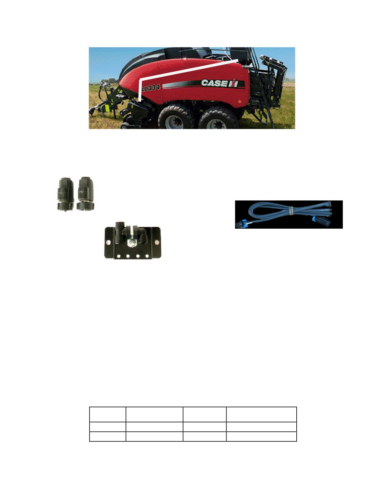
Mounting Solenoids and Hose Routing to Spray Shield
A. Once spray shield is mounted, ensure solenoids 002-2203F are mounted using the solenoid mount plate
001-4648DSH as closely as possible (max distance 3ft) to the spray shield. This will ensure the most precise
application of the preservative.
Solenoids
002-2203F
Solenoid Harness
006-3650-S1
Solenoid Mount
001-4648DSH
B. Once solenoids are mounted, streamline solenoid harness 006-3650-S1 along baler back to connection on
main baler harness 006-765B2. Solenoid with white dot attaches to SOL 1 and Solenoid with blue dot attaches
to SOL 2. Connect harnesses and ensure they are secure.
C. Route hoses along the path or similar inside of the baler, as shown in picture above. Keep hoses away from
moving parts and hydraulic hoses. When all connections are made to the tank, solenoids, and spray shield
secure with existing cable clamps or use cable ties.
D. Connect hoses from spray shield to solenoids. Note: Make sure solenoid with white dot attaches to spray
shield with white dot. Follow same procedure for blue dots.
Tip Connections
Position on 765B2
Dot color
Tip
Hose color
wire
White Dot
8004 or 11004
White
Sol 1
Blue Dot
8008 or 11008
Blue tracer
Sol 2
10
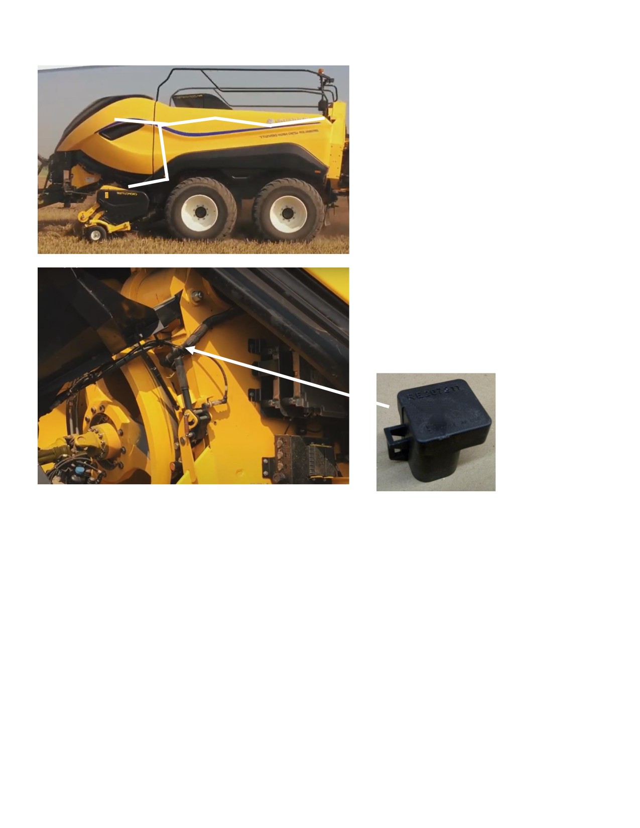
Installation and Routing Wire Harnesses and Baler Interface Harness
Route harnesses along inside of the
baler (left). Keep harnesses away from
moving parts and hydraulic hoses.
Secure with existing cable clamps or use
cable ties. When all connections are
made to the DCP secure wires.
Locate and remove the Active
Terminator of baler (below). Attach Baler
Interface Harness (006-6650VA) to that
location on baler.
Reconnect Active Terminator to open
port of that same harness (006-6650VA)
11
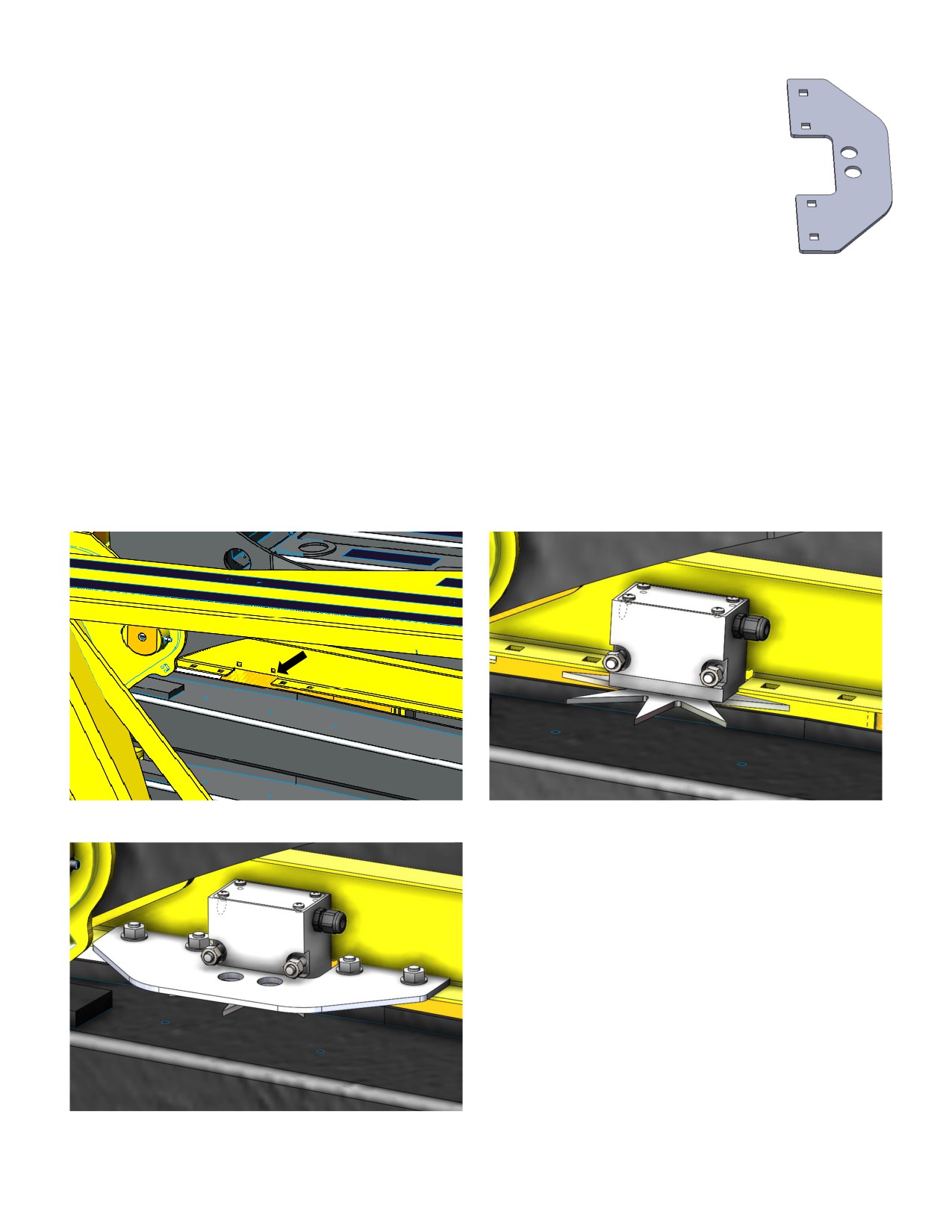
001-4644BBHD
Installation of Star Wheel Moisture Sensors - 700BBHD
1. Locate the two star wheel moisture sensors (030-4642U and 030-4642UE) and star wheel
reinforcement brackets (001-4644BBHD) show on the right and parts bag (E)
2. The two pre-drilled mounting holes for the star wheels are located past the knotters on the
side of the top support bar running the length of the bale chute (Figure 1).
3. Position the star wheel mounting holes and mark the width of the star wheel 4” (112mm).
As well as the depth of the star wheel of 2” (50mm). This piece will need to be removed
from the baler bracket in order for star wheel to fit flush with baler bracket (Figure 2). After
cutting touch up with paint to prevent rusting.
4. Mount star wheel with two position plug on right side of baler when looking at the back. Mount star wheel
with six position plug to left side or ladder side of baler. Use hardware from parts bag (E) to mount
5. Position reinforcement brackets (001-4644BHD) around the star wheel. Shown mounted in Figure 3.
Repeat mounting the star wheel and installation of the reinforcement bracket on the right side of baler.
Used suppled 3/8” x 3/4” Carriage bolts and flange nuts to secure
6. Attach harness (006-7307EM2) wires to star wheels and route to (IPM) module and connect to the square
plug on it.
Figure 1
Figure 2
Figure 3
12
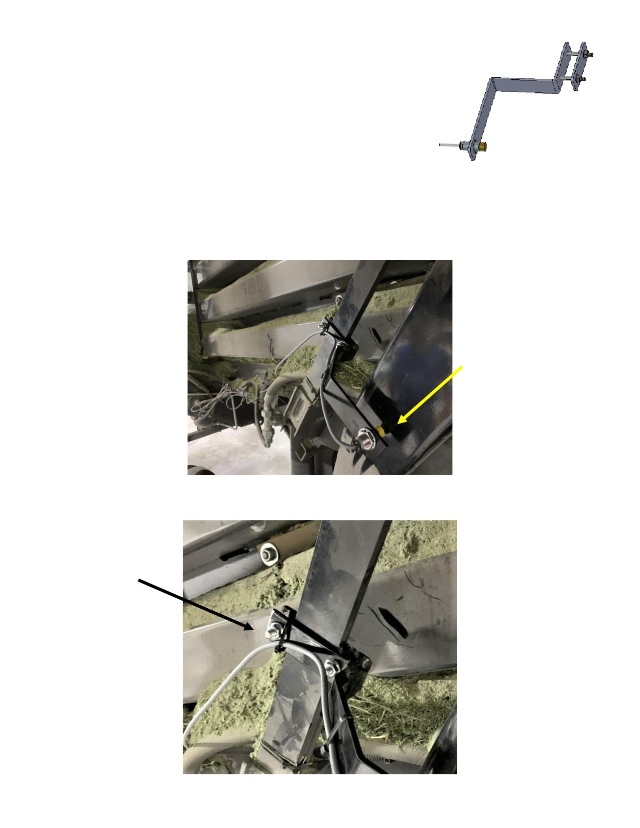
Installation of End of Bale Sensor
The end of bale sensor determines the position of the needles on the baler.
When the needles cycle the sensor communicates this information to the
ISO Communication Module (ICM). This information is used for job records
and will be used by the optional Bale Identification system.
Mount the end of bale sensor bracket (001-4648NA and 001-4648NB) as shown on the back right of the baler
(opposite of the ladder). This bracket will clamp to the diagonal support using the backing plate and supplied
hardware (5/16” x 1 ½” hex bolt with flat washer, lock washer, and nut). There is no exact placement, the
sensor just needs to see the needle arm when in the home position. Adjust sensor in or out so that it is about
ó” away from the needle arm and tighten both nuts. Be sure it is not making contact, causing damage, or not
too far away from the needle arm, preventing it from reading.
Run the sensor cable (006-7401) and extension (006-7401BBEXT) up to main harness (006-765B2) and
attach to EOB plug.
13
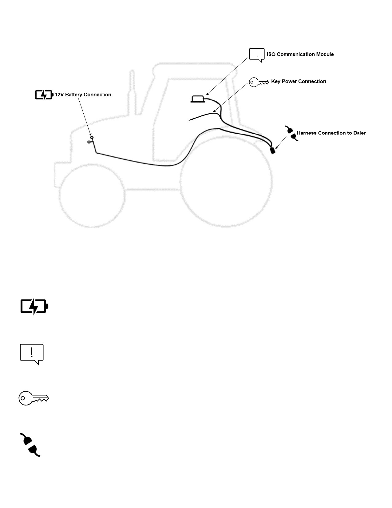
Tractor Setup
The general tractor setup of the 700 Series applicator can be seen above. The main harness of interest is the
tractor power/communication harness (006-765IC). This harness will connect at the tractor battery, to the ISO
Communication Module (ICM) mounted in the cab, a keyed power connection point, and connect at the hitch
area to the baler power/communication harness (006-765B2). View below to see highlighted installation
instruction:
The 12V battery connection must be at the tractor battery. Connection to
12V Battery Connection
alternative locations such as an accessory port can cause problems with
applicator system.
*MUST BE CONNECTED DIRECT TO TRACTOR BATTERY TERMINALS*
The ISO communication module is to be mounted inside the cab. Other
ISO Communication Module
mounting locations can lead to issues with weathering and operation.
Once installed and the system is powered, a green light will turn on with
the ICM module.
Ensure a solid keyed connection is found inside the cab and wired into.
Key Power Connection
Poor keyed power connection can result in applicator system issues.
The tractor harness connects at the hitch to baler power/communication
Harness Connection to Baler harness (006-765B2). This will allow the system components to
communicate with one another. Ensure connections are debris and
corrosion free.
14
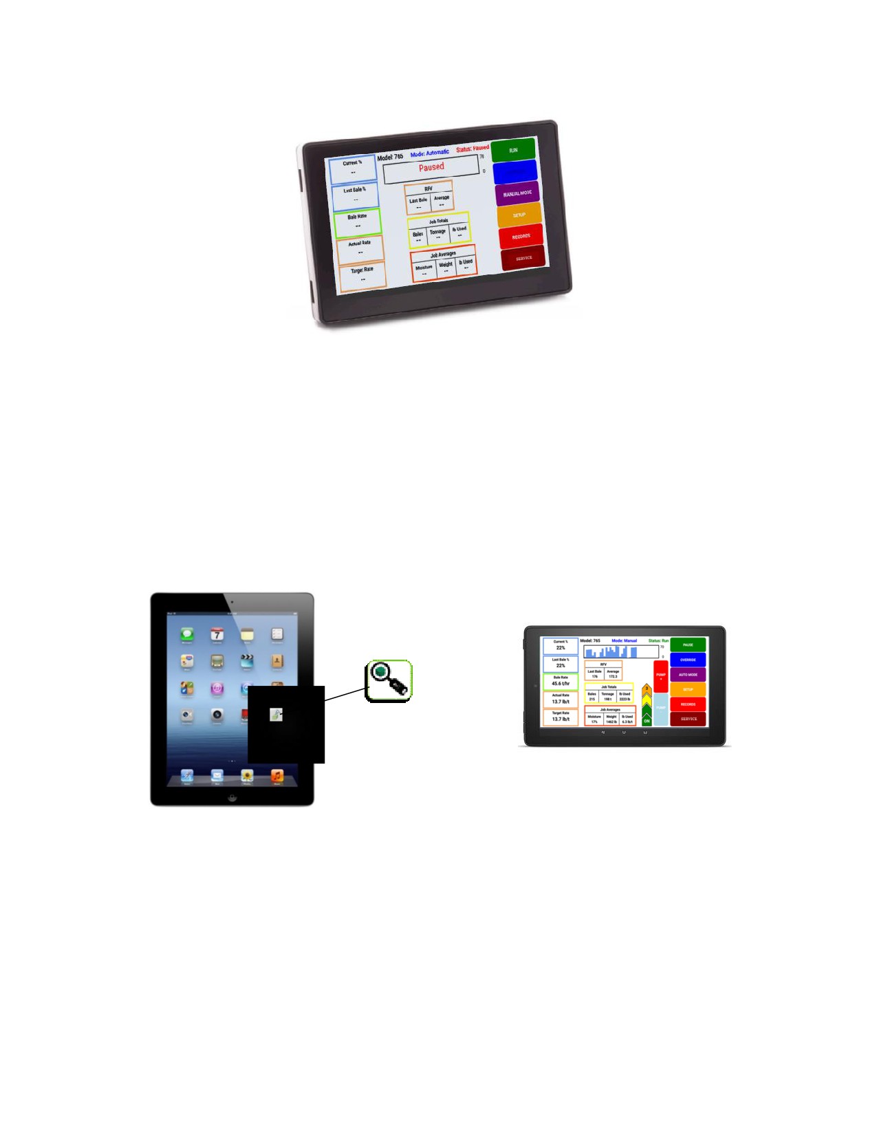
Display Options
Optional Harvest Tec Display
The 700 series Harvest Tec Display will allow you to set your real time baling parameters to ensure the most
precise application to every bale. This is done by utilizing the improved touch technology to select objects,
enter data, and swipe through operational screens.
The Harvest Tec Display offers easy integration by connecting to the additional CAN plug on the 006-765IC
harness. Once, connected the Harvest Tec display will power up with applicator system.
Note: The Harvest Tec Display must be used as a standalone display, the baler cannot run both
integrated and on the Harvest Tec Display. Must be one or the other. Removal of the 006-765VA or
integration harness is required when equipped.
Optional Tablet Display
Precision Baling App
The iOS or Android Tablet displays offer the ability to communicate with the 700 series applicator system via
hard-wired connection to the ISO Communication Module (ICM). Through the free Precision Baling App, the
operator can set real time baling parameters to ensure the most precise application to every bale. This
provides a multi-use option while utilizing the improved app to select objects, enter data, and easily switch
through operational screens. The Tablet Display offers easy integration by connecting a charging cable to the
USB port on the ICM module. Once connected the Harvest Tec applicator will display upon opening the app
and powering up the applicator system. Tablets can be used in addition to integrated baler VT display.
*Made for iPad® (3rd generation minimum) or Android Tablet (Does not work with Amazon Fire).
Required to be running the most current operating system or one version previous.
*iPad is a trademark of Apple Inc., registered in the U.S. and other countries.
15
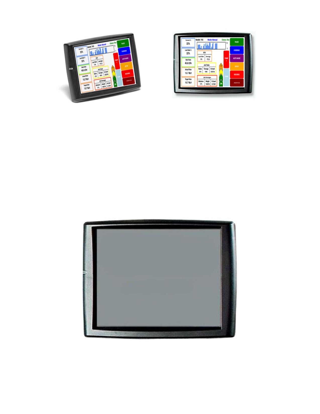
Optional Baler VT Integration
The 700 series integration to the Baler VT allows for the ability to set your real time baling though the baler
VT and monitor both baler settings and Harvest Tec system parameters on one screen to ensure the most
precise application to every bale.
The 700 series offers easy integration by connecting to the additional CAN plug on the 006-765B2 harness.
Once connected the Harvest Tec system will display with power up of the baler and applicator system.
Baler Display Integration
The ISOBUS Monitor utilizes touch screen options to make selections. Selections are made by finding the
desired selection and pressing the touch screen icon. All buttons are labeled and color coded.
16
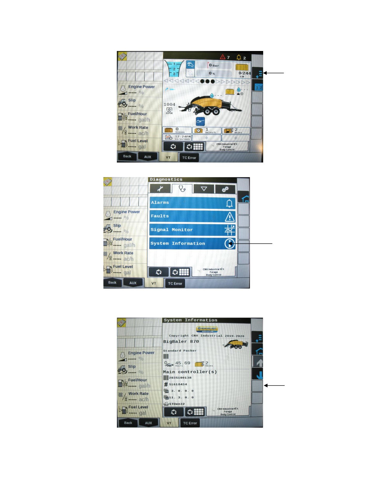
Follow the steps below to setup the integration of the 700 Series into the Pro 1200 Series Monitor.
1. Select the baler Setup tab in the top right corner of the baler run screen.
2. Open the Diagnostics tab by pressing the (stethoscope icon) and select the System Information tab.
3. On the System Information page press and hold the first blank square box under the down arrow on the right side of
the screen for 10 Seconds.
17
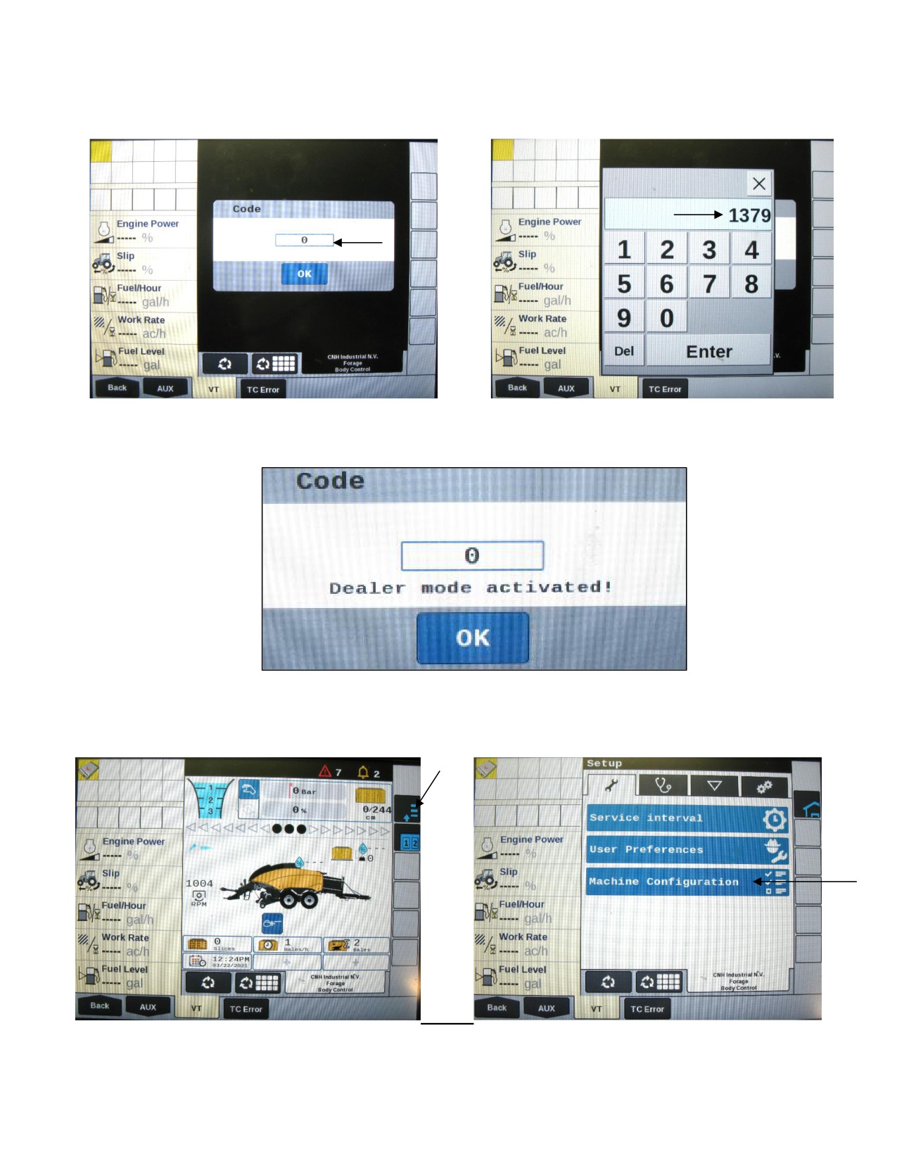
700BBHD Integration Instructions (continued)
4. After 10 seconds the first screen below will appear prompting you for a code. Press the ‘0’ and enter the Code 1379
when the numbers appear.
The screen below will appear alerting you ‘Dealer Mode Activated’. Press OK and go back to the balers home
screen.
5. Select the baler Setup tab in the top right corner of the baler run screen. Then press Machine Configuration from the
baler setup page (wench icon at top).
18
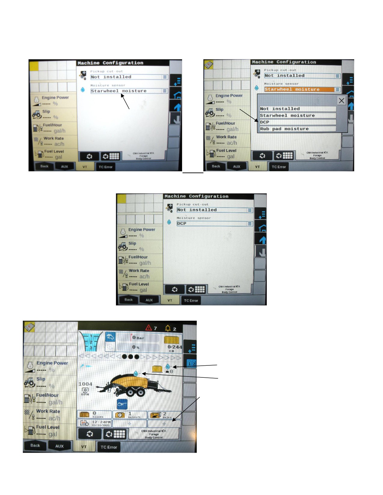
700BBHD Integration Instructions (continued)
6. Select the Moisture Sensor line on the Machine Configuration screen. On the next screen that appears select DCP
from the drop down
The moisture sensor selection will now read DCP on the Machine Configuration page.
The current bale moisture content will now display above
the baler next to the water droplet and the previous bale
moisture will display next to the bale in above the are
above the bale chute (below).
Previous Bale Moisture
Current Bale Moisture
Use the (+) signs to add any other Harvest Tec Options
that you would like to have show on your baler run
screen.
Refer to the operation manual for the
700 Series Large Square Baler
Models to view the operation details.
19
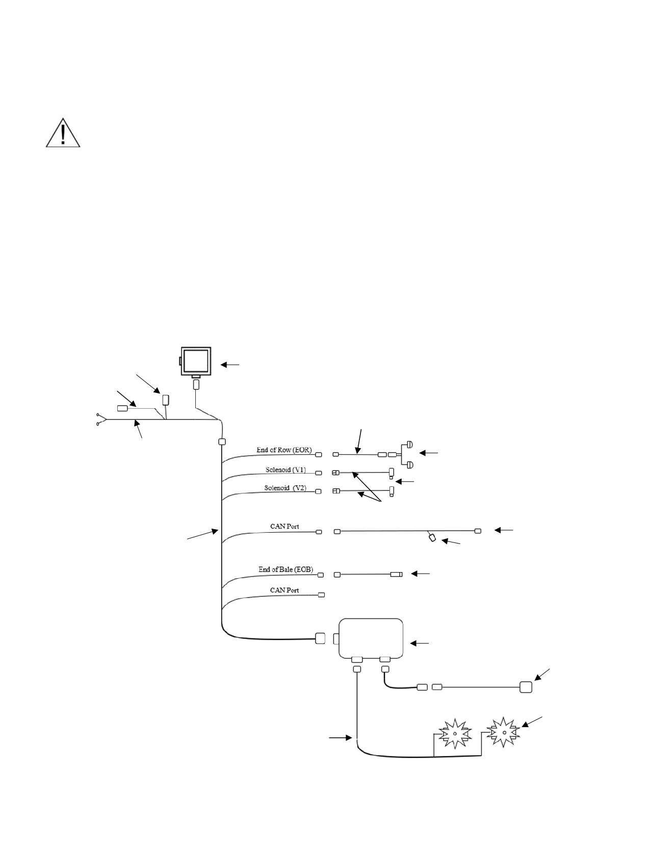
Wiring Diagram - 700 Series
1. Connect the power harness (006-765IC) to the tractor battery (12 volt) using the red wire with fuse to the positive
side and the black wire to the negative.
A. The power harness must be connected to the battery!
CONTACT HARVEST TEC BEFORE MODIFICATIONS.
*The unit will draw more amps than convenience outlets can handle. Any modifications of the power
harness will void systems warranty*
B. This unit will not function on positive ground tractors.
C. If the unit loses power while operating it will not keep track of accumulated pounds of product
used.
2. The power harness on the tractor (006-765IC) will run from the tractor battery to the hitch. The power harness on
the baler (006-765B2) will connect to the tractor power harness (006-765IC) at the hitch.
3. Connect the keyed power wire (006-765CPH) to a keyed power source on the tractor.
The keyed power wire must connect to a keyed source or the unit will not power up correctly.
4. Attached the ISO Communication Module (006-7671) to the tractor power harness (006-765IC).
5. Attach the End of Bale (EOB) connection on baler harness (006-765B2) to the EOB Sensor (006-7400).
6. Attach the Flowmeter (006-4724A) to ISO Pump Module connection on pump plate assembly.
7. Attach the rubber molded connector on pump plate to the Pump (007-4120DE).
8. Attach star wheel (030-4642 U/UE) connection to ISO Pump Module on pump plate assembly.
System Wiring Diagram
Optional Harvest Tec
ISO Communication Module (ICM)
Display Harness
030-6673
006-765GH
Key Power Harness
006-765CPH
Optional
Hay Indicator Harness
006-7503H
Power Harness on Tractor
Hay Indicators
006-765IC
006-7502(E / R)
Solenoids
002-2203F
Solenoid Harness
006-3650-S1
Baler Integration Harness
006-765VA
Power Harness on Tractor
Active Terminator from Baler
006-765B2
End of Bale Sensor
006-7400
700 ISO Pump Module
006-7671LS
Flow Meter
006-4724A
Star Wheels
Moisture Harness
030-4642 (U/UE)
006-7303EM2
20
Pin Outs
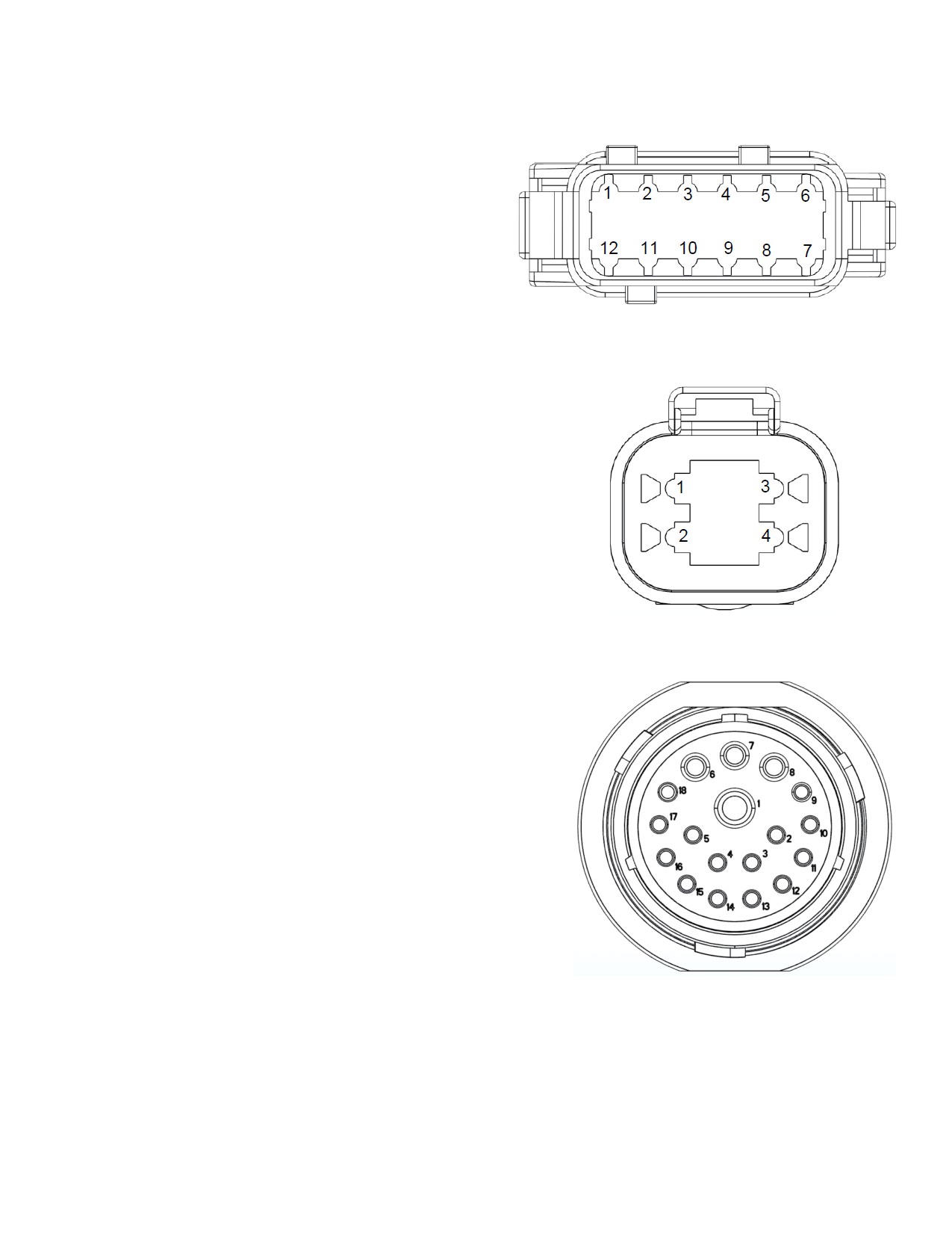
Integrated Control Module (ICM) on harness 006-765IC
(Deutsch Plug Number: DTM06-12SA)
Pin 1
Red
+12V from ECU
Pin 2
Purple
Signal Wire
Pin 3
Red/White
+12V CAN X
Pin 4
Black/White
Ground CAN X
Pin 5
Orange
CAN X Hi
Pin 6
Blue
CAN X Lo
Pin 7
Green
ISO CAN Lo
Pin 8
Yellow
ISO CAN Hi
Pin 9
White
GPS Extension 1
Pin 10
Gray
GPS Extension 2
Pin 11
Brown
GPS Extension 3
Pin 12
Black
Ground from ECU
ISOBUS Plug on harness 006-765IC
(Deutsch Plug Number: DT04-4P)
Pin 1
Red
+12V from ECU
Pin 2
Yellow
ISO CAN Hi
Pin 3
Green
ISO CAN Lo
Pin 4
Black
Ground from ECU
Power / Communication Harness 006-765IC at Baler Hitch
(Deutsch Plug Number: HDP24-24-18PN)
Pin 1
Not Used
----
Pin 2
Yellow
ISO CAN Hi
Pin 3
Green
ISO CAN Lo
Pin 4
Red
+12V Power to ECU
Pin 5
Black
Ground to ECU
Pin 6
Red
+12V From Battery
Pin 7
Not Used
----
Pin 8
Black
Ground From Battery
Pin 9
Not Used
----
Pin 10
Purple
Signal Wire
Pin 11
Red/White
+12V CAN X
Pin 12
Black/White
Ground CAN X
Pin 13
Orange
CAN X Hi
Pin 14
Blue
CAN X Lo
Pin 15
White
GPS Extension 1
Pin 16
Gray
GPS Extension 2
Pin 17
Brown
GPS Extension 3
Pin 18
Not Used
----
21
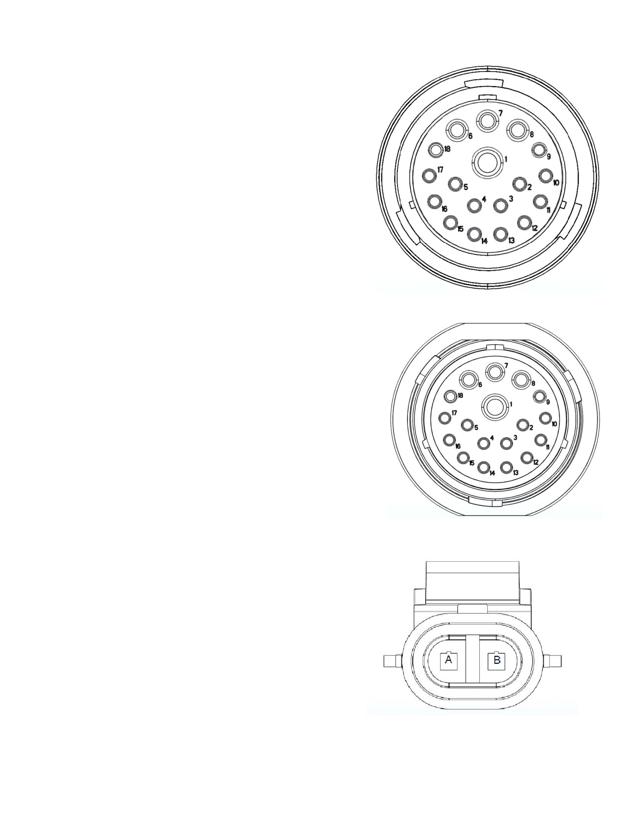
Power / Communication Harness 006-765B2 at Baler Hitch IPM
(Deutsch Plug Number: HDP26-24-18SN)
Pin 1
Not Used
----
Pin 2
Yellow
ISO CAN Hi
Pin 3
Green
ISO CAN Lo
Pin 4
Red
+12V Power to ECU
Pin 5
Black
Ground to ECU
Pin 6
Red
+12V From Battery
Pin 7
Not Used
----
Pin 8
Black
Ground From Battery
Pin 9
Not Used
----
Pin 10
Orange/White
+12V Power to EOR
Pin 11
Not Used
----
Pin 12
Not Used
----
Pin 13
Not Used
----
Pin 14
Not Used
----
Pin 15
Not Used
----
Pin 16
Not Used
----
Pin 17
Not Used
----
Pin 18
Not Used
----
Power / Communication Harness 006-765B2 at IPM Module
(Deutsch Plug Number: HDP24-24-18SN)
Pin 1
Not Used
----
Pin 2
Yellow
ISO CAN Hi
Pin 3
Green
ISO CAN Lo
Pin 4
Red
+12V Power to ECU
Pin 5
Black
Ground to ECU
Pin 6
Red
+12V From Battery
Pin 7
Not Used
----
Pin 8
Black
Ground From Battery
Pin 9
Not Used
----
Pin 10
Orange/White
+12V Power to EOR
Pin 11
Orange/Black
Ground to EOR
Pin 12
Purple/Green
EOR Signal
Pin 13
Blue/White
EOB Signal
Pin 14
Gray/Red
+12V Power to Solenoid 1
Pin 15
White/Black
Ground to Solenoid 1
Pin 16
Orange/Red
+12V Power to Solenoid 2
Pin 17
White/Black
Ground to Solenoid 2
Pin 18
Not Used
----
Solenoid 1 Plug on Baler Harness 006-765B2
(Deutsch Plug Number: APTIV 12052641)
Pin B
Gray/Red
+12V to Solenoid 1
Pin A
White/Black
Ground to Solenoid 1
Solenoid 2 Plug on Baler Harness 006-765B2
(Deutsch Plug Number: APTIV 12052641)
Pin B
Orange/Red
+12V to Solenoid 2
Pin A
White/Black
Ground to Solenoid 2
22
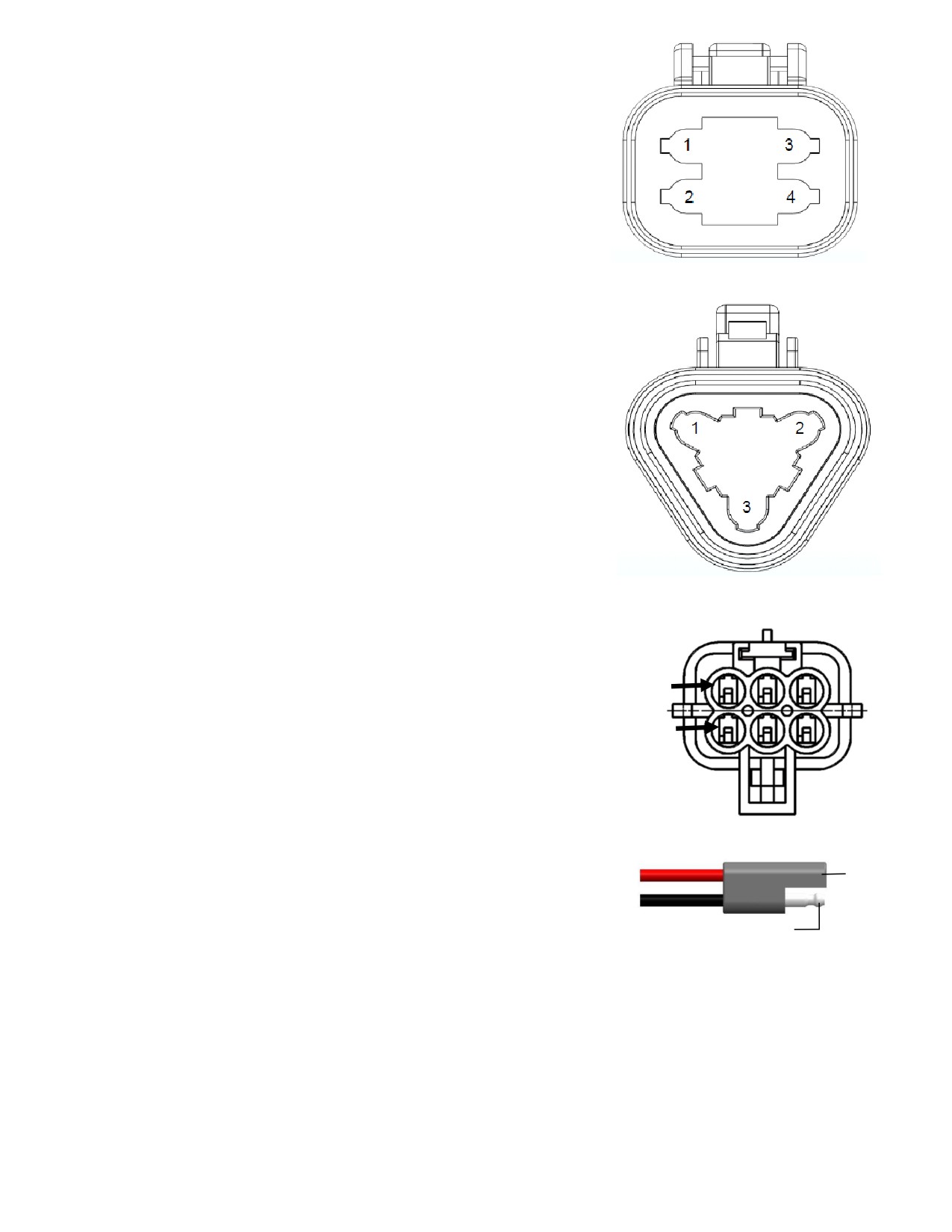
CAN / IDM on Baler Harness 006-765B2
(Deutsch Plug Number: DT06-4S)
Pin 1
Red
+12V to ECU
Pin 2
Yellow
ISO CAN Hi
Pin 3
Green
ISO CAN Lo
Pin 4
Black
Ground to ECU
End of Bale Sensor Plug on Baler Harness 006-765B2
(Deutsch Plug Number: DT06-3S)
Pin 1
Orange/White
+12V to End of Bale Sensors
Pin 2
Orange/Black
Ground to End of Bale Sensors
Pin 3
Blue/White
Signal
End of Row Sensors Plug on Baler Harness 006-765B2
(Deutsch Plug Number: DT06-3S)
Pin 1
Orange/White
+12V to End of Bale Sensors
Pin 2
Orange/Black
Ground to End of Bale Sensors
Pin 3
Blue/White
Signal
Integration Harness Plug on Baler Harness 006-765VA
(Plug: APTIV 12052848)
Pin A
Not Used
----
A
Pin B
Red
TBC Power
Pin C
Not Used
----
D
Pin D
Gray
TBC Ground
Pin E
Orange
CAN Hi
Pin F
Blue
CAN Lo
Pump Connection on 700 Controller Harness
Pin 1
(16 AWG Two-Wire Plug)
Pin 1 Red
Power to Pump
Pin 2 Black
Ground to Pump
Pin 2
23
Parts Breakdown
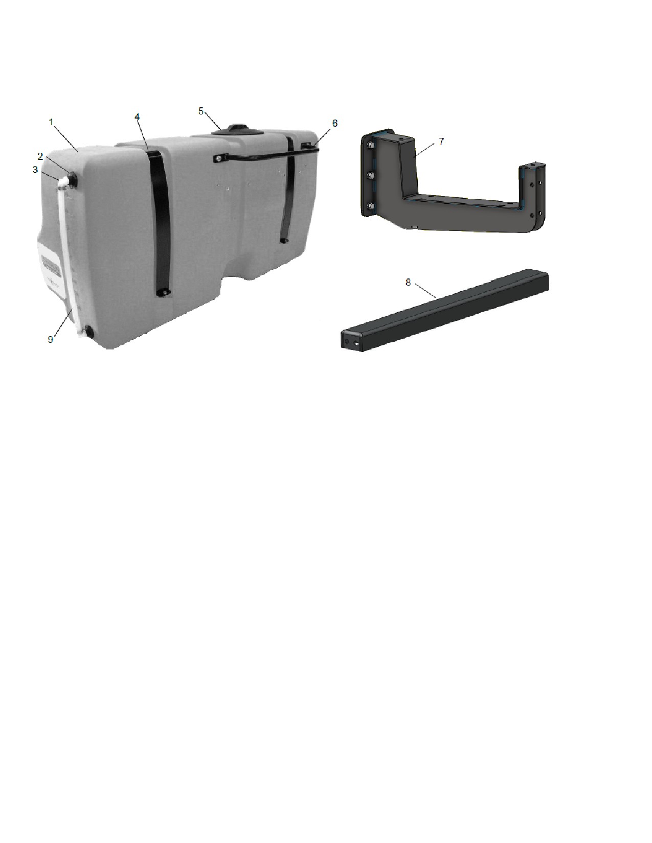
Tank and Saddle Legs
Ref Description
Part Number Qty
Ref Description
Part Number
Qty
1
Tank
005-9218
1
7 Tank Leg Mount
001-6707MHD1
2
2
1/2" tank fitting
005-9104
2
8 Cross Beam
001-6707MHD2
1
3
Elbow
003-EL1212
2
9
1/2" hose
002-9001
2
4
Tank straps
001-6707P
2
NP Elbow
003-EL3434
1
5
Tank lid
005-9022H
1
NP Elbow
003-EL3412
1
6
Handrail
001-6707HR
1
NP
3/4” tank fitting
005-9100
2
24
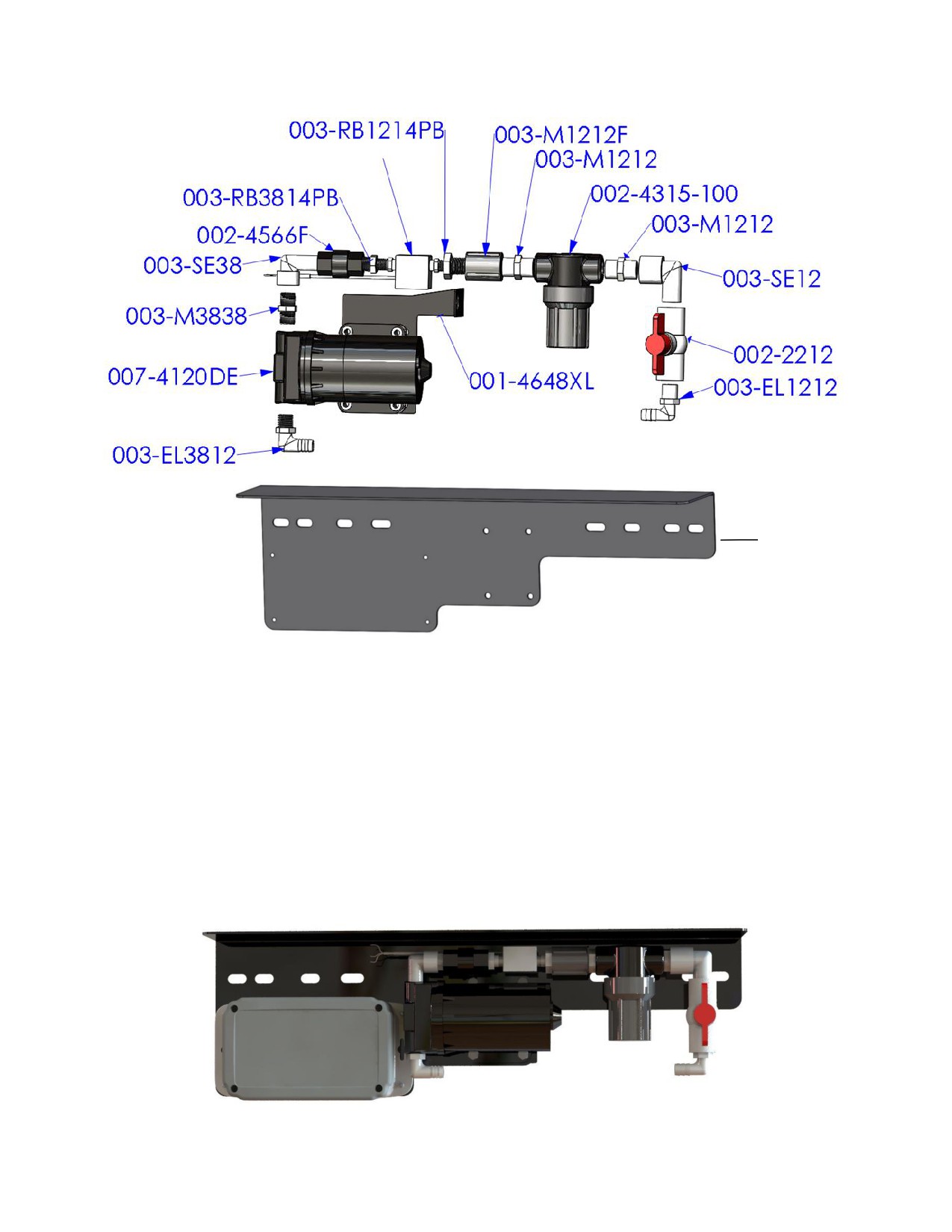
Parts Breakdown for Pump Assembly
006-4724A
001-4648X
Part#
Description
Qty
Part#
Description
Qty
003-EL3812
3/8” MPT X 1/2"HB Elbow
1
003-M1212
1/2" Union
2
007-4120DE
300 Series Pump
1
002-4315-100
1/2" Line Strainer-100 Mesh
1
003-M3838
3/8” x 3/8” Union
1
003-SE12
1/2" Street Elbow
1
003-SE38
3/8” Street Elbow
1
002-2212
1/2" Ball Valve
1
002-4566F
3/8” Check Valve
1
003-EL1212
1/2"MPT x 1/2"HB
1
003-RB3814PB
RB 3/8” x 1/4” Reducer
1
001-4648XL
300 Pump Support
1
006-4728R
Flow Meter - Block Style
1
001-4648X
Pump Plate Mount
1
003-RB1214PB
RB 1/2" x 1/4" Reducer
1
003-A1212
Not Pictured
1
003-M1212F
1/2" Coupler
1
003-A3812
Not Pictured
1
Completed Assembly
*Note: Due to alternative baler designs, elbow 003-EL3812 can be replaced by straight fitting 003-A3812. As
well as elbow 003-EL1212 can be replaced by straight fitting 003-A1212. Both straight fittings are included.
25
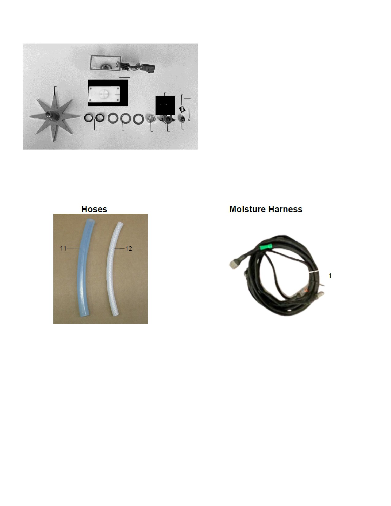
Star Wheel Sensors
Ref
Description
Part#
Qty
1
Block Cover
006-4642UC
1
2
Star Wheel Block
006-4642UB
1
10
3
Star Wheel Gasket
006-4642UG
1
2
4
Electric Swivel
006-4642A
1
5
Swivel Insert
006-4642B
1
9
7
6
Encoder
006-4512E
1
1
5
7
Encoder Mount
006-4512P
1
2
8
Washers
006-4642K
1
9
Star Wheel
006-4641C
1
10
Encoder Harness (6 pin)
006-7307EM
1
3
8
4
NP
Moisture Harness (2 pin)
006-7307M
1
2
6
NP
Star Wheel Reinforcement
001-4644BB
2
1-10
Star wheel assembly
030-4642UE
1
(w/ Encoder)
1-5
Star wheel assembly
030-4642U
1
(w/o Encoder)
Ref Description
Part #
Qty
Ref Description
Part #
Qty
1/2” Hose
1
Moisture Harness
006-7307EM2
1
11
002-9001
30ft
(Tank to Solenoid)
1/4" Hose
12
002-9016
6ft
(Solenoid to Tips)
26
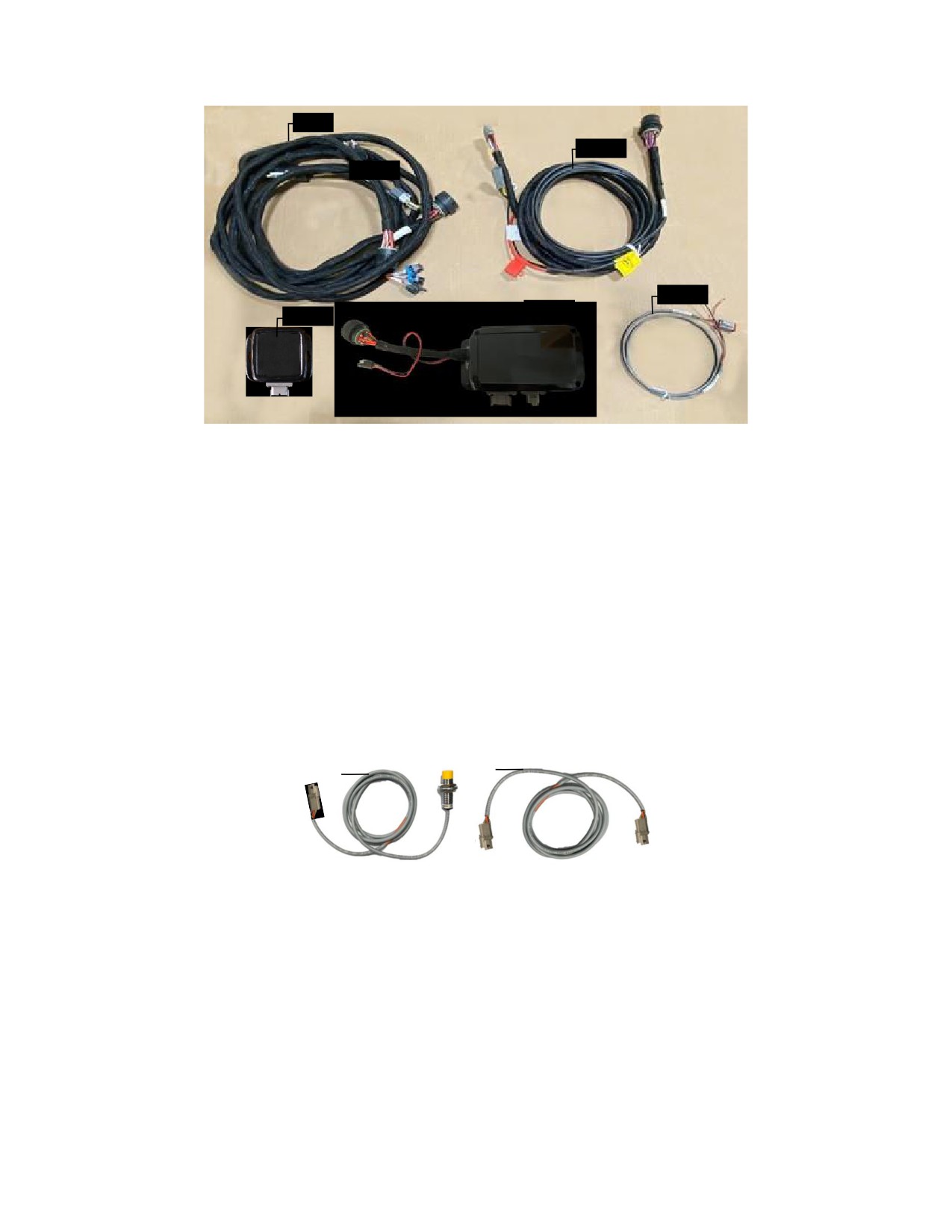
Control Box and Wiring Harnesses
1
2
2
3
5
Ref Description
Part#
Qty
Ref Description
Part#
Qty
1
Power Lead Baler 20’
006-765B2
1
NP Baler Integration Harness
006-765VA
1
2
Power lead tractor
006-765IC
1
NP Dust Plug Kit
006-765DP
1
3
Key Switch Wire
006-765CPH
1
4
ISO Pump Module
006-7671LS
1
5
ISO Communication
006-6673
1
Module
End of Bale Sensor Kit
2
1
27
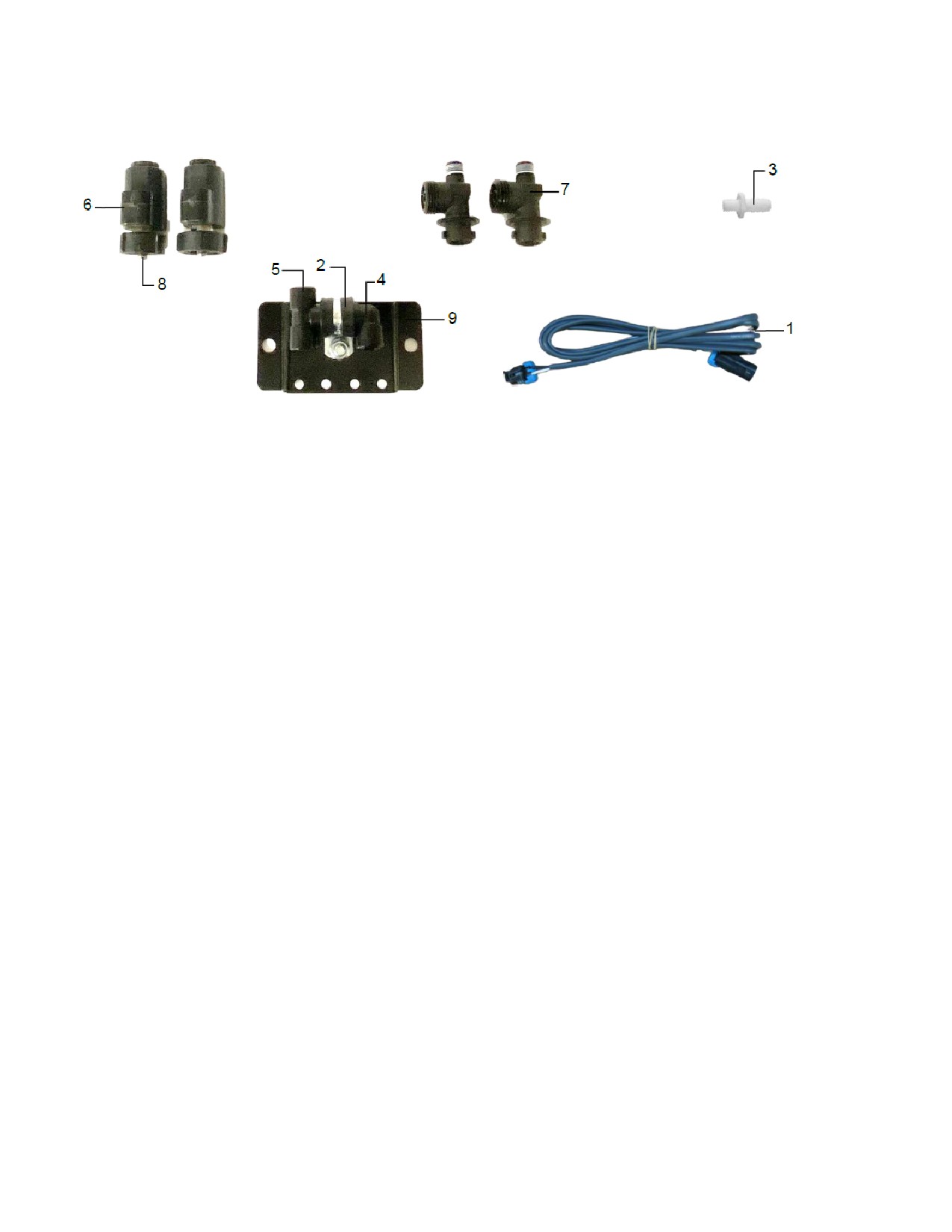
700 Solenoid Package
Solenoid Package
Ref Description
Part #
Qty Ref Description
Part #
Qty
1
Solenoid Harness (5’)
006-3650-S1
2
6
Solenoid
002-2203F
2
2
Hose Clamp #6
003-9003
1
7
Solenoid Check Valve
004-1207VF
2
3
1/4" x 1/2" Straight Fitting
003-A1412
1
8
1/4" Nipple
003-M14
2
4
1/4" Elbow
003-SE14F
1
9
Solenoid Holder
001-4648DSH
1
5
1/4” Tee Fitting
003-TT14SQ
1
NP O-Ring Kit
002-2203FG
2
Complete Assembly
SOL-3SP-LSB
28
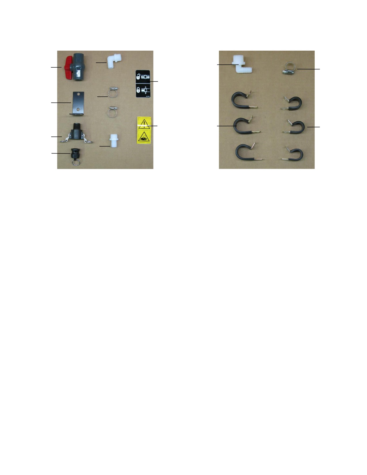
Hose and Drain/Fill Line
PBA-1
PBP-16
5
10
1
12
8
6
2
9
11
13
3
7
4
Ref Description
Part #
Qty
Ref Description
Part #
Qty
1
3/4" Ball Valve
002-2200
1
8
Valve Decal
DCL-8004
1
2
Valve Holder
001-6702H
1
9
Hazard Decal
DCL-8001
1
3
Female Coupler
002-2204A
1
10
3/4" x 1/2" Elbow
003-EL3412
1
4
Male Shut-Off Plug
002-2205G
1
11
3/4" Jiffy Clip
008-9010
3
5
3/4” x 3/4" Elbow
003-EL3434
1
12
#6 Hose Clamp
003-9003
1
6
#10 Hose Clamp
003-9004
2
13
Small Jiffy Clip
008-9009
3
7
3/4" x 3/4" Straight Fitting
003-A3434
1
10
3/4" x 1/2" Elbow
003-EL3412
1
Complete Drain Fill Kit
030-0493DFK
29
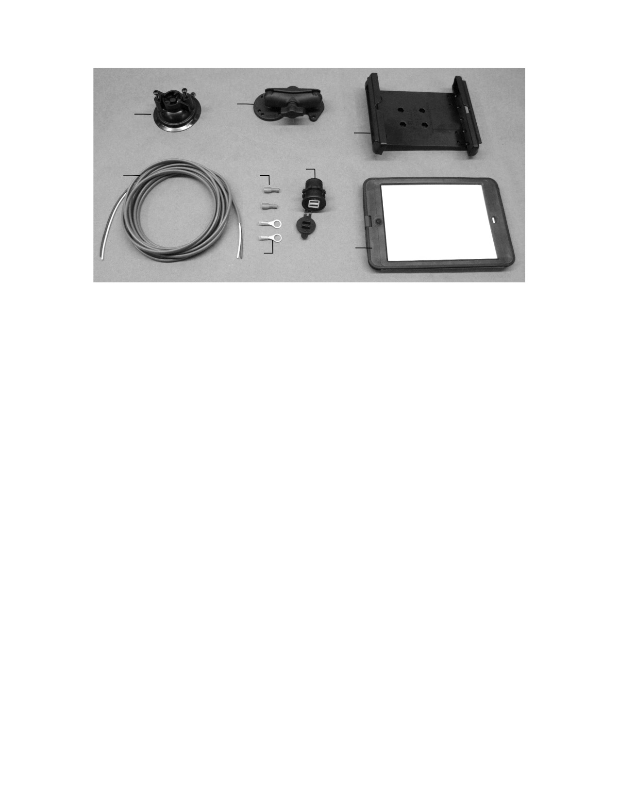
Optional iPad Mini Mounting Kit (030-2014MK)
2
1
3
7
4
5
8
6
Ref Description
Part #
Qty
1
Suction cup mount
001-2012SCM
1
2
Ram mount
001-2012H
1
3
iPad Mini® spring load cradle (Mini 4)
001-2012SLC
1
4
16-gauge power wire
006-4723P
1
5
Female spade connector
Hardware
2
6
Eye loop connector
Hardware
2
7
iPad Mini Charger 12V
001-2012P
1
8
iPad Mini 4 case
001-2012C4
1
NP
4-amp fuse
Hardware
1
Mounting Kit Assembly
030-2014MK
(Includes All Parts)
Installation Instructions
1. Identify 12V power source for wires to connect.
a. Eye loops included if wiring directly to the battery is desired.
b. Test for key power source if preferred to have power to the USB shut off with the key.
2. Once power source is identified, cut wires to desired length.
3. Crimp the two supplied quick connectors onto each the white and black wire.
4. Remove the round locking plastic nut from USB plug before connecting the wires. Black (+) White (-).
5. The wires will then be hooked to the designated terminals on the bottom of the USB plug
6. Drill a 1 1/8” hole in the preferred mounting location. Be sure to clean any sharp edges after drilling.
7. Feed the wires through the mounting hole.
8. If using the round plastic nut to secure plug in place, slide the nut back over the wiring before
connecting the wires to powered source.
9. Connect the wires to the identified power source if easier to do so before tightening the plug into place.
10. Tighten plug using either the round plastic nut or mounting plate and two screws, both options supplied.
11. Once connected, hook a USB charging cord into the plug and connect a mobile device/tablet to ensure
the plug is operating as you wish (key power working properly if necessary).
*iPad mini is a trademark of Apple Inc., registered in the U.S. and other countries.
30
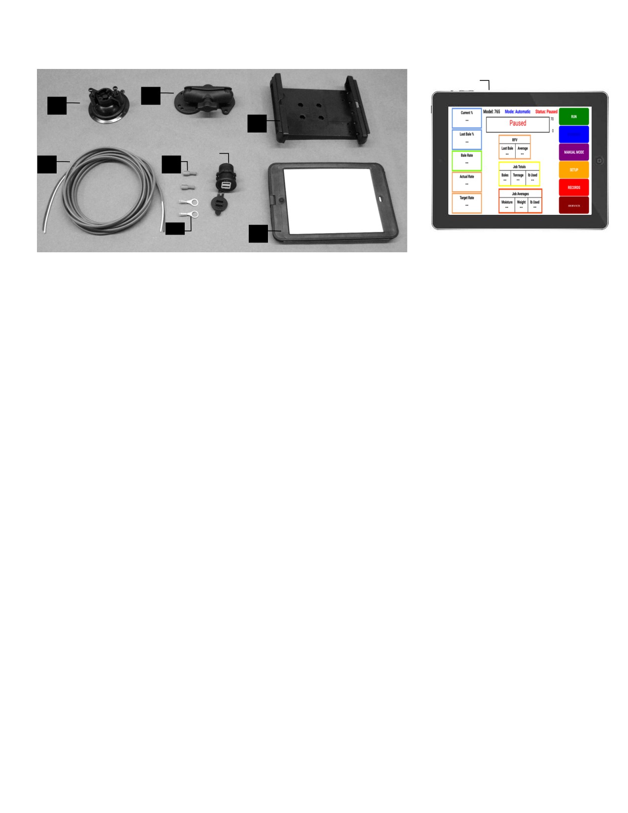
Optional iPad Display Kit (030-4670DK)
9
2
1
3
7
4
5
6
8
Ref Description
Part #
Qty
1
Suction Cup Mount
001-2012SCM
1
2
Ram Mount
001-2012H
1
3
iPad Mini® Spring Load Cradle (Mini 2)
001-2012SLC
1
4
16 Gauge Power Wire
006-4723P
1
5
Female Spade Connector
Hardware
2
6
Eye Loop Connector
Hardware
2
7
iPad Mini Charger 12V
001-2012P
1
8
iPad Mini 4 case
001-2012C4
1
9
iPad Mini 4
006-2670IP
1
NP
4 Amp Fuse
Hardware
1
Mounting Kit Assembly
030-2014MK
(Includes All Parts)
Installation Instructions
a. Identify 12V power source for wires to connect.
b. Eye loops included if wiring directly to the battery is desired.
c. Test for key power source if preferred to have power to the USB shut off with the key.
d. Once power source is identified, cut wires to desired length.
e. Crimp the two supplied quick connectors onto the white and black wire.
f.
Remove the round locking plastic nut from USB plug before connecting the wires. Black (+) White (-).
g. The wires will then be hooked to the designated terminals on the bottom of the USB plug
h. Drill a 1 1/8” hole in the preferred mounting location. Be sure to clean any sharp edges after drilling.
i.
Feed the wires through the mounting hole.
j.
If using the round plastic nut to secure plug in place, slide the nut back over the wiring before connecting
the wires to powered source.
k. Connect the wires to the identified power source if easier to do so before tightening the plug into place.
l.
Tighten plug using either the round plastic nut or mounting plate and two screws, both options supplied.
m. Once connected, hook a USB charging cord into the plug and connect a mobile device/tablet to ensure
the plug is operating as you wish (key power working properly if necessary).
NOTE: This plug is not designed to charge two iPads. System damage could occur if this is attempted.
System will charge a mobile phone and iPad simultaneously without problem.
*iPad mini is a trademark of Apple Inc., registered in the U.S. and other countries.
31
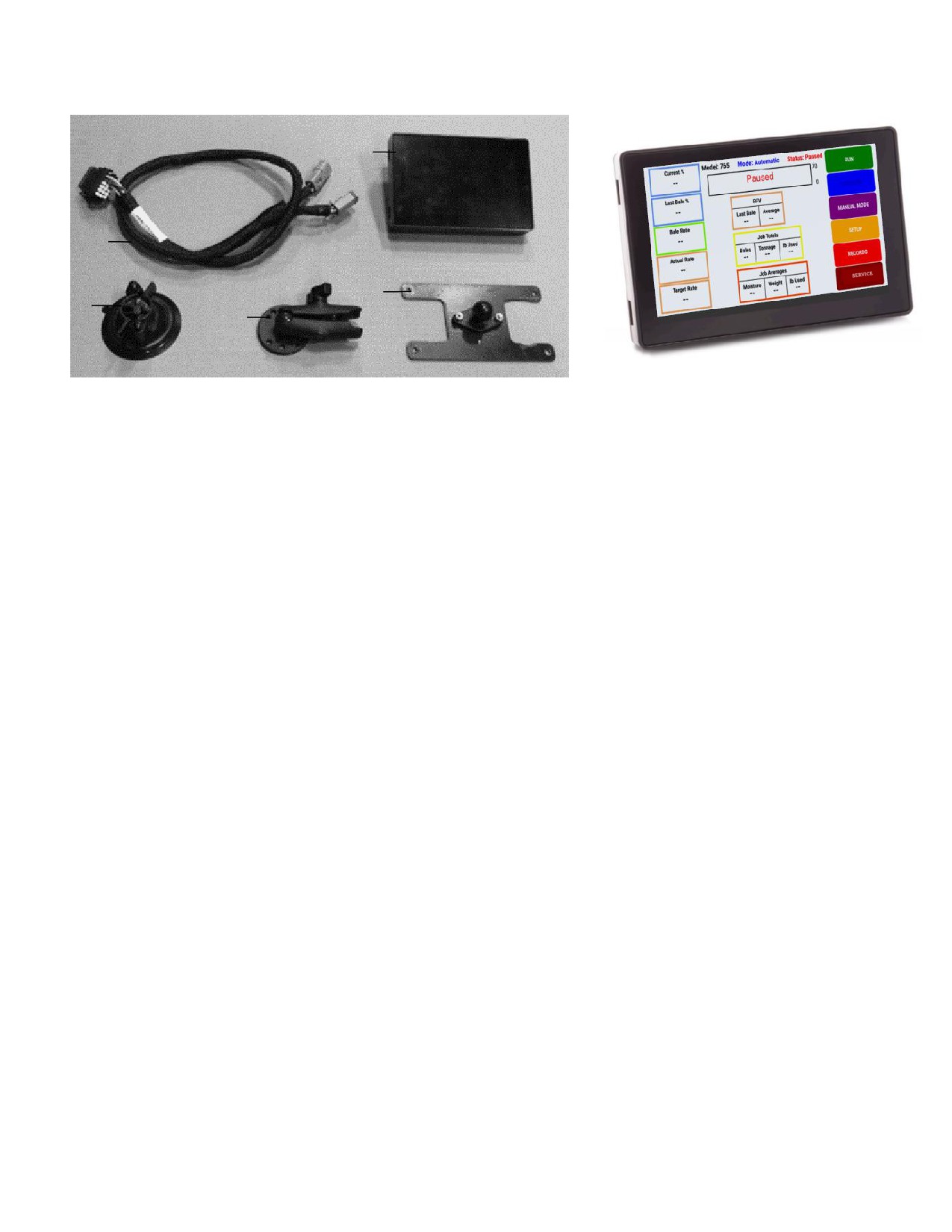
Optional Harvest Tec Display Kit (030-7670DK)
3
4
5
1
2
Ref Description
Part #
Qty
1
Suction Cup Mount
001-2012SCM
1
2
Ram Mount
001-2012H
1
3
Harvest Tec Display
006-765GVT
1
4
Display Harness
006-765GH
1
5
Mounting Plate
001-700GH
1
Installation Instructions
1. Identify 006-765GH harness connection to 006-765IC tractor harness.
2. Connect harness to the Harvest Tec Display before tightening into place.
3. Tighten the mounting and display. Streamline harness, as necessary.
4. Once connected, power cycle system and ensure display is working properly.
NOTE: CANNOT OPERATE WITH BOTH HARVEST TEC
DISPLAY AND BALER VT CONNECTED AT THE SAME TIME
32
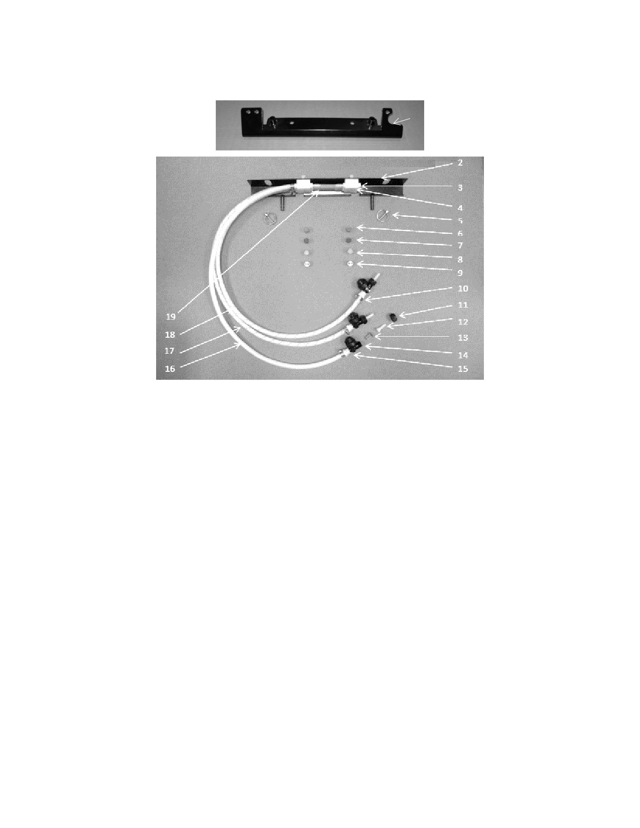
Harvest Tec Model 4636C Installation Kit
(Incudes 4536B & 6707WG4 Kits)
1
Ref Description Part Number
Qty Ref Description
Part Number Qty
1
Holder
001-4435NC
1
11 Cap
004-4723
3
2
Shield
001-4435NSX
1
12 Fitting
003-A1414VB
3
3
Fitting
003-F14
3
13 Strainer
004-1203-100
3
4
Manifold Blk
001-4435NSB
2
14 Check Valve
004-1207VB
3
5
Lynch Pin
008-4576
2
15 Fitting
003-A1414F
3
6
Tip-Red
004-T8003-PT
2
16 Clear Tubing-1/4”
002-9016
3 ft
7
Tip-Brown
004-T80015-PT
2
17 Blue Stripe Tubing
002-9016B
3 ft
8
Tip-Pink
004-T8001-PT
2
18 Green Stripe Tubing
002-9016G
3 ft
9
Tip-Stainless
004-T800067-SS
2
19 EVA-1/4”
002-9006
3 ft
10 Hose Clamp
003-9002
15
Shield Assembly
030-4636B
(Ref 1-19)
* Tip color subject to change
33
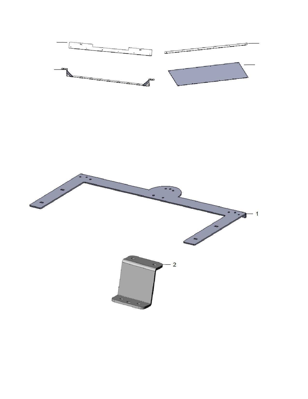
Wind Guard Assembly (4ft Baler)
20
22
23
21
Ref Description
Part Number Qty
Ref Description
Part Number
20 Wind Guard Top Bkt
001-6707MA
1
Wind Guard Kit (Ref 20-23)
030-6707WG4
21 Wind Guard Bottom Bkt
001-6707MC
1
22
4’ Wind Guard Flap
001-6707GM4
1
Complete 4636B
030-4636B
23
Backing Plate
001-6707B
2
Assembly (Ref 1-23)
Rear Light / Camera Brackets
Ref Description
Part #
Qty
1
Rear Mounting Handrail
001-6707PM
1
2
Camera Mount Bracket
001-6707PMZ
1
NP Light Extension Harness
006-7303LTX
1
34
Harvest Tec Inc. Warranty and Liability Agreement
Harvest Tec, Inc. will repair or replace components that are found to be defective within 12 months from the
date of manufacture. Under no circumstances does this warranty cover any components which in the opinion
of Harvest Tec, Inc. have been subjected to negligent use, misuse, alteration, accident, or if repairs have been
made with parts other than those manufactured and obtainable from Harvest Tec, Inc.
Our obligation under this warranty is limited to repairing or replacing free of charge to the original purchaser
any part that in our judgment shows evidence of defective or improper workmanship, provided the part is
returned to Harvest Tec, Inc. within 30 days of the failure. If it is determined that a non-Harvest Tec branded
hay preservative has been used inside the Harvest Tec applicator system where the failure occurred, then
Harvest Tec reserves the right to deny the warranty request at their discretion. Parts must be returned through
the selling dealer and distributor, transportation charges prepaid.
This warranty shall not be interpreted to render Harvest Tec, Inc. liable for injury or damages of any kind,
direct, consequential, or contingent, to persons or property. Furthermore, this warranty does not extend to loss
of crop, losses caused by delays or any expense prospective profits or for any other reason. Harvest Tec, Inc.
shall not be liable for any recovery greater in amount than the cost or repair of defects in workmanship.
There are no warranties, either expressed or implied, of merchantability or fitness for particular purpose
intended or fitness for any other reason.
This warranty cannot guarantee that existing conditions beyond the control of Harvest Tec, Inc. will not affect
our ability to obtain materials or manufacture necessary replacement parts.
Harvest Tec, Inc. reserves the right to make design changes, improve design, or change specifications, at any
time without any contingent obligation to purchasers of machines and parts previously sold.
Revised 4/17