NEW HOLLAND VM3080, VL5060, VL5070, VL5080. REPAIR MANUAL
1
R1_04 08
Machine name change
Correspondence
Previous name
New name
VL 550 Up to series 008
VL 5080 Starting from series 009
VL 540 Up to series 008
VL 5060 Starting from series 009
VL 530 Up to series 008
VM 340 Up to series 008
VM 3080 Starting from series 009
87613077B -- 07 -- 2008
3
REPAIR MANUAL
CONTENTS
Section
Description
Specifications
00
Maintenance
05
Preparing the machine
10
Thermal engine
29
Hydrostatic transmission
33
Brakes
35
Hydraulic system
39
Frame
41
Steering
44
Front axles and wheels
50
Cab
55
Electrical system
58
Harvesting equipment
60
Product feeding
74
Cleaning
80
Hoppers
88
Accessories (multipurpose)
NOTE: corresponding to machines starting from series 002.
87613077B -- 07 -- 2008
SPECIFICATIONS
1
SPECIFICATIONS
Chapter 1
CONTENTS
Section
Description
Page
Machine identification data
3
Self--propelled machine technical data
5
Harvesting equipment technical data
11
87613077B -- 07 -- 2008
2
SPECIFICATIONS
87613077B -- 07 -- 2008
SPECIFICATIONS
3
MACHINE IDENTIFICATION DATA
Model
Type
Serial no.
Machine number
VL5080
653
009
001
VL5070
653
009
001
VL5060
653
009
001
VM3080
633
009
001
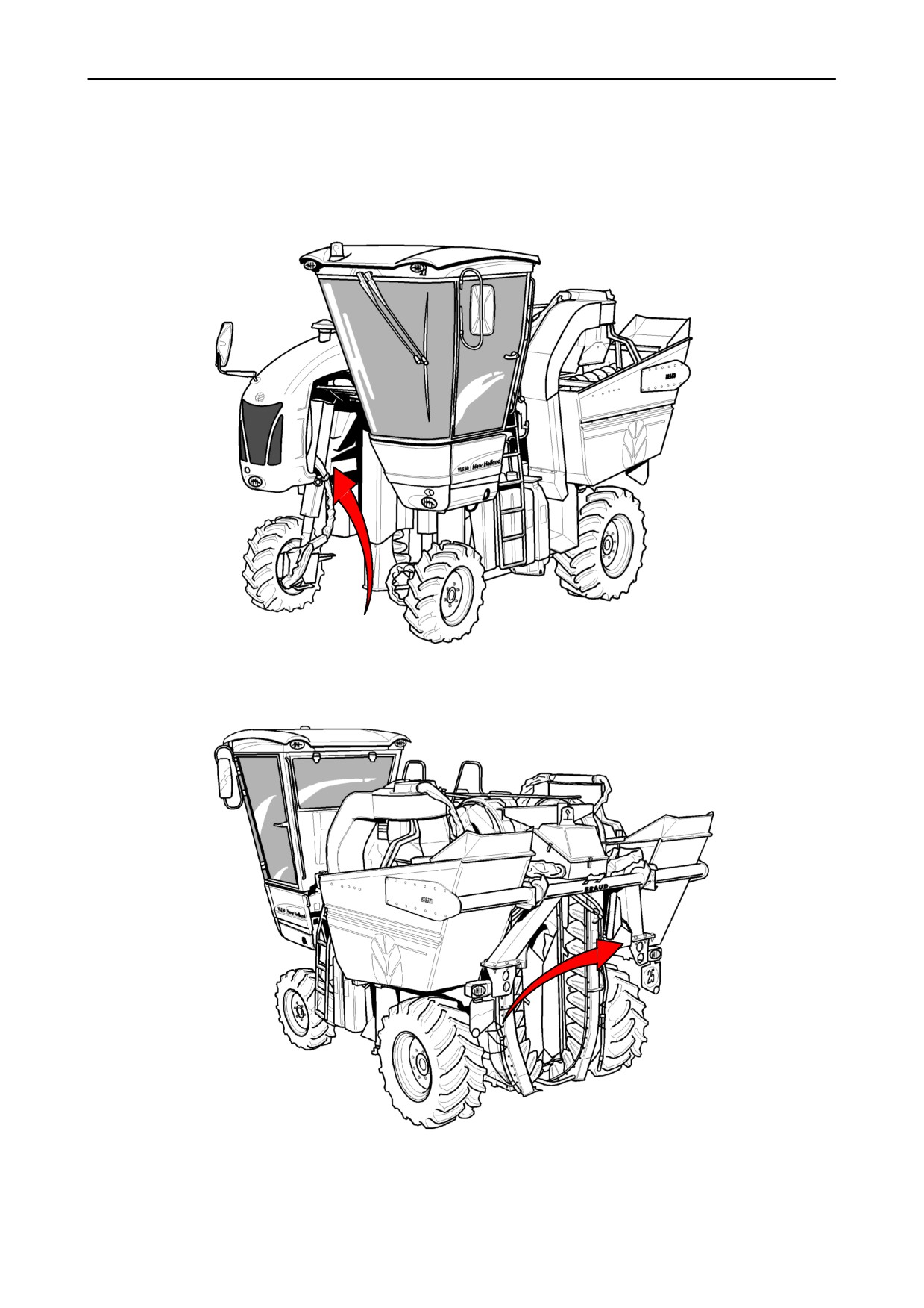
NOTE: the harvesting equipment number is the same as the self--propelled machine one.
A = manufacturer’s label
B = stamped frame number
OPERATOR’S MANUAL
Reference:
87612986
(GB)
SPARE PART CATALOGUE
Reference:
87613077B -- 07 -- 2008
SPECIFICATIONS
5
COMMERCIAL DESCRIPTION
VL5080 / 5070 /
VM3080
5060
Code
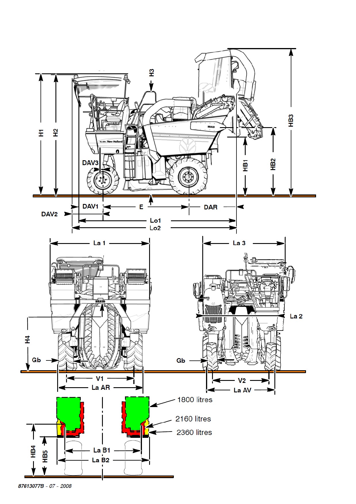
DIMENSIONS (mm)
H1
Height:
without cab
3160
3040
(at the revolving beacon)
(3745)
(3615)
H2
(harvesting equipment on with cab
the ground)
at the revolving beacon
3605
3475
H3
Harvesting equipment height at the railings
3285
3185
H4
Clearance under the harvesting equipment
from
1950 to
2450
from
1800 to 2300
HB1
Clearance under tilted up hoppers
1730
1600
HB2
Tilting axle height
2110
1980
HB3
Max. height with lifted hoppers
4620
4490
HB4
Clearance under the
hoppers, 1800 litres
1700
1550
frame
HB5
Clearance under the
hoppers, 2160 litres
--------
1150
frame
hoppers, 2360 litres
1150
--------
E
Pitch
2760
La1
Max. width at the
hoppers, 2360 litres
3000
2800
hoppers
2360 litres + cab
3000
2800
La2
Max. width from cover to
Only self--propelled
2540
2340
cover
machine
La3
Max. width from cab top
Only self--propelled
2750
2540
to right cover
machine
LaB1
Hopper width
1800 litres
2480
2290
LaB2
2160 litres
--------
2800
2360 litres
3000
--------
La
Outer width at the rear
Tyres 11.2 R24 (1)
--------
1680 + 291 = 1971
AR
wheels:
Tyres 11.2--24 T35
--------
1680 + 305 = 1985
Tyres 340/85 R24
--------
1780 + 366 = 2146
(V1 + Gb = La AR)
Tyres 420/70 R24
2090 + 431 =
2521
--------
Tyres 460/70 R24
2120 + 462 =
2582
--------
Tyres 480/65 R24 (2)
2120 + 484 =
2604
--------
La
Outer width at the front
Tyres 280/70 R20
--------
1720 + 275 = 1995
AV
wheellleve
l
on ground
:
Tyres 320/70 R20
1920 + 315 =
2235
1720 + 315 = 2035
(V2 + Gb = La AV)
(V2 at ground level)
Lo1
Max. length
without cab
4900
(5090)
without (with) des-
Lo2
with cab
4990
(5180)
temmers
DAV1
Front offset
without cab
880
DAV2
with cab
970
DAV3
Offset of front supports for multipurpose
40
DAR
Rear offset without (with) destemmers
1260
(1450)
NOTE: in road position, the noria is at 200 mm from the ground
(1) not produced anymore
(2) an additional equipment with destemmers on a VL5080 equipped with upper and lower extractors and
tyres 480 / 65 R 24 is not allowed.
87613077B -- 07 -- 2008
6
SPECIFICATIONS
COMMERCIAL DESCRIPTION
VL
VM
5080
5070
5060
3080
WEIGHTS
PTAC -- Total allowed weight under load (kg)
8000
7800
Partition
Front axle (kg)
3400
from 3100 to
3400
4700
Rear axle (kg)
from
4960 to 5200
from 4600 to
4800
Empty weight (kg) with harvesting equipment
6940
6600
6440
--
with hoppers (litres),
2400
1800
2200
standard wheels and cab, but without des-
temmers and without lower extractors.
--
with destemmers, add
(kg)
580
580
580
Weight of one wheel (kg)
Thermal engine weight (kg)
FEEDING / EXHAUST
Fuel tank
Capacity (litres)
160
Engine (cylinders) --
4
4
4
-- ISO power (kW/CV)
94/128
74/100
94/128
-- Displacement
4485
(cm3/rev.)
Air filter
Make
DONALDSON
Type
FPG090225
FPG090225
FPG090225
Engine cooling
Water capacity (litres)
Fan
D
Air/air intercooler
D
*
D
NOTE: * only with TIER 3 engine
87613077B -- 07 -- 2008
SPECIFICATIONS
7
COMMERCIAL DESCRIPTION
VL
VM
5080
5070
5060
3080
DRIVE
Variable displacement inch-
Make
REXROTH A4VG90
ing hydraulic pump
Displacement elimination
D
Control
control
Total displacement (cm3/rev.)
90
Priming pump
Displacement (cm3/rev.)
25
Capacity (l/minute), output
0.9
56.25
Front wheel motor
Make
POCLAIN
Type
MSE 05
Displacement (cm3/rev.)
688
Rear wheel motor
Make
POCLAIN
Type
MSE 11
Displacement (cm3/rev.)
843/843
Double steering valve
D
Front drive wheels in road position
D
”Twin lock” antiskid
D
Torque decrease on front wheels
optional
Max. speed in road position (km/h)
25
Max. speed in field position (km/h)
11
Hydraulic oil
Capacity (litres)
Reservoir
65
Oil type
New Holland
Hydrosystem
68
Hydrosystem 68 BIO S
Hydraulic filtering (intake/return)
D
87613077B -- 07 -- 2008
8
SPECIFICATIONS
COMMERCIAL DESCRIPTION
VL
VM
5080
5070
5060
3080
DRIVE (follows)
Conveyor and extractor
Make
SAUER
pump
Displacement (cm3/rev.)
44
Empty operating speed (rpm)
engine speed
Capacity (l/minute), output 0.9
99
Double pump
Make
SAUER
--
for shaking
Displacement (cm3/rev.)
22
Empty operating speed (rpm)
(1.02 x engine speed)
Capacity (l/minute), output 0.9
50.49
--
for steering/
Displacement (cm3/rev.)
11
lifting/hoppers
Empty operating speed (rpm)
(1.02 x engine speed)
Capacity (l/minute), output 0.9
25.24
STEERING
Hydrostatic
Type
Make
EATON
Displacement (cm3/rev.)
100
Service brake
Supplied by the hydrostatic transmission
Parking brake
(acting on the two rear wheels)
D
Park brake
manual control, on the left
Electrically--operated independent brakes
No
87613077B -- 07 -- 2008
SPECIFICATIONS
9
COMMERCIAL DESCRIPTION
VL
VM
5080
5070
5060
3080
TILTING CORRECTION
Max. tilting (%)
25
Max. tilting in road position (%)
8
Max. tilting in work position (%)
(with destemmers or special implements and front wheels
32
with ballasts)
FRAME
Harvesting header quick uncoupling
No
Link fitting possibility
D
Front and rear tracks = see relevant SB
D
PLATFORM CAB
Heated and A/C cab, optional
Optional
Activated charcoal filter
Available as spare part
ELTEC control panel
No
MC control panel
D
Pneumatic seat, optional
D
Multifunction lever: number of push buttons
11
Electrical inching control, adjusted through sensors
D
Electrical presetting for:
-- electrically--operated rear view mirrors (with cab)
D
-- CDHA
No
-- rear viewing
No
87613077B -- 07 -- 2008
10
SPECIFICATIONS
COMMERCIAL DESCRIPTION
VL
VM
5080
5070
5060
3080
LIGHTING AND WARNING LIGHTS
High/low beams
2
Front parking lights
2
Rear parking lights
2
Direction indicator
Front
2
lights
Rear
2
Side
2
Stop lights
2
License plate light
1
Reflector
Rear
2
Revolving beacons
2
Supply voltage
(V)
12
Alternator
(A)
120
Battery
(Ah)
135
92
135
Starting presetting
(A)
760
495
760
87613077B -- 07 -- 2008
SPECIFICATIONS
11
COMMERCIAL DESCRIPTION
VL
VM
5080
5070
5060
3080
HARVESTING EQUIPMENT
HARVESTING HEADER
Harvesting header hour counter
No
Type -- swinging, self--aligning
D
SDC shaking system
D
Number of shakers
14
12
12
10
Straight/elbow flexible connecting rod
13/1
11/1
11/1
9/1
Shaking start
Motor
SAUER
EATON
Displacement
22
46
(cm3/rev.)
Reducer control unit:
D
No
-- ratio
1/4
-- grease (kg)
1.2
AMBRA GR75MD
Chain
D
Toe--in adjustable from the operator’s seat
D
No
Amplitude settings
3
Removable shakers, optional
D
No
Min. clearance under the frame (mm)
1950/2450
1800/2300
Grape harvesting useful height (mm)
1050
900
Harvesting tunnel width (mm)
500
RECEIVING / TRANSPORTATION
Noria system
Large buckets
55
Small buckets
52
Fastening by rivets
2x2
1x3
Drive gears
17/58
16/59
Width of flexible stake--guides (mm)
195/265
165/235
Tightness length (mm)
1750
Harvesting min. height (mm)
150
87613077B -- 07 -- 2008
12
SPECIFICATIONS
COMMERCIAL DESCRIPTION
VL
VM
5080
5070
5060
3080
HARVESTING EQUIPMENT (follows)
Operation
Motor
EATON
Displacement
395
(cm3/rev.)
Harvesting conveyors
Width (mm)
450
Speed (rpm) max.
Reverse
D
Single operation
Motor
EATON
Displacement
31.6
(cm3/rev.)
CLEANING
2 upper extractors with removable
Diameter (mm)
430
stalk choppers
Motor
SAUER
Displacement
11
(cm3/rev.)
Speed adjustment:
D
electrically--operated
2 lower extractors (optional)
Diameter (mm)
430
No
Motor
SAUER
Displacement
6
(cm3/rev.)
Speed adjustment:
D
electrically--operated
2 independent stalk choppers, en-
Motor
EATON
abled by noria in proportional
Displacement
8.2
(cm3/rev.)
HOPPERS
Capacity (litres)
2x
900
2
x 900
--------
2 x 1080
2 x 1180
--------
Distribution auger
Motor
EATON
Displacement
31.6
(cm3/rev.)
Adjustable speed
87613077B -- 07 -- 2008
SECTION 00 -- MAINTENANCE -- CHAPTER 1
1
SECTION 00 -- MAINTENANCE
Chapter 1
CONTENTS
Section
Description
Page
Lubricant and liquid capacities
2
Thermal engine maintenance
3
Remaining grease points
5
Machine washing
7
Hydrostatic and hydraulic system maintenance
11
Routine maintenance and winter storage
13
87613077B -- 07 -- 2008

2
SECTION 00 -- MAINTENANCE -- CHAPTER 1
LUBRICANT AND LIQUID
CAPACITIES
Quantity
Corresponding
Item to be supplied
dm3
Recommended product
international
(litres)
classification
Self--propelled machine
Grease
Lithium--calcium based
grease fittings
AMBRA GR 9
grease, consistency NLGI 2
Harvesting machine grease fit-
Grease
24 cartridges
tings
Food type
re. 62777339
Noria ECU
1
Shaking rear connecting rod
Grease
Teflon silicone grease
articulations
Sitef degree 3
410--g cartridge, re.
920019780
Shaking ECU
1.2 kg
GR 75 MD
Re. 661874
molybdenum bisulfide grease,
NH 720 A
consistency NLGI 2
Engine sump and filter/s
Oil
SAE 15W40
NH 330H
4--cylinder engine
9.5
AMBRA MASTER GOLD
API CI -- 4CH -- 4
HSP
15W -- 40
ACEA E3/E5
Reservoir
65
Oil
ISO 68
AMBRA
DIN 51524 -- part 2
HYDROSYSTEM 68
Cooling system
20
AMBRA
AGRIFLU (50%) +
clean water (50%)
NOTE: the integrated joints of the rear shaking flexible connecting rods do not require greasing.
87613077B -- 07 -- 2008
SECTION 00 -- MAINTENANCE -- CHAPTER 1
3
THERMAL ENGINE MAINTENANCE
a)
After the first 50 hours
c)
Every 400 hours, or before each harvest-
ing season, replace:
--
engine oil,
--
Let the engine run until it reaches the stan-
--
replace oil filter cartridge/s,
dard operating temperature.
--
replace diesel oil filter cartridge/s.
--
Check the belt tension.
--
Replace diesel oil filter cartridge/s.
--
Check the radiator core cleanliness.
--
If the air filter clogging indicator comes on,
--
Check alternator and compressor belt ten-
clean the main cartridge by compressed air,
sion.
blowing inside out.
Be careful not to use a pressure over 6 bar;
--
Check engine tightness.
shift the nozzle downwards and hold it at
about 3 cm from the paper.
d)
Only before each campaign:
b)
Every day, or every 10 hours, check:
--
replace the air filter main cartridge.
e)
Every 1200 hours:
--
oil level,
--
adjust the tappets.
--
Adjust the injector setting.
--
coolant level,
NOTE: the diesel oil filter cartridges should be re-
--
check the cleaning conditions of the radiator
placed more often if the diesel oil conditions require
core.
it.
87613077B -- 07 -- 2008
4
SECTION 00 -- MAINTENANCE -- CHAPTER 1
87613077B -- 07 -- 2008
SECTION 00 -- MAINTENANCE -- CHAPTER 1
5
GREASE POINTS -- VL5080 VL5070 VL5060 and VM3080
Position and number of grease fittings
Greasing frequency
10 h
50 h
SELF--PROPELLED MACHINE
Front legs 2 x 3
6
Steering cylinder articulation
2
Steering relays
2
Steering bar ball joints
4
Rear wheel link articulation 2 x 2
4
Rear lifting cylinder articulation 2 x 2
4
Total: 22
HARVESTING EQUIPMENT
Shaking front plate 2 x 2
4
Shaking control connecting rods 2 x 2
4
Shaking shaft bearing 1 (or 2x1*)
1
(2*)
Left side noria shaft bearing 1
1
Belt bearings 2 x 4
8
Hopper tilting cylinder 2 x 1
2
Hopper articulation 2 x 1
2
Harvesting equipment rear articulation 1
1
Lower stalk chopper 2 x 1
2
Total 25 (26*)
(*) depending on shaking type
87613077B -- 07 -- 2008
6
SECTION 00 -- MAINTENANCE -- CHAPTER 1
A
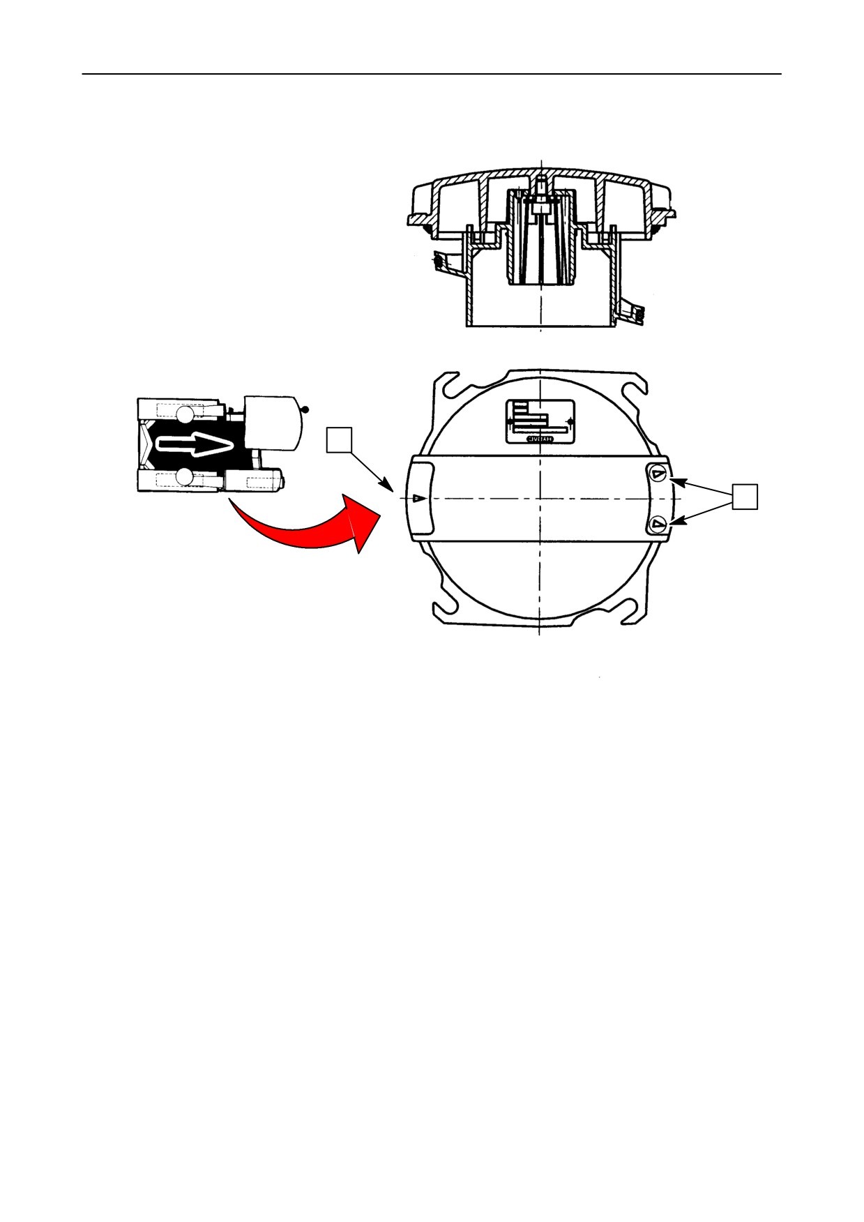
B
Hydraulic filter cover
During reassembly, pay attention to the assembly
direction:
--
the (A) side with only one arrow on the cover
must be directed towards the return line,
--
the (B) side with two arrows on the cover must be
directed towards the intake lines.
87613077B -- 07 -- 2008
SECTION 00 -- MAINTENANCE -- CHAPTER 1
7
MACHINE WASHING
To avoid sugar deposits and harvesting equipment
MACHINE ARRANGEMENT FOR WASHING
clogging and to preserve the harvesting quality, the
AT THE END OF THE CAMPAIGN
machine must be washed once or more times a day,
especially after its utilization.
Before emptying the last hoppers, stop the thermal
The tractor unit should be cleaned with the engine at
engine.
a standstill, but for proper cleaning of the harvester
--
Alight from the driver’s seat, gain access to the
unit it is necessary to operate the norias, conveyors
inside of the harvester and cause any build--up of
and extractor fans with the machine in a permanent
crop around the shaker plates and on the rear
location. This is anyway a departure from the gen-
frame to fall into the buckets.
eral safety requirements specified in the Oper-
ator’s manual.
--
Move all the machine round and, starting from
below, remove all the accumulated dirt or scrap
This operation requires thus a special care and the
material.
absolute compliance with the following precautions:
--
Climb onto the driver’s seat and start up the en-
S first of all, this operation must be made by a
gine, the extractor fans and the conveyors. Place
single operator, skilled in the control of this
the norias in the cleaning position. Run the en-
machine.
gine for 10 seconds, then empty the hoppers.
S The machine should be at a standstill, in-
side a suitable washing area, if possible as-
phalted and levelled, by at least 5x8 m, with
a water draining system, complying with the
regulations as for environmental preserva-
tion.
The washing area should be equipped as follows:
S a hose having a minimum diameter by 35
mm, long enough for cleaning the machine
all around;
S a sufficient water flow to get a 2--m water jet,
or a motor--pump unit with high capacity, with
a water reserve of 3--4 m3;
S an adjustable nozzle to direct the water jet to
about 5 m;
S a ladder about 3.5--m high and a hook about
0.7--m long.
NOTE: the use of a high pressure cleaning machine
is definitely not recommended.
87613077B -- 07 -- 2008
8
SECTION 00 -- MAINTENANCE -- CHAPTER 1
WASHING
(in the washing area)
After entering the washing area, lower the machine
to about 10 cm from the ground and tilt the hoppers
WARNING: this is a departure from
fully. Make sure the inching lever is in neutral, engage
the general safety requirements specified in the
the hand brake, stop the thermal engine, get off the
Operator’s Manual.
driver’s seat and position the hopper safety stops.
--
Open the water supply valve, pick up the hose
--
Place the ladder in the machine rear side to reach
without the nozzle and climb onto the harvesting
the upper part of the rear arch; from this position,
equipment platform located behind the driver’s
drop the clogged or deposited sarments around
seat. From there, wash the top of the machine,
the plastic cover and in the nearby area, using
the conveyors, the hopper augers, the norias,
the hook.
etc. for about 10 minutes.
--
Then, move the ladder and place it against the
--
Get off the machine and, starting from the
pipe fastening the side plates, to release the
ground, clean, from the harvesting machine front
elastic bands holding the side plates and let the
part, the tunnel inner part:
accumulated residues fall down.
S cloth, shaking frame, shakers;
Make sure that the plate upper part folds cor-
rectly against the lower one, to prevent it
S pour in water in the right and left front deflec-
from being trapped in the hoppers during tilt-
tors, through the special openings.
ing.
--
Now go to the back of the machine, open the sa-
This operation must be carried out on both ma-
loon doors and clean the rear part of the harvest-
chine sides.
ing tunnel:
S the shaking frame assembly, washing in par-
--
Put the ladder away and remove the hopper
ticular the shaker connecting rods;
stops.
S the plates and the lower sealing sheets.
--
Detach the elastic bands from the rear sealing
--
Pour in water through the side openings of the
plates and remove any debris trapped behind.
conveyor cases.
--
Remove the possible plastic caps closing the
--
Spray a lot of water in the hoods of the lower ex-
noria rear lower part.
tractors, remaining at a sufficient distance from
the stalk choppers.
--
Climb onto the driver’s seat and operate the en-
gine at medium speed, lower the hoppers, en-
gage the extractor fans and conveyors, then
place the norias in the washing position.
DANGER: the extractor rotors are
fitted with stalk chopper knives.
--
Get off the driver’s seat leaving the harvesting
Do not try and fit the pipe or the nozzle when the
equipment in operation.
thermal engine is running.
87613077B -- 07 -- 2008
SECTION 00 -- MAINTENANCE -- CHAPTER 1
9
--
Wash carefully the machine rear outer part and
--
Operate the machine to empty the hoppers and
clean carefully the rear deflector inner part. Inject
return to the washing area.
water into the rear left and right deflectors
--
Lift the machine at half height, tilt the hoppers
through the special openings.
fully, stop the thermal engine and engage the
hand brake.
--
Get off the tractor, fit the nozzle on the water pipe
--
Lay the pipe (shut off the water supply if necess-
and open water supply. One side after the other,
ary) and get on the tractor; lift the right hopper by
direct the jet toward and around each conveyor,
about 50 cm, to clear the extractor suction hood.
paying special attention to the lateral opening of
the conveyor housings, to the plates, etc...
--
Place the left hopper in the same position.
--
Go to the back of the machine, wash thehoppers
--
Increase the engine speed at max. speed.
and the container auger end.
S Turn around the machine again and wash the
--
Get off the tractor, to recover the pipe and get on
wheel links, the wheels, the safety covers,
the harvesting equipment platform to wash the
the lower extractor outlets, the cab, etc...
extractor inner part, washing them one after the
S Shut off the water supply and open the con-
other, at intervals of 7 seconds.
veyor housing inspection doors through the
inside of the harvesting tunnel.
--
Get off the harvesting equipment platform, shut
off the water supply, climb onto the driver’s seat
--
Climb onto the driver’s seat, start the thermal en-
and stop the harvesting functions (extractors,
gine and set it to idling. Lower the machine keep-
conveyors and norias).
ing the hoppers lifted, start the extractors, the
conveyors, the shaking and norias in washing
position. Let the machine run for 2--3 minutes, so
that all excess water drops down.
Optional operation
At the end of the washing operation, the machine
Now, you can control the cleaning condi-
must undergo the daily greasing procedure.
tions of the extractor slides opening the
suitable covers, after making sure that
NOTE: after greasing, remember to reposition the in-
the stalk choppers are completely
spection doors, the plates, etc... which were opened
stopped.
during the washing operations.
87613077B -- 07 -- 2008
SECTION 00 -- MAINTENANCE -- CHAPTER 1
11
HYDROSTATIC AND HYDRAULIC SYSTEM MAINTENANCE
1) Intake and return filter cartridge replace-
ment
This cartridge must be replaced:
c) every 800 hours,
d) or every two years,
e) at each emptying.
WARNING: when topping oil up, use
the same type used for the initial filling.
2) Circuit filling -- emptying
When draining oil, work with great care and cleanli-
ness. Clean the drain and filling holes before disas-
Drain the circuit every 800 hours and at least every
sembling them, by a jet of compressed air or a clean
two campaigns.
brush and oil, so that no foreign impurities or matters
enter the circuit.
Comply with the following precautions:
Remove the drain nut under the reservoir. Empty the
a) fill the tank completely with the recommended
reservoir only.
oil, at the end of the campaign, to avoid any con-
During drain operations, replace the cartridges of the
densate build--up during the intermediate sea-
intake filter and of the return filter.
son.
The oil must be filled by means of a pump
through the quick return coupling, so as to filter
the oil, or through the suitable coupling.
b) Before the following campaign and, compulsor-
ily, before starting the thermal engine, empty
the tank partially to ensure a perfect oil settling.
DANGER: bleed the shaking pump
c) Check the oil level in the reservoir.
(see corresponding diagram in section 35).
87613077B -- 07 -- 2008