NEW HOLLAND TL70, TL80, TL90, TL100. OPERATOR’S MANUAL
OPERATOR’S MANUAL
TL70
TL80
TL90
TL100
Print No. 6036457100
3rd edition
English 07/02
COMMUNICATIONS FOR THE USER
GENERAL GUIDELINES
SAFETY
This Use and Maintenance Manual provides a guide
Safety precautions for the operator and bystanders
for the user with regard to running--in, use and main-
are shown on page vi to xii inclusive. Read the safety
tenance of the tractor.
instructions and follow recommendations and hints
before starting to use the tractor.
Read this manual carefully and keep in a convenient
place for future reference. Do not hesitate to contact
your local dealer for any queries concerning your
tractor. The dealer can provide skilled personnel,
SERVICE AFTER FIRST 50 HOURS WORK
trained by the manufacturer, original service parts
The operations required for the first service are
and all tools and equipment necessary for your ser-
shown at the end of the Manual, immediately prior to
vice requirements.
the index.
The tractor is designed as a power generator and
drive--propulsion unit for use in normal and traditional
After the first 50 hours of use, return to the dealer with
agricultural conditions.
your tractor and this Manual in order to carry out the
Manufacturer’s checks and to fill in the certificates in-
The tractor is also designed to provide maximum
cluded on pages 1 and 3). The first sheet (page 1)
performance, economic running and easy use over
must be compiled on completion of the service and
a wide range of operations. Prior to delivery, all ma-
held by the dealer. The second sheet (page 3) must
chines are carefully inspected (by both the Manufac-
be kept in the Manual for documentation and refer-
turer and your local authorised dealer), to make sure
ence purposes. Check that both copies are
that they reach the user in perfect condition. To main-
signed by both yourself and the dealer.
tain the tractor in this condition and ensure trouble--
free operation, the routine maintenance described in
Section 3 of this manual must be carried out at the
specified intervals.
SPARE PARTS
“Non--original” spare parts have not been tested or
authorised by the Manufacturer. Installment and/or
use of such products may adversely affect the trac-
CLEANING THE TRACTOR
tor’s design specifications, thereby compromising
operational safety. The Manufacturer cannot be held
responsible for any damage resulting from the use of
Your tractor is an advanced machine, fitted with an
“non--original” spare parts”.
electrohydraulic control system. Care must be taken
No modifications may be made to the tractor without
when cleaning the tractor, especially if a pressurized
written authorisation from the Manufacturer.
water cleaner is used.
J Never stand too close to the tractor or direct the
WARRANTY
water jet on electrical components, seals or intake
The tractor is guaranteed in accordance with current
openings, etc.
legislation in your country and in line with contractual
agreements reached with the dealer at the time of
sale. However, the warranty is no longer valid if the
J Never direct jets of cold water at the hot engine or
rules and instructions for the use and maintenance
exhaust. See also page 42, Section 3 (RECOMMEN-
of the tractor, described in this Manual, are not ob-
DATIONS FOR BODYWORK MAINTENANCE).
served.
iii
TRACTOR IDENTIFICATION DATA
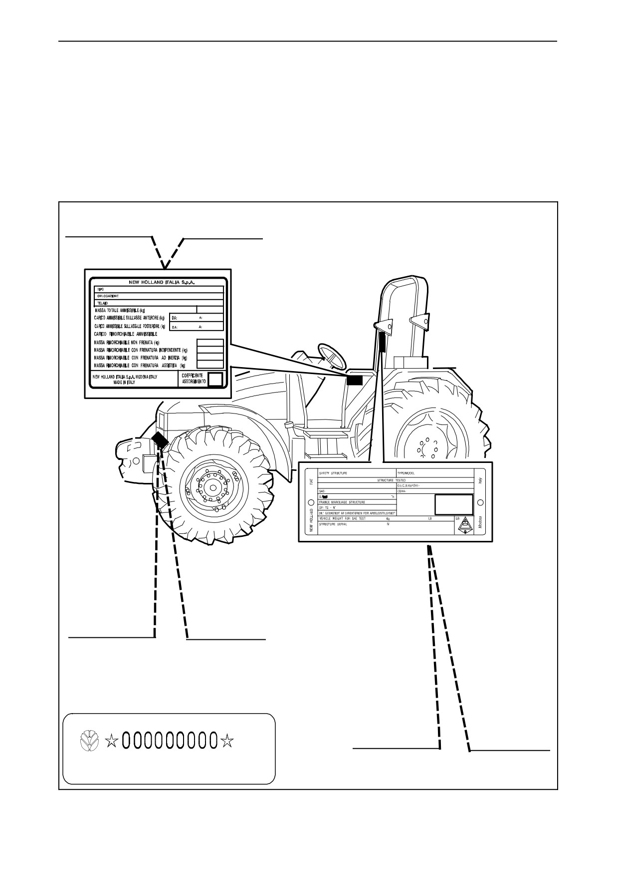
TRACTOR IDENTIFICATION
Serial numbers identify the tractor and its main components. The identification data must be supplied by the
dealer for requests for spare parts or service operations. Identification data is of fundamental importance in the
event of theft of the tractor. The location of the various identification data is shown below.
Frame and engine type identification
data plate.
Tractor frame number identification da-
ta plate (stamped on the axle support
under the bonnet).
Frame identification data plate.
iv
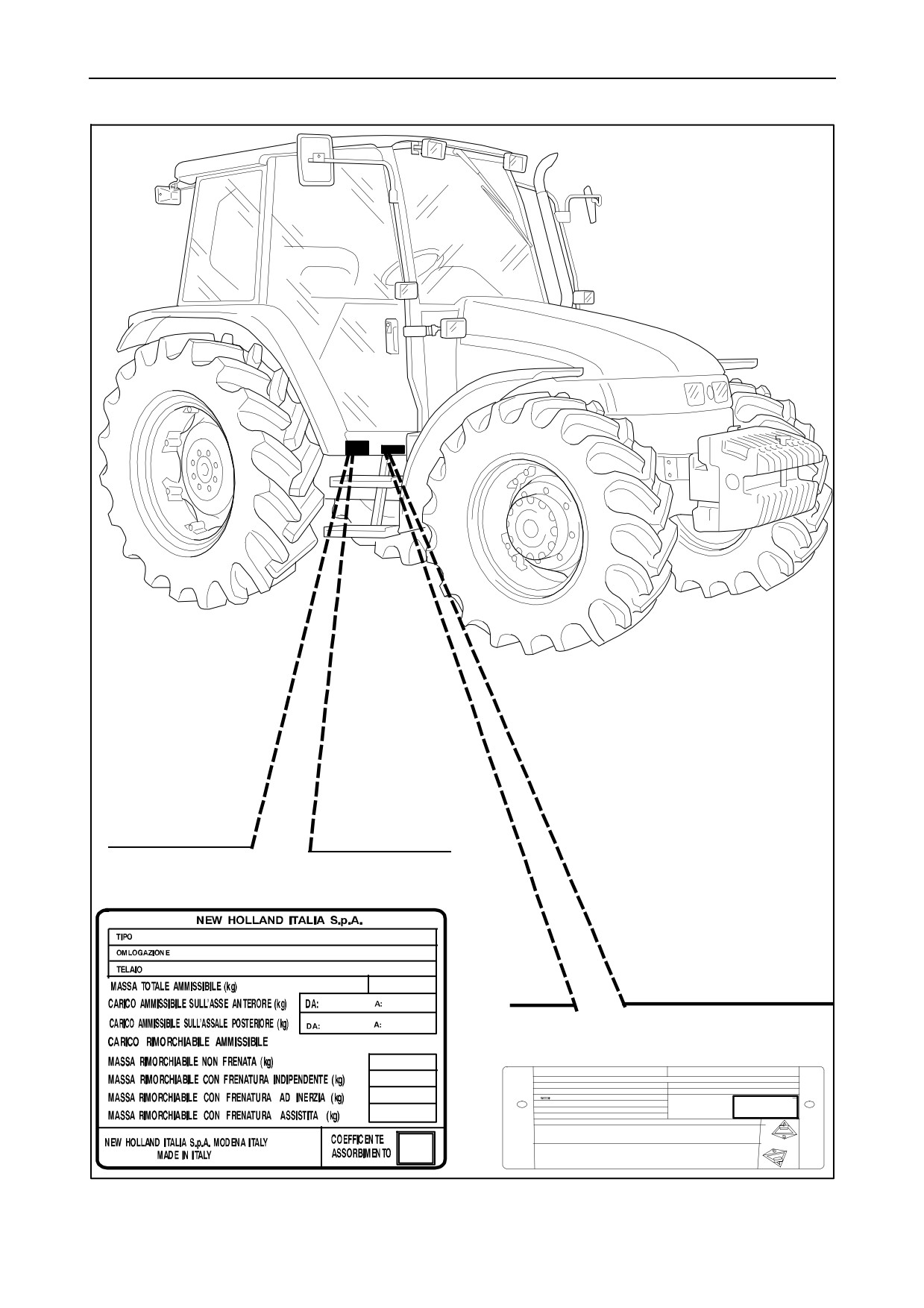
TRACTOR IDENTIFICATION DATA
Frame and engine type identification data
plate (inside the cab).
Cab identification data plate.
v
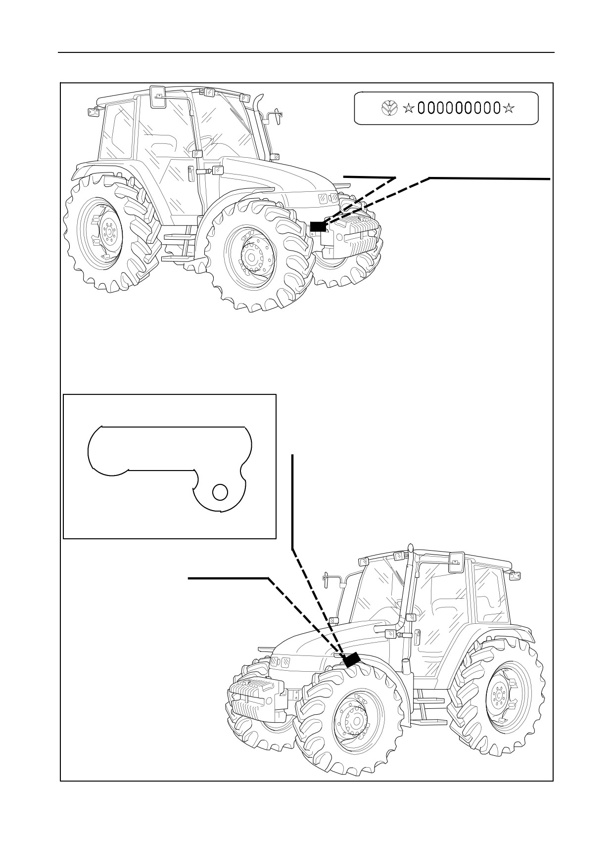
TRACTOR IDENTIFICATION DATA
Tractor frame number identification da-
ta plate (stamped on the axle support
under the bonnet).
Engine identification data plate (on en-
gine body).
vi
IMPORTANT ECOLOGICAL
CONSIDERATIONS
Soil, air and water are essential elements for agricul-
3. Modern lubricants contain additives. Do not burn
ture and for life in general. If local legislation does not
contaminated fuel oils and/or oils used in conventio-
control the treatment of certain substances, the pro-
nal heating systems.
duction of which is necessitated by advanced tech-
nologies, products derived from chemical and petro-
4. Avoid spillage when transferring used engine
chemical products must be used and disposed of ac-
cooling liquids, engine and transmission lubricants,
cording to the rules of common sense.
hydraulic oils, brake fluids, etc. Never mix used bra-
ke oil with fuel oil, or fuel oil with lubricants. Store sa-
The following recommendations may be of help:
fely until suitable disposal can be arranged according
to national legislation or local regulations.
J Find out what the relevant legislation in your
5. Modern anti--freeze liquids and solutions.
country stipulates.
anti--freeze and other additives, must be replaced
every two years. They must not be left to be
absorbed into the ground, but must be collected and
disposed of in a suitable manner.
J Ask your suppliers of lubricants, oils, fuels, anti--
freeze, detergents, etc. for information on the effects
of these products on humans and the environment
6. Do not open the air conditioning systems to carry
and for instructions concerning their use, storage
out work. These systems contain gas that must not be
and disposal. In many cases, local agricultural con-
released into the atmosphere. Contact your dealer or
sultants will be able to provide assistance.
specialised personnel, who are equipped with the ap-
propriate equipment and are authorised to re--fill the sy-
stem.
SUGGESTIONS
7. Any leakage or defect in the engine cooling or
hydraulic systems must be repaired immediately.
1. Avoid using unsuitable, pressurised filling sys-
tems or fuel cans when filling tanks, as these may
8. Do not increase the pressure in pressurised sy-
cause considerable spillage and leakage of liquids.
stems, as this may cause component parts to burst.
2. As a general rule, do not allow liquid fuels,
9. When welding, make sure that hoses are proper-
lubricants, acids, solvents, etc., to come into contact
ly protected as sparks or molten material may punc-
with the skin. The majority of these products contain
ture or weaken the tubes and sleeves, resulting in
substances that are potential health hazards.
leakage of oil, cooling liquid, etc.
vii
ALWAYS WORK SAFELY
This warning symbol points out im-
IMPORTANT WARNINGS
portant messages concerning your
safety.
The machine is designed and produced exclusively
for agricultural use.
All other use will be considered to be contrary to the
use specified by NEW HOLLAND, who cannot be
held liable for damage to property or the machine, or
Read the following safety regulations carefully and
for personal injuries which may result.
follow the recommendations in order to avoid poten-
tial hazards and safeguard your health and safety.
Persons who risk improper use will therefore assume
In this manual the symbol is accompanied by the fol-
the responsibility for any consequences arising from
lowing key--words:
such use.
Compliance with the instructions for use, mainten-
CAUTION -- When the warning is to prevent potential
ance and repairs described in this manual, are the
damage to the machine, which could also put the op-
essential preconditions for the use specified by NEW
erator’s safety at risk.
HOLLAND.
The machine must only be used, serviced or repaired
DANGER -- Specific warnings concerning potential
by personnel trained in the relevant working methods
hazards for operator safety or for other persons di-
and safety regulations and who have been autho-
rectly or indirectly involved.
rised to work on the machine.
The user must also observe the rules concerning
Failure to observe the instructions preceded by the
general safety and accident prevention, including the
aforementioned key words
(CAUTION and
Highway Code when driving on public highways.
DANGER) may result in severe or fatal injury to the
people involved.
Any arbitrary modifications made to this machine will
release NEW HOLLAND from any liability resulting
from damage or injury.
Furthermore, this manual also contains instructions
in italics preceded by the terms NOTE and WARN-
NEW HOLLAND and all distribution organisations,
ING, with the following relevance in relation to ma-
inclusive of, but not restricted to, national, regional or
chine protection:
local distributors, cannot be held liable for damage
resulting from the malfunction of parts and/or compo-
nents not approved by NEW HOLLAND.
NOTE -- Underlines the correct procedure or tech-
nique to be followed by the operator.
Under no circumstances will a guarantee be issued
for products made or sold by NEW HOLLAND that
WARNING -- Informs the operator of the danger of
are damaged as a result of the malfunction of parts
damaging the machine if the specified procedure is
and/or components not approved by NEW HOL-
not followed.
LAND.
viii
SAFETY REGULATIONS
WORKING SAFELY
GENERAL INSTRUCTIONS
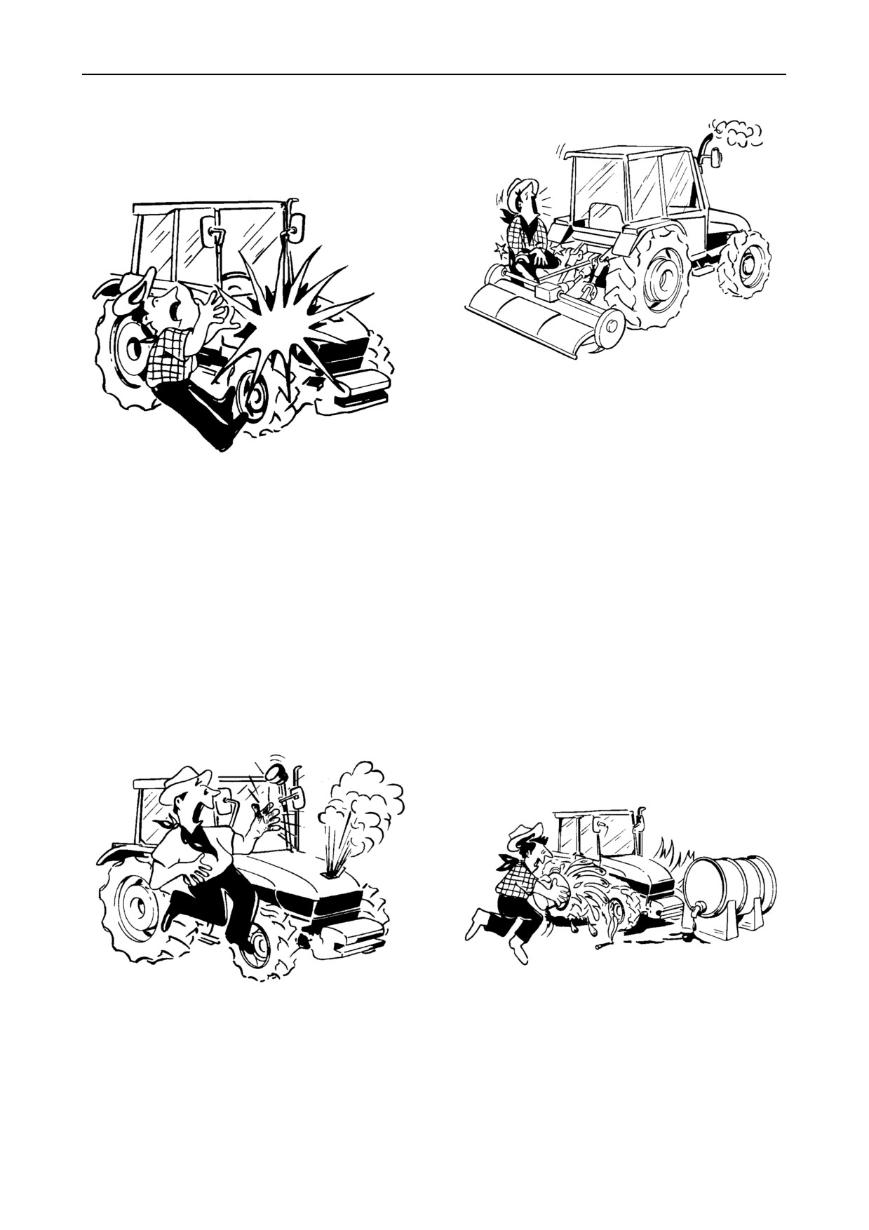
J It is advisable to keep a first aid kit on hand.
J During the manufacturing of this tractor, every
step has been taken to ensure safe operation. How-
ever, the best way to avoid accidents is to exercise
caution at all times. Once the accident has already
happened it is too late to remember what steps
should have been taken.
J The tractor must only be used by responsible per-
sonnel, trained in tractor use and authorised to oper-
ate the machine.
J Read this manual carefully before starting, using,
carrying out maintenance, refuelling or performing
any other type of operation on the tractor.
J Do not alter the injection system calibration in an
attempt to increase maximum engine speed.
J The time spent reading this manual will allow you
to get to know your tractor, thereby saving time and
effort. This will also help prevent accidents from tak-
ing place.
J Read all the safety decals on the machine and fol-
low the instructions thereon before starting, operat-
ing, refuelling or carrying out maintenance on the
machine. Promptly replace any decals that are dam-
aged, lost or illegible.
Clean the decals if they are covered by mud or de-
24266
bris.
J Do not wear loose clothing that may be trapped in
moving parts.
J Remember that the tractor is exclusively de-
Check that all rotating parts connected to the power
signed for agricultural use. Any other use will require
take--off are correctly protected.
prior authorisation from NEW HOLLAND.
ix
SAFETY REGULATIONS
J Do not alter the calibration of the pressure relief
side panels, power take--off guard, front axle trans-
valves in the various hydraulic circuits (hydrostatic
mission shaft cover, etc.).
steering, hydraulic lift, auxiliary distributors, etc.).
J Never start or manoeuvre the tractor unless
J Avoid using the tractor in unsuitable physical
seated in the driving position.
conditions, stop work instead.
J Enter and leave the tractor using the steps and
handles provided. Keep these fittings free of mud
and debris.
J Always operate with the cab or roll bar correctly
and securely fitted on the tractor: periodically check
that the fittings are not loose and that all parts of the
24135
structure are free from any damage and deformation.
Do not modify the roll bar by welding parts, drilling
holes, etc., as this could adversely affect the rigidity
of the structure.
J Before moving the tractor, always check that the
area is free of persons or obstacles.
STARTING THE TRACTOR
J Before starting the engine, check that the hand-
brake is on and that the gears and power take--off are
disengaged, even if the tractor is fitted with a start--up
safety device. Never disconnect the start--up safety
switch.If the switch does not work correctly, contact
your local dealer for eventual repair operations.
J Before starting the engine, make sure that all at-
24134
tached implements are lowered to the ground.
J Never run the engine in a closed space without
J Before starting the engine, check that all covers
ensuring adequate ventilation. Exhaust fumes are
and guards are correctly in position (roll bar, bonnet
damaging to the health and can be lethal.
x
SAFETY REGULATIONS
USING THE TRACTOR
J When the tractor is moving, the operator must re-
main correctly seated in the driving position.
J Select the most suitable wheel setting for the work
in hand, i.e.: the setting that provides the best stability.
J Never get on or off the tractor while in movement.
J When using the brakes, press the pedal down
slowly.
J Avoid curving at high speeds.
J Always use the tractor at a speed that will guaran-
tee safe operation on the type of land being worked.
When working on uneven ground, use maximum
care to ensure proper stability.
24136
J Engage the clutch slowly: if engaged too quickly,
J If you have to work with the tractor on a gradient,
especially when the tractor is getting out of a hole,
for example on hillsides, drive at moderate speed es-
ditch or operating on muddy ground or steep slopes,
pecially when taking curves.
the tractor may overturn.
Release the clutch immediately if the front wheels start
to lift.
24137
J Proceed with maximum caution when working
with the wheels near the edge of ditches or slopes.
24223
J When driving on public highways, observe the
Highway Code.
J When travelling downhill, keep the tractor in gear.
Never release the clutch and never leave the gears
J When driving, do not rest your feet on the brake
19400
in neutral.
or clutch pedals.
xi
SAFETY REGULATIONS
the lower arms or the top link of the three--point link-
age. This may result in tipping or overturning.
24138
J Never carry passengers, not even inside the cab,
unless the machine is fitted with an approved extra
24139
seat.
J When driving on roads, connect the brake pedals
using the plate provided. Braking when the pedals
J When towing, do not negotiate curves with thedif-
are not connected could cause the tractor to skid.A-
ferential lock engaged as this may prevent you from
void excessive wear on the brakes by using engine
steering the tractor.
braking.
USING IMPLEMENTS
TOWING AND TRANSPORT
AND AGRICULTURAL MACHINERY
J To guarantee tractor stability when moving, adjust
J Do not connect implements or machinery that re-
the hitching device according to the trailer or imple-
quire more power than can be generated by your
ment to be used.
tractor model.
J Drive slowly when towing extremely heavy loads.
J Never negotiate sharp curves with the power
take--off under a heavy load; this may damage the
J Foryourownsafety, donot towtrailersthat arenot
universal joints on the transmission shaft connected
fitted with an independent braking system.
to the power take--off.
J If the tractor is used to tow heavy loads, always
J Never stand between the reversing tractor and
use the hitching device and never hitch loads onto
the implement when hitching.
xii
SAFETY REGULATIONS
J When using implements that require the tractor to
J Park on flat surfaces, where possible, put the trac-
be stationary with the engine running, keep the gear
tor into gear and apply the handbrake. On slopes, in
and range levers in the neutral position, apply the
addition to applying the handbrake, put the tractor in
handbrake and use suitable wheel chocks.
first gear when facing uphill and first reverse gear
when facing downhill. As an additional safety
measure, use wheel chocks (available as an op-
tional);
this procedure is compulsory when parking with a
trailer hitched.
CAUTION: When using the 2 Speed Power
Shift with the tractor parked and the engine
switched off, the shuttle lever must be moved to the
reverse position.
24143
J Do not operate machines connected to the power
take--off without first ensuring that the operating
range of the machine is free of bystanders.
Also check that all rotating parts connected to the
24140
power take--off shaft are correctly protected.
J Add rear ballast when using lifting equipment
fitted to the front of the tractor.
SERVICING THE TRACTOR
STOPPING THE TRACTOR
CAUTION: In this manual, some illustrations
show panels or covers removed in order to
facilitate explanations.
J When the tractor is stationary, never leave con-
Never use the tractor without the panels or guards in
nected implements in the raised position. All imple-
place.
ments must be lowered before stopping the engine.
J Do not work on the tyres with unsuitable equip-
ment or without the necessary experience. Incorrect
tyre fitting may put your safety at risk.
J Before leaving the driving position, move the gear
If in doubt, contact skilled personnel.
lever to the neutral position, disengage the power
take--off, apply the handbrake, stop the engine and
engage the central clutch.
J When changing or storing tyres, make sure they
Always remove the ignition key from the dashboard
are stacked correctly and cannot roll or topple over
when leaving the tractor unattended.
causing personal injury.
xiii
SAFETY REGULATIONS
J Before removing any hydraulic lines, check that
the system is not pressurized.
24265
24141
J Before inspecting, cleaning or carrying out main-
tenance on the tractor (or any implement connected
to the tractor), always ensure that the engine is
J Leaks of pressurized oil can cause serious in-
switched off, the gears are in neutral, the brakes are
juries. When looking for leaks use the appropriate
on, the power take--off is disengaged and that all
safety equipment: screens, safety glasses and
moving parts are stationary.
gloves.
J Do not fill up the fuel tank completely if the tractor
is to work in extremely sunny conditions, as the fuel
may expand and escape. If this occurs, dry up the
J Before touching any electrical components, dis-
spillage immediately.
connect the ground lead from the battery.
24144
24142
J Only remove the radiator cap after the engine has
been allowed to cool. With the engine switched off,
use a cloth to slowly unscrew the cap and release the
pressure before completely removing the cap.
J Always keep a fire extinguisher at hand.
xiv
SAFETY DECALS
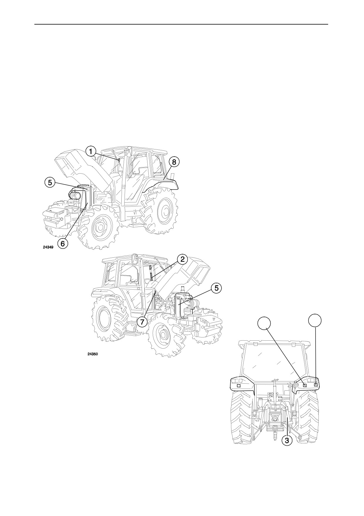
The safety decals on the following pages are posi-
the positions of the safety decals on the tractor,
tioned on your tractor in the locations shown in the
checking that their meanings are clear.
drawings below.
Read the instructions below with the tractor drivers
These safety decals are important both for your
that will operate the machine
safety and that of personnel working with you.
Keep the safety decals clean and legible. If dam-
We recommend that you study these pages and find
aged, order replacements from your dealer.
9
4
24348
xv
SAFETY DECALS
24459
3. Location: on the back
of the right--hand final
drive housing.
GENERAL WARNING:
24460
observe and respect the
indications on the safety
decals when this symbol is
1. Location: on the
present.
right--hand upright in-
side the cab.
Non--compliance with
the instructions provided
in this manual can lead to
serious injury to the oper-
ator or bystanders.
Read the instructions on
pages vi to xviii.
24461
2. Location: on the left--
hand upright inside the
4. Location: on the back of the
cab.
right--hand mudguard.
If the tractor should over-
To avoid serious injury, do not
turn, hold the steering
climb on the implement or be-
wheel tightly. Do not at-
tween the implement and the
tempt to jump out of the
tractor when the external hy-
cab.
draulic controls are enabled.
xvi
SAFETY DECALS
24104
24108
F1NN 8653 AA
6. Location: left--hand side
5. Location: left and right--
of the radiator.
hand sides of the radiator.
WARNING:
Pressurized
To avoid serious injury, keep
cooling system. Allow to cool
hands and clothing away
then remove cap carefully.
from the rotating fan, belts
Use a cloth to slowly unscrew
and any other rotating parts.
the cap and release the pres-
sure before completely re-
moving the cap.
7. Location: inside the bonnet on the right--hand
side.
To keep the braking system in good working order,
refer to the Use and Maintenance Manual. If the red
warning light on the instrument panel illuminates, there
is a fault in the braking system.
24108
xvii
SAFETY DECALS
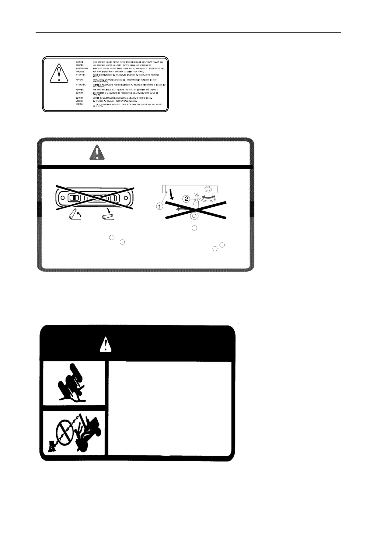
8. Location: on left--hand mudguard (only for trac-
tors without cabs).
If the tractor should overturn, hold the steering wheel
tightly. Do not attempt to jump out of the cab.
24107
WARNING
1
By activating the Lift--o--Matic control, the lift is fully raised
Only move the lever 1 with the engine switched off
or lowered.
and with the Lift--o--Matic control lowered.
By releasing the cam height limit lever
1
, the lift may be
To avoid accidents, do not climb on the implement or
fully raised.By manually movingthecamroller 2 inrever-
on the tractor whilst the Lift--o--Matic control is in
se, the lift arms will lower.
operation, whilst the height command1 is being re-
leased and when the cam roller
2
is moving.
Consult the Use and Maintenance manual for the correct height limit adjustment procedure.
9. Location: on the back of the mud flaps on the right--hand mudguard.
Before making adjustments carefully read the correct procedure noted in the
Use and Maintenance manual.
DANGER
-- If used incorrectly, the tractor may tip over or
overturn.
-- The roll bar may only be lowered for short
distances.The tractor is without protection when the
roll bar is in the lowered position.
-- Raise the roll bar and insert the lock pins immediately
after use for short distances or for transport purposes.
-- With the roll bar lowered the use of safety belts is not
advised.
-- Do not hitch cables or chains to the roll bar for towing
purposes.
-- Do not use the vehicle without the roll bar lock pins in
position if a roof has been installed.
-- The use of the roll bar and safety belts reduces the
risk of serious injury or death in the event of the tractor
tipping over or overturning.
10. Location: on the upper part of the roll bar.
xviii
STANDARDISED SYMBOLS
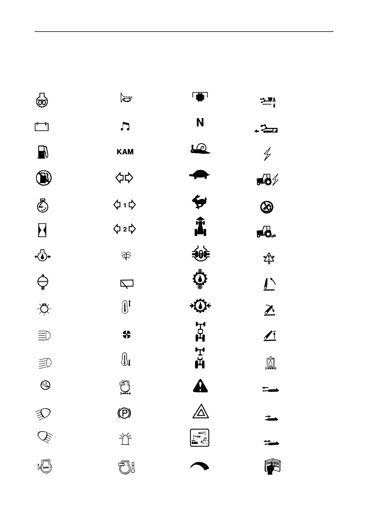
For optimal tractor use, the following symbols and definitions have been adopted in compliance with
current standardisation procedures. The symbols are followed by a brief explanatory description.
Auxiliary
Power take--off
Hydraulic lift --
starter
Horn
operating in
device
position control
Gears in neutral
Hydraulic lift --
Alternator
Radio
charge
operating in
draft control
Fuel
Creeper speed
Memory
Accessory
level
power socket
Automatic
Indicator
Slow or
fuel cut--off
Implement
lights
low speed
device
power socket
adjustment
Fast
Indicator lights
Engine speed
or high speed
on first trailer
Hydraulic
(rpm x 100)
adjustment
lift disconnected
Tractor
Indicator lights
ground
Total hours
on second trailer
% slipping
worked
speed
of rear wheels
Differential
Engine
Windscreen
Caution,
lock
oil pressure
washer/wiper
under pressure!
Open carefully
Engine
Rear transmission
Rear windscreen
Arms
coolant
oil
washer/wiper
raised
temperature
temperature
Heated air
temperature
Transmission
Lights
Arms
oil pressure
lowered
Heated
4WD engaged
Front headlights
Maximum
fan
on full beam
lifting height
Air conditioning
4WD disengaged
Front headlights
temperature
Transmission
dipped
oil filter
Brake lights
Dry air filter
Caution!
Hydraulic jack
(STOP)
extended
Front work
Parking
Hazard Lights
lights
brake
Hydraulic jack
retracted
Caution!
Rear work
Rotating beacon
Corrosive
Hydraulic jack
lights
on cab roof
substances
floating
Fault!
Refer to
Engine
Intercooler
Adjustment
Use and
coolant
temperature
control
Maintenance
level
manual
xix
TRACTOR NOISE LEVEL INFORMATION SHEET
In compliance with DPR Nº 212 enclosure 8 section IIincorporating 77/311/CEE, noise levels for tractors fitted
with tyres covered by the Use and Maintenance Manual are as specified below.
2/4WD TRACTORS WITH ROLL BARS
Maximum noise level at steering wheel
dB (A)
Model
18.64 MPH
24.85 MPH
(30 km/h)
(40 km/h)
TL70 2WD
89.5
--
TL80 2WD
91.5
--
TL90 2WD
91.5
--
TL100 2WD
89.5
--
TL70 4WD
89.5
90.0
TL80 4WD
91.5
91.5
TL90 4WD
91.5
89.5
TL100 4WD
90.0
89.5
2WD TRACTORS WITH CABS
Maximum noise level at steering wheel with cab doors
and windows:
Model
closed dB (A)
open dB (A)
18.64 MPH
18.64 MPH
(30 km/h)
(30 km/h)
TL70
78.0
82.0
TL80
77.5
81.5
TL90
78.0
81.5
TL100
77.5
81.0
xx

4WD TRACTORS WITH CABS
Maximum noise level at steering wheel with cab doors and windows:
closed dB (A)
open dB (A)
Model
18.64 MPH
24.85 MPH
18.64 MPH
24.85 MPH
(30 km/h)
(40 km/h)
(30 km/h)
(40 km/h)
TL70
78.0
77.5
82.0
82.0
TL80
77.5
78.0
82.0
81.5
TL90
78.0
77.5
81.5
82.0
TL100
77.5
78.0
81.5
81.5
WARNING -- If the noise level during continuous use reaches or exceeds 85 dB (A), the user must adopt suitable
precautions, as described in articles 41, 42, 43 and 44 of DL Nº 277 dated 15/08/1991.
xxi
SECTION 1
GENERAL INFORMATION, CONTROLS
AND INSTRUMENTS
INTRODUCTION
This Use and Maintenance Manual provides in-
All the data provided in this manual is subject to prod-
formation, documents and a practical guide for the
uct modifications. Weights and measures are to be
user with regard to running--in, use and maintenance
considered approximate figures and the illustrations
of the tractor.
do not necessarily show tractors with standard fit-
tings.
The manual is subdivided into five sections as shown
For precise information on specific tractor models
on the “Contents” page. The general index is at the
and versions, please contact your authorized dealer.
end of the manual.
The manufacturer is engaged in a continuous pro-
cess of product development and improvement and
Read and refer to this manual carefully, and always
therefore reserves the right to change the specifica-
keep it in a convenient place so that you can refer to
tions, components and prices of the product itself at
it whenever necessary.
any time, without prior notice.
In this manual, the “left--hand”and “right--hand”parts
If youhaveanydoubts inthe futureabout tractoruse,
of the tractor are as seen from the driver’s seat facing
contact your dealer.
forward.
All necessary precautions to guarantee the safety of
the operator or bystanders are listed and described
The dealer can provide skilled personnel, original
in the «Working safely» section, at the start of the
spare parts and the necessary equipment to carry
manual. Read and follow this information BEFORE
out your service requirements.
using the tractor.
1--1
GENERAL INFORMATION, CONTROLS AND INSTRUMENTS
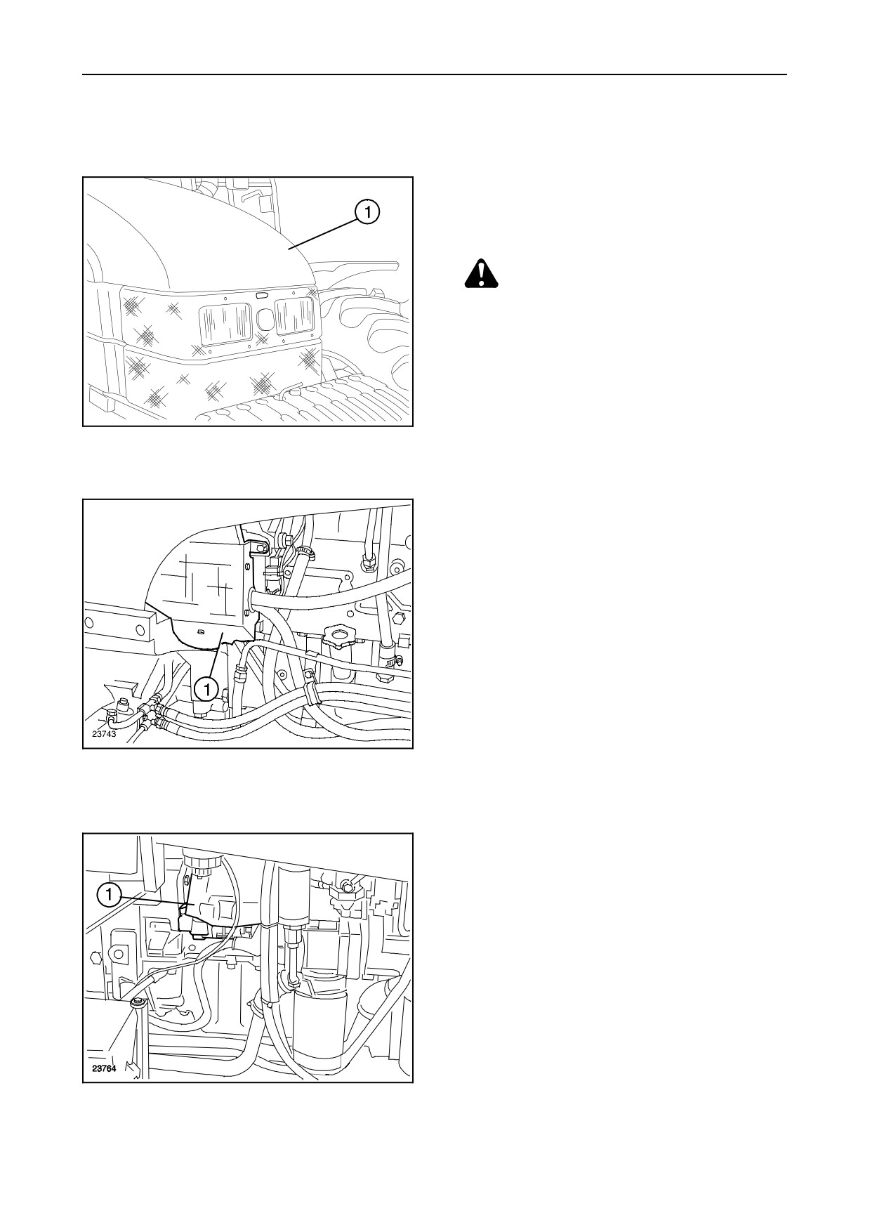
SAFETY COVERS AND GUARDS
The tractor is fitted with covers and guards for the
personal safety of the operator and others when
working.
CAUTION: Before starting the engine or
using the tractor, check that all covers and
guards are correctly in position.
27976
BONNET -- Fig. 1
1
The bonnet (1) covers the engine’s moving parts.
It must be closed before the engine is started andthe
tractor is used.
FAN COVER -- Fig. 2
Both sides of the fan have covers (1). The cover
shown in the drawing protects the left--hand side of
the fan.
2
STARTER MOTOR COVER -- Fig. 3
Cover (1) protects the electromagnetic contacts of
the starter motor from accidental contact. It must al-
ways be in place when the batteries are connected
to the electrical system.
Cover (1) protects the battery from possible damage
and the electrical connections from possible acci-
3
dental contact.
1--2
SECTION 1
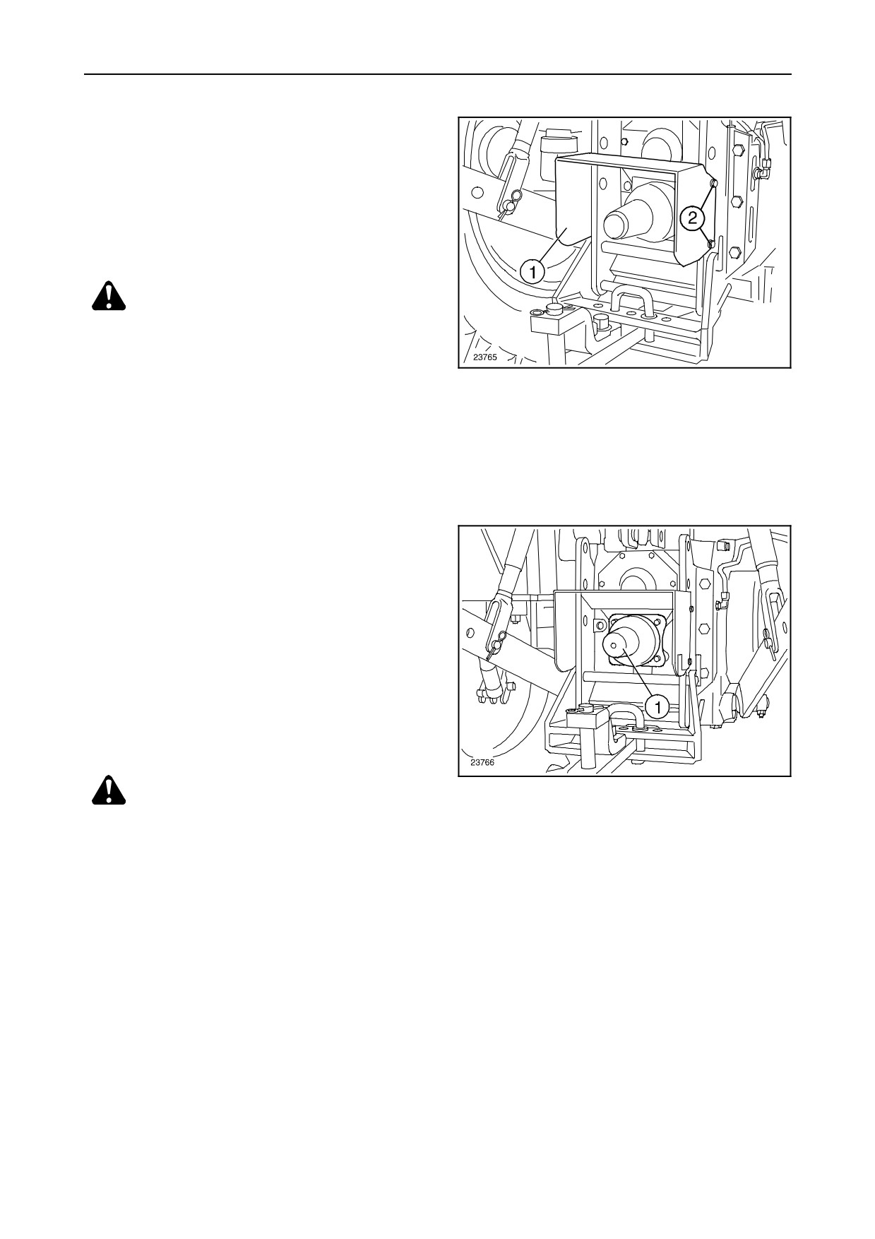
POWER TAKE--OFF GUARD -- Fig. 4
The guard (1) protects the power take--off shaft.
To facilitate replacing the shaft, loosen screws (2)
and remove the guard.
CAUTION: The guard must never be re-
moved when the tractor is in use and must
never be modified.
4
POWER TAKE--OFF SHAFT COVER
-- Fig.
5
Cover (1) must always be fitted on the power take--off
shaft when it is not connected to the implement or
machine in use.
Replace it correctly when not in use.
CAUTION: Check that all guards and covers
5
are fitted correctly before using the tractor.
1--3
GENERAL INFORMATION, CONTROLS AND INSTRUMENTS
CONTROLS AND INSTRUMENTS -- POSITION AND FUNCTION
The position and function of the controls and instru-
--
Pedal and foot plate controls.
ments on your tractor are described in the following
pages.
IMPORTANT: This section of the manual is intended
toprovidethegeneralinformation requiredby theop-
erator to locate and identify the function of individual
controls, but does not describe their use in detail. For
The controls have been sub--divided into groups and
this information, read Section 2 of the manual care-
are described as follows:
fully, relating to “Instructions for use” of controls and
instrument readings, before starting and using the
tractor.
--
Instrument panel controls (control panel).
--
Cab controls.
CAUTION: Do not use the tractor if you are
--
Operating controls, right--hand side.
not fully acquainted with the position and
--
Left--hand side controls.
operation of all the tractor controls.
1--4
SECTION 1
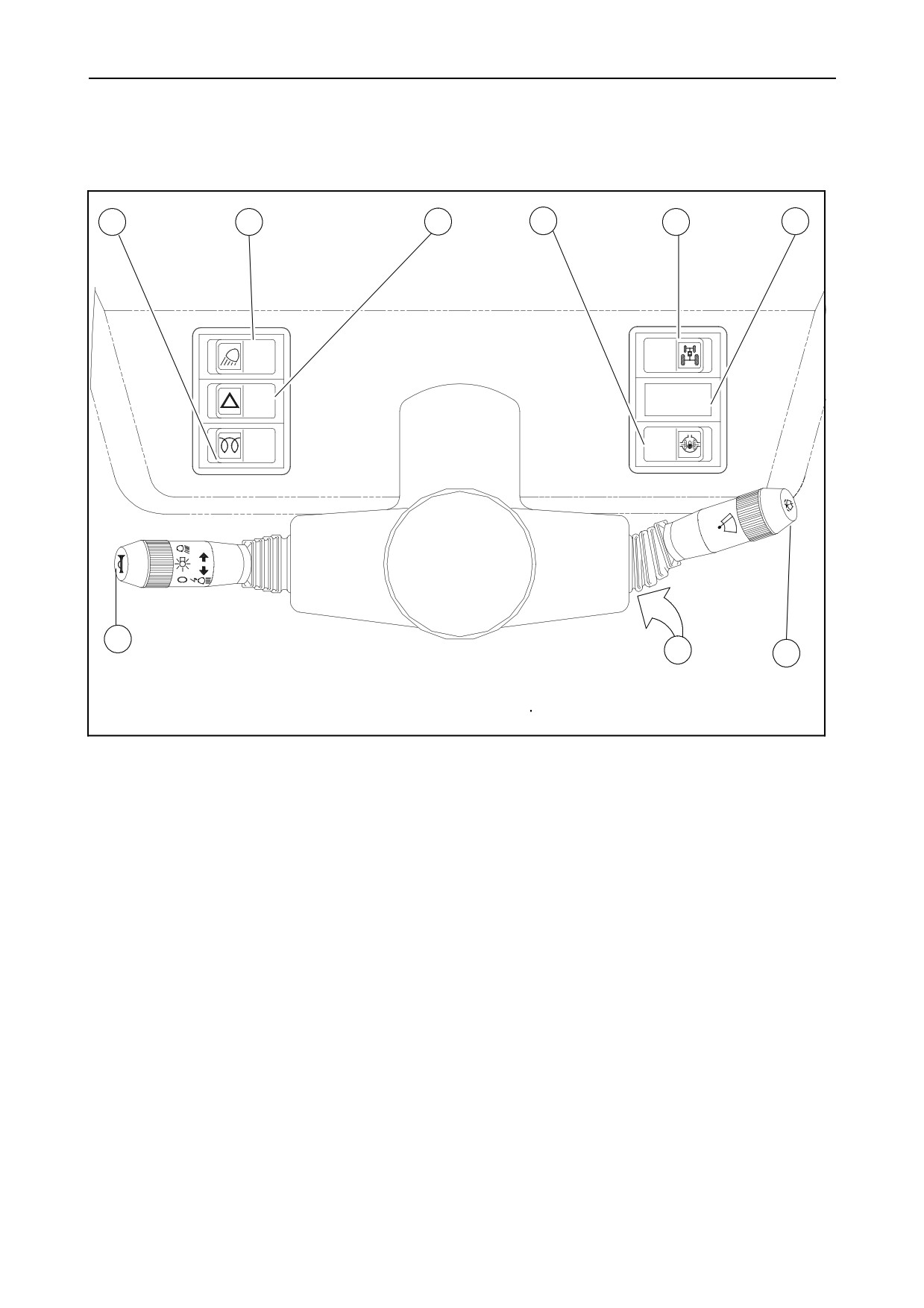
Dashboard controls
1
2
3
4
5
6
9
8
7
24258
6
Control Panel
1. Thermostart or Start -- Pilot.
6. Not used.
2. Work light switch (only for models with a cab).
7. Windscreen wiper/washer control lever
(only for models with De Luxe cab).
3. Hazard warning light switch.
8. Starter switch.
4. Differential lock switch.
9. Light control lever with direction indicators incor-
5. Four--wheel drive switch.
porated.
1--5
GENERAL INFORMATION, CONTROLS AND INSTRUMENTS
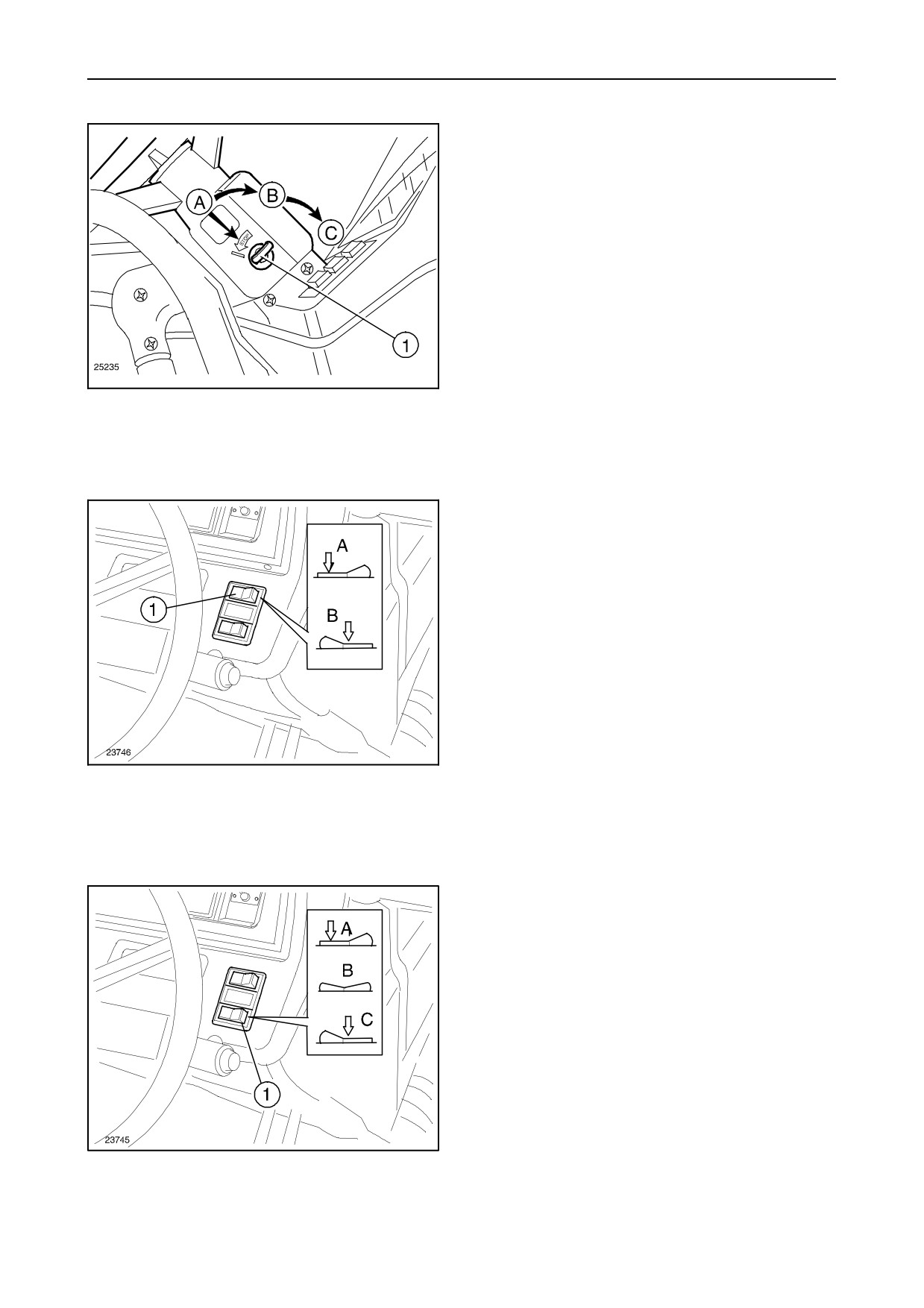
STARTER SWITCH -- Fig. 7
To operate the four switch functions, turn the key (1)
through the following positions:
A. No power supply to any of the circuits (key can
be removed). Engine stopped: automatic activa-
tion of fuel injection cut--off.
B. Stand--by for engine start up. Operation of panel
lights and instruments. Power supplied to vari-
ous circuits.
7
C. Engine start up: if released, the key returns auto-
matically to position (B).
NOTE: for further details, see page 2--3.
FOUR--WHEEL DRIVE SWITCH -- Fig. 8
Press the switch to position (B) to engage four--
wheel drive, or to position (A) to disengage.
Engagement is electro--hydraulically operated.
NOTE: for further details, see page 2--47.
8
DIFFERENTIAL LOCK SWITCH -- Fig. 9
The differential lock control is electro--hydraulically
operated and has three settings:
--
Switch in position A = lock disengaged;
--
Switch in position B = presetting for differential
lock engagement;
--
Switch in position C = differential lock engaged.
The lock is released even when only one brake
pedal is pressed, or by returning the switch to
position (A).
9
NOTE: for further details, see page 2--49.
1--6
SECTION 1
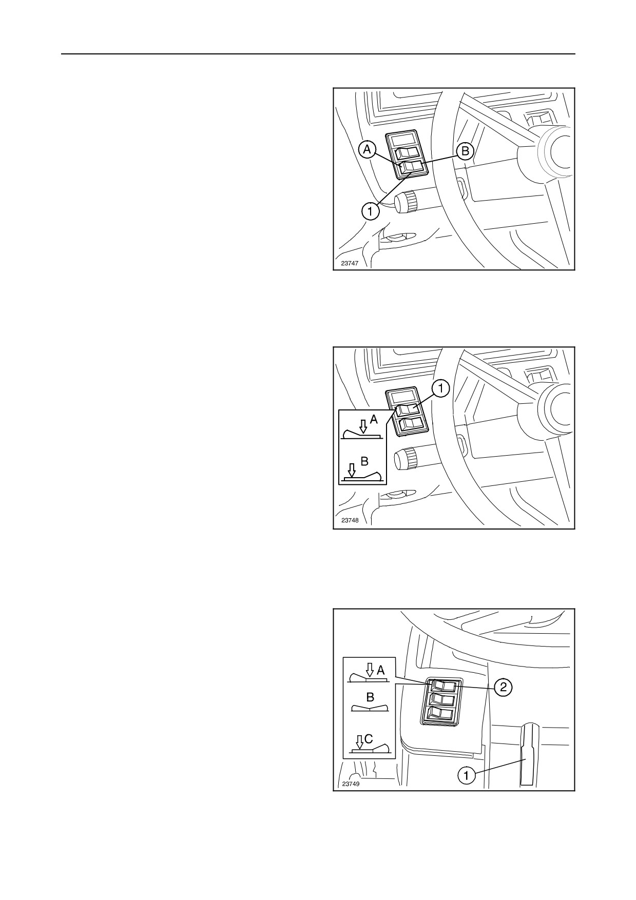
THERMOSTART OR START--PILOT
SWITCH -- Fig. 10
Press switch (1) to position A to operate the auxiliary
starting system.
When the switch is released, it returns automatically
to position B.
See instructions for starting at low temperatures,
page 2--3.
10
HAZARD WARNING LIGHT SWITCH
-- Fig. 11
Press switch (1) to the red section to turn on the
flashing hazard lights; when pressed, the switch also
flashes.
The panel light flashes at the same time as the direc-
tion indicators.
STEERING WHEEL POSITION LEVER
-- Fig. 12
11
Pull lever (1, fig. 12) to release the steering wheel
lock. Move the steering wheel up or down to find the
best position for comfortable and safe driving.
AUXILIARY LAMP CONTROL SWITCH
-- Fig. 12
There are three settings for the switch (2):
--
pressed to position A = lights OFF;
--
held in position B = rear lamps on;
12
--
pressed to position C = front and rear lamps on.
1--7