NEW HOLLAND SD440A AIR DRILL. REPAIR MANUAL
NEW HOLLAND
REPAIR
SD440A
MANUAL
AIR DRILL
SERVICE
87545777
7/06
Replaces 87354063
Service Manual Number 87545777
202
REPAIR PARTS
REPAIR PARTS IDENTIFICATION
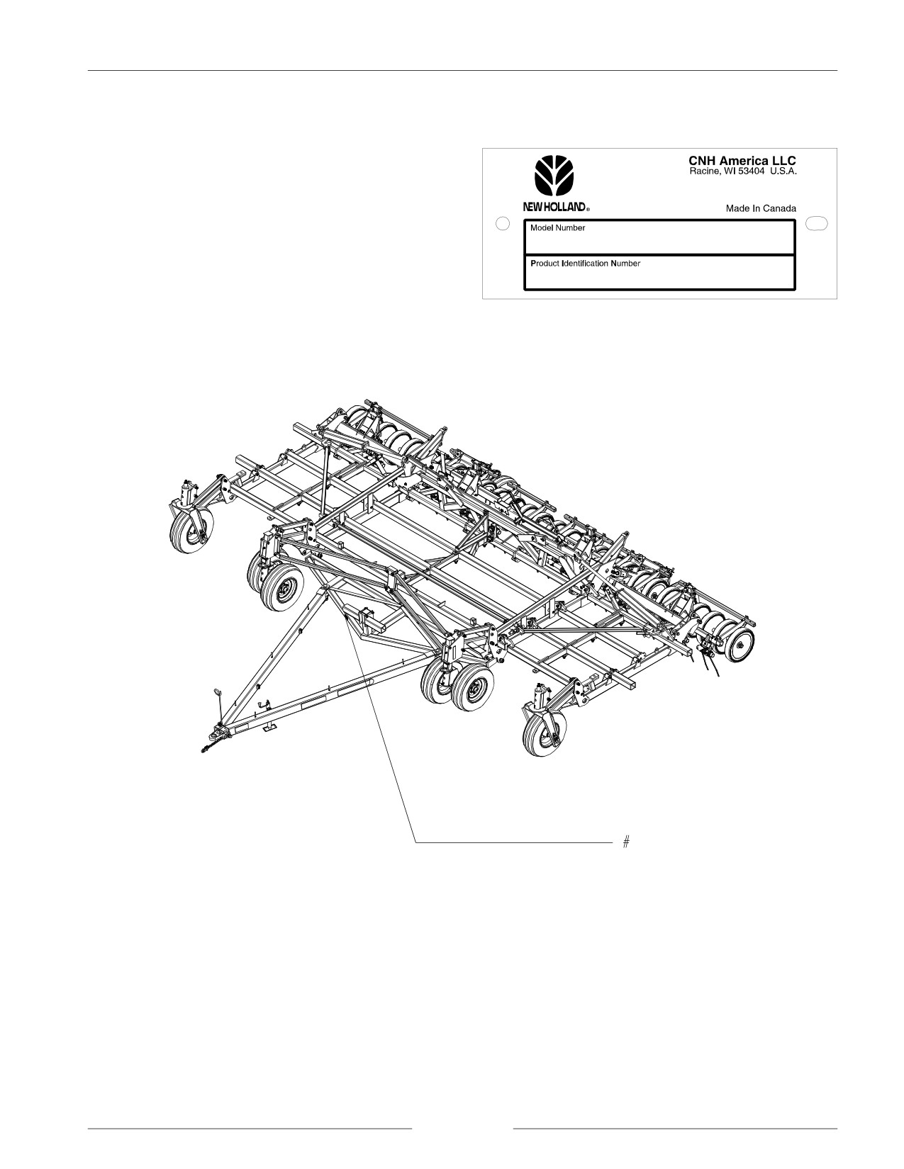
This implement has a Product Identification Number (PIN)
plate. The plate looks like the sample at right. For easy
reference, locate the PIN plate at the location shown on the
figure below. Record the number on this sheet. When
requiring repair parts, take this number into your dealer.
i
TABLE OF CONTENTS
Pages listed are a table of contents for that section
Section - Title
Page
1 - GENERAL INFORMATION
1-1
5 - ELECTRICAL
5-1
General Service Information
Connector Service Kit
Important Information
Remote Switch Installation
Service Tools
Safety
Units of Measure
6 - TRIPS, OPENERS, AND PRESS WHEEL
Bolt Torque Information
SERVICE
6-1
Machine Specifications
Service of Openers
Paint Touch-up Procedure
Press Wheels and Shanks
Ground Openers and Seed Boots
Troubleshooting Tables
2 - ADJUSTMENTS
2-1
Trip Compressor Tool Kit
Air Drill Leveling
Tension Link Kit - 550 Pound Trip
Floating Hoe/Shank Adjustments
Adjustment of Trip Assemblies
Sweep Pitch Adjustments
Trip/Shank Shim Installation
Trip Torque Specifications
Heavy Duty Bearing Kits
Setting the Depth Gauge
Press Wheel Removal
Wing Lead Adjustment
Packer Wheel Rest Assembly
Shank Spacing and Trip Release Pressure
Sweep Pitch Adjustment
3 - MECHANICAL SERVICE
3-1
Trip Torque Specifications
Troubleshooting Tables
Servicing Safety Precautions
General Operating Information
7 - AIR SYSTEM
7-1
Grease Locations
Troubleshooting Tables
Maintenance
Hoses
Tires
Theory of Operation - Air System
Caster Wheels
Determining Adequate Carrying Velocities
Caster Hub and Spindle Maintenance
Header Assemblies
Walking Beam Replacement
Hose Holder Brackets and Distribution Clamps
Caster Transport Lock Installation
Pin Guides
Depth Control Service
Walking Beam Carrier Spool Replacement
8 - ENDMARKER SERVICE
8-1
Auxiliary Tow Hitch
Endmarkers
Endmarker Replacement
Endmarker Hydraulics
4 - HYDRAULICS
4-1
Endmarker Operation and Ajdustment
Hydraulics
Replace Seals in Cylinders
Hydraulic Cylinders
Depth Control
INDEX
Wing Lift Hydraulics
iii
This Page is Left Blank
iv
SECTION 1
GENERAL INFORMATION
CONTENTS OF THIS SECTION
Page
GENERAL SERVICE INFORMATION
1-3
IMPORTANT INFORMATION
1-4
SERVICE TOOLS
1-4
SAFETY
1-5
General Safety Practices
1-6
Servicing Safety Precautions
1-6
Safety During Operation
1-7
Air and Air Hoses
1-10
Hydraulics and Hydraulic Leaks
1-10
Shields
1-11
Electrical
1-11
Tires
1-11
Safety During Transport
1-12
Safety Decals
1-12
Decal Locations
1-13
Transport Lighting Assembly
1-14
UNITS OF MEASURE
1-16
Abbreviations
1-16
Conversion Chart
1-17
BOLT TORQUE INFORMATION
1-18
MACHINE SPECIFICATIONS
1-20
Air Drill Dimensions
1-20
Machine Composition
1-21
Implement Weight
1-21
Other Specifications
1-24
PAINT TOUCH-UP PROCEDURE
1-25
page 1-1
SECTION 1 - GENERAL INFORMATION
This Page is Left Blank
page 1-2
SECTION 1 - GENERAL INFORMATION
GENERAL SERVICE INFORMATION
NOTE: Read instructions carefully before you begin.
1. Be sure to read and follow all instructions to ensure
NOTE:
If you are assembling or servicing the
proper assembly, operation, and service of the
implement inside of a building, ensure the door
implement.
opening is large enough to allow the
implement to be removed after assembly.
2. Service may require the use of a forklift or other
Check the Specifications Tables in this section
suitable lifting device.
for the overall height and width in transport
position.
3. Implement must be serviced on a flat surface.
4. Left and right direction are determined from the rear of
the implement facing the forward direction of travel.
5. Use a suitable sealant on hydraulic connections;
sealant paste is recommended. Be careful to prevent
sealant from entering the hydraulic system.
6. Apply a thread sealant to all female-to-male pipe
thread connections.
7. Do not allow tape to enter the hydraulic system.
8. Do not use a thread sealant on ORB or swivel fitting
connections.
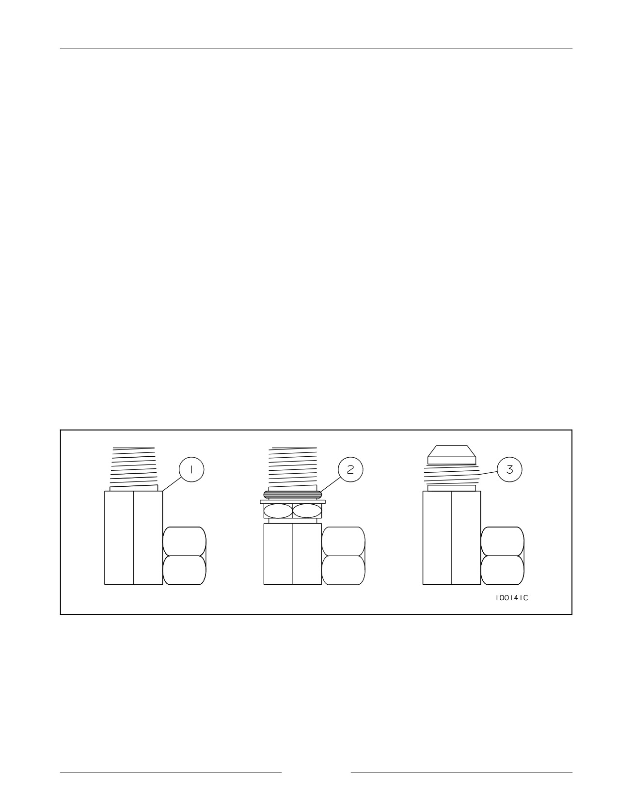
Hydraulic Fitting Identification
NOTE: Pipe thread fittings (1), O-ring boss fittings (2) and JIC fittings (3) may be the types of hydraulic fittings used.
page 1-3
SECTION 1 - GENERAL INFORMATION
IMPORTANT INFORMATION
All repair and maintenance work listed in this manual must be carried out only by qualified dealership personnel. Strictly
comply with all instructions given. Use only the specialized tools required.
Anyone who carries out the above operations without complying with the procedures shall be responsible for the subsequent
damages.
The manufacturer and all the organizations of its distribution chain, including (without limitation) national, regional, or local
dealers, reject any responsibility for damages due to the anomalous behavior of parts and/or components not approved by
the manufacturer itself. This includes those parts and/or components used for the servicing or repair of the product
manufactured or marketed by the manufacturer.
In any case, no warranty is given or attributed on the product manufactured or marketed by the manufacturer in case of
damages due to an anomalous behavior of parts and/or components not approved by the manufacturer.
The information in this manual is up to date at the date of the publication. It is the policy of the manufacturer to aim for
continuous improvement. Some information could not be updated due to modifications of a technical or commercial type,
as well as to suit the laws and regulations of different countries.
In case of disagreement, refer to your Sales and Service Networks.
SERVICE TOOLS
There are several service tools/update kits available through the parts department, for ease of servicing the air drill.
87446440
PIN GUIDES - (3) GUIDES FOR INSTALLING 1" AND 1.25" PINS
DS-200K
KIT, PRESS WHEEL PULLER - PULLING TOOL
DR-112K
KIT, TRANSPORT LOCK, SINGLE CASTER
DR-114K
KIT, TRANSPORT LOCK, DUAL CASTER
TP-950K
KIT, TRIP ASSEMBLY COMPRESSOR
87449833
WRENCH, ADJUSTING PACKER SET, CONTAINS DR-902 AND DR-903
DR-902
WRENCH, ADJUSTING PACKER LEFT
DR-903
WRENCH, ADJUSTING PACKER RIGHT
page 1-4
SECTION 1 - GENERAL INFORMATION
SAFETY
SAFETY - ALERT SYMBOL
This symbol is used to denote possible danger and care should be taken to prevent bodily injury. This symbol means
ATTENTION! BECOME ALERT! YOUR SAFETY IS INVOLVED!
THIS SYMBOL APPEARS WITH TEXT READING “DANGER!”, “CAUTION!”, OR “WARNING!” THESE
WORDS INDICATE THREE LEVELS OF POSSIBLE HAZARDS; THEY ARE DESCRIBED BELOW.
DANGER!
Indicates an imminently hazardous situation that,
if not avoided, will result in death or serious injury.
The color associated with Danger is RED.
WARNING!
Indicates a potentially hazardous situation that, if
not avoided, could result in death or serious injury.
The color associated with Warning is ORANGE.
CAUTION! Indicates a potentially hazardous situation that, if
not avoided, may result in minor or moderate
injury. The color associated with Caution is
YELLOW.
page 1-5
SECTION 1 - GENERAL INFORMATION
GENERAL SAFETY PRACTICES
REVIEW this manual and operator’s manual before
NEVER transport the air drill and air cart with product in
servicing equipment.
tank.
NEVER allow anyone unfamiliar, untrained, or
MAINTAIN YOUR AIR DRILL in proper working
complacent to operate the air drill.
condition. Unauthorized modifications to the machine
may impair function and/or safety and affect machine life.
ALWAYS USE the jack supplied when unhooking the air
drill.
BE SURE the air drill is securely fastened to a large farm
tractor or an air cart that is attached to a large farm tractor
ALWAYS ensure weight of towing vehicle is heavier than
before operating hydraulics.
implement.
USE EXTREME CARE when making adjustments.
NEVER transport the air drill at speeds higher than 25
km/hr (16 mph).
KEEP CHILDREN AWAY from all farm equipment.
SERVICING SAFETY PRECAUTIONS
BLOCK the wheels to prevent movement when servicing.
BE SURE the press wheels are blocked and wing lock pins
are in place before servicing or adjusting opener
assemblies or working on the air drill.
CAUTION!
The tractor engine should be stopped and the
wheels blocked to prevent any movement during
servicing.
Always be sure that the depth control safety lock
is in place when servicing the air drill.
Always be sure the wings are in field position
before servicing the air drill.
Escaping hydraulic fluid is a serious hazard.
Escaping hydraulic fluid that is under pressure can
penetrate the skin, causing serious injury. Relieve
pressure before disconnecting the hydraulic lines.
Check/tighten all connections before applying
pressure.
Never use your hand to search for leaks. Use a
piece of cardboard or paper. If any fluid is
injected into the skin, seek immediate medical
attention. Gangrene may result if the wound is
not treated within a few hours. Check your
hydraulic fluid containers for warnings concerning
the hydraulic fluids you use.
DO NOT walk within the radius of raised air drill
wings.
page 1-6
SECTION 1 - GENERAL INFORMATION
SAFETY DURING OPERATION
DO NOT ALLOW ANYONE ON THE AIR DRILL while
operating the air drill hydraulics.
NEVER disconnect the tractor from the drill while the
wings are not completely raised or completely lowered.
The drill should only be disconnected when it is fully in
transport or field position.
KEEP CHILDREN AWAY from the air drill during
operation.
NEVER STAND within the radius of the raised wings.
Hydraulic or mechanical failure may result in rapid or
uncontrolled falling of the wings.
RAISE AND LOWER the wings only on level ground
with the depth control fully raised.
097002S
PARK ON LEVEL GROUND and block adequately
before servicing.
AVOID moving machines.
DO NOT sit or ride on moving implements. Death or
injury may result.
098001M1
page 1-7
SECTION 1 - GENERAL INFORMATION
DISENGAGE POWER AND SHUT DOWN the tractor
engine (remove the key from the tractor ignition), be
certain that all moving parts have stopped, and all pressure
in the system is relieved BEFORE cleaning, adjusting or
lubricating the air drill.
192169C
READ the operator’s manual thoroughly.
KEEP service area clean to prevent injury to service
technicians and others.
098002M1
DO NOT enter tight areas. Be aware of pinch zones prior
to commencing work.
BE CERTAIN machine is tagged ‘out of order’ or work
area is supervised.
098003M1
BE CERTAIN all moving parts have stopped before
servicing.
098004M1
page 1-8
SECTION 1 - GENERAL INFORMATION
AVOID toxic vapors. Breathe clean air.
0960039S
DO NOT permit smoking.
196150S
WEAR protective clothing.
192078S
page 1-9
SECTION 1 - GENERAL INFORMATION
AIR AND AIR HOSES
COMPRESSOR HOSES may move unexpectedly when
suddenly disconnected.
098005M1
USE PROPER air nozzles. Do not use compressed air to
clean clothes or direct it toward any part of yourself.
098006M1
AVOID getting chemicals into eyes. Use eye protection.
098007M1
HYDRAULICS AND HYDRAULIC LEAKS
AVOID high pressure fluids.
ESCAPING HYDRAULIC FLUID IS A SERIOUS
HAZARD. Escaping hydraulic fluid under pressure can
penetrate the skin causing serious injury. Relieve pressure
before disconnecting the hydraulic lines. Check/tighten
all connections BEFORE applying pressure.
BEWARE excessive hydraulic pressure. Explosive
structural failure can result.
000002C
BEWARE air locks in cylinders. Large cylinder
displacements can occur without hydraulic oil flow.
page 1-10
SECTION 1 - GENERAL INFORMATION
SHIELDS
REPAIR damaged shields.
KEEP all shields in place.
BE EXTRA CAUTIOUS when repairing or servicing
without protective shields.
098008M1
ELECTRICAL
REMOVE the ground wire to avoid arcing contacts.
DISCONNECT wiring harnesses when welding.
098009M1
TIRES
USE A CAGE IF POSSIBLE when setting tires on rims.
AVOID excessive air pressure.
DO NOT OVER-INFLATE TIRES. NEVER lean over a
tire while inflating it.
0960041S
page 1-11
SECTION 1 - GENERAL INFORMATION
SAFETY DURING TRANSPORT
CHECK with local authorities regarding transport on
BE SURE all the wheel bolts are torqued to proper
public roads. Obey all applicable laws and regulations.
specifications before transporting the air drill.
ONLY TOW at a safe speed [25 km/hr (16 mph)]. Use
WATCH for power poles and overhead power lines.
caution when turning corners or meeting traffic.
ALWAYS lock the tractor drawbar when transporting the
BE SURE transport lighting is plugged in and that the red
air drill.
taillight(s), amber flashers, and amber signal lights are all
working properly.
ALWAYS park the air drill on level ground and block the
wheels before unhooking from the towing vehicle.
ALWAYS be certain that no one is behind or near the air
drill before moving it.
NEVER subject the air drill to steep side grades while in
transport position.
BE SURE all safety transport locks are in place before
transporting the air drill.
ALWAYS use the hitch jack supplied with the air drill
when unhooking from the tractor.
BE SURE the reflector decals are clearly visible from all
sides of the air drill and the ‘Slow Moving Vehicle’ sign is
NEVER brake or decelerate during cornering.
at the rear of the air drill in clear view of overtaking traffic.
ALWAYS enter corners slowly. SLOW the machine to
BE SURE the tractor weight is equal to or greater than the
turning speed before entering a corner. DO NOT
total weight of the air cart and air drill.
decelerate while executing the turn.
SAFETY DECALS
KEEP SAFETY DECALS CLEAN. Wipe clean when
To replace decals:
necessary.
1. Remove the old decal. Clean the area where the new
CHECK that the safety decals are not obstructed by the
decal will be affixed.
openers. If the decals are covered up, replace in a location
that is clear to view.
2. Remove the decal backing. Carefully affix the decal to
the air drill.
REPLACE missing or unreadable decals. New decals are
available from your dealer.
3. Work the air bubbles out from under the decal. Use a
clean piece of paper or the decal backing itself.
page 1-12
SECTION 1 - GENERAL INFORMATION
DECAL LOCATIONS
TC-500.08
TC-500.08
TC-500.08
TC-500.08
22903
GD-500.77
page 1-13
SECTION 1 - GENERAL INFORMATION
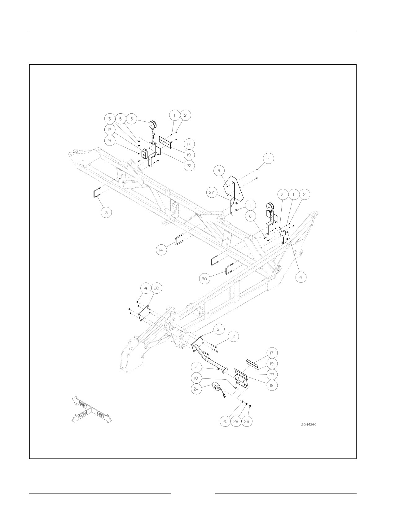
TRANSPORT LIGHTING ASSEMBLY
Transport Lighting Assembly
page 1-14

SECTION 1 - GENERAL INFORMATION
REF
DESCRIPTION
REF
DESCRIPTION
1
WASHER LOCK .313 YZD
17
DECAL RETROREFLECTIVE RED 2.0 X 9.0
2
NUT .313 UNC GR2 YZD
18
DECAL RETROREFLECTIVE AMBER 2.0 X
9.0
3
NUT .5 UNC GR2 YZD
19
SEALANT SONOLASTIC 150 BLACK
4
LOCKNUT .5 UNC GR B YZD 1-WAY, ALL
20
BACKING PLATE UNIVERSAL
METAL
5
WASHER LOCK .5 YZD
21
BRACKET AMBER LIGHT MOUNT
6
SMV SIGN STEEL BACK 4 HOLES
(ASAE
22
RED LIGHT/DECAL MNT BRACKET
S276.5) UNIVERSAL MOUNTI
7
BOLT .25 X .75 UNC GR5 YZD
23
AMBER LIGHT/DECAL MNT BRACKET
8
LOCKNUT .25 UNC GR B YZD 1-WAY, ALL
24
LIGHT AMBER WARNING ASSEMBLED
METAL
9
BOLT .313 X 1 UNC GR5 YZD
25
WASHER,.531 X 1.062 X .095
10
BOLT .5 X 1 UNC GR5 YZD
26
NUT .5 UNF GR5 YZD
11
LOCKNUT .625 UNC GR B YZD 1-WAY, ALL
27
S.M.V. SIGN BRACKET
METAL
12
BOLT .5 X 3.5 UNC GR5 YZD
28
WASHER LOCK .5 YZD
13
BOLT US .313 4.125W 4.75D UNC GR2 YZD
29
BOLT .313 X 1.5 UNC GR5 YZD
.75'' THREAD
14
BOLT US .625 4.063W 5.375D UNC GR5 YZD
30
BOLT US .5 4.125W 5.25D UNC GR5 YZD
1.5'' THREAD
1.25'' THREAD
15
LIGHT ASSEMBLY TAIL/SIGNAL RED AGTQA
31
BRACKET PLUG RECEPTICLE
16
MODULE,IMPLEMENT LGHTNG CNTRL
Transport Lighting and SMV Sign
page 1-15
SECTION 1 - GENERAL INFORMATION
UNITS OF MEASURE
ABBREVIATIONS
Acres
ac
Kilometers per hour
km/hr
Atmospheres
atm
Kilopascal
kPa
Bushel
bu
Kilowatt
kW
Centimeters
cm
Liters per hectare
L/ha
Cubic Meters
m3
Liters per minute
L/min
Cubic Feet
ft3
Liters
L
Degrees Fahrenheit
F/
Meters
m or M
Degrees Celsius
C/
Miles per hour
mph
Feet
ft
Milliliters
mL
Fluid ounces
oz
Millimeters
mm
Gallons per minute
gal/m
Newton Meters
N"m
Gallons per acre
gal/ac
Ounces
oz
Gallons
gal
Pound force inches
lbf"in
Hectares
ha
Pound force feet
lbf"ft
Horsepower
hp
Pounds per square inch
PSI
Inch
in
Pounds
lbs
Kilograms per hectare
kg/ha
Pounds per acre
lbs/ac
Kilograms
kg
Ton (short)
t
Kilometer
km
Tonne
t
page 1-16
SECTION 1 - GENERAL INFORMATION
CONVERSION CHART
ac
x
0.405
=
Hectares (ha)
L
x
0.028
=
bu
atm
x
101.325
=
kPa
L/ha
x
0.107
=
U.S. gal/ac
Bar
x
100.00
=
kPa
L/ha
x
0.089
=
Imperial gal /ac
Bar
x
14.50
=
PSI
L
x
0.264
=
U.S. gal
bu
x
35.239
=
L
L/min
x
0.220
=
Imperial gal/min
cm
x
0.39
=
in
L
x
0.220
=
Imperial gal
C°
(1.8 C°)+32
=
F°
L/min
x
0.26
=
U.S. gal/min
ft
x
0.31
=
m
lb
x
0.454
=
kg
ft3
x
0.03
=
m3
lbf Cft
x
1.356
=
N Cm
F°
(F°-32) x(0.556)
=
C°
lbf Cin
x
0.113
=
N Cm
ha
x
2.471
=
ac
lbs/ac
x
1.121
=
kg/ha
hp
x
1.746
=
kW
m
x
3.281
=
ft
Imperial
x
0.96
=
U.S. oz
m3
x
35.34
=
ft3
ounces
Mile
x
1.609
=
km
Imperial oz
x
28.413
=
mL
mL
x
0.035
=
Imperial oz
Imperial oz
x
0.006
=
Imperial gal
mL
x
0.034
=
U.S. oz
Imperial gal
x
11.234
=
L/ha
mm
x
0.039
=
in
/ac
mph
x
1.609
=
km/hr
Imperial
x
4.546
=
L/min
gal/min
N Cm
x
8.851
=
lbf Cin
Imperial gal
x
160.000
=
Imperial oz
N Cm
x
0.738
=
lbf Cft
Imperial gal
x
1.201
=
U.S. gal
PSI
x
0.069
=
Bar
Imperial gal
x
4.546
=
L
PSI
x
6.895
=
kPa
Imperial gal
x
1.201
=
U.S. gal/ac
short t
x
0.907
=
t
/ac
t
x
1.10
=
short t
in
x
25.400
=
mm
U.S. gal/min
x
3.785
=
L/min
in
x
2.540
=
cm
U.S. oz
x
1.04
=
Imperial oz
kg
x
2.210
=
lb
U.S. gal/ac
x
0.833
=
Imperial gal /ac
kg/ha
x
0.892
=
lbs/ac
U.S. oz
x
0.008
=
U.S. gal
km/hr
x
0.621
=
mph
U.S. gal/ac
x
9.356
=
L/ha
km
x
0.621
=
Mile
U.S. gal
x
128.000
=
U.S. oz
kPa
x
0.145
=
PSI
U.S. oz
x
29.57
=
mL
kPa
x
0.010
=
atm
U.S. gal
x
0.83
=
Imperial gal
kPa
x
0.010
=
Bar
U.S. gal
x
3.79
=
L
kW
x
1.358
=
hp
page 1-17
SECTION 1 - GENERAL INFORMATION
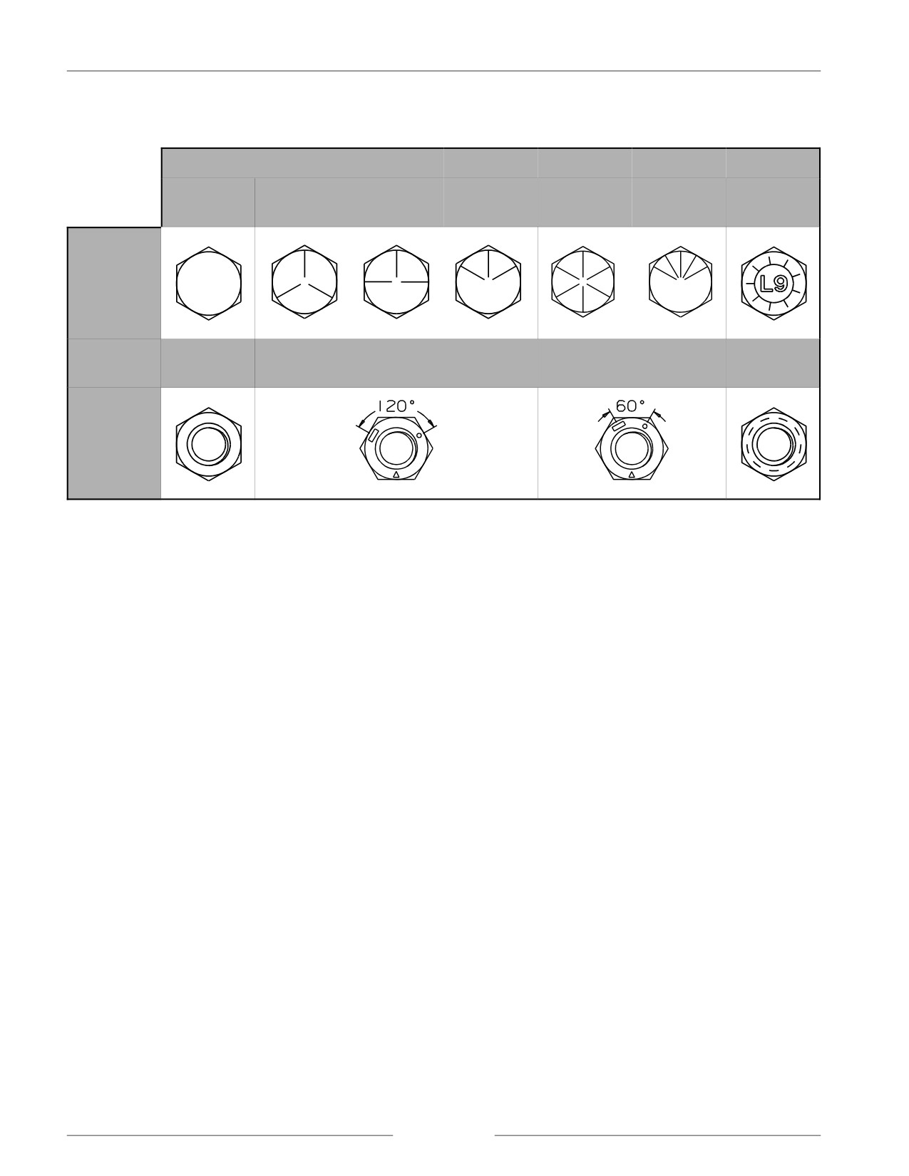
BOLT TORQUE INFORMATION
GRADE
1 OR 2
5
5.1
5.2
8
8.2
L9
(ALLOY)
SAE
MARKINGS
FOR
BOLTS
AND CAP
SCREWS
2
5
8
L9
(ALLOY)
SAE
MARKINGS
FOR HEX
NUTS
Bolt and Nut Grade Information
1. Fasteners should be replaced with the same or higher grade. If higher grade fasteners are used, these should only be tightened
to the strength of the original.
2. Make sure the fastener threads are clean and that thread engagement is started. This will prevent them from failing when being
tightened.
3. Tighten plastic insert or crimped steel-type lock nuts to approximately 50 percent of the dry torque; applied to the nut, not to
the bolt head. Tighten toothed or serrated-type lock nuts to the full torque value.
4. The L9 (Alloy) fasteners torque values are for a bolt, nut, and two washers.
NOTE: When using L9 (Alloy) fasteners, do not use the values in this table for tapped holes.
page 1-18

SECTION 1 - GENERAL INFORMATION
GRADE 2*
GRADE 5, 5.1, OR 5.2
GRADE 8 OR 8.2
L9 (ALLOY)
Dry **
Lubricated**
Dry **
Lubricated**
Dry **
Lubricated**
Head
Nut
SIZE
NAm
lbfAft
NAm
lbfAft
NAm
lbfAft
NAm
lbfAft
NAm
lbfAft
NAm
lbfAft
NAm
lbfAft
NAm
lbfAft
1/4 UNF
7.5
5.5
5.7
4.2
10.8
8
8.5
6.3
16.3
12
12.2
9
13.6
10
14.9
11
1/4 UNC
8.5
6.3
6.4
4.7
13.6
10
9.8
7.2
19
14
13.6
10
16.3
12
17.6
13
5/16 UNF
15
11
11
8
23
17
18
13
33
24
24
18
26
19
28
21
5/16 UNC
16
12
12
9
26
19
19
14
37
27
27
20
27
20
31
23
3/8 UNF
27
20
20
15
41
30
31
23
61
45
47
35
41
30
45
33
3/8 UNC
31
23
23
17
47
35
34
25
68
50
47
35
47
35
52
38
7/16 UNF
43
32
33
24
68
50
47
35
95
70
68
50
75
55
81
60
7/16 UNC
49
36
37
27
75
55
54
40
108
80
81
60
81
60
88
65
1/2 UNF
68
50
47
35
102
75
75
55
149
110
108
80
115
85
129
95
1/2 UNC
75
55
54
40
115
85
88
65
163
120
122
90
129
95
142
105
9/16 UNF
95
70
75
55
149
110
108
80
203
150
149
110
163
120
190
140
9/16 UNC
108
80
81
60
163
120
122
90
231
170
176
130
183
135
203
150
5/8 UNF
136
100
102
75
203
150
149
110
285
210
217
160
231
170
251
185
5/8 UNC
149
110
115
85
231
170
176
130
325
240
244
180
258
190
278
205
3/4 UNF
237
175
176
130
353
260
271
200
515
380
380
280
359
265
393
290
3/4 UNC
271
200
190
140
407
300
298
220
570
420
420
310
447
330
481
355
7/8 UNF
231
170
170
125
583
430
434
320
814
600
610
450
644
475
685
505
7/8 UNC
244
180
190
140
637
470
475
350
909
670
678
500
705
520
793
585
1 UNF
339
250
258
190
868
640
651
480
1234
910
922
680
746
550
1051
775
1 UNC
380
280
285
210
976
720
732
540
1383
1020
1031
760
949
700
1220
900
1-1/8 UNF
475
350
366
270
1071
790
800
590
1749
1290
1315
970
1390
1025
1559
1150
1-1/8 UNC
542
400
407
300
1207
890
909
670
1953
1440
1464
1080
1559
1150
1797
1325
1-1/4 UNF
678
500
515
380
1519
1120
1139
840
2468
1820
1844
1360
1898
1400
2170
1600
1-1/4 UNC
746
550
570
420
1681
1240
1261
930
2726
2010
2048
1510
2170
1600
2373
1750
1-1/2 UNF
1180
870
881
650
2644
1950
1980
1460
4285
3160
3214
2370
3932
2900
4407
3250
1-1/2 UNC
1329
980
990
730
2983
2200
2224
1640
4827
3560
3621
2670
4475
3300
4949
3650
Bolt Torque Information
DO NOT use these values if a different torque value or tightening procedure is given for a specific application. Torque values listed are for
general use only. Check tightness of fasteners periodically. Shear bolts are designed to fail under predetermined loads. Always replace shear
bolts with identical grade.
** "Lubricated" means coated with a lubricant such as engine oil, or fasteners with phosphate and oil coatings. "Dry" means plain or zinc
plated without any lubrication.
* Grade 2 applies for hex caps (not hex bolts) up to 6" (152 mm) long. Grade 1 applies for hex cap screws over 6" (152 mm) long, and
for all other types of bolts and screws of any length.
page 1-19
SECTION 1 - GENERAL INFORMATION
MACHINE SPECIFICATIONS
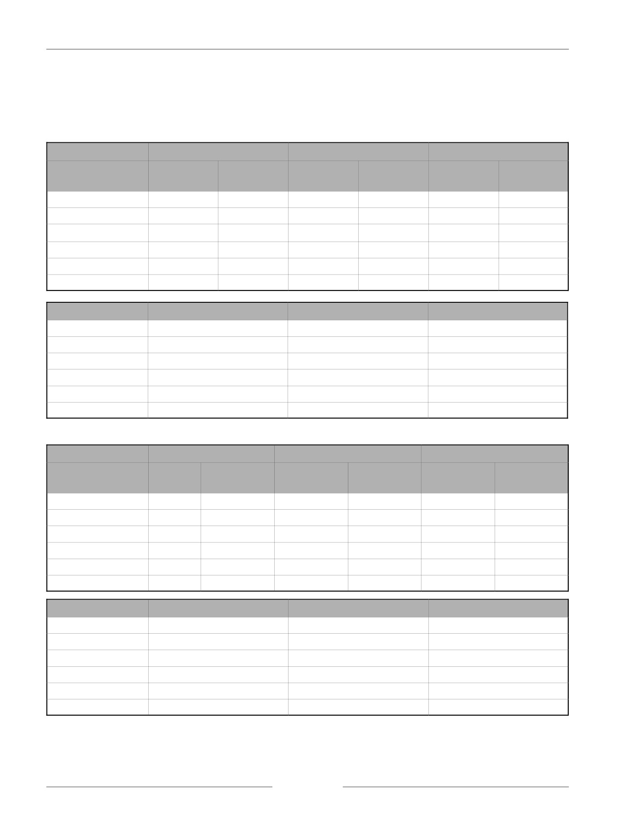
AIR DRILL DIMENSIONS
Metric Dimensions (Meters)
7.2" SPACING
10" SPACING
12" SPACING
BASE MACHINE
# OF
WIDTH OF
# OF
WIDTH OF
# OF
WIDTH OF
SHANKS
CUT
SHANKS
CUT
SHANKS
CUT
8.2
45
8.2
34
8.6
28
8.5
10.1
55
10.1
40
10.2
34
10.4
11.9
65
11.9
48
12.2
40
12.2
13.7
75
13.7
56
14.2
46
14.0
15.5
85
15.5
62
25.7
52
15.9
17.4
95
17.4
70
17.8
58
17.7
BASE MACHINE
TRANSPORT WIDTH (1)
TRANSPORT HEIGHT (2)
AIR DRILL LENGTH
8.2
5.8
3.6
8.3
10.1
5.8
4.5
8.3
11.9
5.7
5.4
8.3
13.7
5.8
4.4
9.7
15.5
5.8
5.3
9.7
17.4
5.8
5.3
9.7
Imperial Dimensions (Feet)
7.2" SPACING
10" SPACING
12" SPACING
BASE MACHINE
# OF
WIDTH OF
# OF
WIDTH OF
# OF
WIDTH OF
SHANKS
CUT
SHANKS
CUT
SHANKS
CUT
27
45
27
34
28.3
28
28.0
33
55
33
40
33.3
34
34.0
39
65
39
48
40.0
40
40.0
45
75
45
56
46.7
46
46.0
51
85
51
62
51.7
52
52.0
57
95
57
70
58.3
58
58.0
BASE MACHINE
TRANSPORT WIDTH (1)
TRANSPORT HEIGHT (2)
AIR DRILL LENGTH
27
19'
11' 8"
27' 3"
33
19'
14' 8"
27' 3"
39
18' 10"
17' 9"
27' 3"
45
19'
14' 6"
31' 11"
51
19'
17' 6.5"
31' 11"
57
19'
17' 6.5"
31' 11"
page 1-20
SECTION 1 - GENERAL INFORMATION
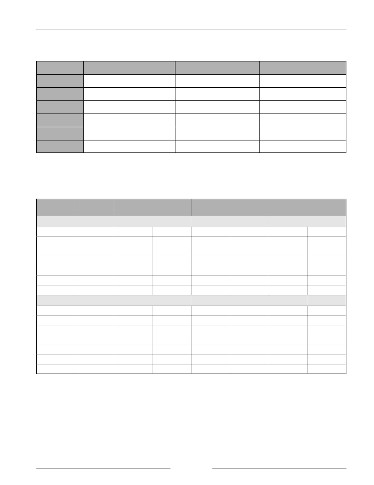
MACHINE COMPOSITION
CENTER SECTION
INNER WING
OUTER WING
8.2 m (27')
4.6 m (15')
-
1.8 m (6')
10.1 m (33')
4.6 m (15')
-
2.7 m (9')
11.9 m (39')
4.6 m (15')
-
3.7 m (12')
13.7 m (45')
4.6 m (15')
2.7 m (9')
1.8 m (6')
15.5 m (51')
4.6 m (15')
3.7 m (12')
1.8 m (6')
17.4 m (57')
4.6 m (15')
3.7 m (12')
2.7 m (9')
IMPLEMENT WEIGHT
Implement Weight in Kilograms and Pounds 7.2" Spacing
WIDTH
SHANKS
HOE/TRIP SHANK
350 POUND TRIPS
550 POUND TRIPS
(feet)
3 1/2" STEEL PRESS WHEELS
kg
lbs
kg
lbs
kg
lbs
27
45
7,030
15,498
8,724
19,233
8,826
19,458
33
55
8,004
17,645
9,909
21,845
10,033
22,120
39
65
8,987
19,812
11,260
24,823
11,407
25,148
45
75
11,200
24,691
13,953
30,760
14,123
31,135
51
85
11,973
26,395
15,011
33,093
15,204
33,518
57
95
12,957
28,566
16,220
35,760
16,436
36,235
3" RUBBER PRESS WHEELS
kg
lbs
kg
lbs
kg
lbs
27
45
7,135
15,731
8,865
19,543
8,967
19,768
33
55
8,115
17,891
10,058
22,174
10,183
22,449
39
65
9,132
20,132
11,463
25,271
11,610
25,596
45
75
11,373
25,073
14,187
31,278
14,358
31,653
51
85
12,238
26,981
15,277
33,679
15,469
34,104
57
95
13,254
29,221
16,518
36,415
16,733
36,890
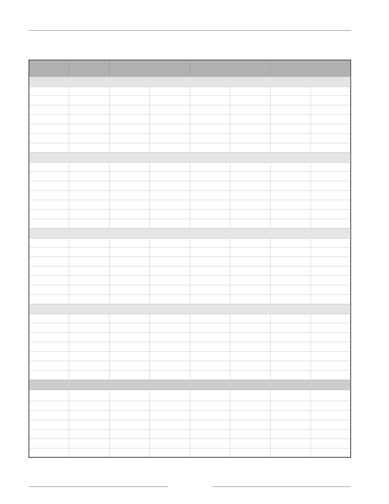
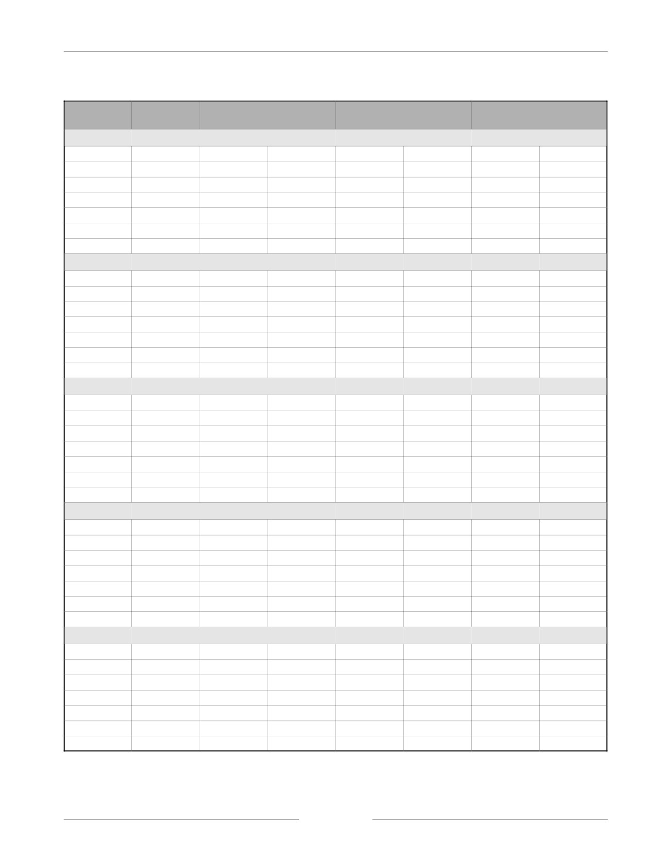
NOTE:
Weights listed do not include ground engaging tools or harrows.
page 1-21
SECTION 1 - GENERAL INFORMATION
Implement Weight in Kilograms and Pounds 10" Spacing
WIDTH
SHANKS
HOE/TRIP SHANK
350 POUND TRIPS
550 POUND TRIPS
(feet)
3 1/2" STEEL PRESS WHEELS
kg
lbs
kg
lbs
kg
lbs
27
34
7,212
15,900
8,107
17,873
8,184
18,043
33
40
8,142
17,950
9,036
19,920
9,126
20,120
39
48
9,097
20,055
10,298
22,704
10,407
22,944
45
56
11,406
25,146
12,882
28,400
13,009
28,680
51
62
12,193
26,881
13,706
30,216
13,846
30,526
57
70
13,164
29,022
14,790
32,606
14,949
32,956
4 1/2" STEEL PRESS WHEELS
kg
lbs
kg
lbs
kg
lbs
27
34
7,387
16,286
8,241
18,168
8,318
18,338
33
40
8,353
18,416
9,201
20,284
9,291
20,484
39
48
9,354
20,623
10,491
23,128
10,600
23,368
45
56
11,700
25,795
13,106
28,893
13,233
29,173
51
62
12,533
27,631
13,957
30,769
14,097
31,079
57
70
13,538
29,846
15,072
33,228
15,231
33,578
3" RUBBER PRESS WHEELS
kg
lbs
kg
lbs
kg
lbs
27
34
7,337
16,175
8,223
18,128
8,300
18,298
33
40
8,294
18,285
9,177
20,231
9,267
20,431
39
48
9,276
20,450
10,464
23,070
10,573
23,310
45
56
11,613
25,601
13,073
28,822
13,200
29,102
51
62
12,426
27,395
13,922
30,692
14,062
31,002
57
70
13,425
29,596
15,031
33,138
15,190
33,488
4" RUBBER PRESS WHEELS
kg
lbs
kg
lbs
kg
lbs
27
34
7,463
16,454
8,340
18,386
8,417
18,556
33
40
8,447
18,624
9,319
20,544
9,409
20,744
39
48
9,477
20,894
10,632
23,439
10,741
23,679
45
56
11,839
26,100
13,269
29,254
13,396
29,534
51
62
12,693
27,983
14,140
31,173
14,280
31,483
57
70
13,714
30,235
15,274
33,674
15,433
34,024
5 1/2" RUBBER PRESS WHEELS
kg
lbs
kg
lbs
kg
lbs
27
34
7,627
16,816
8,482
18,700
8,559
18,870
33
40
8,645
19,060
9,494
20,931
9,585
21,131
39
48
9,698
21,381
10,836
23,890
10,945
24,130
45
56
12,096
26,666
13,503
29,770
13,630
30,050
51
62
12,980
28,617
14,406
31,760
14,547
32,070
57
70
14,038
30,947
15,574
34,334
15,732
34,684
page 1-22
SECTION 1 - GENERAL INFORMATION
Implement Weight in Kilograms and Pounds 12" Spacing
WIDTH
SHANKS
HOE/TRIP SHANK
350 POUND TRIPS
550 POUND TRIPS
(feet)
3 1/2" STEEL PRESS WHEELS
kg
lbs
kg
lbs
kg
lbs
27
28
6,208
13,687
7,618
16,795
7,682
16,935
33
34
6,984
15,397
8,514
18,770
8,591
18,940
39
40
7,822
17,245
9,661
21,298
9,751
21,498
45
46
9,872
21,764
12,110
26,698
12,214
26,928
51
52
10,539
23,234
12,921
28,485
13,039
28,745
57
58
11,337
24,993
13,856
30,547
13,987
30,837
4 1/2" STEEL PRESS WHEELS
kg
lbs
kg
lbs
kg
lbs
27
28
6,305
13,900
7,722
17,023
7,785
17,163
33
34
7,103
15,659
8,633
19,032
8,710
19,202
39
40
7,961
17,551
9,815
21,638
9,906
21,838
45
46
10,033
22,118
12,271
27,052
12,375
27,282
51
52
10,719
23,632
13,111
28,905
13,229
29,165
57
58
11,539
25,440
14,059
30,994
14,190
31,284
3" RUBBER PRESS WHEELS
kg
lbs
kg
lbs
kg
lbs
27
28
6,293
13,874
7,693
16,960
7,756
17,100
33
34
7,088
15,626
8,618
18,999
8,695
19,169
39
40
7,945
17,515
9,783
21,568
9,874
21,768
45
46
10,013
22,075
12,251
27,009
12,355
27,239
51
52
10,699
23,587
13,077
28,829
13,195
29,089
57
58
11,516
25,388
14,035
30,942
14,167
31,232
4" RUBBER PRESS WHEELS
kg
lbs
kg
lbs
kg
lbs
27
28
6,378
14,061
7,778
17,147
7,841
17,287
33
34
7,192
15,855
8,722
19,228
8,799
19,398
39
40
8,068
17,786
9,906
21,839
9,997
22,039
45
46
10,155
22,388
12,393
27,322
12,497
27,552
51
52
10,859
23,941
13,237
29,183
13,355
29,443
57
58
11,695
25,784
14,215
31,338
14,346
31,628
5 1/2" RUBBER PRESS WHEELS
kg
lbs
kg
lbs
kg
lbs
27
28
6,935
15,288
7,881
17,374
7,944
17,514
33
34
7,318
16,134
8,848
19,507
8,925
19,677
39
40
8,215
18,111
10,053
22,164
10,144
22,364
45
46
10,326
22,765
12,564
27,699
12,668
27,929
51
52
11,052
24,365
13,430
29,607
13,547
29,867
57
58
11,911
26,260
14,431
31,814
14,562
32,104
page 1-23
SECTION 1 - GENERAL INFORMATION
OTHER SPECIFICATIONS
Spacing Configurations
4-Row
18.3, 25.4, or 30.5 cm (7.2, 10, or 12 inch) spacings
3-Row
25.4 or 30.5 cm (10 or 12 inch) spacings
Frame/Ground
71.1 to 81.3 cm (28 to 32 inches) depending on openers
Clearance
Cultivator-Style Trips
160 kg (350 lb) with 2.2 X 5.1 cm (7/8 X 2") shank, 4.4 cm (1 3/4") centers fit
47 degree sweeps
160 kg (350 lb) with 2.2 X 5.1 cm (7/8 X 2") shank, 5.7 cm (2 1/4") centers fit
50 degree sweeps
250 kg (550 lb) with 2.5 X 5.1 cm (1 X 2") shank, 4.8 cm (1 7/8") centers fit
47 degree sweeps
250 kg (550 lb) with 2.5 X 5.1 cm (1 X 2") shank, 5.7 cm (2 1/4") centers fit
50 degree sweeps
Adjustable Floating
1.9 X 5.1 cm (3/4 X 2") edge-on shank at bottom
Hoe-Style Shank/Opener
special openers required
four pressure settings, ranging from 27.2 to 104.3 kg (60 to 230 lb)
5.7 cm (2 1/4") hole centers
Press Wheels
Steel
8.9 X 55.9 cm (3 1/2 X 22")
11.4 X 55.9 cm (4 1/2 X 22")
Rubber
7.6 X 55.9 cm (3 X 22")
10.2 X 55.9 cm (4 X 22")
14 X 55.9 cm (5 1/2 X 22")
Options
shim kits to lower shanks behind tractor wheels.
single or dual endmarkers
press wheel mud scrapers
tow hitch for NH3 cart
bolt-on caps for steel press wheels
2-bar harrow for 3-row configuration
1-bar harrow for 4-row configuration
dual offset caster for the center section of 8.2 and 10.1 m (27 and 33 ft)
models
dual offset caster for the wing section (all models)
page 1-24