5000 AIR DRILL SERVICE MANUAL MODELS AD.A AND AD.B DR-015V2. SERVICE MANUAL
THIS SAFETY ALERT SYMBOL INDICATES IMPORTANT SAFETY
MESSAGES IN THIS MANUAL. WHEN YOU SEE THIS SYMBOL,
CAREFULLY READ THE MESSAGE THAT FOLLOWS AND BE
ALERT TO THE POSSIBILITY OF DEATH OR SERIOUS INJURY.
!
M171C
If Safety Decals on this machine use the words Danger, Warning or Caution,
which are defined as follows:
z DANGER: Indicates an immediate hazardous situation that, if not avoided, will
result in death or serious injury. The color associated with Danger is RED.
z WARNING: Indicates a potentially hazardous situation that, if not avoided,
could result in death or serious injury. The color associated with Warning is
ORANGE.
z CAUTION: Indicates an potentially hazardous situation that, if not avoided,
may result in minor or moderate injury. It may also be used to alert against
unsafe practices. The color associated with Caution is YELLOW.
If Safety Decals on this machine are ISO two panel Pictorial, decals are defined
as follows:
z The first panel indicates the nature of the hazard.
z The second panel indicates the appropriate avoidance of the hazard.
z Background color is YELLOW.
z Prohibition symbols such as
and
STOP
if used, are RED.
!
WARNING
IMPROPER OPERATION OF THIS MACHINE CAN CAUSE DEATH OR
SERIOUS INJURY. BEFORE USING THIS MACHINE, MAKE CERTAIN
THAT EVERY OPERATOR:
z Is instructed in safe and proper use of the machine.
z Reads and understands the Manual(s) pertaining to the machine.
z Reads and understands ALL Safety Decals on the machine.
z Clears the area of other persons.
z Learns and practices safe use of machine controls in a safe, clear area
before operating this machine on a job site.
It is your responsibility to observe pertinent laws and regulations and
follow CNH America LLC instructions on machine operation and
maintenance.
DR-015V2
Issued January, 2005
226
(Replaces All Previous Issues)
5000 AIR DRILL
SERVICE MANUAL
MODELS AD.A AND AD.B
DR-015V2
Starting Serial No. AD. A0000-K038301
AD. B0000- S068601
Y4S003001 - Y~
Ltd.
Canada:
CNH Canada Ltd.
1000 - 71 Street East
P.O. Box 1928
Saskatoon, Saskatchewan, Canada
S7K 3S5
Internet Website: http://www.flexicoil.com
The content of this book was based on the most current information available as of the
date of copyright. It is the policy of CNH Canada, Ltd., to improve and develop our
products continuously. We reserve the right to make changes or add improvements, at any
time, without incurring any obligation to make such changes on machines previously sold.
Printed in Canada
REPAIR PARTS
REPAIR PARTS IDENTIFICATION
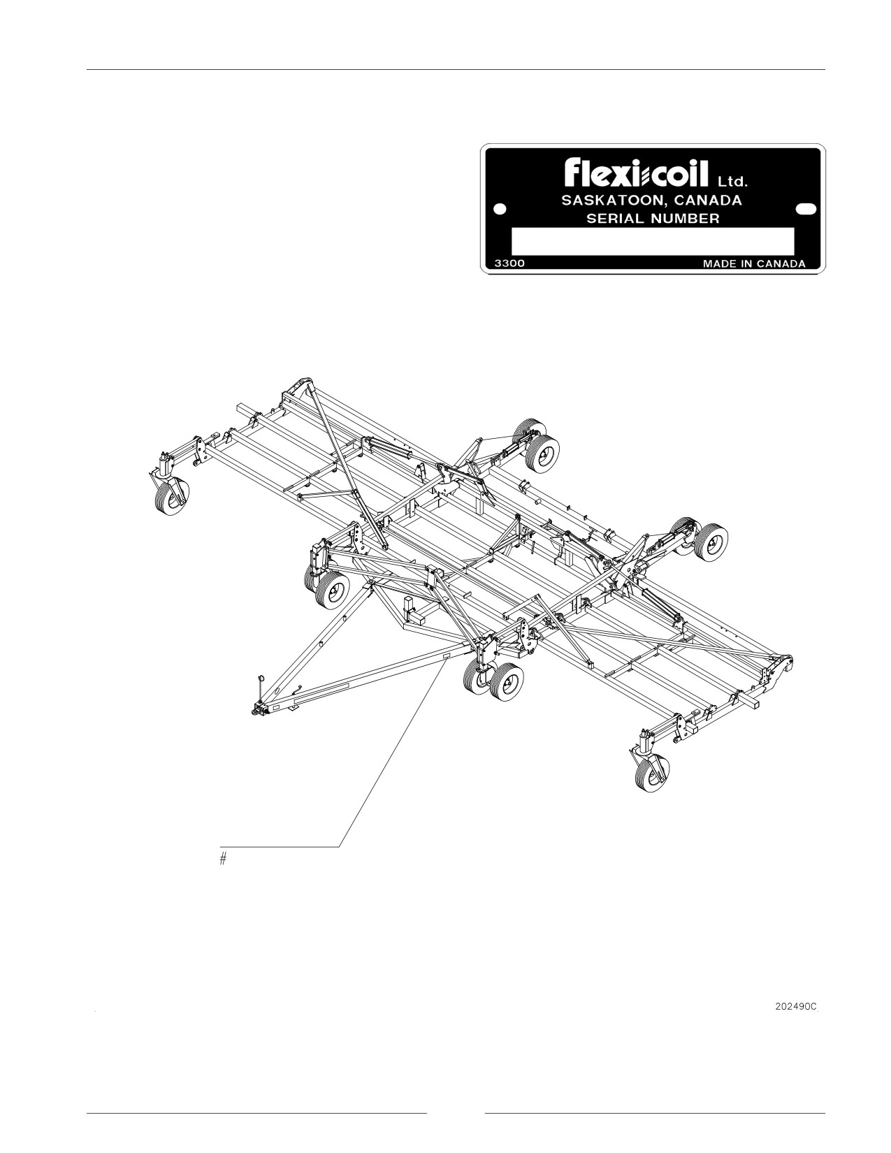
This Drill has a Serial Number plate attached to identify
the components installed on this machine. The plate looks
like the sample with a number stamped on.
For easy reference, locate the plate at the location shown
on the figure. Record the number on this sheet. When
requiring repair parts, take this number into your dealer.
This Serial Plate was used on machines manufactured to
June 2004.
i
REPAIR PARTS
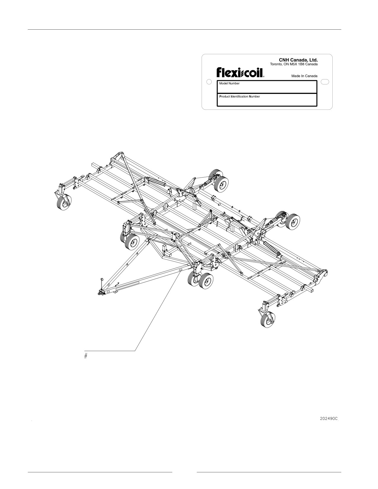
This implement has a Product Identification Number (PIN)
plate. The plate looks like the sample at right. For easy
reference, locate the PIN plate at the location shown on the
figure below. Record the number on this sheet. When
requiring repair parts, take this number into your dealer.
NOTE: This PIN plate replaces the Serial Number
plate found on machines manufactured prior to
June 2004.
ii
TABLE OF CONTENTS
Pages listed are a table of contents for that section
Section - Title
Page
1 - GENERAL INFORMATION
1-1
5 - ELECTRICAL
5-1
General Service Information
Connector Service Kit
Important Information
Remote Switch Installation
Service Tools
Safety
Units of Measure
6 - TRIPS, OPENERS, AND PRESS WHEEL
Bolt Torque Information
SERVICE
6-1
Machine Specifications
Service of Openers
Paint Touch-up Procedure
Service Guide for Offset Shank Locations
Press Wheels and Shanks
Ground Openers and Seed Boots
2 - ADJUSTMENTS
2-1
Troubleshooting Tables
Air Drill Leveling
Trip Compressor Tool Kit
Floating Hoe/Shank Adjustments
Tension Link Kit - 550 Pound Trip
Sweep Pitch Adjustments
Adjustment of Trip Assemblies
Trip/Shank Shim Installation
Heavy Duty Bearing Kits
3 - MECHANICAL SERVICE
3-1
Press Wheel Removal
Troubleshooting Tables
Packer Wheel Rest Assembly
Servicing Safety Precautions
Shank Spacing and Trip Release Pressure
General Operating Information
Trip Assemblies
Grease Locations
Sweep Pitch Adjustment
Maintenance
Trip Torque Specifications
Tire Pressures
Tire Pressures and hub and Spindle Details
Wheel Bolt Torque
7 - AIR SYSTEM
7-1
Heavy Caster Assembly
Troubleshooting Tables
Light Caster Assembly
Hoses
Caster Hub and Spindle Maintenance
Theory of Operation - Air System
Walking Beam Replacement
Determining Adequate Carrying Velocities
Wing Dual Caster Option
Header Assemblies
Dual Wing Caster Clamp
Hose Holder Brackets and Distribution Clamps
Auxiliary Tow Hitch
Caster Transport Lock Installation
Pin Guides
Depth Control Service
8 - ENDMARKER SERVICE
8-1
Walking Beam Carrier Spool Replacement
Endmarkers
Endmarker Replacement
Endmarker Hydraulics
4 - HYDRAULICS
4-1
Hydraulics
Replace Seals in Cylinders
Hydraulic Cylinders
INDEX
Depth Control
Wing Lift Hydraulics
iii
SECTION 1
GENERAL INFORMATION
CONTENTS OF THIS SECTION
Page
GENERAL SERVICE INFORMATION
1-3
IMPORTANT INFORMATION
1-4
SERVICE TOOLS
1-4
SAFETY
1-5
General Safety Practices
1-6
Servicing Safety Precautions
1-6
Safety During Operation
1-7
Air and Air Hoses
1-10
Hydraulics and Hydraulic Leaks
1-10
Shields
1-11
Electrical
1-11
Tires
1-11
Safety During Transport
1-12
Safety Decals
1-12
Transport Lighting Brackets
1-14
Transport Lighting Electrical Assembly
1-18
UNITS OF MEASURE
1-22
Abbreviations
1-22
Conversion Chart
1-23
BOLT TORQUE INFORMATION
1-24
MACHINE SPECIFICATIONS
1-26
Implement Dimensions
1-26
Implement Weight
1-27
Other Specifications
1-30
PAINT TOUCH-UP PROCEDURE
1-31
page 1-1
SECTION 1 - GENERAL INFORMATION
GENERAL SERVICE INFORMATION
NOTE: Read instructions carefully before you begin.
1. Be sure to read and follow all instructions to ensure
NOTE:
If you are assembling or servicing the
proper assembly, operation, and service of the
implement inside of a building, ensure the door
implement.
opening is large enough to allow the
implement to be removed after assembly.
2. Service may require the use of a forklift or other
Check the Specifications Tables in this section
suitable lifting device.
for the overall height and width in transport
position.
3. Implement must be serviced on a flat surface.
4. Left and right directions are determined from the rear
NOTE:
Additional bolt torque information can be
of the implement facing the forward direction of travel.
found later in this section.
5. Use a suitable sealant on hydraulic connections;
sealant paste is recommended. Be careful to prevent
sealant from entering the hydraulic system.
6. Apply a thread sealant to all female-to-male pipe
thread connections.
7. Do not allow tape to enter the hydraulic system.
8. Do not use a thread sealant on ORB or swivel fitting
connections.
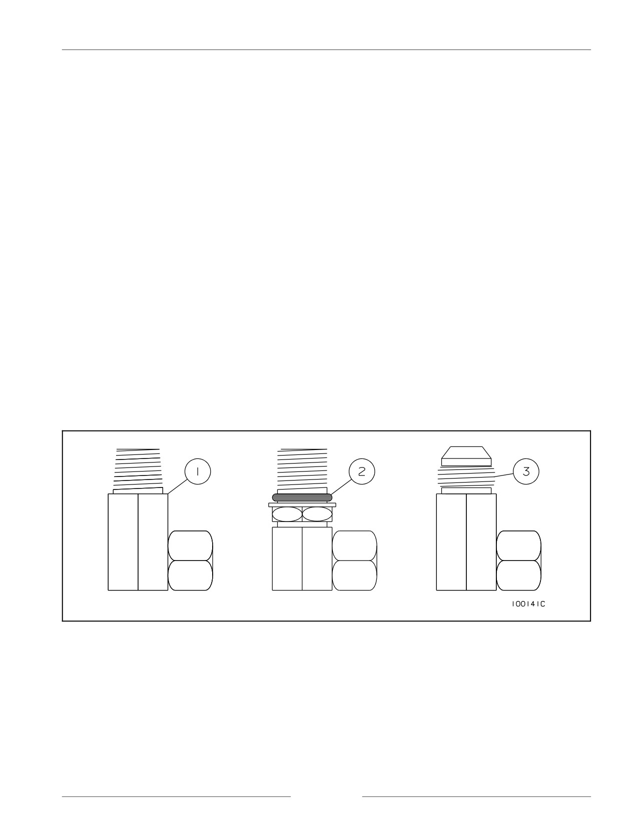
Hydraulic Fitting Identification
NOTE: Pipe thread fittings (1), O-ring boss fittings (2) and JIC fittings (3) may be the types of hydraulic fittings used.
page 1-3
SECTION 1 - GENERAL INFORMATION
IMPORTANT INFORMATION
All repair and maintenance work listed in this manual must be carried out only by qualified dealership personnel. Strictly
comply with all instructions given. Use only the specialized tools required.
Anyone who carries out the above operations without complying with the procedures shall be responsible for the subsequent
damages.
The manufacturer and all the organizations of its distribution chain, including (without limitation) national, regional, or local
dealers, reject any responsibility for damages due to the anomalous behavior of parts and/or components not approved by
the manufacturer itself. This includes those parts and/or components used for the servicing or repair of the product
manufactured or marketed by the manufacturer.
In any case, no warranty is given or attributed on the product manufactured or marketed by the manufacturer in case of
damages due to an anomalous behavior of parts and/or components not approved by the manufacturer.
The information in this manual is up to date at the date of the publication. It is the policy of the manufacturer to aim for
continuous improvement. Some information could not be updated due to modifications of a technical or commercial type,
as well as to suit the laws and regulations of different countries.
In case of disagreement, refer to your Sales and Service Networks.
SERVICE TOOLS
There are several service tools/update kits available through the parts department, for ease of servicing the air drill.
DR-900K
PIN GUIDES - (2) GUIDES FOR INSTALLING 1" AND 1.25" PINS.
DS-200K
KIT, PRESS WHEEL PULLER - PULLING TOOL.
DR-112K
KIT, TRANSPORT LOCK, 5000 SINGLE CASTER.
DR-114K
KIT, TRANSPORT LOCK, 5000 DUAL CASTER.
page 1-4
SECTION 1 - GENERAL INFORMATION
SAFETY
SAFETY - ALERT SYMBOL
This symbol is used to denote possible danger and care should be taken to prevent bodily injury. This symbol means
ATTENTION! BECOME ALERT! YOUR SAFETY IS INVOLVED!
THIS SYMBOL APPEARS WITH TEXT READING ìDANGER!î, ìCAUTION!î, OR ìWARNING!î THESE
WORDS INDICATE THREE LEVELS OF POSSIBLE HAZARDS; THEY ARE DESCRIBED BELOW.
DANGER!
Indicates an imminently hazardous situation that,
if not avoided, will result in death or serious injury.
The color associated with Danger is RED.
WARNING!
Indicates a potentially hazardous situation that, if
not avoided, could result in death or serious injury.
The color associated with Warning is ORANGE.
CAUTION! Indicates a potentially hazardous situation that, if
not avoided, may result in minor or moderate
injury. The color associated with Caution is
YELLOW.
page 1-5
SECTION 1 - GENERAL INFORMATION
GENERAL SAFETY PRACTICES
REVIEW this manual and operatorís manual before
NEVER transport Drill/cart combination with product in
servicing equipment.
tank.
NEVER allow anyone unfamiliar, untrained, or
MAINTAIN YOUR AIR DRILL in proper working
complacent to operate the air drill.
condition. Unauthorized modifications to the machine
may impair function and/or safety and affect machine life.
ALWAYS USE the jack supplied when unhooking the air
drill.
BE SURE the air drill is securely fastened to a large farm
tractor or an air cart that is attached to a large farm tractor
ALWAYS ensure weight of towing vehicle is heavier than
before operating hydraulics.
implement.
USE EXTREME CARE when making adjustments.
NEVER transport the air drill at speeds higher than 30
km/hr (18 mph).
KEEP CHILDREN AWAY from all farm equipment.
SERVICING SAFETY PRECAUTIONS
BLOCK the wheels to prevent movement when servicing.
BE SURE the press wheels are blocked and wing lock pins
are in place before servicing or adjusting opener
assemblies or working on the air drill.
CAUTION!
The tractor engine should be stopped and the
wheels blocked to prevent any movement during
servicing.
Always be sure that the depth control safety lock
is in place when servicing the air drill.
Always be sure the wings are in field position
before servicing the air drill.
Escaping hydraulic fluid is a serious hazard.
Escaping hydraulic fluid that is under pressure can
penetrate the skin, causing serious injury. Relieve
pressure before disconnecting the hydraulic lines.
Check/tighten all connections before applying
pressure.
Never use your hand to search for leaks. Use a
piece of cardboard or paper. If any fluid is injected
into the skin, seek immediate medical attention.
Gangrene may result if the wound is not treated
within a few hours. Check your hydraulic fluid
containers for warnings concerning the hydraulic
fluids you use.
DO NOT walk within the radius of raised air drill
wings.
page 1-6
SECTION 1 - GENERAL INFORMATION
SAFETY DURING OPERATION
DO NOT ALLOW ANYONE ON THE AIR DRILL while
operating the air drill hydraulics.
NEVER disconnect the tractor from the air drill while the
air drill wings are raised.
KEEP CHILDREN AWAY from the air drill during
operation.
NEVER STAND within the radius of the raised wings.
Hydraulic or mechanical failure may result in rapid or
uncontrolled falling of the wings.
RAISE AND LOWER the wings only on level ground
with the depth control fully raised.
097002S
PARK ON LEVEL GROUND and block adequately
before servicing.
AVOID moving machines.
DO NOT sit or ride on moving implements. Death or
injury may result.
098001M1
DISENGAGE POWER AND SHUT DOWN the tractor
engine (remove the key from the tractor ignition), be
certain that all moving parts have stopped, and all pressure
in the system is relieved BEFORE cleaning, adjusting or
lubricating the air drill.
192169C
page 1-7
SECTION 1 - GENERAL INFORMATION
READ the operatorís manual thoroughly.
KEEP service area clean to prevent injury to service
technicians and others.
098002M1
DO NOT enter tight areas. Be aware of pinch zones prior
to commencing work.
BE CERTAIN machine is tagged ëout of orderí or work
area is supervised.
098003M1
BE CERTAIN all moving parts have stopped before
servicing.
098004M1
page 1-8
SECTION 1 - GENERAL INFORMATION
AVOID toxic vapors. Breathe clean air.
0960039S
DO NOT permit smoking.
196150S
WEAR protective clothing.
192078S
page 1-9
SECTION 1 - GENERAL INFORMATION
AIR AND AIR HOSES
COMPRESSOR HOSES may move unexpectedly when
suddenly disconnected.
098005M1
USE PROPER air nozzles. Do not use compressed air to
clean clothes or direct it toward any part of yourself.
098006M1
AVOID getting chemicals into eyes. Use eye protection.
098007M1
HYDRAULICS AND HYDRAULIC LEAKS
AVOID high-pressure fluids.
ESCAPING HYDRAULIC FLUID IS A SERIOUS
HAZARD. Escaping hydraulic fluid under pressure can
penetrate the skin causing serious injury. Relieve pressure
before disconnecting the hydraulic lines. Check/tighten
all connections BEFORE applying pressure.
BEWARE excessive hydraulic pressure. Explosive
structural failure can result.
BEWARE air locks in cylinders. Large cylinder
000002C
displacements can occur without hydraulic oil flow.
page 1-10
SECTION 1 - GENERAL INFORMATION
SHIELDS
REPAIR damaged shields.
KEEP all shields in place.
BE EXTRA CAUTIOUS when repairing or servicing
without protective shields.
098008M1
ELECTRICAL
REMOVE the ground wire to avoid arcing contacts.
REMOVE GROUND WIRE when welding.
098009M1
TIRES
USE A CAGE IF POSSIBLE when setting tires on rims.
AVOID excessive air pressure.
DO NOT OVER-INFLATE TIRES. NEVER lean over a
tire while inflating it.
0960041S
page 1-11
SECTION 1 - GENERAL INFORMATION
SAFETY DURING TRANSPORT
CHECK with local authorities regarding transport on
BE SURE all the wheel bolts are torqued to proper
public roads. Obey all applicable laws and regulations.
specifications before transporting the air drill.
ONLY TOW at a safe speed (30 km/hr/18 mph). Use
WATCH for power poles and overhead power lines.
caution when turning corners or meeting traffic.
ALWAYS lock the tractor drawbar when transporting the
BE SURE transport lighting is plugged in and that the red
air drill.
taillight(s), amber flashers, and amber signal lights are all
working properly.
ALWAYS park the air drill on level ground and block the
wheels before unhooking from the towing vehicle.
ALWAYS be certain that no one is behind or near the air
drill before moving it.
NEVER subject the air drill to steep side grades while in
transport position.
BE SURE all safety transport locks are in place before
transporting the air drill.
ALWAYS use the hitch jack supplied with the air drill
when unhooking from the tractor.
BE SURE the reflector decals are clearly visible from all
sides of the air drill and the ëSlow Moving Vehicleí sign
NEVER brake or decelerate during cornering.
is at the rear of the air drill in clear view of overtaking
traffic.
ALWAYS enter corners slowly. SLOW the machine to
turning speed before entering a corner. DO NOT
BE SURE the tractor weight is equal to or greater than the
decelerate while executing the turn.
total weight of the air cart and air drill.
SAFETY DECALS
KEEP SAFETY DECALS CLEAN. Wipe clean when
To replace decals:
necessary.
1. Remove the old decal. Clean the area where the new
CHECK that the safety decals are not obstructed by the
decal will be affixed.
openers. If the decals are covered up, replace in a location
that is clear to view.
2. Remove the decal backing. Carefully affix the decal
to the air drill.
REPLACE missing or unreadable decals. New decals are
available from your dealer.
3. Work the air bubbles out from under the decal. Use a
clean piece of paper or the decal backing itself.
page 1-12
SECTION 1 - GENERAL INFORMATION
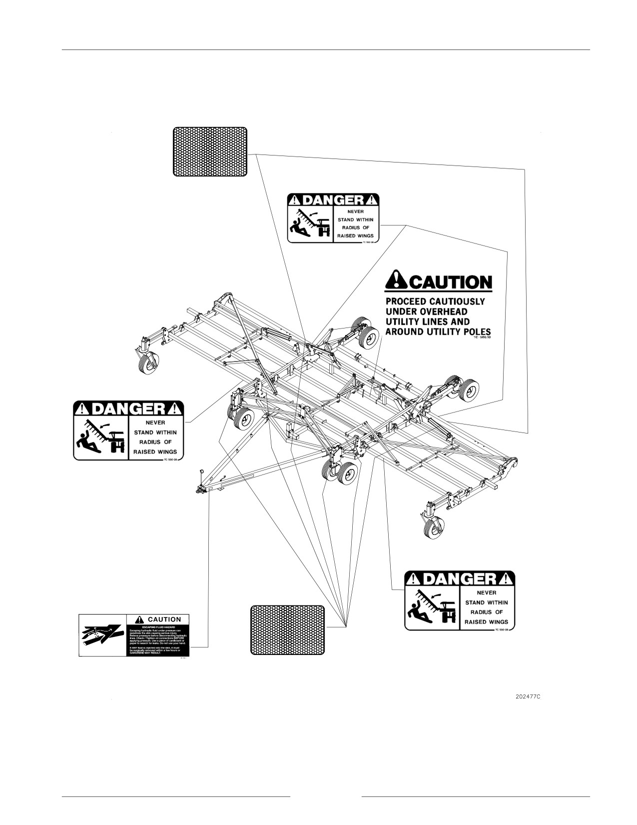
DECAL LOCATIONS
6027
GD-500.77
GD-500.77
GD-500.77
GD-500.77
6026
GD-500.77
page 1-13

SECTION 1 - GENERAL INFORMATION
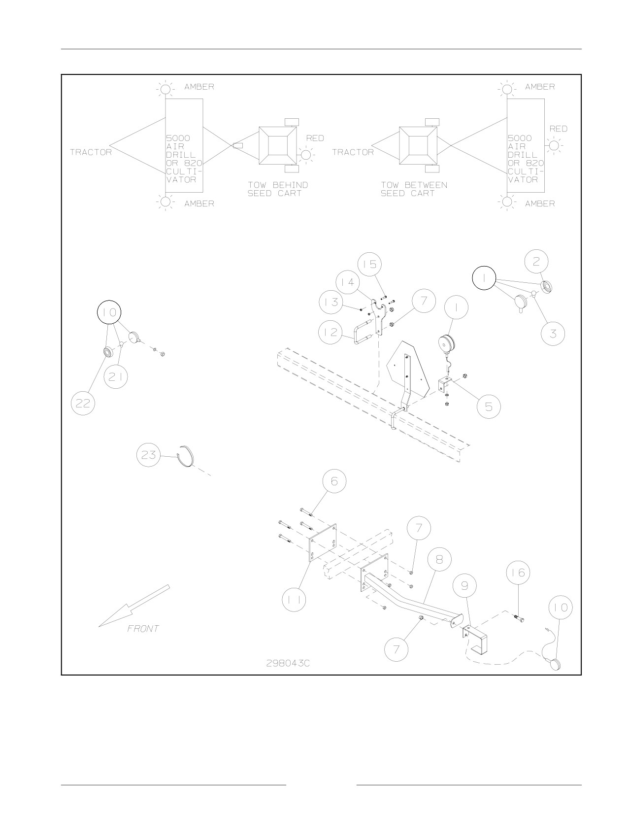
TRANSPORT LIGHTING ASSEMBLY
First Serial Range: AD.A0000-K039601 to AD.A0000-S068500
REF
DESCRIPTION
REF
DESCRIPTION
1
TAIL LIGHT ASSEMBLY, RED
11
BACKING PLATE, UNIVERSAL
2
LENS, RED
12
U-BOLT SQ .5" X 4.125" W X 5.25" D
3
BULB, DOUBLE CONTACT
13
LOCKNUT .313" UNC
5
MOUNT BRACKET, RED LIGHT
14
BRACKET, PLUG RECEPTACLE
6
BOLT .5 X 3.5 GR. 5
15
BOLT .313 X 1.5 GR. 5
6
BOLT .5 X 5.5 GR. 5
16
BOLT .5 X 1 GR.5
6
BOLT .5 X 7.5 GR. 5
21
BULB, SINGLE CONTACT
7
LOCKNUT .5" UNC
22
LENS, AMBER
8
BRACKET, AMBER LIGHT
23
CABLE TIE STRAP 21"
9
SHIELD, AMBER SAFETY LIGHT
23
CABLE TIE STRAP 14"
10
LIGHT ASSEMBLY, WARNING - AMBER
Transport Lighting Assembly - 5000 Air Drill Parts
page 1-14
SECTION 1 - GENERAL INFORMATION
Transport Lighting Assembly - First Serial Range
page 1-15

SECTION 1 - GENERAL INFORMATION
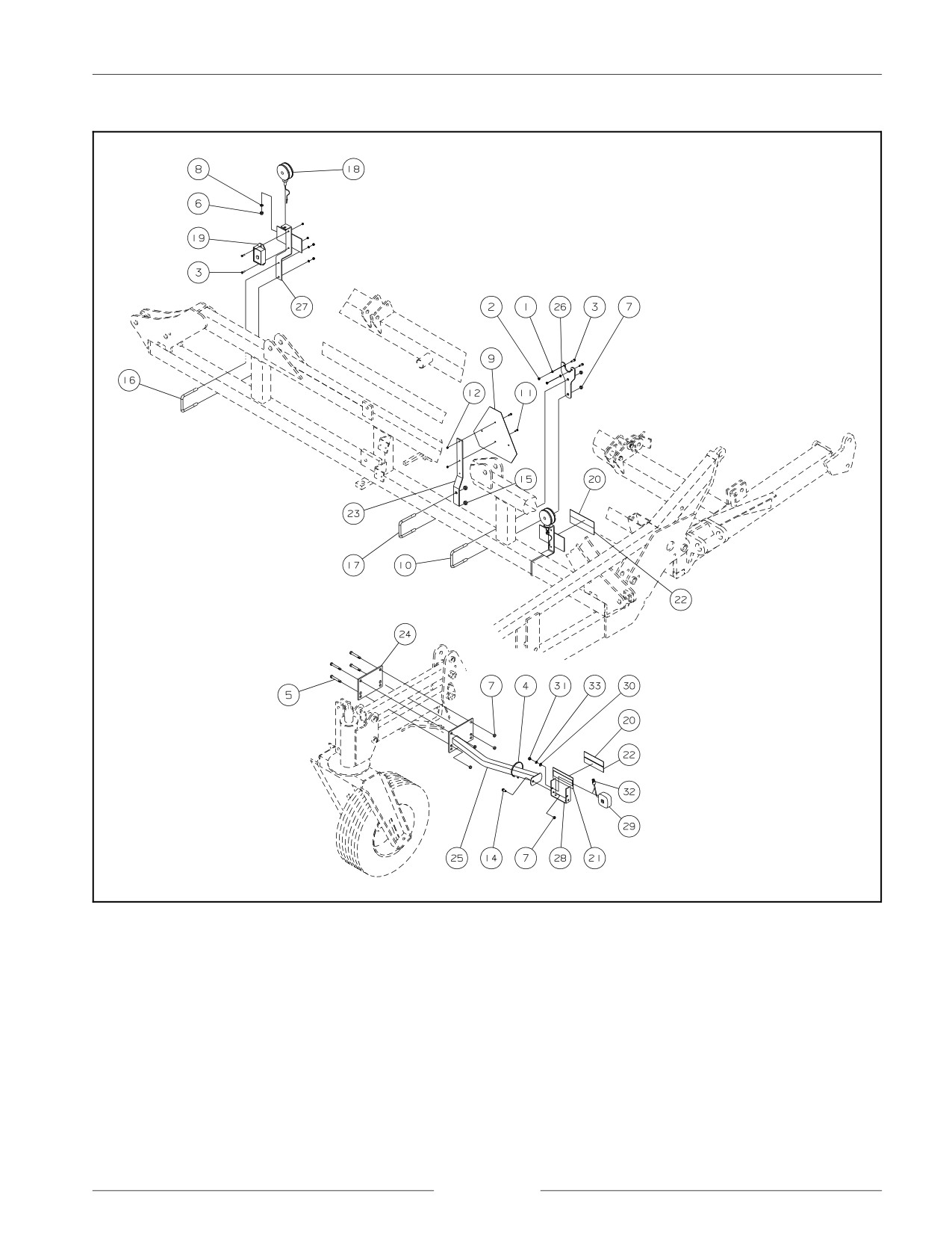
TRANSPORT LIGHTING ASSEMBLY
Second Serial Range: AD.B0000-S068601 to AD.B0000-U094935
AD-097701 to AD-110657
Y4S003001 to Y~
REF
DESCRIPTION
REF
DESCRIPTION
1
WASHER, LOCK .313 YZD
18
LIGHT, RED
2
NUT .313" UNC
18
BULB, DOUBLE CONTACT
3
BOLT .313 X 1.5 UNC GR5 YZD
19
MODULE, IMPLEMENT LIGHTING
CONTROL
4
STRAP, CABLE 14"
20
DECAL - RETROREFLECTIVE RED 2.0 X
9.0
5
BOLT .5 X 7.5 UNC GR5 YZD
21
DECAL - RETROREFLECTIVE AMBER 2.0
X 9.0
6
NUT .5" UNC
22
DECAL - FLUORESCENT RED ORANGE
7
NUT, LOCK .5" UNC
23
BRACKET, S.M.V. SIGN
8
WASHER, LOCK .5 YZD
24
PLATE, BACKING, UNIVERSAL
9
SIGN, WARNING, S.M.V.
25
BRACKET, AMBER LIGHT
10
U-BOLT, US .5 4.125W 5.25D
26
BRACKET, PLUG RECEPTACLE
11
BOLT .25 X .75 UNC GR5 YZD
27
BRACKET, MOUNT RED LIGHT/DECAL
12
NUT, LOCK .25" UNC
28
BRACKET, AMBER LIGHT / DECAL MOUNT
13
BOLT .313 X 1 UNC GR5 YZD
29
LIGHT ASSEMBLY, WARNING - AMBER
14
BOLT .5 X 1 UNC GR5 YZD
29
LIGHT, AMBER
15
NUT, LOCK .625" UNC
29
BULB, SINGLE CONTACT
16
U-BOLT, US .313 4.125W 4.75D UNC GR2
30
WASHER .531 X 1.062 X .095
YZD
17
U-BOLT, US .625 4.063W 5.375D UNC GR5
31
NUT .5 UNF GR5 YZD
YZD
18
LIGHT, STOP, ASSEMBLY, TAIL/SIGNAL
32
CONNECTOR, ELEC, PLASTIC2C
RECEPTACLE
18
LIGHT, RED
33
WASHER, LOCK .5 YZD
Transport Lighting Assembly - Second Serial Range
page 1-16
SECTION 1 - GENERAL INFORMATION
Transport Lighting Assembly - Second Serial Range
page 1-17
SECTION 1 - GENERAL INFORMATION
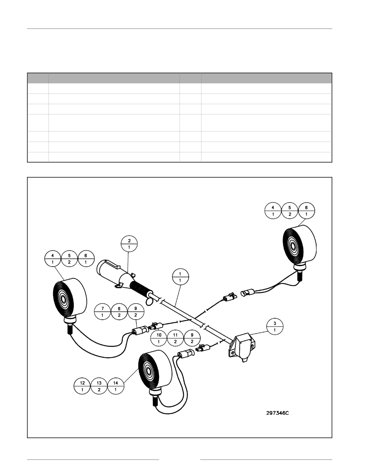
SAFETY LIGHTING ELECTRICAL ASSEMBLY
First Serial Range: AD.A0000-K039601 to AD.A0000-S068500
REF
DESCRIPTION
REF
DESCRIPTION
1
CABLE HARNESS, LIGHTING -TILLAGE
8
CONTACT PIN, ELECTRICAL CONNECTOR
2
ELECTRICAL PLUG, 7 POLE
9
SEAL, ELECTRICAL CONNECTOR
3
ELECTRICAL SOCKET, 7 POLE
10
PLUG CAB, ELECTRICAL CONNECTOR
4
LIGHT ASSEMBLY, WARNING - AMBER
11
CONTACT SOCKET, ELECTRICAL
CONNECTOR
5
LENS, AMBER
12
TAIL LIGHT ASSEMBLY, RED
6
BULB, SINGLE CONTACT
13
LENS, RED
7
PLUG CAB, ELECTRICAL CONNECTOR
14
BULB, DOUBLE CONTACT
Safety Lighting Electrical Assembly - 5000 Air Drill Parts
Safety Lighting Assembly
page 1-18
SECTION 1 - GENERAL INFORMATION
page 1-19

SECTION 1 - GENERAL INFORMATION
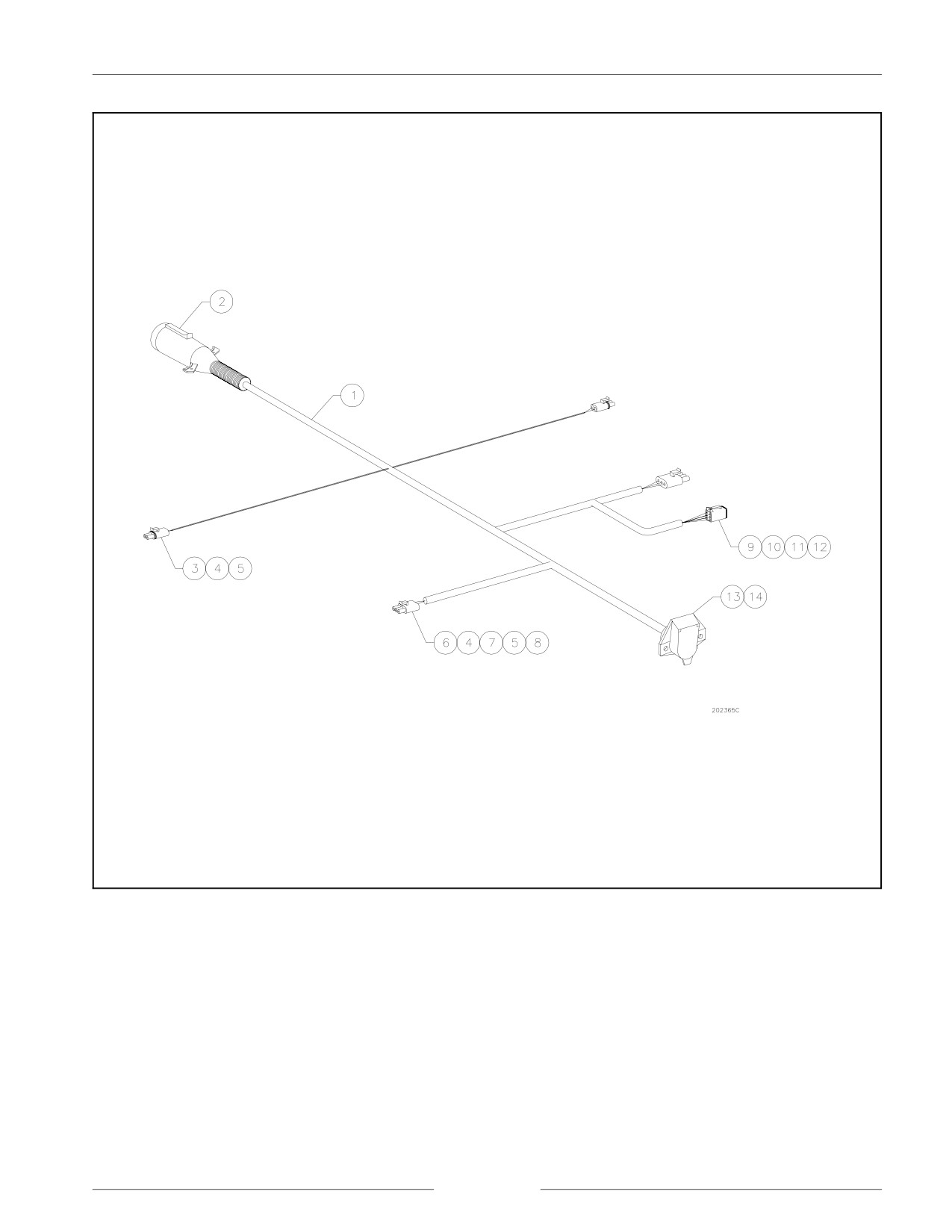
SAFETY LIGHTING ELECTRICAL ASSEMBLY
Second Serial Range: AD.B0000-S068601 to AD.B0000-U094935
AD-097701 to AD-110657
Y4S003001 to Y~
REF
DESCRIPTION
1
HARNESS, LIGHTING TILLAGE
2
CONNECTOR, ELEC METAL 7C PLUG C/W CABLE PROTECTOR
3
CONNECTOR, ELEC, PLASTIC 2C PLUG
4
SOCKET, CONTACT 14-16AWG BRASS TIN PLATED
5
SEAL, ELECTRICAL CONNECTOR
6
CONNECTOR, ELEC, PLASTIC 3C PLUG
7
SOCKET, CONTACT 18-20AWG BRASS TIN PLATED
8
SEAL, CONNECTOR GREEN
9
CONNECTOR, ELEC, PLASTIC 6C PLUG
10
CONNECTOR, ELEC, LOCK, 6C PLUG DT
11
SOCKET, CONTACT 16-18AWG COPPER NICKEL PLATED
12
SOCKET, CONTACT 14-16AWG COPPER NICKEL PLATED
13
CONNECTOR, ELEC METAL 7C RECEPTACLE
14
COVER, RUBBER BOOT
100
CLAMP, CABLE - .75" ID
Safety Lighting Electrical Assembly - Second Serial Range
page 1-20
SECTION 1 - GENERAL INFORMATION
Safety Lighting Assembly - Second Serial Range
page 1-21
SECTION 1 - GENERAL INFORMATION
UNITS OF MEASURE
ABBREVIATIONS
Acres
ac
Kilometers per hour
km/hr
Atmospheres
atm
Kilopascal
kPa
Bushel
bu
Kilowatt
kW
Centimeters
cm
Liters per hectare
L/ha
Cubic Meters
m3
Liters per minute
L/min
Cubic Feet
ft3
Liters
L
Degrees Fahrenheit
F/
Meters
m or M
Degrees Celsius
C/
Miles per hour
mph
Feet
ft
Milliliters
mL
Fluid ounces
oz
Millimeters
mm
Gallons per minute
gal/m
Newton Meters
N"m
Gallons per acre
gal/ac
Ounces
oz
Gallons
gal
Pound force inches
lbf"in
Hectares
ha
Pound force feet
lbf"ft
Horsepower
hp
Pounds per square inch
PSI
Inch
in
Pounds
lbs
Kilograms per hectare
kg/ha
Pounds per acre
lbs/ac
Kilograms
kg
Ton (short)
t
Kilometer
km
Tonne
t
page 1-22