New Holland 300FP / 380FP Header. SERVICE MANUAL (2016)
SERVICE MANUAL
300FP / 380FP
Header
Part number 47998488
English
February 2016
SERVICE MANUAL
300FP Auger with high performance fingers, 300FP Auger with high
performance paddles, 300FP Auger with standard paddles, 380FP Auger with
high performance fingers, 380FP Auger with high performance paddles,
380FP Auger with standard paddles
47998488 17/03/2016
EN
Contents
INTRODUCTION
Hydraulic systems
35
[35.000] Hydraulic systems
35.1
[35.359] Main control valve
35.2
[35.560] Pickup lift circuit
35.3
[35.661] Grass pickup drive system
35.4
Electrical systems
55
[55.000] Electrical system
55.1
[55.100] Harnesses and connectors
55.2
Attachments/Headers
58
[58.120] Attachment/Header feed auger
58.1
[58.900] Belt feeding
58.2
Product feeding
60
[60.220] Pickup
60.1
4799848817/03/2016
INTRODUCTION
47998488 17/03/2016
1
Contents
INTRODUCTION
Basic instructions - How to use and navigate through this Manual (*)
3
Foreword - Important notice regarding equipment servicing (*)
10
Safety rules (*)
11
Safety rules - Ecology and the environment (*)
12
Safety rules (*)
13
Personal safety (*)
16
Basic instructions - Shop and assembly (*)
17
Torque (*)
19
Torque - Standard torque data for hydraulic connections (*)
22
Basic instructions - Chain Wear Tables - Roller Chains (*)
29
Conversion factors (*)
31
Product identification (*)
32
Product identification - Machine orientation (*)
33
(*) See content for specific models
47998488 17/03/2016
2
INTRODUCTION
Basic instructions - How to use and navigate through this Manual
300FP
ANZ --- APAC --- LA --- MEA --- WE
380FP
ANZ --- APAC --- LA --- MEA --- WE
Technical information
This manual has been produced by a new technical information system. This new system is designed to deliver
technical information electronically through Web delivery (eTim), DVD and in paper manuals. A coding system called
SAP has been developed to link the technical information to other Product Support functions, e.g., Warranty.
Technical information is written to support the maintenance and service of the functions or systems on a customer's
machine. When a customer has a concern on his machine it is usually because a function or system on his machine
is not working at all, is not working efficiently, or is not responding correctly to his commands. When you refer to
the technical information in this manual to resolve that customer's concern, you will find all the information classified
using the SAP coding, according to the functions or systems on that machine. Once you have located the technical
information for that function or system then you will find all the mechanical, electrical or hydraulic devices, compo-
nents, assemblies and sub assemblies for that function or system. You will also find all the types of information that
have been written for that function or system, the technical data (specifications), the functional data (how it works),
the diagnostic data (fault codes and troubleshooting) and the service data (remove, install adjust, etc.).
By integrating SAP coding into technical information, you will be able to search and retrieve just the right piece of
technical information you need to resolve that customer's concern on his machine. This is made possible by attaching
3 categories to each piece of technical information during the authoring process.
The first category is the Location, the second category is the Information Type and the third category is the Product:
• LOCATION - is the component or function on the machine, that the piece of technical information is going to describe
e.g. Fuel tank.
• INFORMATION TYPE - is the piece of technical information that has been written for a particular component or
function on the machine e.g. Capacity would be a type of Technical Data that would describe the amount of fuel
held by the Fuel tank.
• PRODUCT - is the model for which the piece of technical information is written.
Every piece of technical information will have those 3 categories attached to it. You will be able to use any combination
of those categories to find the right piece of technical information you need to resolve that customer's concern on his
machine.
That information could be:
• the description of how to remove the cylinder head
• a table of specifications for a hydraulic pump
• a fault code
• a troubleshooting table
• a special tool
47998488 17/03/2016
3

INTRODUCTION
How to use this manual
This manual is divided into Sections. Each Section is then divided into Chapters. Contents pages are included at the
beginning of the manual, then inside every Section and inside every Chapter. An alphabetical Index is included at the
end of a Chapter. Page number references are included for every piece of technical information listed in the Chapter
Contents or Chapter Index.
Each Chapter is divided into four Information types:
• Technical Data (specifications) for all the mechanical, electrical or hydraulic devices, components and, assemblies.
• Functional Data (how it works) for all the mechanical, electrical or hydraulic devices, components and assemblies.
• Diagnostic Data (fault codes, electrical and hydraulic troubleshooting) for all the mechanical, electrical or hydraulic
devices, components and assemblies.
• Service Data (remove disassembly, assemble, install) for all the mechanical, electrical or hydraulic devices, com-
ponents and assemblies.
Sections
Sections are grouped according to the main functions or a systems on the machine. Each Section is identified by a
number 00, 35, 55, etc. The amount of Sections included in the manual will depend on the type and function of the
machine that the manual is written for. Each Section has a Contents page listed in alphabetic/numeric order.
This
table illustrates which Sections could be included in a manual for a particular product.
PRODUCT
Tractors
Vehicles with working arms: backhoes,
excavators, skid steers, ….
Combines, forage harvesters, balers, ….
Seeding, planting, floating, spraying
equipment, ….
SECTION
Mounted equipment and tools, ….
00 - Maintenance
05 - Machine completion and equipment
10 - Engine
14 - Main gearbox and drive
18 - Clutch
21 - Transmission
23 - Four wheel drive system
25 - Front axle system
27 - Rear axle system
29 - Hydrostatic drive
31 - Implement power take-off
33 - Brakes and controls
35 - Hydraulic systems
36 - Pneumatic system
37 - Hitches, drawbars and implement couplings
39 - Frames and ballasting
41 - Steering
44 - Wheels
46 - Steering clutches
48 - Tracks and track suspension
50 - Cab climate control
55 - Electrical systems
56 - Grape harvester shaking
58 - Attachments/headers
60 - Product feeding
61 - Metering system
62 - Pressing - Bale formation
47998488
17/03/2016
4

INTRODUCTION
63 - Chemical applicators
64 - Chopping
66 - Threshing
68 - Tying/Wrapping/Twisting
69 - Bale wagons
70 - Ejection
71 - Lubrication system
72 - Separation
73 - Residue handling
74 - Cleaning
75 - Soil preparation/Finishing
76 - Secondary cleaning / Destemmer
77 - Seeding
78 - Spraying
79 - Planting
80 - Crop storage / Unloading
82 - Front loader and bucket
83 - Telescopic single arm
84 - Booms, dippers and buckets
86 - Dozer blade and arm
88 - Accessories
89 - Tools
90 - Platform, cab, bodywork and decals
47998488 17/03/2016
5

INTRODUCTION
Section contents
Section
Number
Description
Maintenance
00
Machine completion and equipment
05
Engine
10
Main gearbox and drive
14
Clutch
18
Transmission
21
Four wheel drive system
23
Front axle system
25
Rear axle system
27
Hydrostatic drive
29
Implement power take-off
31
Brakes and controls
33
This Section covers the central parts of the hydraulic
system. The components that are dedicated to a
specific function are listed in the Chapter where all the
Hydraulic systems
35
technical information for that function is included.
This Section covers the pneumatic system. The
components that are dedicated to a specific function are
listed in the Chapter where all the technical information
Pneumatic system
36
for that function is included.
Hitches, drawbars and implement couplings
37
Frames and ballasting
39
Steering
41
Wheels
44
Steering clutches
46
Tracks and track suspension
48
Cab climate control
50
The Section covers the central parts of the electrical,
electronic, and lighting systems. The components that
are dedicated to a specific function are listed in the
Chapter where all the technical information for that
Electrical systems
55
function is included.
Grape harvester shaking
56
Attachments/headers
58
Product feeding
60
Metering system
61
Pressing - Bale formation
62
Chemical applicators
63
Chopping
64
Threshing
66
Tying/Wrapping/Twisting
68
Bale wagons
69
Ejection
70
Lubrication system
71
Separation
72
Residue handling
73
Cleaning
74
Soil preparation/Finishing
75
Secondary cleaning / Destemmer
76
Seeding
77
Spraying
78
Planting
79
Crop storage / Unloading
80
Front loader and bucket
82
47998488
17/03/2016
6
INTRODUCTION
Section
Number
Description
Telescopic single arm
83
Booms, dippers and buckets
84
Dozer blade and arm
86
Accessories
88
Tools
89
This Section covers all the main functions and systems
related to the body of the machine, including the
Platform, cab, bodywork and decals
90
operators cab and the platform.
47998488 17/03/2016
7
INTRODUCTION
Chapters
Each Chapter is identified by a number e.g. Hydraulic Systems - Main check valve- 35.359. The first number is
identical to the Section number i.e. Chapter 35.359 is inside Section 35, Hydraulic Systems. The second number is
representative of the Chapter contained within the Section.
CONTENTS
The Chapter Contents lists all the technical data (specifications), functional data (how it works), service data (remove,
install adjust, etc..) and diagnostic data (fault codes and troubleshooting) that have been written in that Chapter for
that function or system on the machine.
Contents
HYDRAULIC SYSTEMS - 35
Main control valve - 359
FUNCTIONAL DATA
Main control valve - Sectional view (35.359 - C.10.A.30)
TECHNICAL DATA
Main control valve - General specifications (35.359 - D.40.A.10)
SERVICE
Main control valve - Remove (35.359 - F.10.A.10)
INDEX
The Chapter Index lists in alphabetical order all the types of information (called Information Units) that have been
written in that Chapter for that function or system on the machine.
47998488 17/03/2016
8
INTRODUCTION
Information units and information search
Each chapter is composed of information units. Each information unit has a page reference within that Chapter. The
information units provide a quick and easy way to find just the right piece of technical information you are looking for.
Example information unit
Main control valve - Sectional View (35.359)
Information Unit SAP code
35
Hydraulic systems
SAP code classification
359
Main control valve
Page header and footer
The page header will contain the following references:
• Section and Chapter description
The page footer will contain the following references:
• Publication number for that Manual, Section or Chapter.
• Version reference for that publication.
• Publication date
• Section, chapter and page reference e.g.35.359 / 9
47998488 17/03/2016
9
INTRODUCTION
Foreword - Important notice regarding equipment servicing
300FP
ANZ --- APAC --- LA --- MEA --- WE
380FP
ANZ --- APAC --- LA --- MEA --- WE
All repair and maintenance work listed in this manual must be carried out only by qualified dealership personnel,
strictly complying with the instructions given, and using, whenever possible, the special tools.
Anyone who performs repair and maintenance operations without complying with the procedures provided herein
shall be responsible for any subsequent damages.
The manufacturer and all the organizations of its distribution chain, including - without limitation - national, regional, or
local dealers, reject any responsibility for damages caused by parts and/or components not approved by the manu-
facturer, including those used for the servicing or repair of the product manufactured or marketed by the manufacturer.
In any case, no warranty is given or attributed on the product manufactured or marketed by the manufacturer in case
of damages caused by parts and/or components not approved by the manufacturer.
The manufacturer reserves the right to make improvements in design and changes in specifications at any time without
notice and without incurring any obligation to install them on units previously sold. Specifications, descriptions, and
illustrative material herein are as accurate as known at time of publication but are subject to change without notice.
In case of questions, refer to your NEW HOLLAND Sales and Service Networks.
47998488 17/03/2016
10
INTRODUCTION
Safety rules
300FP
ANZ --- APAC --- LA --- MEA --- WE
380FP
ANZ --- APAC --- LA --- MEA --- WE
Personal safety
This is the safety alert symbol. It is used to alert you to potential personal injury hazards. Obey all
safety messages that follow this symbol to avoid possible death or injury.
Throughout this manual you will find the signal words DANGER, WARNING, and CAUTION followed by special in-
structions. These precautions are intended for the personal safety of you and those working with you.
Read and understand all the safety messages in this manual before you operate or service the machine.
DANGER indicates a hazardous situation that, if not avoided, will result in death or serious injury.
WARNING indicates a hazardous situation that, if not avoided, could result in death or serious injury.
CAUTION indicates a hazardous situation that, if not avoided, could result in minor or moderate injury.
FAILURE TO FOLLOW DANGER, WARNING, AND CAUTION MESSAGES COULD RESULT
IN DEATH OR SERIOUS INJURY.
Machine safety
NOTICE: Notice indicates a situation that, if not avoided, could result in machine or property damage.
Throughout this manual you will find the signal word Notice followed by special instructions to prevent machine or
property damage. The word Notice is used to address practices not related to personal safety.
Information
NOTE: Note indicates additional information that clarifies steps, procedures, or other information in this manual.
Throughout this manual you will find the word Note followed by additional information about a step, procedure, or
other information in the manual. The word Note is not intended to address personal safety or property damage.
47998488 17/03/2016
11
INTRODUCTION
Safety rules - Ecology and the environment
300FP
ANZ --- APAC --- LA --- MEA --- WE
380FP
ANZ --- APAC --- LA --- MEA --- WE
Soil, air, and water quality is important for all industries and life in general. When legislation does not yet rule the
treatment of some of the substances that advanced technology requires, sound judgment should govern the use and
disposal of products of a chemical and petrochemical nature.
Familiarize yourself with the relative legislation applicable to your country, and make sure that you understand this
legislation. Where no legislation exists, obtain information from suppliers of oils, filters, batteries, fuels, anti-freeze,
cleaning agents, etc., with regard to the effect of these substances on man and nature and how to safely store, use,
and dispose of these substances.
Helpful hints
• Avoid the use of cans or other inappropriate pressurized fuel delivery systems to fill tanks. Such delivery systems
may cause considerable spillage.
• In general, avoid skin contact with all fuels, oils, acids, solvents, etc. Most of these products contain substances
that may be harmful to your health.
• Modern oils contain additives. Do not burn contaminated fuels and or waste oils in ordinary heating systems.
• Avoid spillage when you drain fluids such as used engine coolant mixtures, engine oil, hydraulic fluid, brake fluid,
etc. Do not mix drained brake fluids or fuels with lubricants. Store all drained fluids safely until you can dispose of
the fluids in a proper way that complies with all local legislation and available resources.
• Do not allow coolant mixtures to get into the soil. Collect and dispose of coolant mixtures properly.
• The air-conditioning system contains gases that should not be released into the atmosphere. Consult an air-condi-
tioning specialist or use a special extractor to recharge the system properly.
• Repair any leaks or defects in the engine cooling system or hydraulic system immediately.
• Do not increase the pressure in a pressurized circuit as this may lead to a component failure.
• Protect hoses during welding. Penetrating weld splatter may burn a hole or weaken hoses, allowing the loss of oils,
coolant, etc.
Battery recycling
Batteries and electric accumulators contain several substances that can have a harmful
effect on the environment if the batteries are not properly recycled after use. Improper
disposal of batteries can contaminate the soil, groundwater, and waterways. NEW
HOLLAND strongly recommends that you return all used batteries to a NEW HOLLAND
dealer, who will dispose of the used batteries or recycle the used batteries properly. In
some countries, this is a legal requirement.
Mandatory battery recycling
NOTE: The following requirements are mandatory in Brazil.
Batteries are made of lead plates and a sulfuric acid solution. Because batteries contain heavy metals such as lead,
CONAMA Resolution 401/2008 requires you to return all used batteries to the battery dealer when you replace any
batteries. Do not dispose of batteries in your household garbage.
Points of sale are obliged to:
• Accept the return of your used batteries
• Store the returned batteries in a suitable location
• Send the returned batteries to the battery manufacturer for recycling
47998488 17/03/2016
12
INTRODUCTION
Safety rules
300FP
ANZ --- APAC --- LA --- MEA --- WE
380FP
ANZ --- APAC --- LA --- MEA --- WE
LEGAL OBLIGATIONS
This machine may be equipped with special guarding or other devices in compliance with local legislation. Some to
these require active use by the operator. Therefor, check local legislations on the usage of this machine.
ACCIDENT PREVENTION
Most accidents or injuries that occur in workshops are the result of non compliance to simple and fundamental safety
principles. For this reason, IN MOST CASES THESE ACCIDENTS CAN BE AVOIDED by applying the fundamental
safety principles, acting with the necessary caution and care.
Accidents may occur with all types of machine, regardless of how well the machine in question was designed and
built.
CAUTION
Unexpected machine movement!
1. Disengage all drives.
2. Engage parking brake.
3. Lower all attachments to the ground, or
raise and engage all safety locks.
4. Shut off engine.
5. Remove key from key switch.
6. Switch off battery key, if installed.
7. Wait for all machine movement to stop.
Failure to comply could result in minor or
moderate injury.
C0038A
SAFETY REQUIREMENTS FOR FLUID POWER SYSTEMS AND COMPONENTS - HY-
DRAULICS (EUROPEAN STANDARD EN982)
• Flexible hose assemblies must not be constructed from hoses which have been previously used as part of a hose
assembly.
• Do not weld hydraulic pipes: when flexible hoses or piping are damaged, replace them immediately.
• It is forbidden to modify a hydraulic accumulator by machining, welding or any other way.
• Before removing hydraulic accumulators for servicing, the liquid pressure in the accumulators must be reduced to
zero.
• Pressure check on hydraulic accumulators must be carried out by a method recommended by the accumulator
manufacturer.
• Take care not to exceed the maximum allowed pressure of the accumulator. After any check or adjustment, check
for leakages or gas in the hoses or tubes.
SAFETY RULES
General guidelines
• Carefully follow specified repair and maintenance procedures.
• When appropriate, use P.P.E (Personal Protective Equipment)
• Do not wear rings, wristwatches, jewellery, unbuttoned or loose articles of clothing such as: ties, torn clothing,
scarves, open jackets or shirts with open zips that may remain entangled in moving parts. It is advised to wear
approved safety clothing, e.g.: non-slip footwear, gloves, safety goggles, helmets, etc.
• Do not carry out repair operations with someone sitting in the driver's seat, unless the person is a trained technician
who is assisting with the operation in question.
• Do not operate the machine or use any of the implements from different positions, other than the driver's seat.
47998488 17/03/2016
13
INTRODUCTION
•
Do not carry out operations on the machine with the engine running, unless specifically indicated.
•
Bring all hydraulic cylinders to the home positions (down, retracted, etc.) before engine shut down.
•
Stop the engine and check that the hydraulic circuits are pressure-free before removing caps, covers, valves, etc.
•
All repair and maintenance operations must be carried out using extreme care and attention.
•
Service steps and platforms used in the workshop or elsewhere should be built according to the applicable stan-
dards and legislation.
•
Disconnect the Power Take-Off (PTO) and label the controls to indicate that the machine is being serviced.
•
Brakes are inoperative when manually released for repair or maintenance purposes. Use blocks or similar devices
to secure the machine in these conditions.
•
Only use specified towing points for towing the machine. Connect parts carefully. Make sure that all pins and/or
locks are secured in position before applying traction. Never remain near the towing bars, cables or chains that are
operating under load.
•
When loading or unloading the machine from the trailer (or other means of transport), select a flat area capable of
sustaining the trailer or truck wheels. Firmly secure the machine to the truck or trailer and lock the wheels in the
position used by the carrier.
•
Electric heaters, battery-chargers and similar equipment must only be powered by auxiliary power supplies with
efficient ground insulation to avoid electrical shock hazards.
•
Always use suitable hoisting or lifting devices when raising or moving heavy parts.
•
Keep bystanders away.
•
Never use gasoline, diesel oil or other inflammable liquids as cleaning agents. Use non-inflammable, non toxic
commercially available solvents.
•
Wear safety goggles with side guards when cleaning parts with compressed air.
•
Never use open flames for lighting when working on the machine or checking for leaks.
•
When carrying out checks with the engine running, request the assistance of an operator in the driver's seat. The
operator must maintain visual contact with the service technician at all times.
•
If operating outside the workshop, position the machine on a flat surface and lock in position. If working on a slope,
lock the machine in position. Move to a flat area as soon as is safely possible.
•
Maintenance and repair operations must be carried out in a clean and dry area. Clean up any water or oil spillage
immediately.
•
Do not create piles of oil or grease-soaked rags as they represent a serious fire hazard. Always store rags in a
closed metal container.
•
Before engaging the machine, make sure that there are no persons within the machine or implement range of action.
•
Empty your pockets of all objects that may fall accidentally unobserved into the machine inner compartments.
•
When metal parts are sticking out, use protective goggles or goggles with side guards, helmets, special footwear
and gloves.
•
When welding, use protective safety devices: tinted safety goggles, helmets, special overalls, gloves and footwear.
All persons present in the area where welding is taking place must wear tinted goggles. NEVER LOOK DIRECTLY
AT THE WELDING ARC WITHOUT SUITABLE EYE PROTECTION.
47998488 17/03/2016
14
INTRODUCTION
Machine start-up.
• Never run the engine in confined spaces that are not equipped with adequate ventilation for exhaust gas extraction.
• Never place the head, body, limbs, feet, hands or fingers near rotating and moving parts.
Hydraulic systems and fuel injection systems
• A liquid leaking from a tiny hole may be almost invisible but, at the same time, be powerful enough to penetrate
the skin. Therefore, NEVER USE HANDS TO CHECK FOR LEAKS but use a piece of cardboard or paper for this
purpose. If any liquid penetrates skin tissue, call for medical aid immediately. Failure to treat this condition with
correct medical procedure may result in serious infection or death.
• In order to check the pressure in the system use suitable instruments.
Wheels and tires
• Make sure that the tires are correctly inflated at the pressure specified by the manufacturer. Periodically check the
rims and tires for damage.
• Stand away from (at the side of) the tire when checking inflation pressure.
• Do not use parts of recovered wheels as incorrect welding brazing or heating may weaken and eventually cause
damage to the wheel.
• Never cut or weld a rim mounted with an inflated tire.
• Deflate the tire before removing any objects that may be jammed in the tire tread.
• Never inflate tires using inflammable gases, as this may result in explosions and injury to bystanders.
Removal and installation
• Lift and handle all heavy parts using suitable hoisting equipment. Make sure that parts are sustained by appropriate
hooks and slings. Use the hoisting eyebolts for lifting operations. Extra care should be taken if persons are present
near the load to be lifted.
• Handle all parts carefully. Do not put your hands or fingers between parts. Wear suitable safety clothing - safety
goggles, gloves and shoes.
• Avoid twisting chains or metal cables. Always wear safety gloves when handling cables or chains.
• Damaged or bent chains or cables are unreliable. Do not use them for lifting or towing. Always use suitable pro-
tective gloves when handling chains or cables.
• Chains should always be safely secured. Make sure that the hitch-up point is capable of sustaining the load in
question. Keep the area near the hitch-up point, chains or cables free of all bystanders.
• Metal cables tend to fray with repeated use. Always use suitable protective devices (gloves, goggles, etc.) when
handling cables.
47998488 17/03/2016
15
INTRODUCTION
Personal safety
300FP
ANZ --- APAC --- LA --- MEA --- WE
380FP
ANZ --- APAC --- LA --- MEA --- WE
WARNING
Heavy object!
ALWAYS use a hoist or get assistance to lift the component.
Failure to comply could result in death or serious injury.
W0086A
WARNING
Pressurized system!
Only use the bleed screw to bleed air from the fuel system. DO NOT loosen the fuel or injector lines
to bleed air. Injury or damage can occur. Fuel or injector lines are under very high pressure.
Failure to comply could result in death or serious injury.
W0285A
47998488 17/03/2016
16
INTRODUCTION
Basic instructions - Shop and assembly
300FP
ANZ --- APAC --- LA --- MEA --- WE
380FP
ANZ --- APAC --- LA --- MEA --- WE
Shimming
For each adjustment operation, select adjusting shims and measure the adjusting shims individually using a microm-
eter, then add up the recorded values. Do not rely on measuring the entire shimming set, which may be incorrect, or
the rated value shown on each shim.
Rotating shaft seals
For correct rotating shaft seal installation, proceed as follows:
1. Before assembly, allow the seal to soak in the oil it will be sealing for at least thirty minutes.
2. Thoroughly clean the shaft and check that the working surface on the shaft is not damaged.
3. Position the sealing lip facing the fluid.
NOTE: With hydrodynamic lips, take into consideration the shaft rotation direction and position the grooves so that
they will move the fluid towards the inner side of the seal.
4. Coat the sealing lip with a thin layer of lubricant (use oil rather than grease). Fill the gap between the sealing lip
and the dust lip on double lip seals with grease.
5. Insert the seal in its seat and press down using a flat punch or seal installation tool. Do not tap the seal with a
hammer or mallet.
6. While you insert the seal, check that the seal is perpendicular to the seat. When the seal settles, make sure that
the seal makes contact with the thrust element, if required.
7. To prevent damage to the seal lip on the shaft, position a protective guard during installation operations.
O-ring seals
Lubricate the O-ring seals before you insert them in the seats. This will prevent the O-ring seals from overturning and
twisting, which would jeopardize sealing efficiency.
Sealing compounds
Apply a sealing compound on the mating surfaces when specified by the procedure. Before you apply the sealing
compound, prepare the surfaces as directed by the product container.
Spare parts
Only use CNH Original Parts or NEW HOLLAND Original Parts.
Only genuine spare parts guarantee the same quality, duration, and safety as original parts, as they are the same
parts that are assembled during standard production. Only CNH Original Parts or NEW HOLLAND Original Parts can
offer this guarantee.
When ordering spare parts, always provide the following information:
• Machine model (commercial name) and Product Identification Number (PIN)
• Part number of the ordered part, which can be found in the parts catalog
47998488 17/03/2016
17
INTRODUCTION
Protecting the electronic and/or electrical systems during charging and welding
To avoid damage to the electronic and/or electrical systems, always observe the following practices:
1. Never make or break any of the charging circuit connections when the engine is running, including the battery
connections.
2. Never short any of the charging components to ground.
3. Always disconnect the ground cable from the battery before arc welding on the machine or on any machine
attachment.
• Position the welder ground clamp as close to the welding area as possible.
• If you weld in close proximity to a computer module, then you should remove the module from the machine.
• Never allow welding cables to lie on, near, or across any electrical wiring or electronic component while you
weld.
4. Always disconnect the negative cable from the battery when charging the battery in the machine with a battery
charger.
NOTICE: If you must weld on the unit, you must disconnect the battery ground cable from the machine battery.
The electronic monitoring system and charging system will be damaged if this is not done.
5. Remove the battery ground cable. Reconnect the cable when you complete welding.
WARNING
Battery acid causes burns. Batteries contain sulfuric acid.
Avoid contact with skin, eyes or clothing. Antidote (external): Flush with water. Antidote (eyes): flush
with water for 15 minutes and seek medical attention immediately. Antidote (internal): Drink large
quantities of water or milk. Do not induce vomiting. Seek medical attention immediately.
Failure to comply could result in death or serious injury.
W0111A
Special tools
The special tools that NEW HOLLAND suggests and illustrate in this manual have been specifically researched and
designed for use with NEW HOLLAND machines. The special tools are essential for reliable repair operations. The
special tools are accurately built and rigorously tested to offer efficient and long-lasting operation.
By using these tools, repair personnel will benefit from:
• Operating in optimal technical conditions
• Obtaining the best results
• Saving time and effort
• Working in safe conditions
47998488 17/03/2016
18
INTRODUCTION
Torque
300FP
ANZ --- APAC --- LA --- MEA --- WE
380FP
ANZ --- APAC --- LA --- MEA --- WE
Minimum hardware tightening torques (in N m or lb in /lb ft) for normal assembly applica-
tions unless otherwise stated
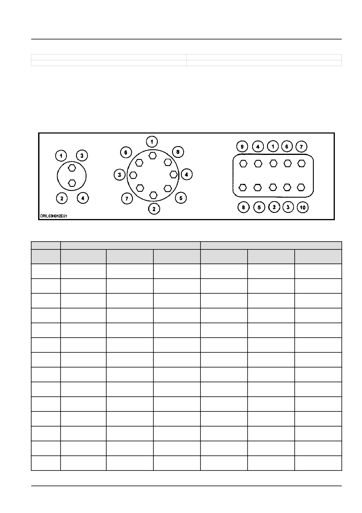
NOTICE: Shown below is the suggested initial torque tightening sequences for general applications, tighten in se-
quence from item 1 through to the last item of the hardware.
The minimum hardware tightening torque on drawings, in specifications etc. have priority.
The applicable CNH Standard is ENS7001.
DF5019-1
1
Metric hardware
Class 8.8 in N m (lb in or lb ft)
Class
10.9 in N m (lb in or lb ft)
Nominal
Plated nut
Lock nut
Hardened nut
Plated nut
Lock nut
Hardened nut
Size
M3
1.3 N·m
0.7 N·m
1.2 N·m
1.8 N·m
0.9 N·m
1.6 N·m
(11.5 lb in)
(6.2 lb in)
(10.6 lb in)
(15.9 lb in)
(8.0 lb in)
(14.2 lb in)
M4
2.9 N·m
1.6 N·m
2.6 N·m
4.2 N·m
2.3 N·m
3.7 N·m
(25.7 lb in)
(14.2 lb in)
(23.0 lb in)
(37.2 lb in)
(20.4 lb in)
(32.7 lb in)
M5
5.9 N·m
3.2 N·m
5.3 N·m
8.5 N·m
4.6 N·m
7.6 N·m
(52.2 lb in)
(28.3 lb in)
(46.9 lb in)
(75.2 lb in)
(40.7 lb in)
(67.3 lb in)
M6
10.1 N·m
5.5 N·m
9.1 N·m
14.5 N·m
7.9 N·m
13 N·m
(89.4 lb in)
(48.7 lb in)
(80.5 lb in)
(10.7 lb ft)
(69.9 lb in)
(9.6 lb ft)
M8
24.5 N·m
13.5 N·m
22 N·m
35.1 N·m
19.3 N·m
31.5 N·m
(18.1 lb ft)
(10.0 lb ft)
(16.2 lb ft)
(25.9 lb ft)
(14.2 lb ft)
(23.2 lb ft)
M10
48.7 N·m
26.8 N·m
43.8 N·m
69.5 N·m
38.2 N·m
62.5 N·m
(35.9 lb ft)
(19.8 lb ft)
(32.3 lb ft)
(51.3 lb ft)
(28.2 lb ft)
(46.1 lb ft)
M12
85 N·m
46.7 N·m
76.5 N·m
121 N·m
66.5 N·m
108.9 N·m
(62.7 lb ft)
(34.4 lb ft)
(56.4 lb ft)
(89.2 lb ft)
(49.0 lb ft)
(80.3 lb ft)
M14
135 N·m
74.2 N·m
121.5 N·m
193 N·m
106.1 N·m
173.7 N·m
(99.6 lb ft)
(54.7 lb ft)
(89.6 lb ft)
(142.3 lb ft)
(78.3 lb ft)
(128.1 lb ft)
M16
210 N·m
115.5 N·m
189 N·m
301 N·m
165.5 N·m
270.9 N·m
(154.9 lb ft)
(85.2 lb ft)
(139.4 lb ft)
(222 lb ft)
(122.1 lb ft)
(199.8 lb ft)
M18
299 N·m
164.4 N·m
269.1 N·m
414 N·m
227.7 N·m
372.6 N·m
(220.5 lb ft)
(121.3 lb ft)
(198.5 lb ft)
(305.4 lb ft)
(167.9 lb ft)
(274.8 lb ft)
M20
425 N·m
233.72 N·m
382.5 N·m
587 N·m
322.8 N·m
528.3 N·m
(313.5 lb ft)
(172.4 lb ft)
(282.1 lb ft)
(432.9 lb ft)
(238.1 lb ft)
(389.7 lb ft)
M22
579 N·m
318.4 N·m
521.1 N·m
801 N·m
440.5 N·m
720.9 N·m
(427 lb ft)
(234.8 lb ft)
(384.3 lb ft)
(590.8 lb ft)
(324.9 lb ft)
(531.7 lb ft)
M24
735 N·m
404.2 N·m
661.5 N·m
1016 N·m
558.8 N·m
914.4 N·m
(542.1 lb ft)
(298.1 lb ft)
(487.9 lb ft)
(749.4 lb ft)
(412.1 lb ft)
(674.4 lb ft)
M27
1073 N·m
590.1 N·m
967.5 N·m
1486 N·m
817.3 N·m
1337 N·m
(791.4 lb ft)
(435.2 lb ft)
(713.6 lb ft)
(1096 lb ft)
(602.8 lb ft)
(986.1 lb ft)
47998488 17/03/2016
19
INTRODUCTION
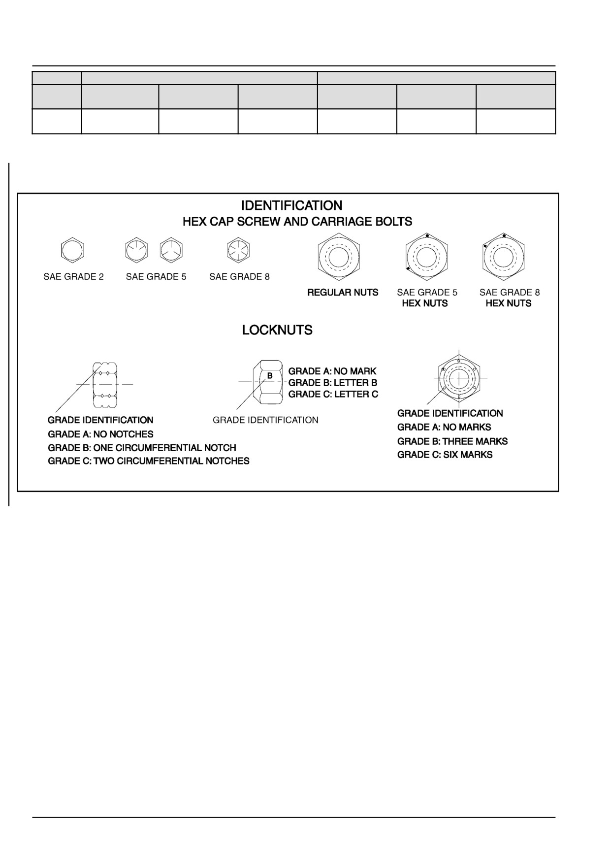
Class 8.8 in N m (lb in or lb ft)
Class 10.9 in N m (lb in or lb ft)
Nominal
Plated nut
Lock nut
Hardened nut
Plated nut
Lock nut
Hardened nut
Size
M30
1461 N·m
803.5 N·m
1315 N·m
2020 N·m
1111 N·m
1818 N·m
(1077.6 lb ft)
(592.6 lb ft)
(969.9 lb ft)
(1489.9 lb ft)
(819.4 lb ft)
(1340.9 lb ft)
47998488 17/03/2016
20
47998488 17/03/2016
21
INTRODUCTION
Torque - Standard torque data for hydraulic connections
300FP
ANZ --- APAC --- LA --- MEA --- WE
380FP
ANZ --- APAC --- LA --- MEA --- WE
General information
• Hydraulic connections require a minimum assembly torque in order to provide zero leakage at rated pressure with
adequate fatigue resistance. Over-torquing of a hydraulic connection can also lead to leakage or failure. For some
connections, NEW HOLLAND requires a different torque value than is listed in the ISO and SAE standards.
• The torque values in this document should be used whenever possible or applicable.
NOTICE: Always follow the instructions in this manual for specific torque values when you service components.
The information in this section is for general guidance only when a procedure contains no specific torque value.
Tolerance
• The tolerance for all torque values is ± 10 %. This tolerance must include all assembly variation, not only the torque
wrench repeatability.
Lubrication
Application of grease or other lubricants to hydraulic connectors should be avoided. If clean hydraulic oil is already
on the connection, it is not required to remove the oil. Generally, application of grease:
• May cause a significant change in the torque required to properly tighten the connection.
• May reduce the connection’s resistance to vibration.
• Excessive grease may displace an elastomer seal during tightening.
• Grease extrusion when connection is tightened may be mistaken for leakage.
NEW HOLLAND products generally use O-Ring Boss (ORB) connectors that have Teflon™-coated O-rings, eliminat-
ing the need for O-ring lubrication during installation. For connections which are made into aluminum manifolds or
with stainless steel connectors, it may be required to apply a lubricant to prevent galling.
Use of LOCTITE® and other thread-locking compounds is prohibited. These compounds:
• May cause a significant change in the torque required to properly tighten the connections.
• Reduce the serviceability of the joint.
• May prevent the O-ring from properly sealing if the compound gets on the O-ring.
47998488 17/03/2016
22

INTRODUCTION
Torque values for metric O-Ring Boss (ORB) port connections
S-Series *
L-Series **
Metric
Ferrous
Non-Ferrous
Ferrous
Non-Ferrous
thread
N·m (lb ft) ± 10 %
N·m (lb ft) ± 10 %
N·m (lb ft) ± 10 %
N·m (lb ft) ± 10
%
M8 x 1
10.5
(7.7)
6.3
(4.6)
8.5
(6.3)
5
(3.7)
M10 x 1
21
(15.5)
12.5
(9.2)
15.5
(11.4)
9.3
(6.9)
M12 x 1.5
37
(27.3)
22
(16.2)
27
(19.9)
16
(11.8)
M14 x 1.5
47
(34.7)
28
(20.7)
37
(27.3)
22
(16.2)
M16 x 1.5
58
(42.8)
35
(25.8)
42
(31)
25
(18.4)
M18 x 1.5
74
(54.6)
44
(32.5)
47
(34.7)
28
(20.7)
M22 x 1.5
105
(77.4)
63
(46.5)
63
(46.5)
38
(28)
M27 x 2
178
(131.3)
107
(78.9)
105
(77.4)
63
(46.5)
M30 x 2
225
(166)
135
(99.6)
136
(100.3)
82
(60.5)
M33 x 2
325
(239.7)
195
(143.8)
168
(123.9)
101
(74.5)
M42 x 2
345
(254.5)
207
(152.7)
220
(162.3)
132
(97.4)
M48 x 2
440
(324.5)
264
(194.7)
273
(201.4)
164
(121)
M60 x 2
525
(387.2)
315
(232.3)
330
(243.4)
198
(146)
* S-Series connectors are used with O-Ring Face Seals (ORFS).
** L-Series connectors are used with 37 ° flare.
Torque values for metric O-Ring Boss (ORB) port plugs
Ferrous
Non-ferrous
Metric
Internal hex
External hex
N·m (lb ft) ± 10 %
thread
N·m (lb ft) ± 10 %
N·m (lb ft) ± 10 %
M8 x 1
8.5
(6.3)
10.5
(7.7)
6.3
(4.6)
M10 x 1
16
(11.8)
21
(15.5)
12.5
(9.2)
M12 x 1.5
23
(17)
37
(27.3)
22
(16.2)
M14 x 1.5
47
(34.7)
47
(34.7)
28
(20.7)
M16 x 1.5
58
(42.8)
58
(42.8)
35
(25.8)
M18 x 1.5
74
(54.6)
74
(54.6)
44
(32.5)
M22 x 1.5
105
(77.4)
105
(77.4)
63
(46.5)
M27 x 2
178
(131.3)
178
(131.3)
107
(78.9)
M30 x 2
225
(166)
225
(166)
135
(99.6)
M33 x 2
325
(239.7)
325
(239.7)
195
(143.8)
M42 x 2
345
(254.5)
345
(254.5)
207
(152.7)
M48 x 2
440
(324.5)
440
(324.5)
264
(194.7)
M60 x 2
525
(387.2)
525
(387.2)
315
(232.3)
47998488 17/03/2016
23
INTRODUCTION
Torque values for port connections (British Standard Pipe Parallel (BSPP) thread ports and stud ends)
Metric tube
Outside Diameter (OD)
Ferrous
Non-Ferrous
mm (in)
BSPP
S-Series
L-Series
S-Series
L-Series
thread
G- Gas;
S-Series *
L-Series **
N·m (lb ft)
N·m (lb ft)
N·m (lb ft)
N·m (lb ft)
A- medium
± 10 %
± 10 %
± 10 %
± 10 %
coarse threads
G 1/8 A
-
6
(0.236)
-
21
(15.5)
-
12.5
(9.2)
6
(0.236)
8
(0.315)
G 1/4 A
or
or
63
(46.5)
53
(39.1)
38
(28)
32
(23.6)
8
(0.315)
10
(0.394)
10
(0.394)
G 3/8 A
or
12
(0.472)
95
(70.1)
84
(62)
57
(42)
50
(36.9)
12
(0.472)
15
(0.591)
G 1/2 A
16
(0.630)
or
136
(100.3)
105
(77.4)
82
(60.5)
63
(46.5)
18
(0.709)
G 3/4 A
20
(0.787)
22
(0.866)
210
(154.9)
210
(154.9)
126
(92.9)
126
(92.9)
G1A
25
(0.984)
28
(1.102)
400
(295)
400
(295)
240
(177)
240
(177)
G 1 1/4 A
30
(1.181)
35
(1.378)
525
(387.2)
525
(387.2)
315
(232.3)
315
(232.3)
G 1 1/2 A
38
(1.496)
42
(1.654)
660
(486.8)
660
(486.8)
396
(292.1)
396
(292.1)
* S-Series connectors are used with O-Ring Face Seals (ORFS).
** L-Series connectors are used with 37 ° flare.
Torque values for metric port connections (Metric face-seal ports and stud ends)
Metric tube
Outside Diameter (OD)
Ferrous
Non-Ferrous
mm (in)
S-Series
L-Series
S-Series
L-Series
Metric
S-Series *
L-Series **
N·m (lb ft)
N·m (lb ft)
N·m (lb ft)
N·m (lb ft)
thread
± 10 %
± 10 %
± 10 %
± 10 %
M10 x 1
-
4
(0.157)
-
21
(15.5)
-
12.5
(9.2)
M12 x 1.5
4
(0.157)
6
(0.236)
47
(34.7)
32
(23.6)
28
(20.7)
19
(14)
M14 x 1.5
5
(0.197)
7
(0.276)
63
(46.5)
53
(39.1)
38
(28)
32
(23.6)
M16 x 1.5
7
(0.276)
9
(0.354)
84
(62)
63
(46.5)
50
(36.9)
38
(28)
M18 x 1.5
8
(0.315)
11
(0.433)
105
(77.4)
84
(62)
63
(46.5)
50
(36.9)
M20 x 1.5
10
(0.394)
-
147
(108.4)
-
88
(64.9)
-
M22 x 1.5
12
(0.472)
14
(0.551)
158
(116.5)
147
(108.4)
95
(70.1)
88
(64.9)
M26 x 1.5
-
18
(0.709)
-
210
(154.9)
-
126
(92.9)
M27 x 1.2
16
(0.630)
-
210
(154.9)
126
(92.9)
-
M33 x 2
20
(0.787)
23
(0.906)
400
(295)
400
(295)
240
(177)
240
(177)
M42 x 2
25
(0.984)
30
(1.181)
525
(387.2)
525
(387.2)
315
(232.3)
315
(232.3)
M48 x 2
32
(1.260)
36
(1.417)
630
(464.7)
630
(464.7)
396
(292.1)
396
(292.1)
* S-Series connectors are used with O-Ring Face Seals (ORFS).
** L-Series connectors are used with 37 ° flare.
47998488 17/03/2016
24
INTRODUCTION
Torque values for Inch O-Ring Boss (ORB) port non-adjustable connections
S-Series *
L-Series **
Ferrous
Non-
Ferrous
Non-
Inch tube
SAE
UN/UNF
N·m (lb ft)
Ferrous
N·m (lb ft)
Ferrous
OD
dash size
thread size
± 10 %
N·m (lb ft)
± 10 %
N·m (lb ft)
mm (in)
± 10 %
± 10 %
2
5/16-24
3.18
(0.125)
-
-
8.5
(6.3)
5
(3.7)
3
3/8-24
4.76
(0.187)
15.5
(11.4)
9.3
(6.9)
10.5
(7.7)
6.3
(4.6)
4
7/16-20
6.35
(0.250)
37
(27.3)
22
(16.2)
19
(14)
11.5
(8.5)
5
1/2-20
7.94
(0.313)
42
(31)
25
(18.4)
26
(19.2)
15.5
(11.4)
6
9/16-18
9.52
(0.375)
47
(34.7)
28
(20.7)
32
(23.6)
19
(14)
8
3/4-16
12.7
(0.500)
89
(65.6)
53
(39.1)
53
(39.1)
32
(23.6)
10
7/8-14
15.88
(0.625)
121
(89.2)
73
(53.8)
63
(46.5)
38
(28)
12
1-1/16-12
19.05
(0.750)
178
(131.3)
107
(78.9)
100
(73.8)
60
(44.3)
14
1-3/16-12
22.22
(0.875)
225
(166)
135
(99.6)
131
(96.6)
79
(58.3)
16
1-5/16-12
25.4
(1.000)
283
(208.7)
170
(125.4)
156
(115.1)
94
(69.3)
20
1-5/8-12
31.75
(1.250)
300
(221.3)
180
(132.8)
210
(154.9)
126
(92.9)
24
1-7/8-12
38.1
(1.500)
388
(286.2)
233
(171.9)
220
(162.3)
132
(97.4)
32
2-1/2-12
50.8
(2.000)
388
(286.2)
233
(171.9)
315
(232.3)
189
(139.4)
* S-Series connectors are used with O-Ring Face Seals (ORFS).
** L-Series connectors are used with 37 ° flare.
Torque values for inch O-Ring Boss (ORB) port adjustable connections
S-Series *
L-Series **
Ferrous
Non-
Ferrous
Non-
Inch tube
SAE
UN/UNF
N·m (lb ft)
Ferrous
N·m (lb ft)
Ferrous
OD
dash size
thread size
± 10 %
N·m (lb ft)
± 10 %
N·m (lb ft)
mm (in)
± 10 %
± 10 %
2
5/16-24
3.18
(0.125)
-
-
8.5
(6.3)
5
(3.7)
3
3/8-24
4.76
(0.187)
10.5
(7.7)
9.3
(6.9)
10.5
(7.7)
6.3
(4.6)
4
7/16-20
6.35
(0.250)
21
(15.5)
21
(15.5)
19
(14)
11.5
(8.5)
5
1/2-20
7.94
(0.313)
42
(31)
25
(18.4)
26
(19.2)
15.5
(11.4)
6
9/16-18
9.52
(0.375)
47
(34.7)
28
(20.7)
32
(23.6)
19
(14)
8
3/4-16
12.7
(0.500)
89
(65.6)
53
(39.1)
53
(39.1)
32
(23.6)
10
7/8-14
15.88
(0.625)
121
(89.2)
73
(53.8)
63
(46.5)
38
(28)
12
1-1/16-12
19.05
(0.750)
178
(131.3)
107
(78.9)
100
(73.8)
60
(44.3)
14
1-3/16-12
22.22
(0.875)
225
(166)
135
(99.6)
131
(96.6)
79
(58.3)
16
1-5/16-12
25.4
(1.000)
285
(210.2)
170
(125.4)
156
(115.1)
94
(69.3)
20
1-5/8-12
31.75
(1.250)
300
(221.3)
180
(132.8)
210
(154.9)
126
(92.9)
24
1-7/8-12
38.1
(1.500)
388
(286.2)
233
(171.9)
220
(162.3)
132
(97.4)
32
2-1/2-12
50.8
(2.000)
388
(286.2)
233
(171.9)
315
(232.3)
189
(139.4)
* S-Series connectors are used with O-Ring Face Seals (ORFS).
** L-Series connectors are used with 37 ° flare.
47998488 17/03/2016
25
INTRODUCTION
Torque values for inch O-Ring Boss (ORB) port plugs
Ferrous
Non-Ferrous
Internal hex
External hex
SAE
UN/UNF
N·m (lb ft)
N·m (lb ft)
N·m (lb ft)
dash size
thread size
± 10 %
± 10 %
± 10 %
2
5/16-24
7.5
(5.5)
12.5
(9.2)
7.5
(5.5)
3
3/8-24
14.5
(10.7)
21
(15.5)
12.5
(9.2)
4
7/16-20
21
(15.5)
37
(27.3)
22
(16.2)
5
1/2-20
28
(20.7)
42
(31)
25
(18.4)
6
9/16-18
47
(34.7)
47
(34.7)
28
(20.7)
8
3/4-16
89
(65.6)
89
(65.6)
53
(39.1)
10
7/8-14
116
(85.6)
116
(85.6)
70
(51.6)
12
1-1/16-12
176
(129.8)
176
(129.8)
106
(78.2)
14
1-3/16-12
247
(182.2)
247
(182.2)
148
(109.2)
16
1-5/16-12
284
(209.5)
284
(209.5)
170
(125.4)
20
1-5/8-12
357
(263.3)
357
(263.3)
214
(157.8)
24
1-7/8-12
441
(325.3)
441
(325.3)
265
(195.5)
32
2-1/2-12
536
(395.3)
536
(395.3)
322
(237.5)
Torque values for four-bolt flange connections (Metric Screws, Class 10.9)
Code 61
Code 62
Metric size
Imperial size
Screw code
Screw code
N·m (lb ft)
N·m (lb ft)
mm
in
61
62
± 10 %
± 10 %
13
1/2
M8 x 1.25
34
(25.1)
M8 x 1.25
34
(25.1)
19
3/4
M10 x 1.5
74
(54.6)
M10 x 1.5
74
(54.6)
25
1
M10 x 1.5
74
(54.6)
M12 x 1.75
137
(101)
M12 x 1.75
137
(101)
32
1-1/4
M10 x 1.5
74
(54.6)
M14 x 1.5
189
(139.4)
38
1-1/2
M12 x 1.75
137
(101)
M16 x 2
310
(228.6)
51
2
M12 x 1.75
137
(101)
M20 x 2.5
575
(424.1)
64
2-1/2
M12 x 1.75
137
(101)
M24 x 3
575
(424.1)
76
3
M16 x 2
310
(228.6)
M30 x 3.5
680
(501.5)
89
3-1/2
M16 x 2
310
(228.6)
-
-
102
4
M16 x 2
310
(228.6)
-
-
127
5
M16 x 2
310
(228.6)
-
-
Torque values for four-bolt flange connections (Metric Screws, Class 8.8)
Code 61
Code 62
Metric size
Imperial size
Screw code
Screw code
N·m (lb ft)
N·m (lb ft)
mm
in
61
62
± 10 %
± 10 %
13
1/2
M8 x 1.25
29
(21.4)
M8 x 1.25
29
(21.4)
19
3/4
M10 x 1.5
57(42)
M10 x 1.5
57(42)
25
1
M10 x 1.5
57(42)
M12 x 1.75
100
(73.8)
M12 x 1.75
100
(73.8)
32
1-1/4
M10 x 1.5
57(42)
M14 x 1.5
160
(118)
38
1-1/2
M12 x 1.75
100
(73.8)
M16 x 2
250
(184.4)
51
2
M12 x 1.75
100
(73.8)
M20 x 2.5
500
(368.8)
64
2-1/2
M12 x 1.75
100
(73.8)
M24 x 3
575
(424.1)
76
3
M16 x 2
250
(184.4)
M30 x 3.5
680
(501.5)
89
3-1/2
M16 x 2
250
(184.4)
-
-
102
4
M16 x 2
250
(184.4)
-
-
127
5
M16 x 2
250
(184.4)
-
-
47998488 17/03/2016
26
INTRODUCTION
Torque values for four-bolt flange connections (Inch Screws, Grade 8)
Code 61
Code 62
Metric size
Imperial size
Screw code
Screw code
N·m (lb ft)
N·m (lb ft)
mm
in
61
62
± 10 %
± 10 %
13
1/2
5/16-18
34
(25.1)
5/16-18
34
(25.1)
19
3/4
3/8-16
63
(46.5)
3/8-16
63
(46.5)
25
1
3/8-16
63
(46.5)
7/16-14
97
(71.5)
32
1-1/4
7/16-14
97
(71.5)
1/2-13
158
(116.5)
38
1-1/2
1/2-13
158
(116.5)
5/8-11
310
(228.6)
51
2
1/2-13
158
(116.5)
3/4-10
473
(348.9)
64
2-1/2
1/2-13
158
(116.5)
-
-
76
3
5/8-11
310
(228.6)
-
-
89
3-1/2
5/8-11
310
(228.6)
-
-
102
4
5/8-11
310
(228.6)
-
-
127
5
5/8-11
310
(228.6)
-
-
Tapered thread connection tightening
British Standard Pipe Taper
National Pipe Thread Fuel
Turns from finger tight
(BSPT) thread size (inch)
(NPTF) thread size (inch)
1/8-28
1/8-27
2-3
1/4-19
1/4-18
2-3
3/8-19
3/8-18
2-3
1/2-14
1/2-14
2-3
3/4-14
3/4-14
2-3
1-11
1-11 1/2
1.5
- 2.5
1-1/4-11
1-1/4-11 1/2
1.5
- 2.5
1-1/2-11
1-1/2-11 1/2
1.5
- 2.5
2-11
2-11 1/2
1.5
- 2.5
Torque values for banjo bolt connections (Copper washer style)
Bolt thread (metric)
Hex size (mm)
Torque N·m (lb ft) ± 10 %
M8 x 1.25
13
13
(9.6)
M10 x 1.25
17
16
(11.8)
M12 x 1.5
17
40
(29.5)
M14 x 1.5
19
45
(33.2)
M16 x 1.5
22
48
(35.4)
M18 x 1.5
24
50
(36.9)
M20 x 1.5
27
73
(53.8)
M22 x 1.5
32
73
(53.8)
M24 x 1.5
32
73
(53.8)
47998488 17/03/2016
27