Kawai stage piano MP6. Manual in English (Version 1.10)
Part Names and Functions
Basic Operations
SW Button
EFX/REVERB Buttons
Control Knobs
MENU Buttons
Song Recorder
Owner’s Manual v1.10
(Internal Memory)
Audio Recorder/SMF Player
(USB Memory)
STORE Button
SYSTEM Button
USB Button
Reference Information
MIDI Implementation
Table of Contents
Welcome to the MP6
3
6.2.11 Tone Wheel Percussion Level
(ZONE1 Int Tone Wheel only)
37
Important Safety Instructions
4
6.2.12 Tone Wheel Percussion Decay
(ZONE1 Int Tone Wheel only)
38
1. Part Names and Functions
10
6.2.13 Tone Wheel Percussion Harmonics
1.1 FRONT PANEL
10
(ZONE1 Int Tone Wheel only)
38
1.2 HEADPHONE JACK
12
6.2.14 Tone Wheel Key Click Level
1.3 REAR PANEL
13
(ZONE1 Int Tone Wheel only)
38
6.2.15 EFX Type
38
2. Basic Operations
15
6.2.16 EFX parameter
38
6.2.17 Amp Simulator On/Off (ZONE1 Int only)
38
2.1 Getting Ready
15
6.2.18 Amp Simulator Drive (ZONE1 Int only)
39
2.2 Selecting a Sound
16
6.2.19 Amp Simulator Level (ZONE1 Int only)
39
2.3 Layer
17
6.2.20 Amp Simulator EQ Hi/Lo (ZONE1 Int only)
39
2.4 Split
17
6.2.21 Trs Ch (Ext only)
39
2.5 Piano Only
18
6.2.22 Trs PRG# (Ext only)
39
2.6 Metronome/Drum Rhythms
18
6.2.23 Bank MSB/LSB (Ext only)
40
2.7 Transpose
19
6.2.24 Keyboard On/Off (Ext only)
40
2.8 Using the MP6 as a MIDI controller
19
6.2.25 Velocity Dynamics
40
2.9 Selecting a SETUP
21
6.2.26 Solo
40
6.2.27 Solo Mode
41
3. SW Button
22
6.2.28 Damper
41
3.1 Panel Lock
22
6.2.29 Foot Switch
41
3.2 Touch Curve
22
6.2.30 Expression Pedal
41
3.3 Rotary Slow/Fast
23
6.2.31 Modulation
41
6.2.32 Bender
42
3.4 EQ Bypass On/Off
23
6.2.33 Bender Range
42
3.5 Wheel Lock
24
6.2.34 Key Range Hi/Lo
42
3.6 Foot Switch Lock
24
6.2.35 Velocity Switch
43
3.7 Expression Pedal Lock
25
6.2.36 Velocity Switch Value
43
3.8 Amp Simulator On/Off (ZONE1 only)
25
6.2.37 Zone Transpose
44
6.2.38 Volume
44
4. EFX/REVERB Buttons
26
6.2.39 Pan
44
4.1 EFX
26
6.2.40 Fine Tune
44
4.2 REVERB
27
6.3 Common Parameters
45
6.3.1 Stretch Tuning
45
5. Control Knobs
28
6.3.2 Temperament
45
5.1 EFFECT
28
6.3.3 Key of Temperament
46
5.2 EQ (EQUALIZER)
30
6.3.4 User Tuning
46
5.3 TONE MODIFY
31
6.3.5 Foot SW CC# (Control Change)
46
6.3.6 EXP CC# (Control Change)
46
5.4 ASSIGN
32
5.4.1 Amp Simulator parameter
32
6.3.7 Modulation Wheel CC# (Control Change)
47
6.3.8 Left Pedal Mode
47
5.4.2 MIDI CC# (Control Change)
32
6.3.9 Master Volume
47
6. MENU Buttons
34
7. Song Recorder (Internal Memory)
48
6.1 Editing Procedure and Parameters
35
7.1 Recording a song
48
6.2 Edit Parameters
35
7.1.1 Entering song recorder mode
48
6.2.1 Zone Mode
35
7.1.2 Starting the song recorder
48
6.2.2 Sound (Int only)
35
7.1.3 Stopping the song recorder
48
6.2.3 Damper Resonance (Int Piano only)
36
6.2.4 String Resonance (Int Piano only)
36
7.2 Playing back a song
49
7.2.1 Entering song play mode
49
6.2.5 Key-off Effect (Int Piano only)
36
6.2.6 Voicing (Int Piano only)
36
7.2.2 Starting the song playback
49
7.2.3 A-B Repeat
49
6.2.7 KeyOff Noise (Int EP only)
37
6.2.8 KeyOff Delay (Int EP only)
37
7.2.4 Exiting song play mode
49
6.2.9 Tone Wheel Registration
7.3 Erasing a song
50
(ZONE1 Int Tone Wheel only)
37
7.3.1 Entering erase mode
50
6.2.10 Tone Wheel Percussion
7.3.2 Erasing a song
50
(ZONE1 Int Tone Wheel only)
37
8
8. Audio Recorder/SMF Player (USB Memory)
51
11. USB Button
68
8.1 Recording an audio file
51
11.1 Load
68
8.1.1 Entering audio recorder mode
51
11.1.1 Selecting Load
68
8.1.2 Starting the audio recorder
51
11.1.2a Loading SETUP data
69
8.1.3 Stopping the audio recorder
51
11.1.2b Loading SOUND data
69
8.2 Playing an audio file
52
11.1.2c Loading SYSTEM data
70
8.2.1 Entering audio playback mode
52
11.1.2d Loading SMF data
70
8.2.2 Selecting an audio file
52
11.2 Save
71
8.2.3 Starting audio file playback
52
11.2.1 Selecting Save
71
8.2.4 Exiting audio recorder mode
52
11.2.2a Saving SETUP data
71
8.3 Playing a standard MIDI file
52
11.2.2b Saving SOUND data
72
8.3.1 Entering SMF playback mode
53
11.2.2c Saving SYSTEM data
72
8.3.2 Selecting an SMF file
53
11.2.2d Saving SMF data
73
8.3.3 Starting SMF playback
53
11.3 Rename
73
8.3.4 Adjusting SMF volume, Transposing the SMF,
11.3.1 Selecting Rename
73
Minus One
54
11.3.2a Renaming SETUP data
74
8.3.5 Exiting audio recorder mode
54
11.3.2b Renaming SOUND data
74
11.3.2c Renaming SYSTEM data
75
9. STORE Button
55
11.3.2d Renaming SONG data
75
11.4 Delete
76
9.1 Storing the settings as a SOUND
55
11.4.1 Selecting Delete
76
9.2 Storing the settings as a SETUP
56
11.4.2a Deleting SETUP data
76
9.3 Storing the POWER ON setting
57
11.4.2b Deleting SOUND data
76
11.4.2c Deleting SYSTEM data
77
10. SYSTEM Button
58
11.4.2d Deleting SONG data
77
10.1 System Menu
58
11.5 Format
77
10.2 System Parameters
58
11.5.1 Selecting Format
77
10.2.1 System Channel
58
11.5.2 Starting the Format
77
10.2.2 Touch
59
10.2.3 System Tuning
60
12. Reference Information
78
10.2.4 Volume Slider Action
60
12.1 MIDI IN
78
10.2.5 Reverb Offset
60
12.2 SETUP Program Number Table
78
10.2.6 EQ Offset On/Off
60
12.3 SOUND Program Number List
79
10.2.7 EQ Offset
60
12.4 Drum Rhythm List
85
10.2.8 Local Control
61
10.2.9 Program Change Mode
61
12.5 USB MIDI (USB to Host)
86
10.2.10 MIDI Receive Mode
61
12.6 Specifications
87
10.2.11 MIDI Receive Channel
62
10.2.12 MIDI Transmit SETUP Mode
62
13. MIDI Implementation
88
10.2.13 MIDI Transmit Program Change
62
13.1 Recognized Data
89
10.2.14 MIDI Transmit Bank
62
13.1.1 Channel Voice message
89
10.2.15 MIDI Transmit Volume
63
13.1.2 Channel Mode Message
92
10.2.16 MIDI Transmit Control Change
63
13.1.3 System Real time Message
92
10.2.17 MIDI Transmit Recorder
63
13.2 Transmitted Data
92
10.2.18 MMC On/Off
64
13.2.1 Channel Voice Message
92
10.2.19 MMC Assign
64
13.2.2 Channel Mode Message
95
10.2.20 MMC Device ID
64
13.2.3 System Real time Message
95
10.2.21 LCD Contrast
64
13.3 Exclusive Data
95
10.2.22 LED Brightness
65
13.3.1 Universal Real time Exclusive Message
95
10.2.23 Out Mode
65
13.4 Control Change Number (CC#) Table
96
10.2.24 Foot Switch Mode
65
MIDI Implementation Chart
97
10.2.25 Wheel Mode
66
10.3 System Reset
67
10.3.1 Reset One SOUND/SETUP
67
10.3.2 Reset All
67
9
1. Part Names and Functions
1.1 FRONT PANEL
FADER SECTION
1. VOLUME Fader
The VOLUME fader controls the master volume level of the MP6.
2. ZONE SELECT buttons
The ZONE SELECT buttons are used to select one of the four zones for editing. Only one
zone can be selected at a time. The front panel setting represents the current zone status.
3. ON/OFF buttons
The ON/OFF buttons are used to turn zones ON/OFF. When the button is lit, the zone is
active. Normally the button color is red, but when a zone is not using the full keyboard
range the color will be green to indicate it.
4. FADERS (zone volume level control)
Each fader controls the volume level of a designated zone. When multiple zones are
active, these faders can be used as an audio mixer.
b
e
k
n
f
l
d
g
m
h
a
c
CONTROL KNOBS SECTION
The four CONTROL KNOBS are multi-function real time controllers. The different functions
can be selected using the four buttons to the left side of the CONTROL KNOBS. When a
function is active, its button is lit. Touching any of these knobs will instantly change the
display to the current knob function and value.
5. EFFECT button
When this button is lit, the CONTROL KNOBS will adjust the REVERB time, REVERB depth,
EFX rate and EFX depth.
6. EQ button
When this button is lit, the CONTROL KNOBS will adjust the 3-band graphic equalizer.
7. TONE MODIFY button
When this button is lit, the CONTROL KNOBS will adjust the CUTOFF, ATTACK, DECAY and
RELEASE Levels for the selected zone.
8.ASSIGN button
When the Amp Simulator is ON : The CONTROL KNOBS adjust the Amp Simulator settings.
When the Amp Simulator is OFF : The CONTROL KNOBS adjust MIDI control changes that
are sent from the MP6 to an external MIDI device specified by the selected zone. Some
control changes can also be used with the internal sounds.
WHEEL CONTROLLERS
9. PITCH BEND
This control wheel smoothly bends the pitch Up or Down from its current value.
10. MODULATION
This control wheel controls the modulation (vibrato) depth. Moving the wheel forward
increases the vibrato depth.
i
j
10
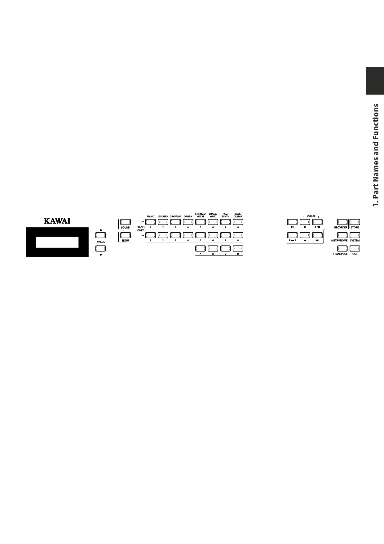
EFFECT BUTTONS
11. SW button
This button turns the assigned function ON or OFF. Many different functions can be
assigned to this switch for your convenience.
When in edit mode, pressing the SW button will exit from edit mode.
12. EFX button
This button turns the EFX ON or OFF for the selected zone.
13. REVERB button
This button turns the REVERB ON or OFF for the selected zone.
To change the function or type assigned to the above buttons, press and hold the
desired button to display the currently selected function or type, then use the VALUE
buttons to change it.
MENU BUTTONS
14. MENU buttons
The MENU buttons are used to enter the edit mode and scroll through all the various
parameters of the MP6. To change a parameter value, use the VALUE buttons.
DISPLAY
15. DISPLAY
s
t
p
q
u
x
r
v
y
w
z
o
VALUE BUTTONS
16. VALUE buttons
The VALUE buttons are used to change the value of the current parameter as indicated
on the DISPLAY.
SOUND SELECTION & SETUP SELECTION
17. SOUND button
The SOUND button switches the MP6 to the SOUND mode. The SOUND SELECT buttons
will now select any of the 256 internal sounds.
18. SETUP button
The SETUP button switches the MP6 to the SETUP mode. The SOUND SELECT buttons
will now select any of the 256 SETUPs.
19. SOUND SELECT buttons
The SOUND SELECT buttons are organized in two rows of eight buttons and one row of
four ones. In SOUND mode the upper row of buttons is used to select a sound category
and the second & third rows of buttons is used to select the different internal sounds within
each category. In SETUP mode the upper row of buttons is used to select a bank and the
second & third rows of buttons is used to select the different SETUPs within each bank.
RECORDER SECTION
20. RECORDER CONTROL buttons
The RECORDER CONTROL buttons are used for Rec/Play functionality in Recorder Mode.
When Recorder Mode is not in use, the RECORDER CONTROL buttons can be used to
send MMC messages to external MIDI devices.
21. RECORDER button
The RECORDER button is used to access the Internal Song and USB Audio recorder
functions.
11
OTHERS
22. METRONOME button
The METRONOME button is used to start or stop the metronome.
23. TRANSPOSE button
The TRANSPOSE button is used to turn the TRANSPOSE function ON/OFF.
24. STORE button
The STORE button is used to store the settings of the MP6.
25. SYSTEM button
The SYSTEM button is used to set the system parameters of the MP6.
26. USB button
The USB button is used to access the MP6’s USB functions: Load, Save, Rename, Delete,
and Format.
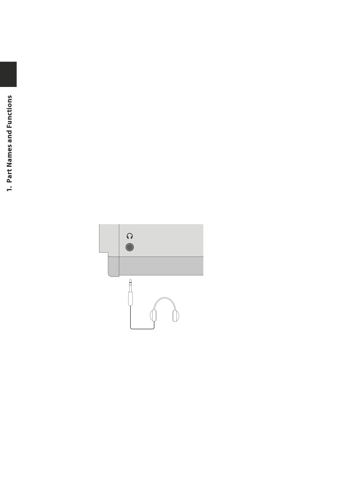
1.2 HEADPHONE JACK
The headphone jack is located in front at the left end of the key slip.
Use a headphone with a standard stereo 1/4 inch phone jack.
12
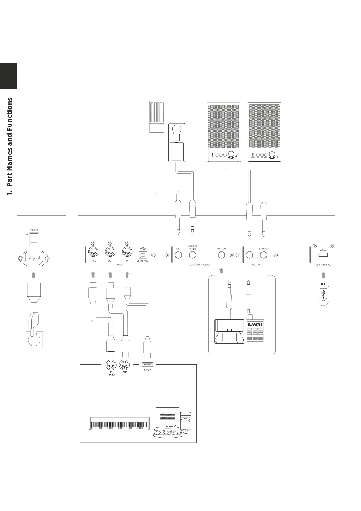
1.3 REAR PANEL
1. POWER SWITCH
Turns the MP6 ON or OFF.
2. POWER RECEPTACLE
Connect the power cable, which is included in the MP6 package, to this receptacle.
3. MIDI JACKS
These jacks are used to connect the MP6 with external MIDI devices such as a MIDI sound
module or a MIDI sequencer.
4. USB to Host PORT
This jack is used to connect the MP6 with a personal computer. See page 86 for details.
5. FOOT CONTROLLERS
EXP JACK
An expression pedal can be connected to this jack.
The expression pedal can be assigned to different MIDI control numbers or functions in
the Menu.
DAMPER JACK
This jack is used to connect the Foot Pedal included with the MP6 (KAWAI F-10H).
6. FOOT SWITCH
A momentary footswitch can be connected to this jack (EX: KAWAI F-1 or F-20). The
FootSwitch can be assigned to different MIDI control numbers or functions in the Menu.
When using the KAWAI F-20. The right pedal works as a Foot Switch, and the left pedal
works as a Soft pedal. When the Rotary EFX is in use, the Soft pedal changes between
Fast & Slow Rotor speeds.
7. OUTPUTS
R, L/MONO OUTPUTS
The R, L/MONO outputs are used to connect the MP6 to a musical instrument amplifier
using standard 1/4 inch phone jacks. The R, L/MONO outputs can also be used to connect
the MP6 to a PA system or recording console.
8. USB TO DEVICE PORT
This port allows a USB memory device to be connected to the MP6.
13
Keyboard amplifier
Expression
PA equipments
Pedal
(Ex. Mixer, Multi-track recorder)
F-10H
c
a
d
e
f
g
h
b
Foot Switch (Optional)
Terminal B
Terminal A
F-20
F-1
MIDI devices
(Ex. External Sound module, External Sequencer,
Keyboards, Personal Computers)
14
2. Basic Operations
2.1 Getting Ready
Since the MP6 has no built-in speakers, you will need to connect a mixer,
keyboard amplifier or headphones in order to listen.
Turn the MP6 on, using the POWER SWITCH on the rear panel.
It is recommended to turn the MP6 on before turning on any amplifiers in order
to avoid switching noise.
What you need to know before starting:
Please read this part for a better understanding of the MP6 structure.
The MP6’s SOUND and SETUP modes are largely the same. The main difference
between the two is that SETUP is used to recall stored SETUPs. Edits and changes
can be made freely in either mode, using the 4 faders, 4 knobs and MENU
functions, however edits made in SOUND mode will be lost when the power is
turned OFF and must therefore be stored in SETUP mode.
In order to start from scratch, use the SOUND mode and press PIANO ONLY
first.
In order to modify a SETUP, select the desired SETUP, perform any edits, and
store the changes as a SETUP.
If selected sounds do not sound correct, it is possible that parameters (knobs
etc.) were edited. To restore sounds to their default setting, use the PIANO ONLY
function, then re-select the desired sound.
15
2.2 Selecting a Sound
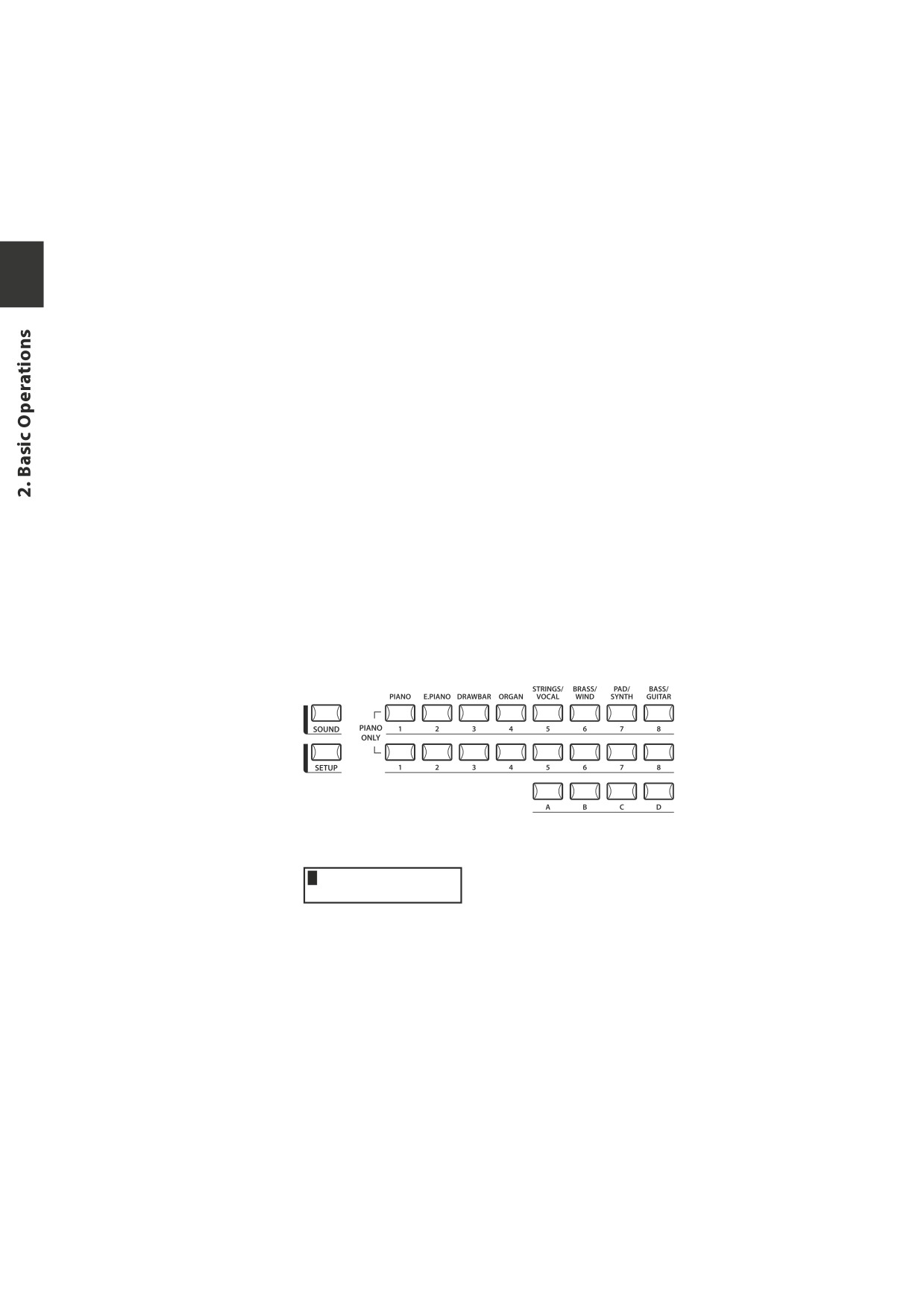
The MP6 always starts up in SOUND mode when the power is turned ON. The
SOUND button will be lit to indicate SOUND mode is active.
Operation 1
Select the sound category by pressing a sound select button in the top row.
There are 3 rows of sound select buttons, the top row is for selecting a sound
category and the second and third rows are for selecting a variation.
For example, to select "60’s EP2", first press the E.PIANO in the top row and the
first sound in the E.PIANO category "Classic EP" is recalled. (If any other variation
was selected before, the last selected sound is recalled as long as the power is
on.)
Operation 2
Select the first variation by pressing a sound select button in the second row.
Press one of the 1-8 buttons in the second row. If you press 3, the variation 3
"60’s EP" is recalled. (If any other variation was selected before, the last selected
sound is recalled as long as the power is on.)
Operation 3
Select the second variation by pressing a sound select button in the third row.
Press one of the A-D buttons in the third row. If you press B, a variation sound
"60’s EP2" is recalled.
Select the variations with the sound select buttons in the second and third
rows.
The display shows the currently selected sound name.
1 Concert Grand
Note:
Internal sounds or Setups can be also selected using the VALUE buttons.
You should also listen to the preprogrammed Setups.
Setups are organized in 8 Banks with 32 Numbers each (total 256 Setups).
Press the SETUP button to change to SETUP mode and select a Setup by pressing
one of the Bank buttons in the upper row followed by a Number button in the
second and third row.
The display shows the currently selected Setup name.
In Sound mode, the “1” in the display indicates that the zone 1 is currently
selected.
16
2.3 Layer
Let’s try layering another sound. Turn the zone 2 on by pressing the ZONE ON/
OFF button for zone 2. The ZONE SELECT button for zone 2 is automatically
selected and the display shows the sound name for zone 2.
Select the sound for zone 2 with the SOUND SELECT buttons as shown in the
previous section.
2 String Pad
Adjust the volume balance of zone 1 and 2 with the faders for each zone.
2.4 Split
Now let’s split the keyboard and play different sounds in upper and lower
sections.
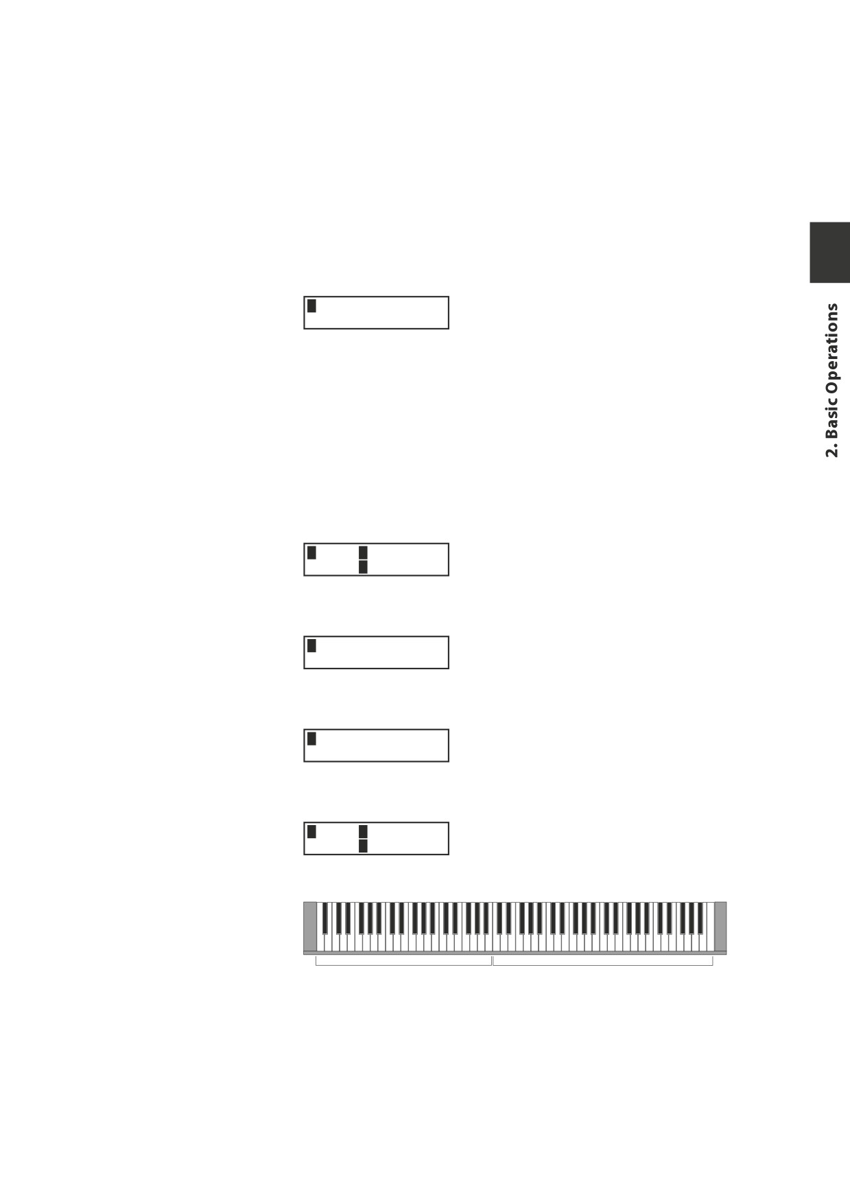
Press and hold the ZONE SELECT button for zone 1. The display shows the key
range for zone 1 as follows.
1Key IA-1 >C7
RangeEA-1 >C7
While still holding down the ZONE SELECT button for zone 1, press the lowest
note on the keyboard. The display changes as follows.
1KeyRange(Both)
= A-1
> ----
While still holding down the ZONE SELECT button for zone 1, select the highest
note for zone 1, for example, B2 by pressing B2 key on the keyboard.
1KeyRange(Both)
= A-1
> B2
Repeat the same procedure for zone 2 while holding down the ZONE SELECT
button for zone 2 and set the key range from C3 to C7.
2Key IC 3> C 7
RangeEC 3> Cc7
Now the keyboard is split as follows.
ZONE1
q
q
ZONE2
B2
C3
Note:
In this method, the key ranges for internal and external zones always change
together. If you want individual settings, use the Key Range Hi/Lo parameter in
MENU (see page 42).
17
2.5 Piano Only
The Piano Only function lets you quickly return the MP6 sounds to the default
settings.
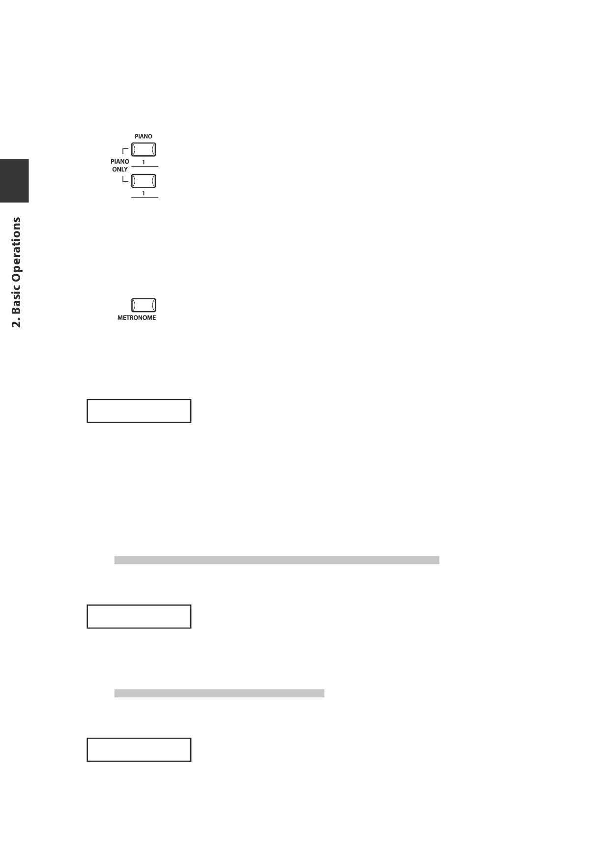
Press the PIANO button and the SOUND SELECT button 1 simultaneously. All the
current settings (except for SYSTEM settings) will go back to original and only
Concert Grand sound can be played on the whole keyboard.
NOTE: You may use this function also as a kind of Panic or Reset button. Also it is a
good starting point to create Setups from scratch.
2.6 Metronome/Drum Rhythms
The Metronome function provides a steady beat to aid practicing the piano
at a consistent tempo. In addition to regular metronome beats, the MP6 also
features a variety of drum rhythms to accompany most musical genres.
Press the METRONOME button to start the metronome.
A beat will start to count and the LED indicators for the STORE and SYSTEM
buttons will flash in time with the sound.
The time signature and tempo will also be shown in the LCD display.
1/4
œ=120
Press the VALUE buttons to increase or decrease the tempo.
* The metronome tempo can be adjusted within the range of 30-300 bpm (60-
600 bpm for eighth note rhythms).
* The metronome configuration can be stored to a SETUP/POWER ON memory.
Press the MENU buttons to show the metronome time signature/pattern or
metronome volume screens in the LCD display.
Changing the Metronome time signature/drum rhythm
When ‘Pattern’ is shown in the LCD display:
Press the VALUE buttons to selected the desired time signature/drum rhythm.
Pattern
1/4
* There are ten different types of time signature available:
1/4, 2/4, 3/4, 4/4, 5/4, 3/8, 6/8, 7/8, 9/8, and 12/8.
* Please refer to page 82 of this owner’s manual for a full list of available drum rhythms.
Changing the Metronome volume
When ‘Metro Volume’ is shown in the LCD display:
Press the VALUE buttons to increase or decrease the metronome volume.
1/4
* The metronome volume can be adjusted within the range of 0-10.
Metro Volume =10
Press the EXIT button to return to the previous screen.
18
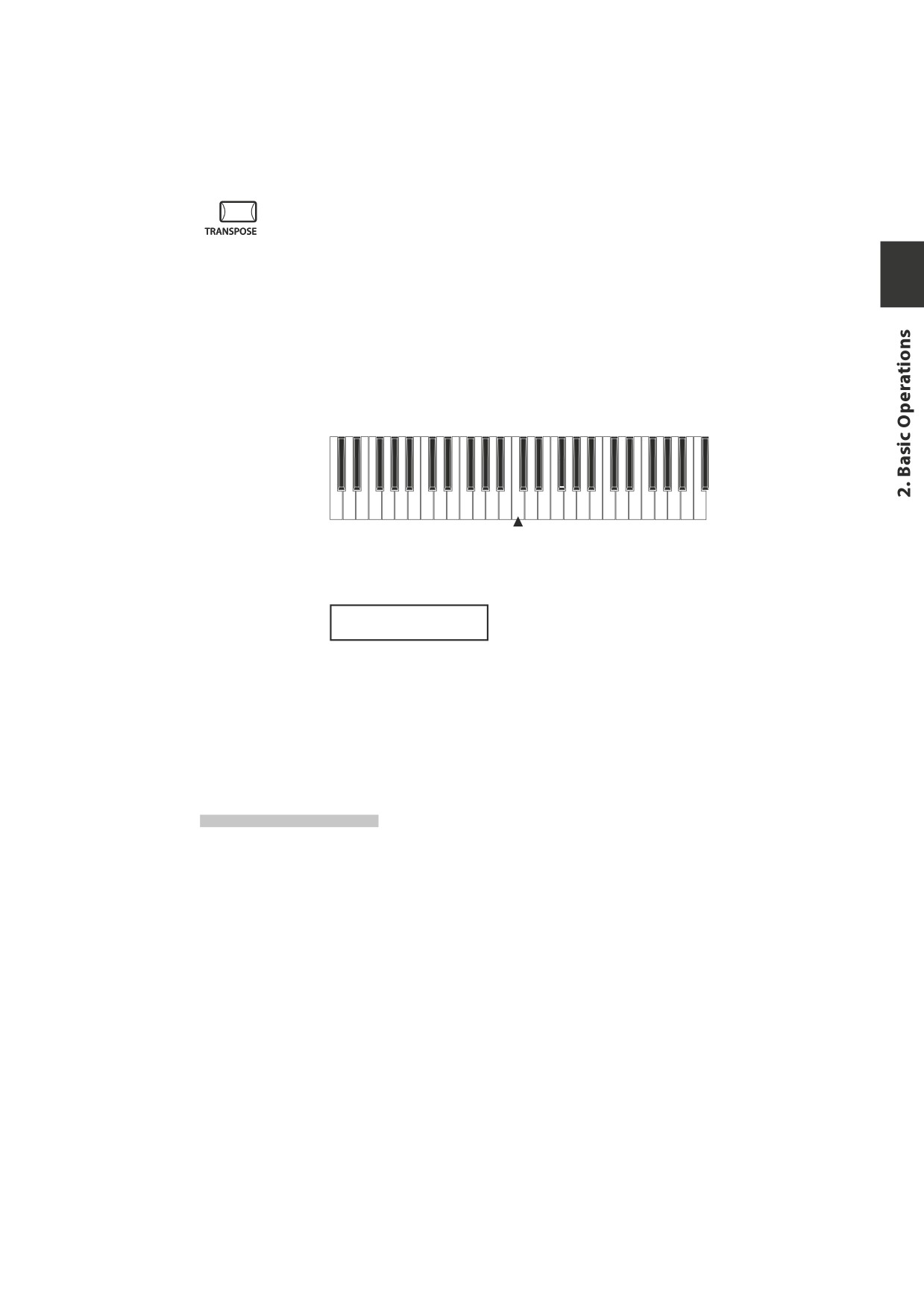
2.7 Transpose
When the Transpose function is “ON” the MP6’s key can be raised or lowered
in half steps. The available range of transposition is 24 semitones, either up or
down.
While holding down the TRANSPOSE button, press any key on the MP6 keyboard
to select a new transposed key. Pressing the F key above middle C for example
will transpose the MP6 UP to the key of F (+5 half steps).
The transpose amount can also be set using the VALUE buttons.
While holding the TRANSPOSE button down, press the VALUE buttons to change
the transpose amount.
-24
-12
0
+12
+24
C3
The display shows the current TRANSPOSE amount when the TRANSPOSE
button is held down. A value of “0” indicates no transposition.
MASTER TRANS
+10
2.8 Using the MP6 as a MIDI controller
The MP6 can control external devices via MIDI.
MIDI Connection
Connect the MIDI OUT on the MP6 to the MIDI IN on an external MIDI device
with a MIDI cable.
19
Selecting the MIDI Channel
The MIDI Transmit Channel of the MP6 must be matched with the Receive
Channel of any MIDI devices connected to the MP6.
Select zone 3 by pressing the ZONE SELECT button 3. (Zone 3 is set to external
as default setting.)
Press the MENU c button until “TrsChannel” (Transmit Channel) appears on the
display.
3Externel
STrsChannel =
1
Use the VALUE buttons to choose a MIDI Transmit Channel from 1 to 16.
To exit from MENU, press the EXIT(SW) button.
Any notes played on the keyboard or any movements of the Knobs, sliders, etc.
will be transmitted to any external MIDI devices connected to the MIDI out of
the MP6 on the selected MIDI channel.
Sending Program Change Number
The MP6 can send MIDI program change numbers from 1 to 256 and Bank
number LSB from 0 to 1 in SOUND mode. Simply press the SOUND SELECT
buttons and the corresponding program number will be transmitted. See the
program number table below.
UPPER
SECOND
THIRD
PROG#:MSB-LSB
1
1
A
001:000-000
1
1
B
002:000-000
1
1
C
003:000-000
1
1
D
004:000-000
1
2
A~D
005:000-000 ~ 008:000-000
1
3
A~D
009:000-000 ~ 012:000-000
1
4
A~D
013:000-000 ~ 016:000-000
1
5
A~D
017:000-000 ~ 020:000-000
1
6
A~D
021:000-000 ~ 024:000-000
1
7
A~D
025:000-000 ~ 028:000-000
1
8
A~D
029:000-000 ~ 032:000-000
2
1~8
A~D
033:000-000 ~ 064:000-000
3
1~8
A~D
065:000-000 ~ 096:000-000
4
1~8
A~D
097:000-000 ~ 128:000-000
5
1~8
A~D
001:000-001 ~ 032:000-001
6
1~8
A~D
033:000-001 ~ 064:000-001
7
1~8
A~D
065:000-001 ~ 096:000-001
8
1~8
A~D
097:000-001 ~ 128:000-001
20
The transmitted program number is shown in the display.
3
001:000-000 01
You can also send program change numbers by using VALUE buttons.
Note:
Full program change numbers including bank numbers can be transmitted by
setting them in MENU and saving it as a SETUP. See page 39/40 for details.
2.9 Selecting a SETUP
The MP6 offers 256 preset combinations of the panel settings called SETUPs.
To select a SETUP, press the SETUP button. Now the SOUND SELECT buttons are
used to select a SETUP. Use a combination of the numbers in the upper, second
and third rows to select a desired SETUP. The display will show the selected
SETUP name.
GrandPno1+Str1
To check the sound (internal) or program number (external) assigned to each
zone, press the ZONE SELECT button. The display briefly shows the assigned
sound name or program number, and then automatically returns to the SETUP
name in a few seconds.
If you hold a ZONE SELECT button for 2 seconds the display will show you the
key range information for that zone. You can also set the key range using the
same procedure that is used in Sound mode.
21
3. SW Button
The SW button is a programmable realtime switch which can be assigned to one
of 8 different functions.
Press and hold the SW button. The display shows the currently assigned function.
Press the SW button again to exit without changing the function.
SW TYPE/COMMON
1:Panel Lock
Use the VALUE buttons to change the function. The display will automatically
return to SOUND or SETUP mode after you change the function.
This function can be stored using the STORE button. (see page 55)
When the MENU function is displayed, the SW button works as an EXIT button.
3.1 Panel Lock
You can lock the panel operation to avoid unnecessary changes to the settings
by accident.
When the SW button is lit Panel Lock is ON.
Panel Lock On: All the operations except for keyboard, wheels, pedals and SW
button are locked. The display shows as follows while the panel is locked.
Panel Lock
>Press[SW]button
Panel Lock Off: Panel Lock is canceled.
3.2 Touch Curve
You can temporary turn on/off the Touch Curve for example to play organ
sounds correctly.
Touch Curve On: The display briefly shows the selected Touch Curve in the
SYSTEM and the Touch Curve becomes active. If the selected Touch Curve in the
SYSTEM is Off, the Normal Touch Curve becomes active.
Touch Curve Off: The display briefly shows as follows and the Touch Curve
becomes Off.
Touch Curve
Off
22
3.3 Rotary Slow/Fast
You can switch the speed of roter between slow and fast when the Rotary effect
is in use.
When the SW button is lit: The display briefly shows as follows and the rotary
speed changes to fast.
Rotary Speed
Fast
When the SW button is OFF: The display briefly shows as follows and the rotary
speed changes to slow.
Rotary Speed
Slow
Note:
When the Rotary effect is not in use, the display briefly shows as follows.
Rotary is
not selected.
3.4 EQ Bypass On/Off
You can temporarily bypass the EQ by turning the SW button on.
When the SW button is lit the EQ Bypass is on.
EQ Bypass On: The display briefly shows as follows and the sound bypasses the
EQ.
EQ Bypass
On
EQ Bypass Off: The display briefly shows as follows and the EQ comes back to
active.
EQ Bypass
Off
Note:
When the EQ Bypass is turned on and the EQ control knobs are used, the display
briefly shows as follows.
EQ Bypass
>Press[SW]button
23
3.5 Wheel Lock
You can lock the bender wheel and modulation wheel to avoid unnecessary
movement by accident.
When the SW button is lit the Wheel Lock is on.
Wheel Lock On: The display briefly shows as follows and the wheels are locked.
Wheel Lock
On
Wheel Lock Off: The display briefly shows as follows and the wheels are
unlocked.
Wheel Lock
Off
Note:
When the Wheel Lock is turned on and the wheels are used, the display briefly
shows as follows.
Wheel Lock
>Press[SW]button
3.6 Foot Switch Lock
You can lock the assignable foot switch to avoid unnecessary movement by
accident.
First, connect a foot switch to the FSW jack on the rear panel of the MP6.
When the SW button is lit the Foot Switch Lock is on.
Foot Switch Lock On: The display briefly shows as follows and the assignable
foot switch is locked.
FSW Lock
On
Foot Switch Lock Off: The display briefly shows as follows and the assignable
foot switch is unlocked.
FSW Lock
Off
Note:
When the FSW Lock is turned on and the foot switch is used, the display briefly
shows as follows.
FSW Lock
>Press[SW]button
24
3.7 Expression Pedal Lock
You can lock the expression pedal to avoid unnecessary movement by
accident.
First, connect an expression pedal to the EXP jack on the rear panel of the MP6.
When the SW button is lit the Expression Pedal Lock is on.
Expression Pedal Lock On: The display briefly shows as follows and the expression
pedal is locked.
EXP Lock
On
Expression Pedal Lock Off: The display briefly shows as follows and the expression
pedal is unlocked.
EXP Lock
Off
Note:
When the EXP Lock is turned on and the expression pedal is used, the display
briefly shows as follows.
EXP Lock
>Press[SW]button
3.8 Amp Simulator On/Off (ZONE1 only)
You can enable an Amp Simulator effect by turning the SW button on.
When the SW button is lit the Amp Simulator is on.
Amp Simulator On: The display briefly shows as follows and the Amp Simulator
turns on.
Amp Simulator
On
Amp Simulator Off: The display briefly shows as follows and the Amp Simulator
turns off.
Amp Simulator
Off
Note:
The Amp Simulator will be effective for ZONE 1 only.
* Please refer to page 38 of this owner’s manual for further details regarding the
Amp Simulator.
25
4. EFX / REVERB Buttons
The internal sounds of the MP6 can be enhanced using the built in REVERB and
EFX generators.
There are 7 REVERB types and 23 different EFX types to choose from. MP6
contains 4 variations of EFX type per INT section, and different EFX can be added
to the sound of each ZONE.
4.1 EFX
The MP6 contains 23 high quality EFX types, designed to complement the
internal sounds. Each internal sound has a preset effect assigned as the default.
The EFX button turns the EFX generator ON or OFF for the selected sound.
To turn the EFX “ON” for the current sound, press the EFX button and the button
will light up. EFX will be added to the current sound.
To turn the EFX “OFF” again, press the EFX button again (the light on the button
will be turned off).
EFX type
Press and hold the EFX button for a few seconds. The display shows EFX type
added to the current selected ZONE.
1
EFX TYPE
18: Rotary 1
Use the VALUE buttons to change the effect type. Each EFX type has a default
value for RATE and DEPTH, so when changing the EFX type, the values are
changed automatically. You can edit these values with the EFX RATE and EFX
DEPTH knobs in the first row of the CONTROL KNOBS section on the panel.
To select another ZONE, press its ZONE SELECT button.
Chorus
Chorus is a slight detuning of the sound, which adds depth and
richness to the sound.
Flanger
Flanger introduces a shifting comb-filter, which adds motion and a
“hollow” tone to the sound.
Celeste
Celeste is a three phase chorus, with each of the three chorus units
at different phase.
Ensemble
Ensemble is a three phase chorus, with each of the three chorus
units at a different phase and frequency. This gives a slightly richer
sound than the Celeste effect, above.
Delay 1/2/3/4
Delay adds echoes to the sound.
AutoPan 1/2/3
AutoPan alternates the sound left and right across the stereo field
at a variable rate. AutoPan 3 includes an overdrive effect.
Tremolo 1/2/3/4
Tremolo changes the volume of the sound, making it louder and
softer at a variable rate. Tremolo 3 includes an overdrive effect.
Phaser 1/2
Phaser creates a cyclic phase change, adding motion to the sound.
26
Rotary 1/2
The Rotary effect simulates the sound of the rotary speaker cabinet
commonly used with electronic organs. Rotary 2 includes an
overdrive effect.
Auto Wah
Auto Wah creates an automatic filter sweep at the attack of each note.
Pedal Wah
Pedal Wah creates a filter sweep with the expression pedal
connected to the MP6.
Enhancer
Enhancer produces a crisper tone, so the sound is more easily
discernible.
Overdrive
Overdrive effect adds tube-amp style distortion.
Note: You can select different EFX types for each zone.
4.2 REVERB
The MP6 contains 7 high quality REVERB types, designed to complement the
internal sounds. Each internal sound has a preset REVERB type assigned as
the default. The REVERB button turns the REVERB generator ON or OFF for the
selected sound.
To turn the REVERB “ON” for the current sound, press the REVERB button and the
button will light up. REVERB will be added to the current sound.
To turn the REVERB “OFF” again, press the REVERB button again (The light on
the button will be turned off).
REVERB type
Press and hold the REVERB button until the display shows REVERB type.
REVERB TYPE
1 :Hall 1
Use the VALUE buttons to change the REVERB type. Each REVERB type has a
default value for TIME, so when changing the REVERB type, the value is changed
automatically.
Hall 1
Simulates the reverb in a standard hall
Hall 2
Simulates the reverb in a small hall
Stage 1
Simulates the reverb on a standard stage
Stage 2
Simulates the reverb on a small stage
Room 1
Simulates the reverb in a standard room
Room 2
Simulates the reverb in a small room
Plate
Simulates the reverb of a metallic plate
Note: REVERB type is common to all internal zones. You cannot select a different
type for each zone. But you can individually turn on/off or set different depths for
each zone.
27
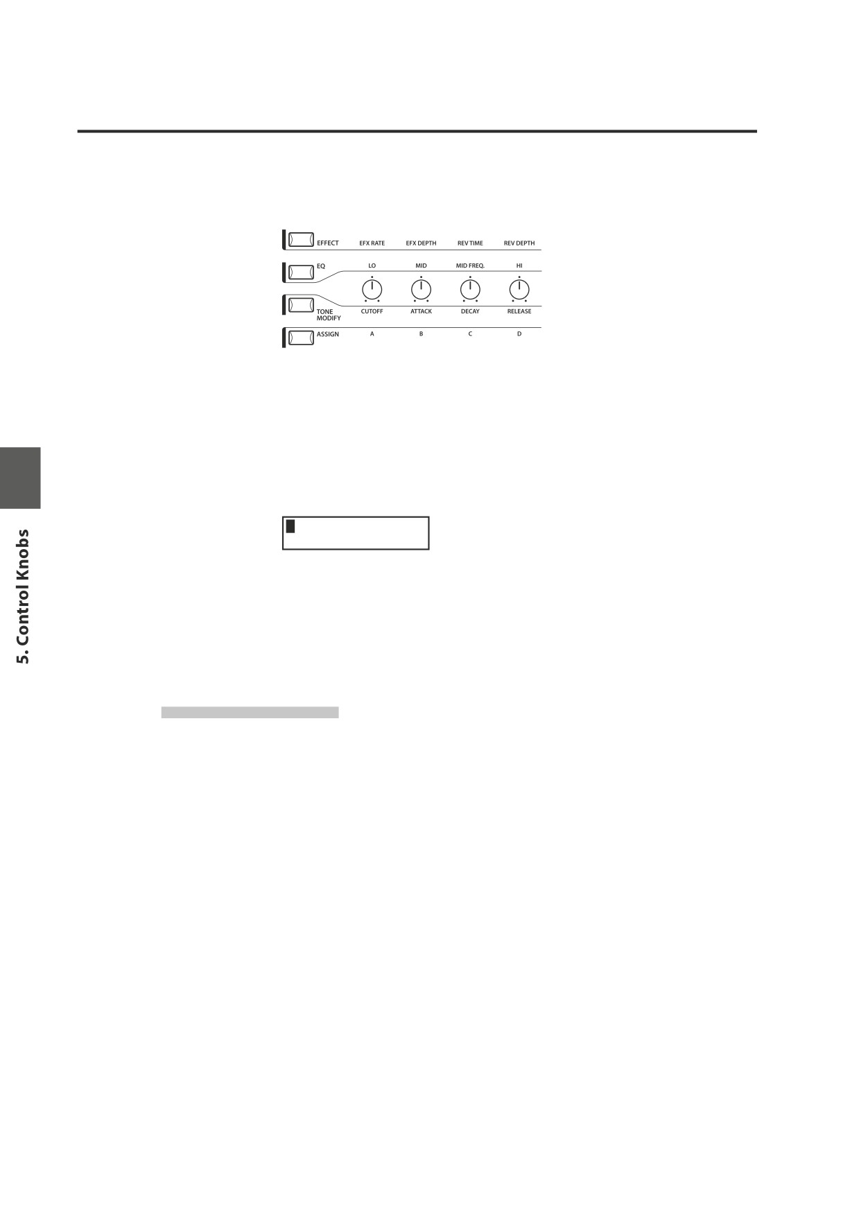
5. Control Knobs
Select the function with the buttons on the left and use the knobs to change
the values. You can also move the cursor with the MENU buttons and change
the value with the VALUE buttons while the display is showing Control Knobs
function.
5.1 EFFECT
Make sure that the EFFECT button in the CONTROL KNOBS section is lit. If the
EFFECT button is turned off, press it to turn it ON.
The CONTROL KNOBS are now active and assigned to the EFX/REVERB parameters
for the selected zone. Use the CONTROL KNOBS to change the current settings.
1EfR EfD RvT RvD
64
96 127
41
EfR (EFX Rate) adjusts the value of the preset parameter for each EFX. (internal
only)
EfD (EFX Depth) adjusts the depth of the EFX added to the sound.
RvT (REVERB Time) adjusts the reverb time. (internal only)
RvD (REVERB Depth) adjusts the depth of the reverb added to the sound.
EFX parameter list
EFX Rate
EFX Depth
1.
CHORUS
rate
0 -12.7Hz
dry/wet
2.
FLANGER
rate
0 -12.7Hz
dry/wet
3.
CELESTE
rate
0 -12.7Hz
dry/wet
4.
ENSEMBLE
rate
0 -12.7Hz
dry/wet
5.
DELAY 1
delay time
0.650ms
wet level
6.
DELAY 2
delay time
0.650ms
wet level
7.
DELAY 3
delay time
0.325ms
wet level
8.
DELAY 4
delay time
0.650ms
wet level
9.
AUTO PAN 1
rate
0 -12.7Hz
depth
10. AUTO PAN 2
rate
0 -12.7Hz
depth
11. AUTO PAN 3
rate
0 -12.7Hz
depth
12. TREMOLO 1
rate
0 -12.7Hz
depth
13. TREMOLO 2
rate
0 -12.7Hz
depth
14. TREMOLO 3
rate
0 -12.7Hz
depth
15. TREMOLO 4
rate
0 -12.7Hz
depth
16. PHASER 1
rate
0 -12.7Hz
dry/wet
17. PHASER 2
rate
0 -12.7Hz
dry/wet
18. ROTARY 1
slow/fast
-
dry/wet
28
19. ROTARY 2
slow/fast
-
drive
20. AUTO WAH
sense
0 -127
dry/wet
21. PEDAL WAH
sense
0 -127
dry/wet
22. ENHANCER
intensity
0 -127
wet level
23. OVERDRIVE
drive
0 -127
dry/wet
REVERB parameter list
REVERB Time
REVERB Depth
1.
HALL 1
rev.time
0.3 - 8.0s
send level
2.
HALL 2
rev.time
0.3 - 8.0s
send level
3.
STAGE 1
rev.time
0.3 - 5.0s
send level
4.
STAGE 2
rev.time
0.3 - 5.0s
send level
5.
ROOM 1
rev.time
0.3 - 3.0s
send level
6.
ROOM 2
rev.time
0.3 - 3.0s
send level
7.
PLATE
rev.time
0.3 - 3.0s
send level
Note:
When EFX/REVERB depth is set to 0 while the EFX/REVERB button is active, the
EFX/REVERB button will blink to indicate that the EFX/REVERB is turned ON but
the depth is set to 0.
EFX rate and REVERB time are effective to internal zone only.
If the selected zone is set to BOTH, changing the value for EFX depth or REVERB
depth affects for both internal and external sections. If you want different settings
for internal and external sections, first enter the edit mode by pressing the MENU
button and press the EFFECT button. Now you can select internal or external zone
with ZONE SELECT button. (See page 35 for details.)
Quick Change Reverb Offset
Press and hold the EFFECT button. The EFFECT button starts blinking and the
following screen for Reverb Offset (see page 60) will be shown until the button
is released.
Rev.Offset
100%
This parameter is stored automatically when leaving the screen, there is no need
to store the setting manually.
29
5.2 EQ (EQUALIZER)
The MP6 contains a three-band graphic equalizer to shape the overall tone of
the sound. The EQ affects all zones at the same time. However, each SETUP can
have its own EQ setting that affects the internal sounds only.
Be sure that the EQ button in the CONTROL KNOBS section is lit.
If the EQ button is turned off, press it to turn it ON.
The CONTROL KNOBS are now active and assigned to the EQ parameters. Use
the CONTROL KNOBS to change the current settings.
Each parameter of the EQ has an adjustable range from -9 to +9. A positive (+)
value indicates amplification, or a boost of that frequency range. A negative (-)
value indicates attenuation, or a cut of that frequency range.
The MFreq parameter has an adjustable range from 355Hz to 2500Hz.
Lo, Mid, Hi
-9 - +9
Lo Mid MFrq Hi
+9
-9 2240 +9
MFrq (Hz)
355, 400, 450, 500, 560, 630, 710, 800, 900, 1000, 1120, 1250, 1400,
1600, 1800, 2000, 2240, 2500
Quick Change EQ Offset
Press and hold the EQ button. The EQ button starts blinking and the following
screen for EQ Offset (see page 60) will be shown until the button is released.
EQ Offset
+0
-1
+9
This parameter is stored automatically when leaving the screen, there is no need
to store the setting manually.
If EQ Offset is set to Off in System parameters, this page will not be displayed.
30
5.3 TONE MODIFY
The MP6 allows certain characteristics of the sounds to be custom tailored
to suit a particular musical or playing style, or to create many variations and
different types of sounds. TONE MODIFY settings can be done for each zone
individually.
The following parameters are provided:
CUTOFF, ATTACK, DECAY and RELEASE.
Make sure that the TONE MODIFY button in the CONTROL KNOBS section is lit.
If the TONE MODIFY button is turned off, press it to turn it ON.
The CONTROL KNOBS are now active and assigned to the Tone Modify
parameters for the current sound.
Use the CONTROL KNOBS to change the current settings for the selected zone.
Each parameter of the TONE MODIFY function has an adjustable range from -50
to +50.
1CUT ATK DCY RLS
-50 +40 -20
+50
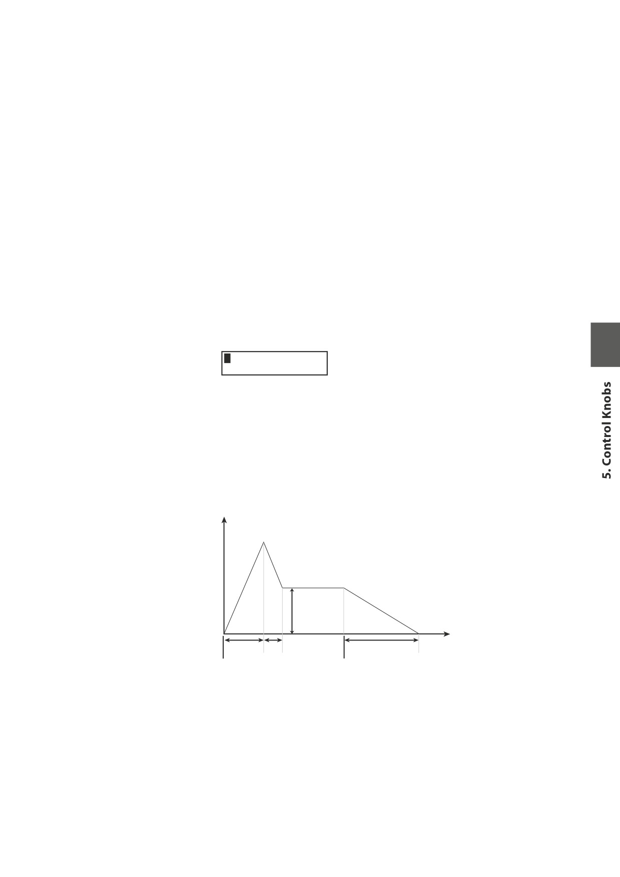
CUTOFF:
Raising the CUTOFF level makes the sound brighter, lowering
the level makes the sound duller.
ATTACK:
As the value increases, the attack time becomes longer, which
means a slower attack is produced.
DECAY:
This parameter controls the amount of time from the peak
level to the sustain level of the sound.
RELEASE:
This parameter controls the amount of time needed for the
sound to fade out after the key is released.
Volume level
Sustain
Level
Time
Attack
Release
Decay
KeyOn
KeyOff
Note:
If the selected zone is set to BOTH, changing the TONE MODIFY parameters affects
both internal and external sections. If you want different settings for internal and
external sections, enter the edit mode by pressing the MENU button and select
internal or external section with the ZONE SELECT button. (See page 35 for details.)
31
5.4 ASSIGN
The ASSIGN button can be used to set the CONTROL KNOBS to send MIDI
Continuous Controller information to external MIDI devices, or to control the
MP6’s Amp Simulator function.
5.4.1 Amp Simulator parameter
If the Amp Simulator is turned on, pressing the ASSIGN button allows the Amp
Simulator parameters to be adjusted using the CONTROL KNOBS.
Drv Lvl Lo Hi
0 127
0
0
Note:
The Amp Simulator is effective for Zone 1 only.
* Please refer to page 38 of this owner’s manual for further information about
the Amp Simulator.
5.4.2 MIDI CC# (Control Change)
If the Amp Simulator is turned off, pressing the ASSIGN button allows MIDI
Continuous Controller information to be sent using the CONTROL KNOBS.
The MP6 can send any MIDI Continuous Controller information to any MIDI
Instrument or Device. This powerful feature allows for editing the sounds of an
external sound module in Real Time during performance, or for recording Real
Time performance edits to a MIDI sequencer.
Some control changes are also effective to internal sounds.
Make sure that the ASSIGN button in the CONTROL KNOBS section is lit. If the
ASSIGN button is turned off, press it to turn it ON.
The CONTROL KNOBS are now active and assigned to the MIDI CC parameters.
Use the CONTROL KNOBS to change the MIDI continuous controller information
assigned to each knob as described below.
Each parameter of the Control Change has an adjustable range from 0 to 127.
When the selected zone is set to INT or BOTH, the display shows the parameter
names.
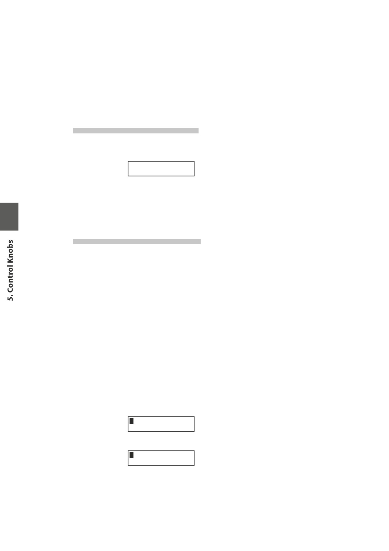
1PAN STN VbR3VbD
0
0
0
0
When the selected zone is set to EXT, the display shows the MIDI CC numbers.
3010 070 076 077
64
64
64
64
32
The default parameters assigned for each knob are as follows.
A: #10 Panpot (PAN)
B: #70 Sustain Level (STN)
C: #76 Vibrato Rate (VbR)
D: #77 Vibrato Depth (VbD)
Note:
If the selected zone is set to BOTH, changing the MIDI CC# parameters affects both
internal and external sections. If you want different settings for internal and external
sections, enter the edit mode by pressing the MENU button and select internal or
external section with the ZONE SELECT button. (See page 35 for details.)
Changing MIDI CC parameter
Press and hold the ASSIGN button. ASSIGN button starts blinking and the cursor
in the display moves up to the parameter name.
1PA
N STNVbRVbD
0
0
0
0
Use the CONTROL KNOBS to change the parameters.
After changing the parameter, press the ASSIGN button again. The ASSIGN
button stops blinking and the cursor in the display moves down to the value.
If
“AFT” is selected, the modulation wheel is used to send After Touch
information.
Note:
When the selected zone is set to INT, only the following parameters can be
selected.
10
Panpot
PAN
70
Sustain Level
STN
71
Resonance
RSN
72
Release
RLS
73
Attack
ATK
74
Cutoff
CUT
75
Decay
DCY
76
Vibrato Rate
VbR
77
Vibrato Depth
VbD
78
Vibrato Delay
VbY
93
Chorus Depth
ChD
When the selected zone is set to BOTH and the internal section is selected in edit
mode, the parameters not available for INT section show as “ XXX”.
1015 STN VbR VbD
Ixx
0
0
0
x
33
6. MENU Buttons
The MENU buttons allow access to the edit parameters in the MP6. This collection
of settings together with other editable parameters can be stored as a SETUP.
The MP6 provides 256 SETUPs, and all are user programmable.
A SETUP consists of four zones. Each zone can be set as Internal, External or Both
individually. Inside each of the four zones, a multitude of features and effects
can be programmed and combined together into one exciting SETUP.
A total of 256 SETUPs may be programmed in this way.
The menu consists of Internal parameters, External parameters and Common
parameters.
Common parameter affect all zones. If a zone is set as Both, both the Internal
parameters and External parameters are available for the zone.
Use the MENU buttons to scroll through all the different parameters.
In SOUND mode, both the Int Zone parameters and the Common parameters
without the inverse “S(Setup)” icon can be individually stored. (see page 55)
The Int Zone parameters can be stored as a SOUND of the MP6’s 256 SOUNDs.
The Common parameters can be stored as the initial settings in SOUND mode.
Zone parameters (Int)
Zone parameters (Ext)
Common parameters
Zone Mode
Zone Mode
Stretch Tuning
Sound (Int only)
Trs Channel
Temperament
Damper Resonance (Int Piano only)
Trs PRG#
Key of Temperament
String Resonance (Int Piano only)
Trs Bank Select MSB LSB
User Tuning
KeyOff Effect (Int Piano only)
Keyboard On/Off
Foot SW CC#
Voicing (Int Piano only)
Velocity Dynamics
EXP CC#
KeyOff Noise (Int EP only)
Solo On/Off
Modulation Wheel CC#
KeyOff Delay (Int EP only)
Solo mode
Left Pedal Mode
Tone Wheel Registration (ZONE1 Int Tone Wheel only)
Damper Pedal On/Off/Hold
Master Volume
Tone Wheel Percussion (ZONE1 Int Tone Wheel only)
Footswitch On/Off
Tone Wheel Percussion Level (ZONE1 Int Tone Wheel only)
Expression Pedal On/Off
Tone Wheel Percussion Decay (ZONE1 Int Tone Wheel only)
Modulation On/Off
Tone Wheel Percussion Harmonics (ZONE1 Int Tone Wheel only)
Bender On/Off
Key Click Level (Int Drawbar Organ only)
Bender Range
EFX Type
Key Range Hi/Lo
EFX parameter
Velocity Switch On/Off
Amp Simulator On/Off (ZONE1 Int only)
Velocity Switch Value
Amp Simulator Drive (ZONE1 Int only)
Zone Transpose
Amp Simulator Level (ZONE1 Int only)
Volume
Amp Simulator EQ Hi/Lo (ZONE1 Int only)
Pan
Velocity Dynamics
Fine Tune
Solo On/Off
Solo Mode
Damper Pedal On/Off/Hold
Foot Switch On/Off
Expression Pedal On/Off
Modulation On/Off
Bender On/Off
Bender Range
Key Range Hi/Lo
Velocity Switch On/Off
Velocity Switch Value
Caution:
Zone Transpose
The edited settings will be erased when the power is turned off, or other sound is
Volume
recalled. To save these settings, use the STORE procedure to save them as a SETUP.
Pan
(see page 56)
Fine Tune
34
6.1 Editing Procedure and Parameters
First, press the ZONE SELECT button for the zone to be edited.
Next, press the MENU buttons until the parameter you want to edit appears in
the DISPLAY. When a zone is set as Both, pressing the ZONE SELECT button again
will switch the menu list from Internal to External or vice versa.
Set the value of the parameter using the VALUE buttons.
Since each parameter has a different value range, consult the following pages
for the details. Repeat this procedure for any other parameters in any of the
zones that need to be modified.
Save these settings using the STORE button.
(See page 53 for detail)
Note:
Once you enter the edit mode from SETUP mode by pressing the MENU button,
the mode automatically changes to SOUND mode and the SOUND SELECT buttons
are used to select sounds, not SETUPs.
You can exit the edit mode by pressing the EXIT(SW) button. Any edits you have
made so far will be retained to SOUND mode. If you exit the edit mode by pressing
SOUND or SETUP buttons, your changes will be lost and the previously saved
settings are recalled.
6.2 Edit Parameters
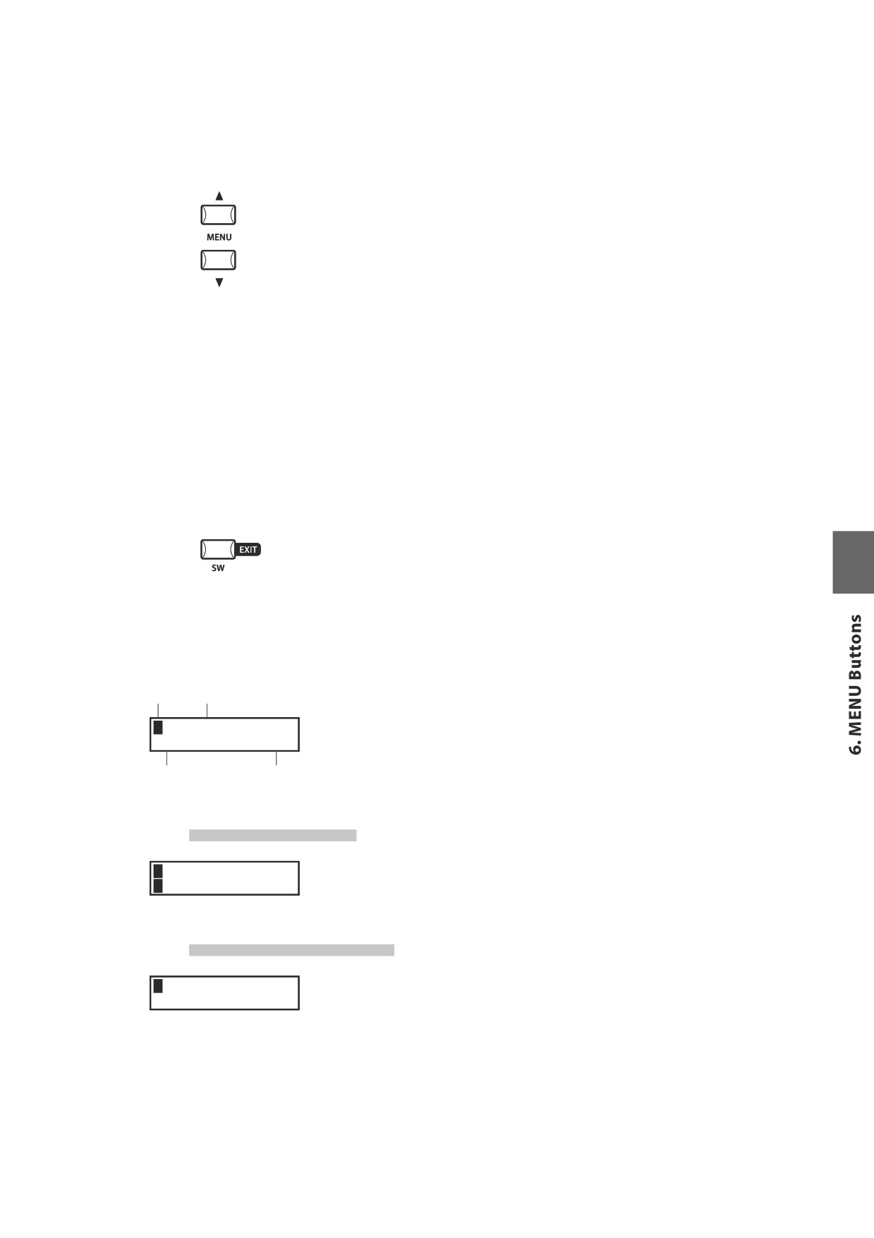
Zone No. Sound Name
Zone parameters can be edited individually for each zone. There are two
parameter groups, Internal parameter group and External parameter group. If
1 Classic EP
a zone is set to Int, only Internal parameters are available for editing. If a zone is
Vel Comp.
= 10
set to Ext, only External parameters are available for editing. If a zone is set to
Parameter
Value
Both, both Internal and External parameters are available for editing.
6.2.1 Zone Mode
This parameter sets the Zone mode. The example shows that the Zone 1 is set
1 Concert Grand
SZone Mode =Both
to Both mode.
6.2.2 Sound (Int only)
This parameter determines which internal sound is assigned for the selected
1Internal Sound
= Concert Grand
zone.
35
6.2.3 Damper Resonance (Int Piano only)
When the sustain pedal is depressed, the volume of the whole resonance can be
1 Concert Grand
Damper Reso.= 1
changed to the level you prefer. The value changes from 0 (off) to 10.
* The display shows this parameter only when Piano sound is selected.
6.2.4 String Resonance (Int Piano only)
The volume of string resonance can be changed to the level you prefer. The
1 Concert Grand
String Reso.= 1
value changes from 0 (off) to 10.
About String Resonance
In acoustic pianos, there are strings corresponding to each key. When a key is pressed,
strings of other keys in the related harmonic series to the note played resonate. This effect
is called "sound resonance", which makes the sound of an acoustic piano full and rich.
* The display shows this parameter only when Piano sound is selected.
6.2.5 Key-off Effect (Int Piano only)
Especially for low-pitched tones, when a key is played strongly and released
1 Concert Grand
quickly, there will be the sound of the damper touching the strings immediately
KeyoffEffect= 1
before the sound stops. The key-off effect simulates this phenomenon, and
allows you to adjust the key-off volume to your taste. The value changes from
0 (off) to 10.
* The display shows this parameter only when Piano sound is selected.
6.2.6 Voicing (Int Piano only)
This parameter re-creates electronically the voicing technique of adjusting the
1 Concert Grand
action, hammers and strings on an acoustic piano to change the tone character.
Voicing= Normal
This function is a very powerful way to enhance and customize the piano
response for each player and each sound.
The effect is only available for the internal piano sounds - other sounds cannot
use this parameter.
Normal
Produces the normal tone of an acoustic piano throughout the entire
dynamic range.
Mellow 1/2
Reproduces the effect of a softer hammer surface. It produces a mellower
tone throughout the entire dynamic range.
Dynamic
This setting is not possible with an acoustic piano. Softly played notes
will have the tone of a mellow voicing and notes played harder will have
the tone of a bright voicing. This setting produces a dramatic change
from mellow to bright throughout the entire dynamic range.
Bright 1/2
Produces a brighter tone throughout the entire dynamic range.
* The display shows this parameter only when Piano sound is selected.
36
6.2.7 KeyOff Noise (Int EP only)
Vintage electric pianos often produce a distinctive sound when the keys are
1 Classic EP
KeyOffNoise = 10
released. The MP6 simulates this characteristic, and the KeyOff Noise parameter
allows you to adjust the volume of the sound to your taste. The value changes
from 0 (off) to 10.
* The display shows this parameter only when an Electric Piano sound is selected.
6.2.8 KeyOff Delay (Int EP only)
This parameter adjusts the delay of the electric piano KeyOff sound. The value
1 Classic EP
KeyOffDelay = 10
changes from 0 to 127.
* The display shows this parameter only when an Electric Piano sound is selected.
6.2.9 Tone Wheel Registration (ZONE1 Int Tone Wheel only)
The MP6’s Tone Wheel Simulation recreates the sound of a vintage tone wheel
organ, and allows each drawbar to be individually adjusted in realtime.
Note:
The Tone Wheel Simulation is activated by selecting Drawbar sounds 6-8.
When Drawbar sounds 1-5 are selected, PCM sounds will be used and the
Tone Wheel Simulation functions will not be shown.
Press the VALUE c button to enter Tone Wheel registration mode,
1 T.Wheel A-1 ≥
Enter RegistMode
ø
Press the MENU buttons to select the drawbar to be adjust, then press the VALUE
TW A-1 ~~~¥¥¥
888444200
buttons to increase or decrease the value (position) of the drawbar.
The four Zone faders can be used to adjust the drawbar setting.
The cursor indicates the drawbar assigned to the Zone1 fader, with the
neighboring drawbars controlled by the Zone 2, 3, and 4 faders.
Press the EXIT button to return to the previous menu.
6.2.10 Tone Wheel Percussion (ZONE1 Int Tone Wheel only)
This parameter is used to turn the percussion sound of the Tone Wheel simulation
1 T.Wheel A-1
Percussion = On
on or off. Press the VALUE buttons to change the setting.
6.2.11 Tone Wheel Percussion Level (ZONE1 Int Tone Wheel only)
This parameter is used to set the volume of the Tone Wheel percussion to either
1 T.Wheel A-1
PercsLevel =Soft
Normal or Soft. Press the VALUE buttons to change the setting.
37
6.2.12 Tone Wheel Percussion Decay (ZONE1 Int Tone Wheel only)
This parameter is used to set the decay speed of the Tone Wheel percussion to
1 T.Wheel A-1
PercsDecay=Fast
either Slow or Fast. Press the VALUE buttons to change the setting.
6.2.13 Tone Wheel Percussion Harmonics (ZONE1 Int Tone Wheel only)
This parameter is used to set the harmonics of the Tone Wheel percussion to
1 T.Wheel A-1
PercsHarmo = 2nd
either 2nd (4’) or 3rd (2 2/3’). Press the VALUE buttons to change the setting.
6.2.14 Key Click Level (Int Drawbar Organ only)
This parameter is used to set the level of the Drawbar Organ key click volume.
1 T.Wheel A-1
KeyClick
= 100
Press the VALUE buttons to change the setting from 0 (off) to 127.
6.2.15 EFX Type
This parameter can be used to set the EFX type for the selected zone.
1 Concert Grand
EFXType=Chorus
Press the VALUE button to change the setting.
* Please refer to page 26 of this owner’s manual for further information about
the available EFX types.
6.2.16 EFX Parameter
This parameter can be used to set the EFX parameter.
1 Concert Grand
Wet Level
= 40
Press the VALUE button to change the setting
* Please refer to page 28 of this owner’s manual for further information about
the available EFX parameters.
6.2.17 Amp Simulator On/Off (ZONE1 Int only)
The MP6 Amp Simulator attempts to reproduce the sound, response, and
overdrive characteristics of a typical amp/speaker combination used with
electronic keyboards.
This parameter is used to turn the Amp Simulator on or off.
1 Concert Grand
Amp Simu.
=Off
Press the VALUE buttons to change the setting.
* When the Amp Simulator is set to on, the ASSIGN button can be used to show
the Amp Simulator adjustment menu.
38
6.2.18 Amp Simulator Drive (ZONE1 Int only)
This parameter is used to set the gain level of the Amp Simulator.
1 Concert Grand
Amp Drive
=
0
Press the VALUE buttons to change the setting from 0 (off) to 127.
6.2.19 Amp Simulator Level (ZONE1 Int only)
This parameter is used to set the volume level of the Amp Simulator.
1 Concert Grand
Amp Level
= 90
Press the VALUE buttons to change the setting from 0 (off) to 127.
6.2.20 Amp Simulator EQ Hi/Lo (ZONE1 Int only)
This parameter is used to set the low-frequency EQ of the Amp Simulator.
1 Concert Grand
Amp EQ Lo
= 64
Press the VALUE buttons to change the setting from 0 (off) to 127.
This parameter is used to set the high-frequency EQ of the Amp Simulator.
1 Concert Grand
Amp EQ Hi
= 64
Press the VALUE buttons to change the setting from 0 (off) to 127.
* When the Amp Simulator is set to on, the above parameters can be adjusted
using the CONTROL KNOBS.
6.2.21 Trs Ch (Ext only)
This parameter sets the MIDI transmit channel for the selected zone. All MIDI
3External
STrsChannel =
1
data for the selected zone will be transmitted on this channel. Make sure that
the receiving channel for any external MIDI devices to be controlled from this
zone is set to the same channel as the zone.
6.2.22 Trs PRG# (Ext only)
This parameter determines which Program Change Number will be transmitted
3External
SProgram
= 001
when a SETUP is recalled. When the MIDI Transmit Program Change is set to Off
(see page 62), this page will not be displayed. Select the desired PRG number for
the sound you want to select on the external MIDI device.
39
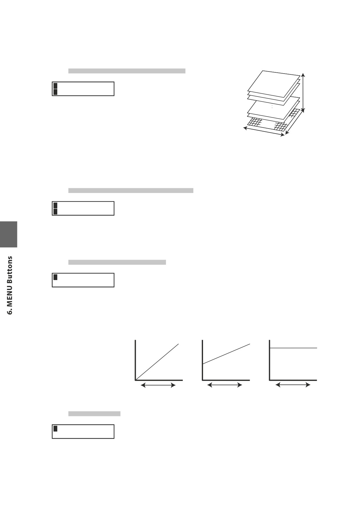
6.2.23 Bank MSB/LSB (Ext only)
This parameter determines which MSB and LSB
3ExternalMSB LSB
Bank LSB
Number will be transmitted when this SETUP
SBank =
000 032
0- 127
is recalled. When the MIDI Transmit Bank is set
to Off, this page will not be displayed.
In the MIDI standard, there are 128 storage
Bank MSB
spaces. The number of storage spaces can be
0- 127
expanded using an MSB and an LSB.
Program Number
0 - 127
This is a 3D image of the expanded program change system with the MSB and
LSB. To use these efficiently and correctly, refer to the operation manual of any
external MIDI sound modules that are connected to the MP6.
6.2.24 Keyboard On/Off (Ext only)
This parameter determines whether or not note data generated by playing the
3External
keys on the MP6 will be transmitted to an external MIDI device. This parameter is
SKeyboard
= On
useful when using 2 or more keyboards. When set to OFF the MP6 will not send
any note data to an external MIDI device but the MP6 can still be used to adjust
other connected keyboards or MIDI devices using the knobs, wheels etc.
6.2.25 Velocity Dynamics
This parameter allows the velocity dynamics of the selected zone to be adjusted
1 Concert Grand
Dynamics
= 10
relative to the Touch setting in th SYSTEM menu.
When this value is 10 (default), the keyboard response is normal (i.e. the same as
the Touch setting in the SYSTEM menu).
When this value is decreased the keyboard response gradually becomes less
dynamic, and at 0 becomes completely flat (i.e. fixed touch response).
Dynamics = 10
Dynamics = 5
Dynamics = 0
Volume
Volume
Volume
Level
Level
Level
0
127
0
127
0
127
Softer
Harder
Softer
Harder
Softer
Harder
Strength of the
Strength of the
Strength of the
struck key
struck key
struck key
6.2.26 Solo
This parameter turns the Solo Mode On/Off.
1 Concert Grand
Solo
= On
When Solo is turned “On” only one note will be heard for the selected zone
even if more than one note is being played simultaneously. This can be used
to effectively simulate the performance characteristics of a monophonic
synthesizer or as a special performance tool for playing solo parts. Solo mode
can also be used while playing a polyphonic part from another zone.
40
6.2.27 Solo Mode
This parameter determines which note will be played when Solo is ON and more
1 Concert Grand
Solo Mode
=Last
than one note is being played simultaneously. There are three choices for Solo
note priority.
Last
The most recently played note within a group of notes will be heard when
Solo is ON
Hi
The highest note played within a group of notes will be heard when Solo
is ON.
Low
The lowest note played within a group of notes will be heard when Solo is
ON.
* When the Solo Mode parameter is “Off”, this page will not be displayed.
6.2.28 Damper
This parameter determines if the damper pedal is active (Norm [Int] / On [Ext],
1 Concert Grand
Damper
= On
with natural decay), deactivated (Off) or set to HOLD (On, with steady sustain
level) for the selected zone.
Use the HOLD value, if you don’t want a sound to disappear. HOLD is only
available for internal Sounds.
6.2.29 Foot Switch
This parameter determines if a Foot Switch connected to the FOOT SWITCH jack
1 Concert Grand
Foot SW
= On
is active (On) or not (Off) for the selected zone. The type of controller assigned
to the footswitch is a common Setup parameter and is used for all zones of a
Setup as a global parameter.
6.2.30 Expression Pedal
This parameter determines if an Expression Pedal connected to the EXP jack is
1 Concert Grand
Exp Pedal
= On
active (On) or not (Off) for the selected zone. The type of controller assigned to
Expression pedal is a common Setup parameter and is used for all zones of a
Setup as a global parameter.
6.2.31 Modulation
This parameter determines if the Modulation Wheel is active (On) or not (Off) for
1 Concert Grand
Modulation = On
the selected zone.
* When the Tone Wheel sound is selected, this page will not be displayed.
41
6.2.32 Bender
This parameter determines if the Bender Wheel is active (On) or not (Off) for the
1 Concert Grand
Bender
= On
selected zone.
* When the Tone Wheel sound is selected, this page will not be displayed.
6.2.33 Bender Range
1 Concert Grand
Int
This sets the Bender Range in semitone steps. The value changes from 0 to 7.
Bendr Rng
=
2
Ext
This is used to transmit Bender Range information to external sound modules.
If MIDI Transmit Control Change is “On”, the value is transmitted when a SETUP
is recalled. The value changes from 0 to 12.
* When the Bender is “Off”, this page won’t be displayed.
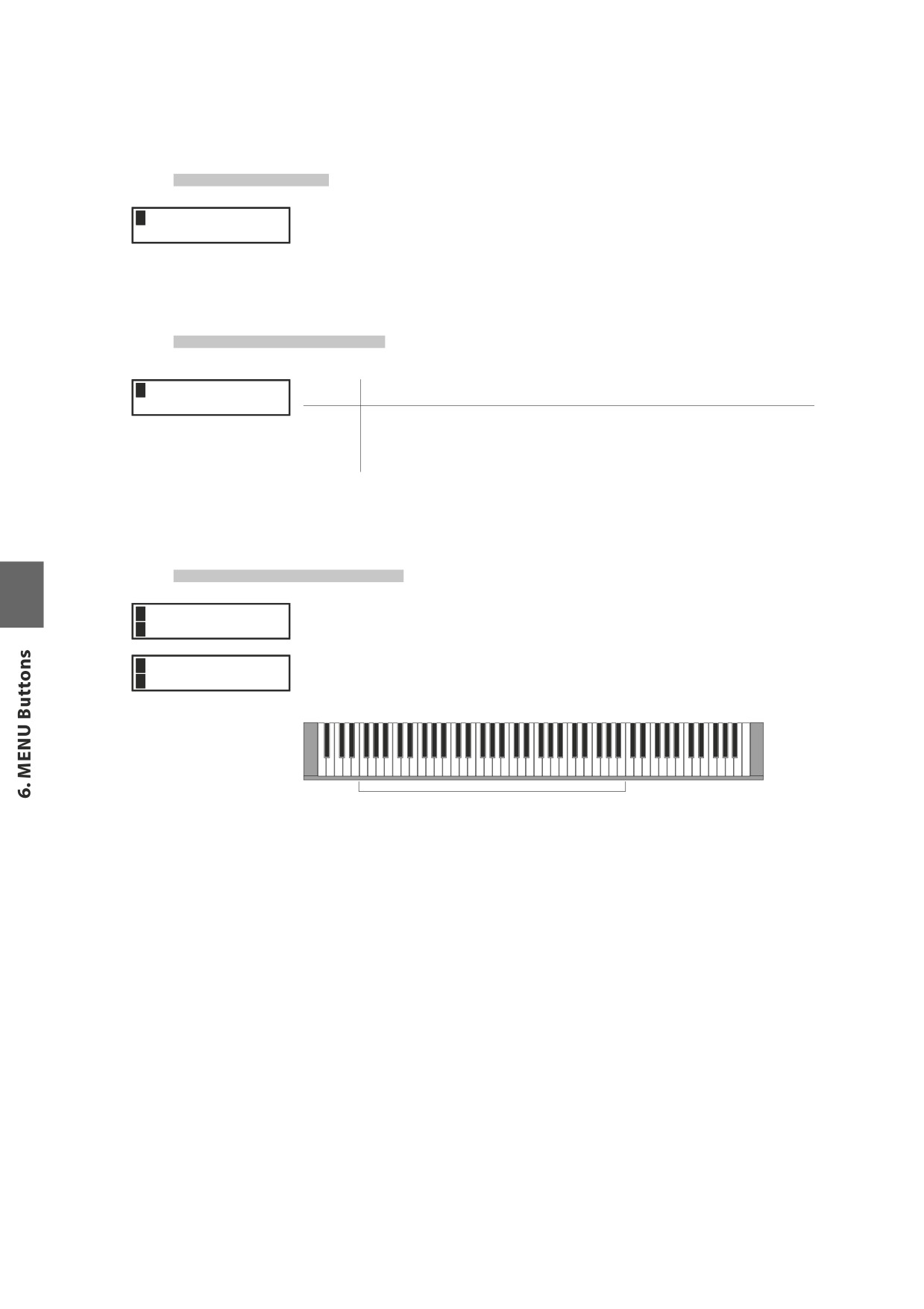
6.2.34 Key Range Hi/Lo
These two parameters define the playable key range on the keyboard for the
1 Concert Grand
selected zone. First, while K.Range Hi appears in the display, use the VALUE
SK.Range Hi= B4
buttons to set the highest note that the selected zone can play.
1 Concert Grand Next, while K.Range Lo appears in the display, use the VALUE buttons to set the
SK.Range Lo= F0
lowest note that the selected zone can play.
q
Playable Key Range
q
K. Range Lo
K. Range Hi
Note:
Another convenient way to input the key range is to hold the ZONE SELECT button
of the desired zone for more than 1 second and input the K.Range Lo by pressing
the lowest key followed by the key of the highest note, while still holding the
ZONE SELECT button.
42
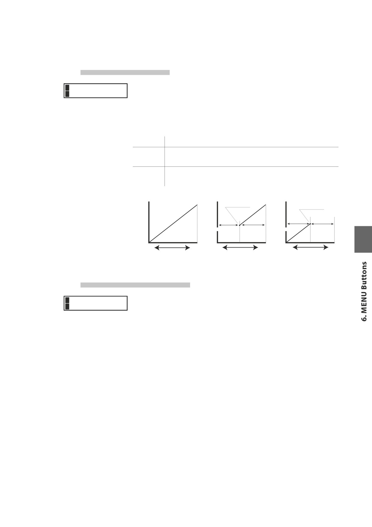
6.2.35 Velocity Switch
Velocity switching is an extremely useful and creative tool for customizing a
1 Concert Grand
SVel SW
=Loud
performance. Using Velocity Switching, it is possible to have either one sound
switch to another sound at a set velocity, or even for a second sound to be added
in once a certain velocity has been reached, or to have a sound drop out above
or below a set velocity level.
This parameter sets the velocity switch type.
Off
No effect - the sound plays normally.
Loud
The selected sound plays only when the key is struck harder than the Vel
SW Val. (See next parameter)
Soft
The selected sound plays only when the key is struck softer than the Vel
SW Val. (See next parameter)
Off
Loud
Soft
Vel SW val
Vel SW val
Volume
Volume
Volume
Level
Level
Level
Non-sound range
Sound range
Sound range
Non-sound range
0
127
0
127
0
127
Softer
Harder
Softer
Harder
Softer
Harder
Strength of the
Strength of the
Strength of the
struck key
struck key
struck key
6.2.36 Velocity Switch Value
This parameter determines switching level of the key velocity.
1 Concert Grand
SVel SW Val= 80
For the Loud Vel SW :determines the lowest key velocity to sound.
For the Soft Vel SW : determines the highest key velocity to sound.
When the Velocity Switch is set to Off, this page won’t be displayed.
Note:
Each zone can have a separate Velocity Switch Value. By setting the Soft Zone
Velocity Switch Value higher than that of the Loud Zone, a dynamic area where
both sounds play can be created. It is also possible to switch Internal Zones with
External Zones for even more possibilities.
Note2:
Velocity Switch = Loud /Velocity Switch Value = 1
In this settings, it is possible to press a key very softly and hear no sound.
This is just the same as an acoustic piano.
43
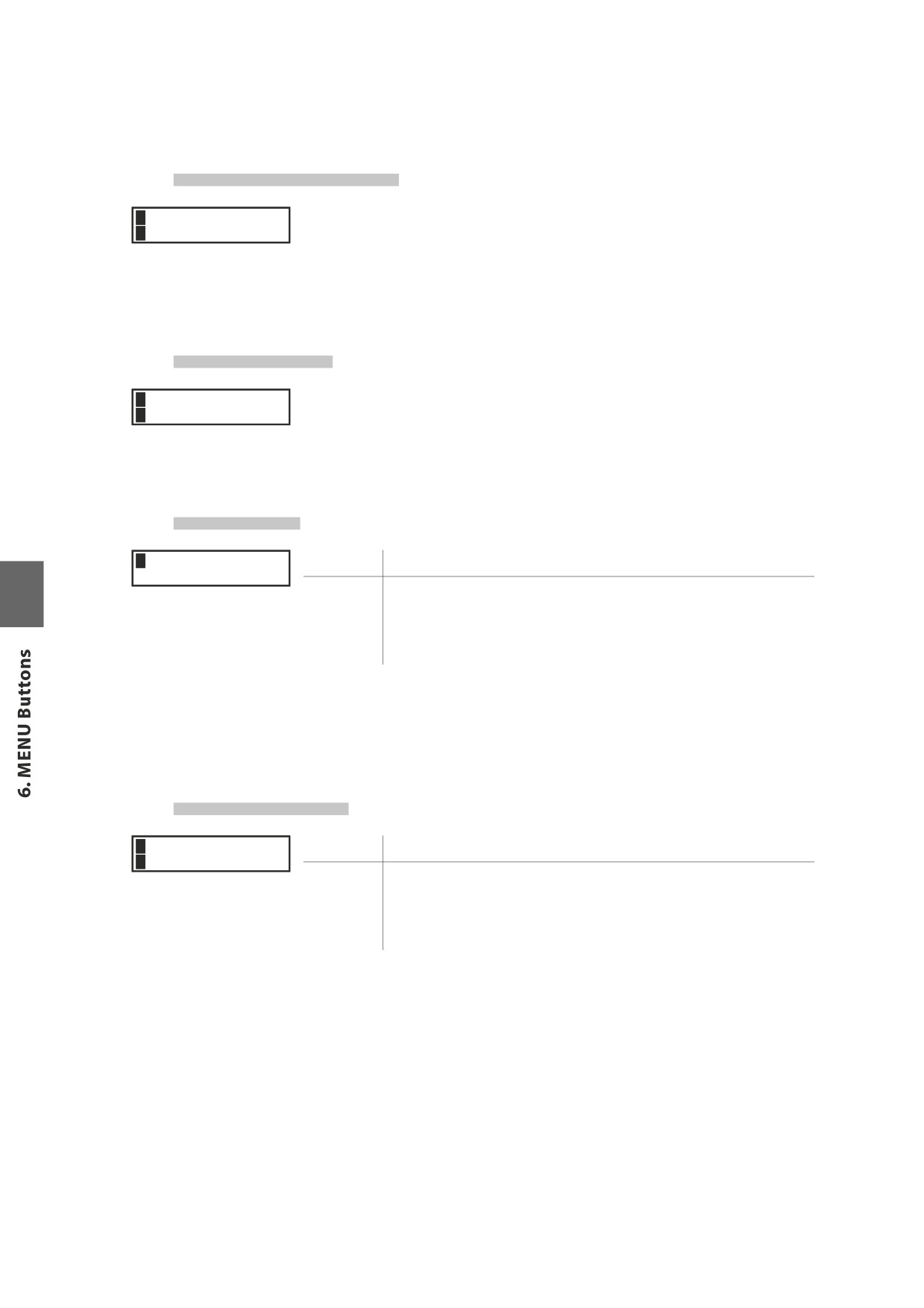
6.2.37 Zone Transpose
This parameter sets the amount of transposition for the selected zone. The
1 Concert Grand
SZone Trans=
0
available range is three octaves up or down (+/-36 semitones).
Note:
To set the master transpose, press the TRANSPOSE button and set the value.
6.2.38 Volume
This parameter sets the volume level for the selected zone. The value can be
1 Concert Grand
SVolume
= 127
changed by using the FADER or VALUE buttons.
For External zones, when the MIDI Transmit Control Change is “Off”, this page
won’t be displayed.
6.2.39 Pan
1 Concert Grand
Int
This sets the pan-pot (right and left balance).
Pan
= R10
Ext
This sets the pan-pot value that will be transmitted to external sound
modules. If the MIDI Transmit Control Change is “On”, the value is
transmitted when a SETUP is recalled. When the MIDI Transmit Control
Change is “Off”, this page won’t be displayed.
* The value changes from L64 to R63.
* When the Tone Wheel sound is selected, this page will not be displayed.
6.2.40 Fine Tune
1 Concert Grand
Int
This is a fine tuning function for values smaller than a semi-tone.
SFine Tune=
0
Ext
This is used to transmit fine tuning settings to external sound modules. If
the MIDI Transmit Control Change is “On”, the value is transmitted when
a SETUP is recalled. When the MIDI Transmit Control Change is “Off”, this
page won’t be displayed.
* The value changes from -63 to +63.
44
6.3 Common Parameters
The following common parameters affect all Zones.
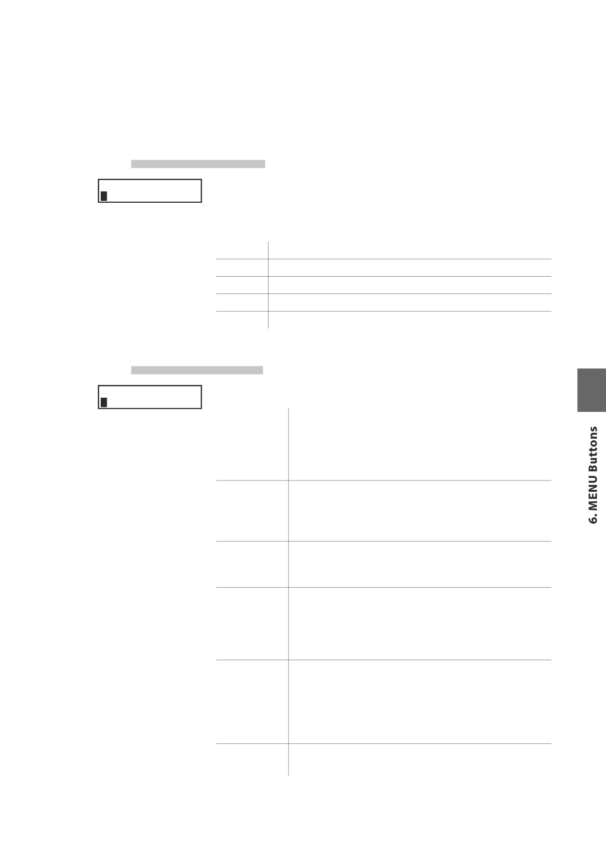
6.3.1 Stretch Tuning
COMMON
The hearing ability of a human is uneven and is not accurate with high frequency
SStrtch= Piano_w and low frequency as it is with the middle range. The tuning of an acoustic piano
is stretched to compensate for this so the sound will be heard naturally to the
ears.
Off:
The tuning is flat without stretching.
On:
The tuning is always stretched.
Piano:
The tuning is stretched only when piano sounds are selected.
On W:
Same as “On” but the stretching is wider.
Piano W:
Same as “Piano” but the stretching is wider.
6.3.2 Temperament
COMMON
This parameter sets the temperament of the MP6.
STempr =Pure
Maj
Equal
This is the most popular tuning method that divides the scale into
twelve equal semitones. This produces the same chordal intervals
in all twelve keys, and has the advantage of limitless modulation of
the key. However the tonality of each key becomes less characteristic
and no chord is in pure consonance.
Pure Maj/Min
This temperament, which eliminates dissonances for thirds and
fifths is still popular for choral music because of its perfect harmony.
When playing in a major key select “Pure Maj” and when playing in
a minor key select “Pure Min”.
Pythagor
This temperament, which uses mathematical ratios to eliminate
dissonance for fifths, is very limited for use with chords, but it
produces very characteristic melodic lines.
This temperament, which uses a mean between a major and minor
Meantone
whole tone to eliminate dissonance for thirds, was devised to
eliminate the lack of consonances experienced with certain fifths
for the Mersenne pure temperament. It produces chords that are
more beautiful than those with the equal temperament.
Werkmeis /
These two temperaments are placed in between Meantone and
Kirnberg
Pythagorean. For music with few accidentals, this temperament
produces the beautiful chords of the mean tone, but as accidentals
increase, the temperament produces the characteristic melodies of
the Pythagorean temperament. It is used primarily for classical music
written in the Baroque era to revive the original characteristics.
User
You can make your own temperament by raising or lowering the
pitch for each half tone.
45
6.3.3 Key of Temperament
Limitless modulation of the key became available only after the invention of Equal
COMMON
TemprKey = C
temperament. When we use a temperament other than Equal temperament, we
must carefully choose the key signature to play in.
For example, if the song you are going to play is written in D major, choose “D”
as the temperament key.
* When Temperament is set to Equal or User, this page won’t be displayed.
6.3.4 User Tuning
When the temperament is set to “User”, adjust the pitch for each key and create
COMMON
C
=
0
your own temperament. The value changes from -50 to +50.
These pages will only be displayed when the user temperament is selected.
Note:
The value is shown in “cent”. Half tone equals to 100 cents.
6.3.5 Foot SW CC# (Control Change)
This parameter assigns a Control Change Number to the Footswitch connected
COMMON
to the FOOT SWITCH jack on the rear panel.
FootSW CC# = SST
See page 96 for the list of Control Change numbers.
If “SW” is selected, the footswitch is used to turn on/off the SW button.
If
“RTR” is selected, the footswitch is used to switch the speed of the rotary
speaker between slow and fast when the Rotary effect is in use.
If
“AMP” is selected, the footswitch is used to turn the AMP simulator on/off.
When the System parameter FootSW is “Setup+” this page won’t be displayed.
6.3.6 EXP CC# (Control Change)
This parameter assigns a Control Change Number to the Expression Pedal
COMMON
connected to the EXP jack on the rear panel.
ExpPdl CC# = EXP
See page 96 for the list of Control Change numbers.
If “AFT” is selected, the expression pedal is used to send After Touch information.
If “RTR” is selected, the expression pedal is used to switch the speed of the rotary
speaker between slow and fast when the Rotary effect is in use.
If “AMP” is selected, the expression pedal is used to turn the AMP simulator on/off.
If “Pedal Wah” is selected in EFX, the pedal works as a Wah Pedal regardless of
the setting in this parameter.
46
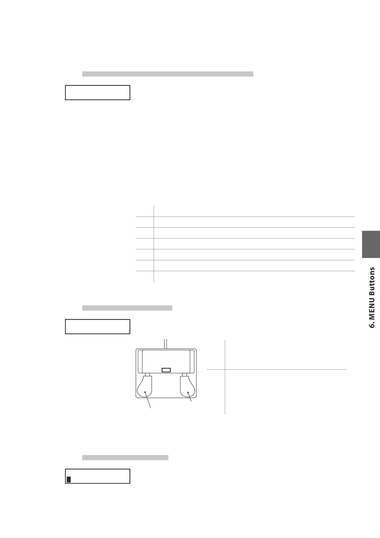
6.3.7 Modulation Wheel CC# (Control Change)
This parameter assigns a Control Change Number to the Modulation Wheel on
COMMON
M.WheelCC# = Mod
the right side of the front panel.
If “AFT” is selected, the modulation wheel is used to send After Touch information.
If “RTR” is selected, the modulation wheel is used to switch the speed of the
rotary speaker between slow and fast when the Rotary effect is in use.
If “AMP” is selected, the modulation wheel is used to turn the AMP simulator
on/off.
See page 96 for the list of Control Change numbers.
Note:
When the following Numbers are selected for the FootSW,EXP or Modulation
Wheel Control Change Number, the functions affect the internal sounds, too.
1
Modulation Wheel (MOD)
7
Volume (VOL)
10
Pan (PAN)
11
Expression Controller (EXP)
64
Damper Pedal (HLD)
66
Sostenuto (SST)
67
Soft Pedal (SFT)
6.3.8 Left Pedal Mode
This parameter determines whether the left pedal of the optional F-20 (twin
COMMON
Left Pedal =Soft pedal) accessory functions as Soft or Sost (Sostenuto).
Soft
The Left Pedal works as a Soft Pedal ( Default ).
When the Rotary EFX is in use, the Soft Pedal
changes function to a Fast/Slow Rotor switch.
Sost
The Left Pedal works as a Sostenuto Pedal.
When the Damper setting (see page 41) is Off or
Norm, the sostenuto pedal works with natural
decay. When the Damper setting is Hold, the
Right Pedal
Left Pedal
(FSW)
sostenuto pedal works with a steady sustain level.
F-20
6.3.9 Master Volume
Adjust the total volume of the SETUP.
COMMON
SMaster Vol= 127
The value changes from 0 to 127.
47
7. Song Recorder (Internal Memory)
The MP6 allows up to 10 different songs to be recorded, stored in internal
memory, and played back at the touch of a button.
7.1 Recording a song
7.1.1 Entering song recorder mode
Press the RECORDER button.
Type = MIDI
[REC]or[PLAY]
The type (MIDI/AUDIO/SMF) selection screen will be shown in the LCD display.
Press the VALUE d button to change the type to MIDI, then press the z button.
1:INT SONG 1
œ=120
The Internal Song Recorder screen will be shown in the LCD display, and the LED
indicator for the z button will start to flash.
The MP6 recorder will enter standby mode.
Press the __ or `` buttons to select the song memory for the recording, and
the VALUE buttons to increase or decrease the tempo.
The MP6 recorder will enter standby mode.
7.1.2 Starting the song recorder
Press a key on the keyboard.
The LED indicators for the z and f/ buttons will turn on, and recording will
start.
* Recording can also be started by pressing the f/ button.
* If the METRONOME is turned on before recording, a one bar introduction will
also be played when the f/ button is pressed.
7.1.3 Stopping the song recorder
Press the f/ button.
The LED indicators for the z and f/ buttons will turn off, the recorder will
stop, and the recorded song will be stored in internal memory.
After a few seconds, the Play Internal screen will be shown in the LCD display,
indicating that the song is ready for playback.
* The maximum recording capacity is approximately 90,000 notes, with button
and pedal presses also counted as one note.
* If the maximum recording capacity is reached during recording, the recorder
will stop automatically.
* Recorder songs will remain in memory after the power is turned off.
48
7.2 Playing back a song
7.2.1 Entering song play mode
Press the RECORDER button.
Type = MIDI
[REC]or[PLAY]
The type (MIDI/AUDIO/SMF) selection screen will be shown in the LCD display.
Press the VALUE d button to change the type to MIDI, then press the f/ button.
1:INT SONG 1
œ=120
The Internal Song recorder screen will be shown in the LCD display.
Press the
__ or `` buttons to select the song memory to playback, and the
VALUE buttons to increase or decrease the tempo.
7.2.2 Starting the song playback
Press the f/ button.
The selected song will start to play.
* Press and hold the f/ button to play all recorder songs in sequence (‘Chain
Play’ mode).
Press the __ or `` buttons to fast-forward or rewind the song.
Press the f/ button again.
The selected song will stop playing.
It is also possible to adjust the Song Volume, Song Transpose or Song Memory.
Press the MENU d or MENU c buttons to select the desired function, then press
the VALUE d or VALUE c buttons to adjust the value.
* Press the e button to reset the recorder song to the beginning.
7.2.3 A-B Repeat
The A-B repeat function allows one section of a song to be repeated continuously.
While the song is playing:
Press the AB button to set the start point.
The LED indicator for the AB button will start to flash.
Press the AB button again to set the end point.
The LED indicator for the AB button will turn on and the specified section
will repeat continuously.
To cancel the A-B repeat function, press the AB button once again.
The LED indicator for the AB button will turn off and normal playing will
resume.
49
7.2.4 Exiting song play mode
Press the RECORDER button to exit the Internal Song Recorder.
The MP6 will return to normal operation, and the name of the selected sound
will be shown in the LCD display.
7.3 Erasing a song
This function is used to erase recorder songs that have been recorded incorrectly,
or are simply no longer required.
7.3.1 Entering erase mode
Press the RECORDER button.
Type = MIDI
[REC]or[PLAY]
The type (MIDI/AUDIO/SMF) selection screen will be shown in the LCD display.
Press the VALUE d button to change the type to MIDI, then press the f/ button.
1:INT SONG 1
œ=120
The Internal Song Recorder screen will be shown in the LCD display.
Press and hold the z and f/ buttons simultaneously.
The LED indicators for the z and f/ buttons will start to flash, and the Erase
Erase
≥
Song 1
screen will appear with the currently selected song shown in the LCD display.
7.3.2 Erasing a song
Press the __ or `` buttons to select the Song to be erased.
Erase
≥
Song 1
Press the VALUE c button.
A confirmation message will be shown in the LCD display, prompting to confirm
or cancel the erase operation.
Press the VALUE c button once again to confirm the erase operation,
Sure?
≥
Song 1
or the VALUE d button to cancel the erase operation.
Erasing all recorder songs from memory
This process will erase all songs stored in
internal memory, and cannot be undone.
Press and hold the z and f/ buttons simultaneously, then turn the power on.
All recorder songs stored in memory will be erased.
50
8. Audio Recorder/SMF Player (USB Memory)
The MP6 is also capable of recording performances directly to a USB memory
device as MP3 or WAV digital audio. This function allows professional quality
recordings to be produced directly on the instrument - without the need for
additional sound equipment.
The MP6 can also playback Standard MIDI Files (SMF) from a USB memory device.
8.1 Recording an audio file
Audio Recorder format specifications
MP3
44.1kHz, 16 bit, Stereo 192kbit/s (fixed)
WAV
44.1kHz, 16 bit, Stereo
* MPEG Layer-3 audio coding technology licensed from Fraunhofer IIS and Thomson.
* MP3 codec is Copyright (c) 1995-2007, SPIRIT
* USB devices should be formatted to use the ‘FAT’ or ‘FAT32’ filesystems.
8.1.1 Entering audio recorder mode
Connect a USB memory device to the MP6.
Press the RECORDER button.
Type = AUDIO
[REC]or[PLAY]
The type (MIDI/AUDIO/SMF) selection screen will be shown in the LCD display.
Press the VALUE c button to change the type to AUDIO, then press the z button.
Recording
Format = MP3
The Audio Recorder format selection screen will be shown in the LCD display,
and the LED indicator for the z button will start to flash.
Press the VALUE c VALUE d buttons to select the MP3 or WAV audio format.
8.1.2 Starting the audio recorder
Press a key on the keyboard.
Audio_001
MP3
0'00"
The LED indicators for the z and f/ buttons will turn on, and the Audio
Recorder will start recording audio in the file format specified.
* Recording can also be started by pressing the f/ button.
* If the METRONOME is turned on before recording, a one bar introduction will
also be played when the f/ button is pressed.
* The default filename for recorded audio is Audio_000. If the file already exists
on the connected USB memory device, the filename number will increment
automatically. To change the name of the recorded file, use the Rename
function in the USB menu (page 70).
8.1.3 Stopping the audio recorder
Press the f/ button again.
The LED indicator for the f/ button will turn off and the the Audio Recorder
will stop recording.
After a brief wait, the Audio Player screen will be shown in the LCD display.
Audio_001
MP3
0'00" VOL= 60
51

8.2 Playing an audio file
Audio Player supported format specifications
MP3
32/44.1/48 kHz, Mono/Stereo, 8-320 kbit/s (fixed & variable)
WAV
32/44.1/48 kHz, Mono/Stereo, 16 bit
* USB devices should be formatted to use the ‘FAT’ or ‘FAT32’ filesystems.
8.2.1 Entering audio playback mode
Connect a USB memory device to the MP6.
Press the RECORDER button.
Type = AUDIO
[REC]or[PLAY]
The type (MIDI/AUDIO/SMF) selection screen will be shown in the LCD display.
Press the VALUE c button to change the type to AUDIO, then press the f/
>Get Back
MP3
Hold On
MP3
button.
The file load screen will be shown in the LCD display.
8.2.2 Selecting an audio file
Press the VALUE c or VALUE d buttons to move the selection arrow.
>Hold On
MP3
I Got You MP3
File selection screen examples:
[Parent Dir
]
Return to previous folder
<Classical
>
Folder
Audio_001 MP3
File (MP3 format)
Audio_002 WAV
File (WAV format)
8.2.3 Starting audio file playback
Press the f/ button.
Hold On
MP3
0'00" VOL= 60
The LED indicator for the f/ button will turn on and the selected audio file
will start to play.
* Press and hold the f/ button to play all MP3/WAV audio files stored in the
current folder in sequence (‘Chain Play’ mode).
Press the __ or `` buttons to fast-forward or rewind the song, and the VALUE
buttons to increase or decrease the playback volume.
Finally, press the f/ button again to stop audio file playback.
To return to the file load screen, press the MENU c or MENU d buttons.
8.2.4 Exiting audio recorder mode
Press the RECORDER button to exit the Audio Recorder.
The MP6 will return to normal operation, and the name of the selected sound
will be shown in the LCD display.
52
8.3 Playing a Standard MIDI file
SMF Player supported format specifications
MID
Format 0, Format 1
* USB devices should be formatted to use the ‘FAT’ or ‘FAT32’ filesystems.
* The program change recognition is based on the Program Number List,
with Program Change Mode=GM type. (see page 79)
*The MP6 is not a GM device, therefore some sounds that the MP6 does not recognize
may be replaced by similar sounds that are available.
8.3.1 Entering SMF playback mode
Connect a USB memory device to the MP6.
Press the RECORDER button.
Type = SMF
Press [PLAY]
The type (MIDI/AUDIO/SMF) selection screen will be shown in the LCD display.
Press the VALUE d button to change the type to SMF, then press the f/
>Don't Worry MID
Move On Up
MID
button.
The file load screen will be shown in the LCD display.
8.3.2 Selecting a Standard MIDI File
Press the VALUE c or VALUE d buttons to move the selection arrow.
>Move On Up MID
Superfly
MID
File selection screen examples:
[Parent Dir
]
Return to previous folder
<Classical
>
Folder
MIDI_001 MID
Standard MIDI File (MID format)
8.3.3 Starting Standard MIDI File playback
Press the f/ button.
Move On Up.MID
1-1
œ=120
The LED indicator for the f/ button will turn on and the selected Standard
MIDI File will start to play.
* Press and hold the f/ button to play all Standard MIDI Files stored in the
current folder in sequence (‘Chain Play’ mode).
Press the __ or `` buttons to fast-forward or rewind the song, and the VALUE
buttons to increase or decrease the playback volume.
Finally, press the f/ button again to stop SMF playback.
* Press the e button to reset the Standard MIDI File to the beginning.
To return to the file load screen, press the e button, then press the __ or ``
buttons.
53
8.3.4 Adjusting SMF volume, Transposing the SMF, Minus One
After the SMF has been selected, or while the SMF is playing:
Press the MENU d or MENU c buttons to select the desired SMF Menu function,
then press the VALUE d or VALUE c buttons to adjust the value.
SMF Volume
0 - 127
SMF Transpose
- 24 - +24 (semitones)
Minue One Part
Off, 1-16 (MIDI channel)
8.3.5 Exiting SMF playback mode
Press the RECORDER button to exit the SMF Player.
The MP6 will return to normal operation, and the name of the selected sound
will be shown in the LCD display.
54
9. STORE Button
You can save the changes of the settings made as either a SOUND or a SETUP.
Up to 256 SOUNDs or 256 SETUPs can be stored.
Moreover, the POWER ON function allows preferred panel setting to be stored
in the instrument's memory, and automatically recalled as the settings every
time the MP6 is turned on.
The following groups of parameters are stored:
SOUND
Selected Zone’s One Sound settings:
* EFX/REVERB settings (see page 26)
* Control Knob settings - except for EQ (see page 28)
* Int Zone parameters in MENU settings (see page 34)
- except for parameters with the inverse “S(Setup)” icon
SETUP
MP6’s whole settings of 4 zones:
* Sound Selection, Zone On/Off Status (see page 10)
* EFX/REVERB settings (see page 26)
* Fader, Control Knob settings (see page 10, page 28)
* Function SW setting (see page 22)
* All MENU settings (see page 34)
* Metronome settings (see page 18)
9.1 Storing the settings as a SOUND
Press the STORE button. The display will show the following screen:
<SETUP
SOUND>
<POWERON
Press the VALUE c button, the display will show the following screen:
SOUND
Sure?
Press VALUE UP
Press the VALUE c button to confirm. The STORE procedure can be cancelled
at any time by pressing any other button which is not used during the STORE
procedure.
Writing Memory,
Completed!
Note:
Storing will overwrite the selected SOUND.
If the selected zone is external, the SOUND cannot be stored.
55
9.2 Storing the settings as a SETUP
Press the STORE button. The display will show the following screen:
<SETUP
SOUND>
<POWERON
Press the MENU c button to select to store the settings as a SETUP.
The display will show the SETUP number to store.
Store to 1-1-A
= GrandPno+Str1
Use the SOUND SELECT buttons to change the SETUP number in which the
settings will be stored. For example, to choose SETUP 2-3-B, press 2 in the upper
row, press 3 in the second row, and press B in the third row. Then press the
STORE button.
Name
≥[STORE]
=GrandPno+Str1
To set a name use the MENU buttons to move the cursor, use the VALUE buttons
to select the character. After you rename the SETUP, press the STORE button
again.
Are You sure?
Press VALUE UP
Press the VALUE c button to confirm. The STORE procedure can be cancelled
at any time by pressing any other button which is not used during the STORE
procedure
Writing Memory,
Completed!
Note:
Storing will overwrite the selected SETUP.
56
9.3 Storing the POWER ON setting
Press the STORE button. The display will show the following screen:
<SETUP
SOUND>
<POWERON
Press the MENU d button, the display will show the following screen:
POWERON Sure?
Press VALUE UP
Press the VALUE c button to confirm. The STORE procedure can be cancelled
at any time by pressing any other button which is not used during the STORE
procedure.
Writing Memory,
Completed!
57
10. SYSTEM Button
Use this mode to set the System parameters of MP6.
To enter the SYSTEM mode, press the SYSTEM button.
10.1 System Menu
Use the MENU buttons to scroll through the System parameters.
System Parameter
System Channel
Touch
System Tuning
Volume Slider Action
Reverb Offset
EQ Offset
Local Control On/Off
Program Change Mode
MIDI Receive Mode
MIDI Receive Channel
MIDI Transmit SETUP Mode
MIDI Transmit Program Change
MIDI Transmit Bank
MIDI Transmit Volume
MIDI Transmit Control Change
MIDI Transmit Recorder
MMC On/Off
MMC Assign
MMC Device ID
LCD Contrast
LED Brightness
Out Mode
Foot Switch Mode
Wheel Mode
System Reset
Reset One Sound/Setup
Reset All
Make sure the SYSTEM button is lit, then press the MENU buttons until the
parameter you wish to edit appears in the display.
Set the value of the parameter by using the VALUE buttons.
The value range differs depending on the parameter.
10.2 System Parameters
The System Menu parameters are global and always stored automatically when
leaving the SYSTEM mode, so there is no need to store them.
10.2.1 System Channel
This parameter sets the System MIDI channel on which System Exclusive
SYSTEM
System Ch
=
1
messages are transmitted/received.
58
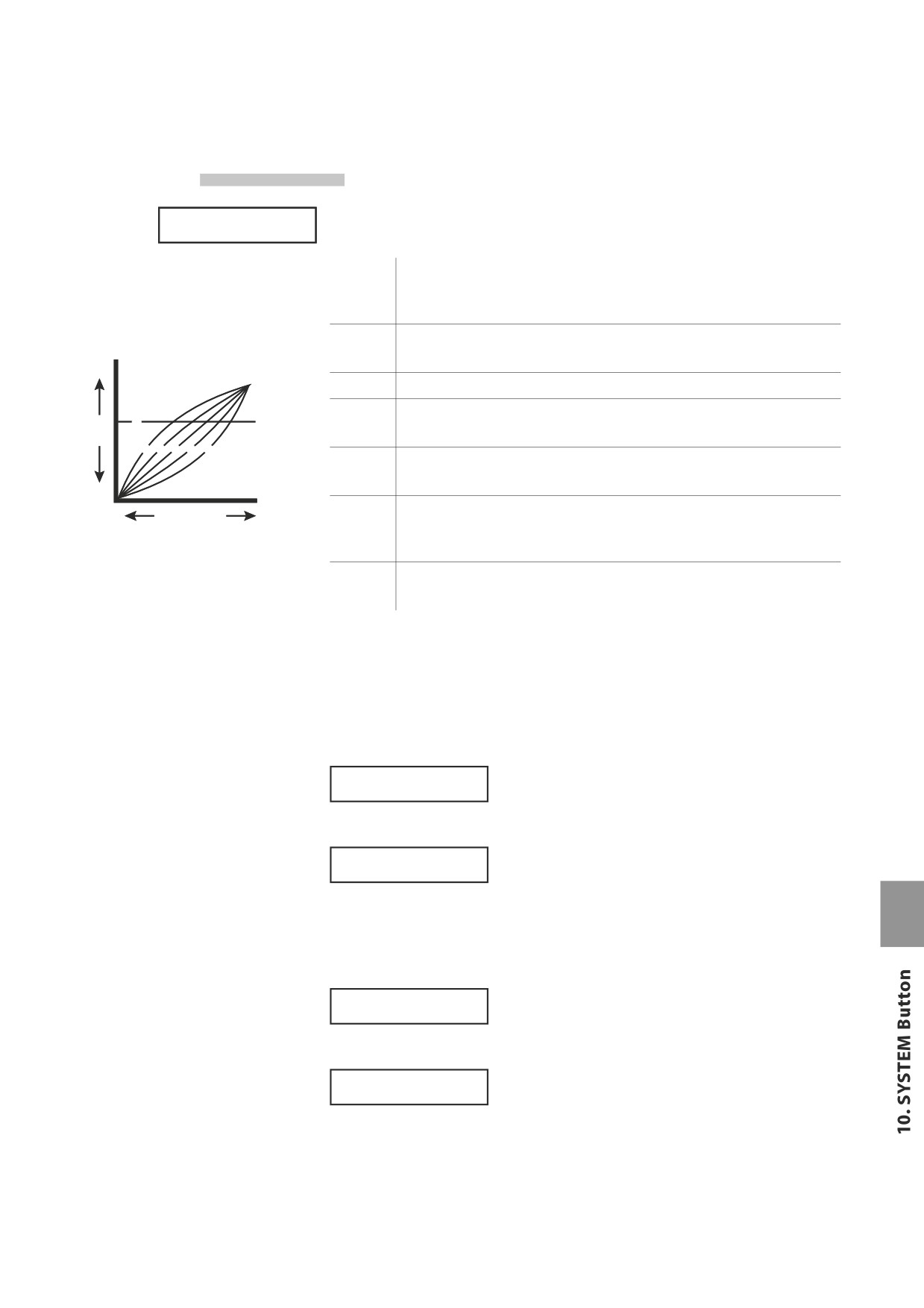
10.2.2 Touch
This parameter adjusts the touch response curve of the keyboard.
SYSTEM
Touch = Normal
Heavy+
This Curve has a steep rise as velocity increases, and a shallower curve at
low velocities. (see 1) This curve requires the most striking force to produce
a loud volume.
Heavy
This curve requires a stronger striking force to produce a loud volume. (see
2) This curve is perfect for those with strong fingers.
Louder
Normal
This curve recreates the touch response of an average acoustic piano.
Light
This curve requires less striking force to produce a loud volume. (see 4) This
Volume
f
level
curve is good for those still developing finger strength.
e d c b a
Light+
This curve requires the least amount of striking force to produce a loud
volume. (see 5) This curve is good for those with a very delicate touch.
Softer
Softer
Strength of
Harder
Off
This curve gives a constant velocity level no matter how hard the keyboard
the struck key
is struck. (see 6) This curve is suitable for sounds that have a fixed dynamic
range such as Organ, Harpsichord and certain synthesizer sounds.
a Heavy+
d Light
b Heavy
e Light+
User1,2
You can create your own custom touch curve to fit your playing style. Two
c Normal
f Off
user touch curves can be saved.
User Touch
The touch curve is the main component between the action and the sound.
With this User Touch Curve function you can customize the MP6 according to
your personal playing style.
After selecting the “Touch” function by pressing the MENU buttons, use the
VALUE buttons to select User1 or User2. Now the selected curve is activated.
Press REC
Touch = User 1
To create your own personal touch curve press the REC button.
Start playing
Soft ≥ Loud
Now start playing the piano dynamically from soft to loud in order to let the
piano analyze your playing style. Make sure that you really play in a realistic way
according to your finger power and feeling. Sometimes the result is better if you
turn off the volume first.
Press REC
when finished
Press the REC button again when you finish playing.
Analysis
Completed!!
The piano will analyze your playing and create a custom touch curve for you
based upon your playing style. The new curve is automatically saved and will be
used until you change the touch curve again or record a new one.
59
10.2.3 System Tuning
This parameter sets the global master tuning of the MP6. The value changes
SYSTEM
SysTune
= 440.0
from 427.0 to 453.0 (Hz).
10.2.4 Volume Slider Action
This parameter sets how the volume sliders react, when you change the volume.
SYSTEM
VolAction=Catch
Normal
The value changes immediately, when the volume slider is moved.
Catch
The value won’t change until the volume slider catches the position
of the previously saved Volume value. This setting is designed for
live editing to prevent you from unexpected volume jumps.
10.2.5 Reverb Offset
This parameter sets the global reverb depth offset. The value changes from 0 to
SYSTEM
Rev.Offset =100%
100%. You can decrease the whole depth of the MP6.
10.2.6 EQ Offset On/Off
This parameter sets the global EQ.
SYSTEM
EQ Offset
= On
On
The global EQ settings are added to the EQ knob settings.
Off
The global EQ is disabled.
10.2.7 EQ Offset
This parameter sets the global EQ offset value of the MP6. The value changes
SYSTEM
EQ High
=
0
from -9 to +9 (dB).
These parameters - High, Mid and Low - are each added to the EQ knob
SYSTEM
EQ Mid
=
0
settings.
In the case that the total value exceeds +-9dB, it is limited to +-9dB.
SYSTEM
EQ Low
=
0
When the EQ Offset On/Off is set to Off, this page won’t be displayed
60
10.2.8 Local Control
SYSTEM
On
The keyboard of the MP6 and the internal tone generators are
Local
= On
connected. Set this parameter to “On” for normal use.
Off
The internal connection between the keyboard and the tone
generators is switched off. This feature will avoid the “Doubled
Sound” that results from use with an external sequencer equipped
with Soft Thru or Echo Thru.
10.2.9 Program Change Mode
This parameter determines the sound numbering format that is used when
SYSTEM
Prg Mode =Panel
sending MIDI Program Change information.
Panel
Program Change data is sent in accordance with the instrument’s
panel button numbering format.
GM
Program Change data is sent in accordance with the standard GM
numbering format.
Select this setting when connecting the MP6 to GM devices.
10.2.10 MIDI Receive Mode
This parameter determines how the MP6 receives MIDI information.
SYSTEM
Rcv Mode =Panel
Panel
Only MIDI information received from the designated system
channel will be sent to Zone 1-4 (Int. only).
With this setting, layer and internal effects will be available.
Multi
MIDI information received from all MIDI channels (1-16) will be sent
to Zone 1-4 or MIDI channels.
With this setting, the MIDI Receive Ch. (10.2.11) can also be specified.
Omni
Received data controls the whole panel, regardless of the MIDI
channel.
61
10.2.11 MIDI Receive Channel
When the MIDI Receive Mode setting (10.2.10) is set to ‘Multi’, this parameter
SYSTEM
Rcv Ch 1 =Zone1
determines whether the receive channel is On, Off, or specific to an individual
Zone.
Zone1-4
Send MIDI data to specified Zone.
On
Specified channel will receive MIDI data.
Off
Specified channel will NOT receive MIDI data.
Note:
* This parameter will only be displayed when MIDI Recieve Mode (10.2.10) is set to ‘Multi’.
* Rcv Ch can be set to channels 1-16.
10.2.12 MIDI Transmit SETUP Mode
This parameter determines whether MIDI information is sent when selecting
SYSTEM
Trs.Setup
=Off
SETUPs
On
MIDI information is sent when selecting SETUPs.
Off
MIDI information is NOT sent when selecting SETUPs.
10.2.13 MIDI Transmit Program Change
When the MIDI Transmit SETUP Mode setting (10.2.12) is set to ‘On’, this
SYSTEM
Set Program =On
parameter determines whether MIDI Program Change information is sent when
selecting SETUPs.
On
MIDI Program Change information is sent when selecting SETUPs.
Off
MIDI Program Change information is NOT sent when selecting SETUPs.
Note:
* This parameter will only be displayed when MIDI Transmit SETUP Mode (10.2.12) is set to ‘On’.
10.2.14 MIDI Transmit Bank
When the MIDI Transmit SETUP Mode setting (10.2.12) is set to ‘On’, this
SYSTEM
Set Bank
=On
parameter determines whether MIDI Bank information is sent when selecting
SETUPs.
On
MIDI Bank information is sent when selecting SETUPs.
Off
MIDI Bank information is NOT sent when selecting SETUPs.
Note:
* This parameter will only be displayed when MIDI Transmit SETUP Mode (10.2.12) is set to ‘On’.
62
10.2.15 MIDI Transmit Volume
When the MIDI Transmit SETUP Mode setting (10.2.12) is set to ‘On’, this
SYSTEM
Set Volume
=On
parameter determines whether MIDI Volume information is sent when
selecting SETUPs.
On
MIDI Volume information is sent when selecting SETUPs.
Off
MIDI Volume information is NOT sent when selecting SETUPs.
Note:
* This parameter will only be displayed when MIDI Transmit SETUP Mode (10.2.12) is set to ‘On’.
10.2.16 MIDI Transmit Control Change
When the MIDI Transmit SETUP Mode setting (10.2.12) is set to ‘On’, this
SYSTEM
Set Control =On
parameter determines whether MIDI Control Change information is sent when
selecting SETUPs.
On
MIDI Control Change information is sent when selecting SETUPs.
Off
MIDI Control Change information is NOT sent when selecting SETUPs.
Note:
* This parameter will only be displayed when MIDI Transmit SETUP Mode (10.2.12) is set to ‘On’.
10.2.17 MIDI Transmit Recorder
This parameter determines whether MIDI information is sent when using the
SYSTEM
Trs.Recorder=On
Internal Song Recorder.
On
MIDI information is sent when using the Internal Song Recorder.
Off
MIDI information is NOT sent when using the Internal Song Recorder.
63
10.2.18 MMC On/Off
This parameter determines whether MMC (MIDI Machine Control) information is
SYSTEM
MMCtransport=On
sent when pressing the RECORDER CONTROL buttons.
On
MMC information is sent when using the RECORDER CONTROL buttons.
Off
MMC information is NOT sent when using the RECORDER CONTROL buttons.
10.2.19 MMC Assign
When the MMC setting (10.2.18) is set to ‘On’, this parameter determines which
SYSTEM
PLAY =Play
MMC commands are sent when pressing the RECORDER CONTROL buttons.
Button
MMC Command
PLAY/STOP
Play
Pause
Record Strobe
REC
Record Pause
Record Exit
RESET
Stop
FF
Fast Forward
Pause
REW
Rewind
Pause
LOOP
Deferred Play
Note:
* This parameter will only be displayed when MMC Transmit (10.2.18) is set to ‘On’.
10.2.20 MMC Device ID
This parameter determines the Device ID of the MMC (MIDI Machine Control).
SYSTEM
MMC Dev.ID = 127
10.2.21 LCD Contrast
This parameter adjusts the contrast of the LCD display.
SYSTEM
LCD Cont.
= 10
As the value changes higher, the contrast gets sharper. The value changes from
1 to 10.
64
10.2.22 LED Brightness
This adjusts the brightness of the LEDs. You can choose from High or Low.
SYSTEM
LED Bright.=High
The Low setting is designed for dark stages, while the High setting is good for
bright ambience.
10.2.23 Out Mode
Sometimes it is convenient to have two mono outputs instead of a stereo
SYSTEM
Out Mode =Stereo
output.
In this case one mono output can be used for your own monitor system and the
other goes to the mixing console.
Stereo
The signal on the Line-Outs is normal stereo.
2xMono
The signal on the Line-Outs is mono on both jacks
Note:
* To avoid unexpected sound issues some stereo effects like AutoPan will be turned off
when 2xMono is selected.
10.2.24 Foot Switch Mode
This parameter sets the mode of FootSW's function.
SYSTEM
FootSW
=Normal
Normal:
The type of controller assigned to the footswitch is a common SETUP
parameter "FootSW CC#". (see page 46)
Setup+:
The footswitch increments the selected SETUP by 1.
Plybck:
The footwitch starts/stop selected song (audio file etc.) playback.
Metro.:
The footswitch starts/stop selected metronome/rhythm pattern.
Note:
* When the value is ‘Setup+’, the FootSW CC# page will not be displayed.
65
10.2.25 Wheel Mode
This parameter determines whether or not the modulation wheel can be used
SYSTEM
WheelMode=Normal
to edit parameters like a value dial.
Normal:
The wheel functions as a performance wheel and controls the CC
controller that is assigned in the setup menu (Default).
The wheel is used to edit parameters. The value will not change
until the wheel reaches the position of the previously set the value.
It can be used to edit the following parameters:
Edit:
* SETUP parameters in the MENU except Zone mode and Sound
* SETUP name when stored
* Function SW assign, EFX/REVERB type
* Tempo of the metronome
Note:
* When the Wheel Mode is set to “Edit”, the normal function of the wheel is ineffective, and
the wheel parameters will show an asterisk.
1 Concert Grand
COMMON
Modulation =*On
M.WheelCC# =*Mod
66
10.3 System Reset
10.3.1 Reset One SOUND/SETUP
This function resets one SOUND or SETUP back to the original factory default
Reset 6-4-A
Press VALUE UP
settings.
Press the SYSTEM button. Then press the MENU d button until “Reset
X-X-X” (X-X-X stands for the setup number) appears on the display. Now use the
SOUND SELECT buttons to select the sound or setup you want to reset.
Press the VALUE c button. The display will ask for confirmation.
Reset 6-4-A
Sure?
To cancel the Reset procedure at this point, press the VALUE d button.
Otherwise, press the VALUE c button again.
The display will show “Completed!!” after finishing.
Reset 6-4-A
Completed!!
Note:
* The selected SOUND/SETUP data will be overwritten by the factory settings.
10.3.2 Reset All
This function performs a global reset of all 256 SOUNDs, all 256 SETUPs and
Reset All
Press VALUE UP SYSTEM settings back to the original factory default settings.
Press the SYSTEM button. Then press the MENU d button until “Reset All”
appears on the display.
Press the VALUE c button. The display will ask for confirmation.
Reset All
Sure?
To cancel Reset All at this point, press the VALUE d button.
Otherwise, press the VALUE c button again.
The display will show “Completed!!” after finishing.
Reset All
Completed!!
Note:
* All the data in the MP6 will be overwritten by the factory settings.
67
11. USB Button
The USB button contains functions to load and save sounds, setups, system settings, and songs from/to
a USB memory device. This menu also allows files to be renamed and deleted, and for the USB memory
device to be formatted.
Load
Load data stored on a USB memory device into the MP6’s internal memory.
Save
Save data held in the MP6’s internal memory to a USB memory device.
Rename
Rename a file stored on a USB memory device.
Delete
Delete a file stored on a USB memory device.
Format
Format a USB memory device, erasing all stored data.
Selecting the USB menu
First, connect a USB memory device to the USB to Device connector.
Press the USB button.
The USB menu will be shown in the LCD display.
Press the MENU c or MENU d buttons to select the desired USB function, then
1..Load
Press VALUE UP
press the VALUE c button to enter the menu.
File selection screen examples:
[Parent Dir
]
Return to previous folder
<Classical
>
Folder
Audio_001.MP3
File (MP3 format)
Audio_002.WAV
File (WAV format)
11.1 Load
11.1.1 Selecting Load
Follow the instructions above to select the Load function from the USB menu.
1..Load
Press VALUE UP
The USB Load menu will be shown in the LCD display.
<SETUP
SOUND>
<SYSTEM
SMF>
Press the MENU or VALUE buttons to select the desired USB Load function.
SETUP
Load SETUP data from a USB memory device.
SOUND
Load SOUND data from a USB memory device.
SYSTEM
Load SYSTEM data from a USB memory device.
SMF
Load SMF song data from a USB memory device.
Note:
* Loading SETUP, SOUND, or SYSTEM data from a USB memory device will overwrite the
existing data currently stored in the MP6’s internal memory.
68
11.1.2a Loading SETUP data
Upon selecting the Load SETUP function:
The USB Load SETUP menu will be shown in the LCD display.
<All
One>
<Current
Press the MENU buttons or VALUE c buttons to select the desired USB Load
SETUP function.
All
Load a file containing all 256 SETUPs from a USB memory device.
One
Load a single SETUP file from USB memory device into a single SETUP memory.
Current
Load a single SETUP from a USB memory device into the currently selected SETUP memory.
The file load screen will be shown in the LCD display.
>GrandPno1+Str1
PopPiano+Str1
Press the VALUE c or VALUE d buttons to move the selection arrow, then press
the MENU c button to select the file.
When loading One SETUP, a prompt to select the destination SETUP memory
LoadTo
≥[STORE]
1CH MDImaster
will be shown in the LCD display.
Press the VALUE c or VALUE d buttons or sound select buttons to select the
destination SETUP memory, then press the STORE button to continue.
A confirmation screen will be shown in the LCD display.
GrandPno1+Str1
Sure?
Press the VALUE c button once again to confirm the load operation.
11.1.2b Loading SOUND data
Upon selecting the Load SOUND function:
The USB Load SOUND menu will be shown in the LCD display.
<All
One>
Press the MENU c or VALUE c buttons to select the desired USB Load SOUND
function.
All
Load a file containing all 256 SOUNDS from a USB memory device.
One
Load a single SOUND file from USB memory device into a single SOUND memory.
The file load screen will be shown in the LCD display.
>Concert Grand
Classic EP
Press the VALUE c or VALUE d buttons to move the selection arrow, then press
the MENU c button to select the file.
When loading One SOUND, the destination SOUND memory will be shown in
LoadTo
≥[STORE]
Concert Grand
the LCD display. Press the STORE button to continue.
* The destination SOUND memory cannot be changed.
A confirmation screen will be shown in the LCD display.
Concert Grand
Sure?
Press the VALUE c button once again to confirm the load operation.
69
11.1.2c Loading SYSTEM data
Upon selecting the Load SYSTEM function:
The USB Load SYSTEM menu will be shown in the LCD display.
<Allbackup
<SystemSettings
Press the MENU buttons to select the desired USB Load SYSTEM function.
Allbackup
Load all SETUP, SOUND, and SYSTEM data from a USB memory device.
SystemSettings
Load System Settings from a USB memory device.
The file load screen will be shown in the LCD display.
>ALBckup001
ALBckup002
Press the VALUE c or VALUE d buttons to move the selection arrow, then press
the MENU c button to select the file.
A confirmation screen will be shown in the LCD display.
ALBckup001
Sure?
Press the VALUE c button once again to confirm the load operation.
11.1.2d Loading SMF data
This function is used to load recorder songs and SMF songs stored on a USB memory device into the
instrument’s internal memory.
Upon selecting the Load SMF function:
The file load screen will be shown in the LCD display.
>Song001
Song002
Press the VALUE c or VALUE d buttons to move the selection arrow, then press
the MENU c button to select the file.
Press the VALUE c or VALUE d buttons to select the memory that the song will
LoadTo ≥[STORE]
=SONG05
be loaded into, then press the STORE button.
When loading an SMF file (i.e. not a MP6 recorder song), the following additional prompts
will be shown in the LCD display:
Press the VALUE c or VALUE d buttons to select the channel of
Key Ch ≥[STORE]
= 01
the SMF to load into memory as the keyboard track, then press
the STORE button.
Press the VALUE c or VALUE d buttons to select the channel of
Drum Ch≥[STORE]
= Off
the SMF to load into memory as the drum track, then press the
STORE button.
A confirmation screen will be shown in the LCD display.
Song001
Sure?
Press the VALUE c button once again to confirm the load operation.
70
11.2 Save
11.2.1 Selecting Save
Follow the instructions above to select the Save function from the USB menu.
2..Save
Press VALUE UP
The USB Save menu will be shown in the LCD display.
<SETUP
SOUND>
<SYSTEM
SMF>
Press the MENU or VALUE buttons to select the desired USB Save function.
SETUP
Save SETUP data to a USB memory device.
SOUND
Save SOUND data to a USB memory device.
SYSTEM
Save SYSTEM data to a USB memory device.
SMF
Save SMF song data to a USB memory device.
Note:
* Saving SETUP, SOUND, or SYSTEM data to a USB memory device will overwrite the existing
data currently stored on the USB memory device.
11.2.2a Saving SETUP data
Upon selecting the Save SETUP function:
The USB Save SETUP menu will be shown in the LCD display.
<All
One>
<Current
Press the MENU buttons or VALUE c buttons to select the desired USB Save
SETUP function.
All
Save a file containing all 256 SETUPs to a USB memory device.
One
Save a file containing a single SETUP to a USB memory device.
Current
Save the currently selected SETUP to a USB memory device.
When saving One SETUP, a select SETUP prompt will be shown in the LCD display.
>GrandPno1+Str1
Press MENU UP
Press the VALUE c or VALUE d buttons or sound select buttons to select the
SETUP memory to save, then press the MENU c button to continue.
The file save screen will be shown in the LCD display.
Name
≥[STORE]
=ALSetup003
Press the MENU c or MENU d buttons to move the selection arrow, and the
VALUE c or VALUE d buttons to change the character, then press the STORE
button to continue.
A confirmation screen will be shown in the LCD display.
GrandPno1+Str1
Sure?
Press the VALUE c button again to confirm the save operation.
71
11.2.2b Saving SOUND data
Upon selecting the Save SOUND function:
The USB Save SOUND menu will be shown in the LCD display.
<All
One>
Press the MENU c or VALUE c buttons to select the desired USB Save SOUND
function.
All
Save a file containing all 256 SOUNDs to a USB memory device.
One
Save a file containing a single SOUNDs to a USB memory device.
When saving One SOUND, a select SOUND prompt will be shown in the LCD display.
>Concert Grand
Press MENU UP
Press the VALUE c or VALUE d buttons or sound select buttons to select the
SOUND to save, then press the MENU c button to continue.
The file save screen will be shown in the LCD display.
Name
≥[STORE]
=Concert Grand
Press the MENU c or MENU d buttons to move the selection arrow, and the
VALUE c or VALUE d buttons to change the character, then press the STORE
button to continue.
A confirmation screen will be shown in the LCD display.
Concert Grand
Sure?
Press the VALUE c button again to confirm the save operation.
11.2.2c Saving SYSTEM data
Upon selecting the Save SYSTEM function:
The USB Save SYSTEM menu will be shown in the LCD display.
<Allbackup
<SystemSettings
Press the MENU buttons to select the desired USB Save SYSTEM function.
Allbackup
Save all SETUP, SOUND, and SYSTEM data to a USB memory device.
SystemSettings
Save System Settings to a USB memory device.
The file save screen will be shown in the LCD display.
Name
≥[STORE]
=ALBckup003
Press the MENU c or MENU d buttons to move the selection arrow, and the
VALUE c VALUE d buttons to change the character, then press the STORE
button to continue.
A confirmation screen will be shown in the LCD display.
ALBckup003
Sure?
Press the VALUE c button again to confirm the save operation.
72
11.2.2d Saving SMF data
This function is used to save recorder songs stored in the instrument’s internal memory to a USB memory
device.
Upon selecting the Save SMF function:
The song selection screen will be shown in the LCD display.
> 1:INT SONG 1
Press VALUE UP
Press the MENU c or MENU d buttons to select the internal song to save, then
press the VALUE c button.
The file save screen will be shown in the LCD display.
Name
≥[STORE]
=Song004
Press the MENU c or MENU d buttons to move the selection arrow, and the
VALUE c VALUE d buttons to change the character, then press the STORE
button to continue.
A confirmation screen will be shown in the LCD display.
Song004
Sure?
Press the VALUE c button again to confirm the save operation.
Overwriting a file
If the specified filename already exists.
The file overwrite screen will be shown in the LCD display.
Song_003
OverWrite?
Press the VALUE c button to confirm the file overwrite, or the VALUE d button
to return to the file save screen.
11.3 Rename
11.3.1 Selecting Rename
Follow the instructions above to select the Rename function from the USB menu.
3..Rename
Press VALUE UP
The USB Rename menu will be shown in the LCD display.
<SETUP
SOUND>
<SYSTEM
SONG>
Press the MENU or VALUE buttons to select the desired USB Rename function.
SETUP
Rename SETUP data stored on a USB memory device.
SOUND
Rename SOUND data stored on a USB memory device.
SYSTEM
Rename SYSTEM data stored on a USB memory device.
SONG
Rename SMF, MP3, or WAV data stored on a USB memory device.
73
11.3.2a Renaming SETUP data
Upon selecting the Rename SETUP function:
The USB Rename SETUP menu will be shown in the LCD display.
<All
One>
<Current
Press the MENU buttons or VALUE c buttons to select the desired USB Rename
SETUP function.
All
Rename a file containing all 256 SETUPs stored on a USB memory device.
One
Rename a file containing a single SETUP stored on a USB memory device.
Current
Rename a single SETUP stored on a USB memory device.
The file selection screen will be shown in the LCD display.
>ALSetup001
ALSetup002
Press the VALUE c or VALUE d buttons to move the selection arrow, then press
the MENU c button to select the file.
The file rename screen will be shown in the LCD display.
Name
≥[STORE]
=ALSetup003
Press the MENU c or MENU d buttons to move the selection arrow, and the
VALUE c VALUE d buttons to change the character, then press the STORE
button to continue.
A confirmation screen will be shown in the LCD display.
ALSetup003
Sure?
Press the VALUE c button again to confirm the save operation.
11.3.2b Renaming SOUND data
Upon selecting the Rename SOUND function:
The USB Rename SOUND menu will be shown in the LCD display.
<All
One>
Press the MENU c or VALUE c buttons to select the desired USB Rename
SOUND function.
All
Rename a file containing all 256 SOUNDs stored on a USB memory device.
One
Rename a file containing a single SOUNDs stored on a USB memory device.
The file selection screen will be shown in the LCD display.
>ALSound001
ALSound002
Press the VALUE c or VALUE d buttons to move the selection arrow, then press
the MENU c button to select the file.
The file rename screen will be shown in the LCD display.
Name
≥[STORE]
=ALSound003
Press the MENU c or MENU d buttons to move the selection arrow, and the
VALUE c VALUE d buttons to change the character, then press the STORE
button to continue.
A confirmation screen will be shown in the LCD display.
ALSound003
Sure?
Press the VALUE c button again to confirm the save operation.
74
11.3.2c Renaming SYSTEM data
Upon selecting the Rename SYSTEM function:
The USB Rename SYSTEM menu will be shown in the LCD display.
<Allbackup
<SystemSettings
Press the MENU buttons to select the desired USB Rename SYSTEM function.
Allbackup
Rename a file containing all SETUP, SOUND, and SYSTEM data.
SystemSettings
Rename a single System Settings file stored on a USB memory device.
The file selection screen will be shown in the LCD display.
>ALBckup002
ALBckup003
Press the VALUE c or VALUE d buttons to move the selection arrow, then press
the MENU c button to select the file.
The file rename screen will be shown in the LCD display.
Name
≥[STORE]
=ALBckup004
Press the MENU c or MENU d buttons to move the selection arrow, and the
VALUE c VALUE d buttons to change the character, then press the STORE
button to continue.
A confirmation screen will be shown in the LCD display.
ALBckup004
Sure?
Press the VALUE c button again to confirm the save operation.
11.3.2d Renaming SONG data
This function is used to rename recorder songs stored on a USB memory device.
Upon selecting the Rename SONG function:
The file selection screen will be shown in the LCD display.
>Song002
Song003
Press the VALUE c or VALUE d buttons to move the selection arrow, then press
the MENU c button to select the file.
The file rename screen will be shown in the LCD display.
Name
≥[STORE]
=Song004
Press the MENU c or MENU d buttons to move the selection arrow, and the
VALUE c VALUE d buttons to change the character. then press the STORE
button to continue.
A confirmation screen will be shown in the LCD display.
Song004
Sure?
Press the VALUE c button again to confirm the save operation.
Overwriting a file
If the specified filename already exists.
The file overwrite screen will be shown in the LCD display.
Song_003
OverWrite?
Press the VALUE c button to confirm the file overwrite, or the VALUE d button
to return to the file save screen.
75
11.4 Delete
11.4.1 Selecting Delete
Follow the instructions above to select the Delete function from the USB menu.
4..Delete
Press VALUE UP
The USB Delete menu will be shown in the LCD display.
<SETUP
SOUND>
<SYSTEM
SONG>
Press the MENU or VALUE buttons to select the desired USB Delete function.
Note: Deleting SETUP, SOUND, or SYSTEM data to a USB memory device will permanently
erase files from the USB memory device.
11.4.2a Deleting SETUP data
Upon selecting the Delete SETUP function:
The USB Delete SETUP menu will be shown in the LCD display.
<All
One>
<Current
Press the MENU buttons or VALUE c buttons to select the desired USB Delete
SETUP function.
All
Delete a file containing all 256 SETUPs stored on a USB memory device.
Single
Delete a file containing a single SETUP stored on a USB memory device.
Current
Delete a single SETUP stored on a USB memory device.
The file selection screen will be shown in the LCD display.
>ALSetup001
ALSetup002
Press the VALUE c or VALUE d buttons to move the selection arrow, then press
the MENU c button to select the file.
A confirmation screen will be shown in the LCD display.
ALSetup001
Sure?
Press the VALUE c button once again to confirm the delete operation.
11.4.2b Deleting SOUND data
Upon selecting the Delete SOUND function:
The USB Delete SOUND menu will be shown in the LCD display.
<All
One>
Press the MENU c or VALUE c buttons to select the desired USB Delete SOUND
function.
All
Delete a file containing all 256 SOUNDs stored on a USB memory device.
One
Delete a file containing a single SOUNDs stored on a USB memory device.
The file selection screen will be shown in the LCD display.
>ALSound001
ALSound002
Press the VALUE c or VALUE d buttons to move the selection arrow, then press
the MENU c button to select the file.
A confirmation screen will be shown in the LCD display.
ALSound001
Sure?
Press the VALUE c button once again to confirm the delete operation.
76
11.4.2c Deleting SYSTEM data
Upon selecting the Delete SYSTEM function:
The USB Delete SYSTEM menu will be shown in the LCD display.
<Allbackup
<SystemSettings
Press the MENU buttons to select the desired USB Delete SYSTEM function.
Allbackup
Delete a file containing all SETUP, SOUND, and SYSTEM data.
SystemSettings
Delete a System Settings file from a USB memory device.
The file selection screen will be shown in the LCD display.
>ALBckup001
ALBckup002
Press the VALUE c or VALUE d buttons to move the selection arrow, then press
the MENU c button to select the file.
A confirmation screen will be shown in the LCD display.
ALBckup001
Sure?
Press the VALUE c button once again to confirm the delete operation.
11.4.2d Deleting SONG data
This function is used to delete recorder songs stored on a USB memory device.
Upon selecting the Delete SONG function:
The file selection screen will be shown in the LCD display.
>Song002
Song003
Press the VALUE c or VALUE d buttons to move the selection arrow, then press
the MENU c button to select the file.
A confirmation screen will be shown in the LCD display.
Song002
Sure?
Press the VALUE c button once again to confirm the delete operation.
11.5 Format
Note: The Format function will erase all data stored on a USB memory device.
11.5.1 Selecting Format
Follow the instructions above to select the Format function from the USB menu.
5..Format
Press VALUE UP
11.5.2 Starting the Format
A confirmation screen will be shown in the LCD display.
5..Format
Sure?
Press the VALUE c button once again to confirm the format operation.
77
12. Reference Information
12.1 MIDI IN
When the MIDI Receive Mode SYSTEM parameter is set to ‘Panel’, the MP6
receives the MIDI information coming in the System Channel only. (see page 61)
For changing the internal sounds via MIDI, refer to the SOUND Program Number
List on the next page.
Note:
* If the MP6 receives the Program Number from 1 to 128 and Bank number LSB
from 2 to 3 in the System Channel (see page 58), the MP6 will switch to SETUP mode
and the corresponding SETUP is recalled. (see the SETUP Program Number Table
below.) The recalled SETUP can be played only from the keyboard of the MP6.
When the MIDI Receive Mode SYSTEM parameter is set to ‘Multi’, the MP6 can
be used as a multi-timbral sound module, playing up to 16 different sounds on
16 MIDI channels.
12.2 SETUP Program Number Table
UPPER
SECOND
THIRD
PROG#:MSB-LSB
1
1
A
001:000-002
1
1
B
002:000-002
1
1
C
003:000-002
1
1
D
004:000-002
1
2
A~D
005:000-002 ~ 008:000-002
1
3
A~D
009:000-002 ~ 012:000-002
1
4
A~D
013:000-002 ~ 016:000-002
1
5
A~D
017:000-002 ~ 020:000-002
1
6
A~D
021:000-002 ~ 024:000-002
1
7
A~D
025:000-002 ~ 028:000-002
1
8
A~D
029:000-002 ~ 032:000-002
2
1~8
A~D
033:000-002 ~ 064:000-002
3
1~8
A~D
065:000-002 ~ 096:000-002
4
1~8
A~D
097:000-002 ~ 128:000-002
5
1~8
A~D
001:000-003 ~ 032:000-003
6
1~8
A~D
033:000-003 ~ 064:000-003
7
1~8
A~D
065:000-003 ~ 096:000-003
8
1~8
A~D
097:000-003 ~ 128:000-003
78
12.3 SOUND Program Number List
Program change Mode = Panel
Program change Mode = GM
Bank
Bank
Bank
Bank
Prog#
MSB
LSB
Prog#
MSB
LSB
Piano
1
A
Concert Grand
1
0
0
1
121
0
B
Studio Grand
2
0
0
1
121
1
C
Mellow Grand
3
0
0
1
121
2
D
Jazz Grand
4
0
0
1
95
8
2
A
Concert Grand 2
5
0
0
1
95
16
B
Studio Grand 2
6
0
0
1
95
17
C
Mellow Grand 2
7
0
0
1
95
18
D
Jazz Grand 2
8
0
0
1
95
19
3
A
Pop Piano
9
0
0
2
95
10
B
BrightPopPiano
10
0
0
2
95
13
C
Pop Piano 2
11
0
0
2
95
11
D
Pop Piano 3
12
0
0
2
95
12
4
A
Mono Piano
13
0
0
2
121
0
B
Mono Piano 2
14
0
0
1
95
3
C
Mono Piano 3
15
0
0
1
95
21
D
Mono Piano 4
16
0
0
1
95
24
5
A
Piano Vari.
17
0
0
2
121
1
B
Piano Vari. 2
18
0
0
4
121
0
C
Piano Vari. 3
19
0
0
2
95
6
D
Piano Vari. 4
20
0
0
2
95
7
6
A
Piano Oct.
21
0
0
1
95
1
B
Piano Oct. 2
22
0
0
1
95
2
C
Piano & EP
23
0
0
2
95
1
D
Piano & EP 2
24
0
0
2
95
2
7
A
New Age Piano
25
0
0
1
95
9
B
New Age Piano2
26
0
0
1
95
10
C
New Age Piano3
27
0
0
1
95
11
D
New Age Piano4
28
0
0
1
95
15
8
A
Harpsichord
29
0
0
7
121
3
B
Harpsichord2
30
0
0
7
121
0
C
Harpsi. Octave
31
0
0
7
121
1
D
Harpsi & Clavi
32
0
0
7
95
5
E.Piano
1
A
Classic EP
33
0
0
5
121
0
B
Classic EP 2
34
0
0
5
95
3
C
Classic EP 3
35
0
0
5
95
5
D
Classic EP 4
36
0
0
5
121
1
2
A
Modern EP
37
0
0
6
121
0
B
Modern EP 2
38
0
0
6
121
1
C
Modern EP 3
39
0
0
6
121
2
D
Modern EP 4
40
0
0
6
95
5
3
A
60’s EP
41
0
0
5
121
3
B
60’s EP 2
42
0
0
5
95
4
C
Electric Grand
43
0
0
3
121
0
D
Electric GP 2
44
0
0
3
121
1
4
A
Dolce EP
45
0
0
5
95
2
B
Legend EP
46
0
0
6
121
3
C
Phase EP
47
0
0
6
121
4
D
Classic EP 5
48
0
0
5
121
2
79
Program change Mode = Panel
Program change Mode = GM
Bank
Bank
Bank
Bank
Prog#
MSB
LSB
Prog#
MSB
LSB
5
A
Crystal EP
49
0
0
6
95
1
B
New Age EP
50
0
0
6
95
2
C
New Age EP2
51
0
0
6
95
3
D
New Age EP3
52
0
0
6
95
4
6
A
Clavinet
53
0
0
8
121
0
B
Synth Clavinet
54
0
0
8
121
1
C
Clavi & Marim
55
0
0
8
95
1
D
Clavi Phaser
56
0
0
8
95
2
7
A
Vibraphone
57
0
0
12
121
0
B
Octave Vibes
58
0
0
12
95
2
C
Celesta
59
0
0
9
121
0
D
Bells
60
0
0
15
95
3
8
A
Marimba
61
0
0
13
121
0
B
Hard Marimba
62
0
0
13
95
1
C
Xylophone
63
0
0
14
121
0
D
Steel Drums
64
0
0
115
121
0
Drawbar
1
A
Be More
65
0
0
17
95
2
B
Jazzer
66
0
0
18
95
1
C
Be 3
67
0
0
17
95
1
D
Be Nice
68
0
0
17
95
7
2
A
Mellow
69
0
0
17
95
5
B
Drawbar 2
70
0
0
17
121
3
C
Odd Man
71
0
0
17
95
6
D
Hi-Lo
72
0
0
17
95
3
3
A
Soft Solo
73
0
0
17
95
8
B
Full Organ
74
0
0
18
95
4
C
Jazz Organ 2
75
0
0
18
95
12
D
Hollow
76
0
0
18
95
6
4
A
Rock Organ 2
77
0
0
19
121
0
B
Drawbar 3
78
0
0
17
121
1
C
Screamin’
79
0
0
17
95
4
D
Drawbar
80
0
0
17
121
0
5
A
Jazz Organ
81
0
0
18
121
0
B
Rock Organ
82
0
0
18
95
13
C
Perc. Organ
83
0
0
18
95
15
D
Perc. Organ 2
84
0
0
18
121
1
6
A
T.Wheel A-1
85
0
0
18
95
112
B
T.Wheel A-2
86
0
0
18
95
113
C
T.Wheel A-3
87
0
0
18
95
114
D
T.Wheel A-4
88
0
0
18
95
115
7
A
T.Wheel B-1
89
0
0
17
95
112
B
T.Wheel B-2
90
0
0
17
95
113
C
T.Wheel B-3
91
0
0
17
95
114
D
T.Wheel B-4
92
0
0
17
95
115
8
A
T.Wheel C-1
93
0
0
20
95
112
B
T.Wheel C-2
94
0
0
20
95
113
C
T.Wheel C-3
95
0
0
20
95
114
D
T.Wheel C-4
96
0
0
20
95
115
80
Program change Mode = Panel
Program change Mode = GM
Bank
Bank
Bank
Bank
Prog#
MSB
LSB
Prog#
MSB
LSB
Organ
1
A
Church Organ
97
0
0
20
121
0
B
Full Pipes
98
0
0
20
95
9
C
Full Ensemble
99
0
0
21
95
10
D
Church Organ 2
100
0
0
20
121
1
2
A
PrincipleChoir
101
0
0
20
95
23
B
Small Ensemble
102
0
0
20
95
8
C
Small Ens. 2
103
0
0
20
95
25
D
Baroque
104
0
0
20
95
19
3
A
Chiffy Tibia
105
0
0
20
95
17
B
8'&4'Principle
106
0
0
20
95
24
C
Stopped Pipe
107
0
0
20
95
21
D
Principle Pipe
108
0
0
20
95
22
4
A
8' Celeste
109
0
0
20
95
5
B
Diapason
110
0
0
20
95
6
C
Voice Celeste
111
0
0
20
95
39
D
Baroque Mix
112
0
0
20
95
7
5
A
Reeds
113
0
0
20
95
10
B
8' Reed
114
0
0
21
95
1
C
Reed Pipes
115
0
0
20
95
26
D
Posaune
116
0
0
20
95
27
6
A
Theater Organ
117
0
0
20
95
2
B
Theater Organ2
118
0
0
20
95
3
C
Theater Organ3
119
0
0
20
95
4
D
Theater Tibia
120
0
0
20
95
36
7
A
Elec. Organ
121
0
0
17
95
9
B
Elec. Organ 2
122
0
0
17
95
10
C
60’s Organ
123
0
0
17
121
2
D
Pump Organ
124
0
0
20
95
40
8
A
Fr. Accordion
125
0
0
22
121
0
B
TangoAccordion
126
0
0
24
121
0
C
Harmonica
127
0
0
23
121
0
D
Kenban Harmo.
128
0
0
23
95
4
Strings/Vocal
1
A
String Pad
1
0
1
49
95
8
B
Warm Strings
2
0
1
49
95
1
C
Warm Strings 2
3
0
1
51
121
0
D
Synth Strings
4
0
1
52
121
0
2
A
Beautiful Str.
5
0
1
45
95
1
B
String Ens.
6
0
1
49
121
0
C
String Ens. 2
7
0
1
50
121
0
D
Full Orchestra
8
0
1
49
95
12
3
A
Small Str. Ens
9
0
1
49
95
13
B
Quartet
10
0
1
49
95
11
C
Str. Bass Ens.
11
0
1
44
121
0
D
Str. Sustain
12
0
1
49
95
10
4
A
Pizzicato
13
0
1
46
121
0
B
TremoloStrings
14
0
1
45
121
0
C
Str. Sforzando
15
0
1
49
95
9
D
Orchestra Hit
16
0
1
56
121
0
81
Program change Mode = Panel
Program change Mode = GM
Bank
Bank
Bank
Bank
Prog#
MSB
LSB
Prog#
MSB
LSB
5
A
Passionate Vln
17
0
1
41
121
0
B
Classic Violin
18
0
1
41
95
3
C
Passionate Vc
19
0
1
43
121
0
D
Classic Cello
20
0
1
43
95
4
6
A
Choir
21
0
1
53
121
0
B
Breathy Choir
22
0
1
53
95
1
C
Pop Aahs
23
0
1
53
121
1
D
Slow Choir
24
0
1
53
95
2
7
A
Jazz Ensemble
25
0
1
54
95
2
B
Female Scat
26
0
1
54
95
22
C
Pop Ensemble
27
0
1
54
121
0
D
Contemp Ens.
28
0
1
54
95
10
8
A
Itopia
29
0
1
92
121
0
B
Halo Pad
30
0
1
95
121
0
C
Halo Pad 2
31
0
1
95
95
1
D
Synth Vocals
32
0
1
55
121
0
Brass/Wind
1
A
Exp Brass
33
0
1
62
95
8
B
Exp Saxes
34
0
1
66
95
11
C
Tp&Bone&Tenor
35
0
1
58
95
11
D
Flugel & Tenor
36
0
1
57
95
18
2
A
Brass Section
37
0
1
62
121
0
B
Synth Brass
38
0
1
63
121
0
C
Synth Brass 2
39
0
1
64
121
0
D
Jump Brass
40
0
1
63
121
3
3
A
Exp Trumpet
41
0
1
57
121
0
B
PlungerTrumpet
42
0
1
57
95
7
C
Trumpet Shake
43
0
1
57
95
6
D
Harmon Mute Tp
44
0
1
60
121
0
4
A
Exp Trombone
45
0
1
58
121
0
B
Lead Trombone
46
0
1
58
95
2
C
PlungerTrombon
47
0
1
58
95
4
D
ClosedMuteBone
48
0
1
58
95
9
5
A
Exp Alto
49
0
1
66
121
0
B
Lead Alto
50
0
1
66
95
2
C
Soft Alto
51
0
1
66
95
7
D
Lead Soprano
52
0
1
65
121
0
6
A
Exp Tenor
53
0
1
67
121
0
B
Ballad Tenor
54
0
1
67
95
6
C
Growl Tenor
55
0
1
67
95
4
D
Baritone Sax
56
0
1
68
121
0
7
A
Exp Flute
57
0
1
74
95
12
B
Ballad Flute
58
0
1
74
121
0
C
Flute Overblow
59
0
1
74
95
9
D
Flute Flutter
60
0
1
74
95
10
8
A
Oboe
61
0
1
69
121
0
B
Bassoon
62
0
1
71
121
0
C
Jazz Clarinet
63
0
1
72
121
0
D
Pan Flute
64
0
1
76
121
0
82
Program change Mode = Panel
Program change Mode = GM
Bank
Bank
Bank
Bank
Prog#
MSB
LSB
Prog#
MSB
LSB
Pad & Synth
1
A
New Age Pad
65
0
1
89
121
0
B
New Age Pad 2
66
0
1
89
95
1
C
New Age Pad 3
67
0
1
89
95
2
D
New Age Pad 4
68
0
1
89
95
3
2
A
Atmosphere
69
0
1
100
121
0
B
Brightness
70
0
1
101
121
0
C
Brightness 2
71
0
1
101
95
1
D
Goblin
72
0
1
102
121
0
3
A
Classic Synth
73
0
1
82
121
0
B
Classic Synth 2
74
0
1
82
121
1
C
Big Saw
75
0
1
82
95
1
D
Saw Pad
76
0
1
82
95
3
4
A
Pulse Lead
77
0
1
82
95
4
B
Pulse Lead 2
78
0
1
82
95
5
C
Square Lead
79
0
1
81
121
0
D
Lead
80
0
1
82
121
2
5
A
Caliope
81
0
1
83
121
0
B
Chiff
82
0
1
84
121
0
C
Ensemble Lead
83
0
1
84
95
1
D
Blow lead
84
0
1
83
95
2
6
A
Bright WarmPad
85
0
1
90
95
1
B
Warm Pad
86
0
1
90
121
0
C
Sine Pad
87
0
1
90
121
1
D
Bowed Pad
88
0
1
93
121
0
7
A
Brass Pad
89
0
1
62
95
2
B
Metallic
90
0
1
94
121
0
C
Multi Sweep
91
0
1
96
121
0
D
Soundtrack
92
0
1
98
121
0
8
A
Analog Brass
93
0
1
63
121
2
B
Analog Brass 2
94
0
1
64
121
2
C
Analog Brass 3
95
0
1
64
95
1
D
Analog Brass 4
96
0
1
64
95
2
Bass/Guitar
1
A
Acc. Bass
97
0
1
33
121
0
B
Acc. Bass&Ride
98
0
1
33
95
1
C
Electric Bass
99
0
1
34
95
1
D
Electric Bass2
100
0
1
34
95
4
2
A
Finger Bass
101
0
1
34
121
0
B
FingerSlapBass
102
0
1
34
121
1
C
Pick Bass
103
0
1
35
121
0
D
Fretless Bass
104
0
1
36
121
0
3
A
Synth Bass
105
0
1
39
121
0
B
Synth Bass 2
106
0
1
40
121
0
C
Rubber Bass
107
0
1
40
121
2
D
Warm SynthBass
108
0
1
39
121
1
4
A
Exp. Nylon Gtr
109
0
1
25
121
0
B
Pick Nylon Gtr
110
0
1
25
95
3
C
Exp Guitar
111
0
1
26
121
0
D
Exp Guitar 2
112
0
1
26
95
11
83
Program change Mode = Panel Program change Mode = GM
Bank
Bank
Bank
Bank
Prog#
MSB
LSB
Prog#
MSB
LSB
5
A
Rhythm Guitar
113
0
1
28
121
0
B
Overdrive
114
0
1
30
121
0
C
Distortion
115
0
1
31
121
0
D
Muted Electric
116
0
1
29
121
0
6
A
Pedal Steel
117
0
1
27
121
1
B
HawaiianGuitar
118
0
1
27
95
1
C
Jazz Guitar
119
0
1
27
121
0
D
Jazz Guitar 2
120
0
1
27
95
2
7
A
Banjo
121
0
1
106
121
0
B
Mandolin
122
0
1
26
121
2
C
Sitar
123
0
1
105
121
0
D
Harp
124
0
1
47
121
0
8
A
Ambience Set
125
0
1
33
120
0
B
Plutinum Set
126
0
1
1
120
0
C
Room Set
127
0
1
9
120
0
D
Analog Set
128
0
1
26
120
0
84
12.4 Drum Rhythm List
No.
Rhythm
No.
Rhythm
1
Funk Shuffle 1
51
TripletR&BBallad
2
Funk Shuffle 2
52
8 Beat 1
3
Hip Hop 1
53
8 Beat 2
4
Hip Hop 2
54
Smooth Beat
5
Hip Hop 3
55
Pop 1
6
Hip Hop 4
56
Pop 2
7
16 Shuffle 1
57
Ride Beat 1
8
16 Shuffle 2
58
Ride Beat 2
9
16 Shuffle 3
59
Ride Beat 3
10
Funky Beat 1
60
Slip Beat
11
Funky Beat 2
61
Jazz Rock
12
Funky Beat 3
62
8 Beat 3
13
Funk 1
63
Rock Beat 1
14
Funk 2
64
Rock Beat 2
15
Funk 3
65
Rock Beat 3
16
Jazz Funk
66
Rock Beat 4
17
16 Beat 1
67
Blues/Rock
18
16 Beat 2
68
Heavy Beat
19
16 Beat 3
69
Hard Rock
20
16 Beat 4
70
Surf Rock
21
Ride Beat 4
71
R&B
22
Rim Beat
72
Motown 1
23
Roll Beat
73
8th Fast Shuffle
24
Light Ride 1
74
Motown 2
25
Dixie Rock
75
Country 2 Beat
26
Surdo Samba
76
Triplet Rock 1
27
Latin Groove
77
Triplet Rock 2
28
Light Samba
78
Bembe
29
Songo
79
Rock Shuffle 1
30
Samba
80
Rock Shuffle 2
31
Merenge
81
Boogie
32
Funky Beat 4
82
Triplet 1
33
16 Beat 5
83
Triplet 2
34
Disco 1
84
Reggae
35
Disco 2
85
Gospel Ballad
36
Techno 1
86
Waltz
37
Techno 2
87
H.H. Swing
38
Techno 3
88
Ride Swing
39
Heavy Techno
89
Fast 4 Beat
40
Ballad 1
90
Afro Cuban
41
Ballad 2
91
Jazz Waltz 1
42
Ballad 3
92
Jazz Waltz 2
43
Ballad 4
93
5/4 Swing
44
Ballad 5
94
H.H. Bossa Nova
45
Light Ride 2
95
Ride Bossa Nova
46
Electro Pop 1
96
Beguine
47
Electro Pop 2
97
Mambo
48
16 Shuffle 4
98
Cha Cha
49
Slow Jam
99
Tango
50
Triplet50sBallad
100
Habanera
85
12.5 USB MIDI (USB to Host)
The MP6 features a ‘USB to Host’ type connector, allowing the instrument to be connected to a computer
and utilised as a MIDI device. Depending on the type of computer and operating system installed,
additional driver software may be required for USB MIDI communication to function correctly.
USB MIDI driver
Operating System
USB MIDI Driver Support
Windows ME
Windows XP (no SP, SP1, SP2, SP3)
Additional USB MIDI driver software NOT required.
Windows XP 64-bit
The standard (built-in) Windows USB MIDI driver will be installed automatically
Windows Vista (SP1, SP2)
when the instrument is connected to the computer.
Windows Vista 64-bit (SP1, SP2)
After driver installation, ensure that the ‘USB Audio Device’ (Windows ME/Windows XP) or ‘USB-MIDI’
Windows 7
(Windows Vista/Windows 7) device is correctly selected in the application software.
Windows 7 64-bit
Additional USB MIDI driver software required.
Windows 98 SE
Please download the USB MIDI driver from the KAWAI website:
Windows 2000
Windows Vista (no SP)
After driver installation, ensure that the ‘KAWAI USB MIDI’ device is correctly selected in the
application software.
USB MIDI is not supported.
Windows Vista 64-bit (no SP)
Please upgrade to service pack 1 or service pack 2.
No additional USB MIDI driver software required.
Mac OS X
The standard (built-in) Mac OS X USB MIDI driver will be installed automatically
when the instrument is connected to the computer.
USB MIDI is not supported.
Mac OS 9
Please use the standard MIDI IN/OUT connectors.
USB MIDI information
If the instrument’s MIDI IN/OUT jacks and USB MIDI port
Disconnecting the USB MIDI cable suddenly, or turning
are both connected simultaneously, the USB MIDI port
the instrument on/off while using USB MIDI may cause
will be given priority.
computer instability in the following situations:
- while installing the USB MIDI driver
Ensure that the instrument is turned off before attempting
- while starting up the computer
to connect the USB MIDI cable.
- while MIDI applications are performing tasks
- while the computer is in energy saver mode.
When connecting the instrument to a computer using
the USB MIDI port, there may be a short delay before
If there are any further problems experienced with USB
communications begin.
MIDI communication while the instrument is connected,
please double-check all connections and relevant MIDI
If the instrument is connected to a computer via a USB
settings in the computer’s operating system.
hub and USB MIDI communication becomes unreliable/
unstable, please connect the USB MIDI cable directly to
the one of the computer’s USB ports.
* ‘MIDI’ is a registered trademark of the Association of Manufacturers of Electronic Instruments (AMEI).
* ‘Windows’ is a registered trademark of Microsoft Corporation.
* ‘Mac’ and ‘Mac OS’ are registered trademarks of Apple Inc.
* Other company names and product names mentioned referenced herein may be registered trademarks or trademarks of respective owners.
86
12.6 Specifications
Keyboard
88 weighted keys
Responsive Hammer Action with Ivory Touch and Let-Off
Sound Source
Progressive Harmonic Imaging™ (PHI)
No. of Internal Sounds
256 sounds
No. of Zones
4 zones
Polyphony
max. 192 notes
Effects
7 Reverb types, 23 Effect types, 3-band Equalizer (with MID frequency adjust),
Amp Simulator
Internal Memory
256 SETUPs
Display
16 x 2 characters LCD
Internal Recorder
10 songs - approximately 90,000 note memory capacity
MP3: 32 kHz/44.1 kHz/48 kHz, Mono/Stereo, Bitrate: 8-320 kbit/s
Play
(fixed & variable)
USB Functions
Audio
WAV: 32 kHz/44.1 kHz/48 kHz, Mono/Stereo
MP3: 44.1 kHz, 16 bit, Stereo, 192 kbit/s (fixed)
Record
Audio
WAV: 44.1 kHz, 16 bit, Stereo, 1,411 kbit/s (uncompressed)
Play
SMF: Format 0, Format 1
MIDI
Load/Save: SETUP/SOUND/SYSTEM BACKUP/SMF,
Other
Rename, Delete, Format
Storage
USB memory, USB floppy disk drive
Metronome
Beat: 1/4, 2/4, 3/4, 4/4, 5/4, 3/8, 6/8, 7/8, 9/8, 12/8 Rhythm: 100 types
Jacks
MIDI (IN/OUT/THRU), USB to Host, USB to Device, LINE OUT (L/MONO, R),
Headphones, Foot Controller (Damper, EXP (Assignable)), Foot Switch (Assignable)
Power Consumption
25W
Dimensions (WxDxH)
1355 x 347 x 181 mm (53 1/8" x 13 3/4" x 7 1/8")
Weight
21.5kg (47.4 lbs)
Accessories included
Damper Pedal (F-10H), Music Rack, Power Cable, Owner’s Manual
* Specifications subject to change without notice.
87
13. MIDI Implementation
Contents
Version 1.0 June 2010
13.1 Recognized data
13.1.1 Channel Voice Message
13.1.2 Channel Mode Message
13.1.3 System Real time Message
13.2 Transmitted data
13.2.1 Channel Voice Message
13.2.2 Channel Mode Message
13.2.3 System Real time Message
13.3 Exclusive data
13.3.1 Universal Real time Exclusive Message
13.4 Table
13.4.1 Control Change Number (CC#) Table
13.5 MIDI Implementation Chart
88
13.1 Recognized Data
13.1.1 Channel Voice message
Note off
Status
2nd Byte
3rd Byte
8nH
kkH
vvH
9nH
kkH
00H
n = MIDI channel number
: 0H - fH (ch.1 ~ ch.16)
kk = Note Number
: 00H - 7fH (0 ~ 127)
vv = Velocity
: 00H - 7fH (0 ~ 127)
Note on
Status
2nd Byte
3rd Byte
9nH
kkH
vvH
n = MIDI channel number
: 0H - fH (ch.1 ~ ch.16)
kk = Note Number
: 00H - 7fH (0 ~ 127)
vv = Velocity
: 00H - 7fH(0 ~ 127)
Control Change
Bank Select (MSB)
Status
2nd Byte
3rd Byte
BnH
00H
mmH
BnH
20H
llH
n = MIDI channel number
: 0H - fH(ch.1 ~ ch.16)
mm = Bank Number MSB
: 00H - 7fH (0 ~ 127)
ll = BankNumber LSB
: 00H - 7fH (0 ~ 127)
Modulation
Status
2nd Byte
3rd Byte
BnH
01H
vvH
n = MIDI channel number
: 0H - fH (ch.1 ~ ch.16)
vv = Modulation depth
: 00H - 7fH (0 ~ 127)
Default = 00H
Data Entry
Status
2nd Byte
3rd Byte
BnH
06H
mmH
BnH
26H
llH
n = MIDI channel number
: 0H - fH (ch.1 ~ ch.16)
mm,ll = Value indicated in RPN/NRPN
: 00H - 7fH (0 ~ 127)
*see RPN/NRPN chapter
Volume
Status
2nd Byte
3rd Byte
BnH
07H
vvH
n = MIDI channel number
: 0H - fH (ch.1 ~ ch.16)
vv = Volume
: 00H - 7fH (0 ~ 127)
Default = 7fH
Panpot
Status
2nd Byte
3rd Byte
BnH
0aH
vvH
n = MIDI channel number
: 0H-fH(ch.1 - ch.16)
vv = Panpot
: 00H - 40H - 7fH(left ~center~right)
Default = 40H(center)
89
Expression
Status
2nd Byte
3rd Byte
BnH
0bH
vvH
n = MIDI channel number
: 0H - fH (ch.1 - ch.16)
vv = Expression
: 00H - 7fH (0 - 127)
Default = 7fH
Damper Pedal
Status
2nd Byte
3rd Byte
BnH
40H
vvH
n = MIDI channel number
: 0H - fH (ch.1 ~ ch.16)
vv = Control Value
: 00H - 7fH (0 ~ 127)
Default = 00H
0 - 63 = OFF, 64 - 127 = ON
Sostenuto Pedal
Status
2nd Byte
3rd Byte
BnH
42H
vvH
n = MIDI channel number
:0H - fH (ch.1 ~ ch.16)
vv = Control Value
:00H - 7fH (0 ~ 127)
Default = 00H
0 - 63 = OFF, 64 - 127 = ON
Soft Pedal
Status
2nd Byte
3rd Byte
BnH
43H
vvH
n = MIDI channel number
: 0H - fH (ch.1 ~ ch.16)
vv = Control Value
: 00H - 7fH (0 ~ 127)
Default = 00H
0 - 63 = OFF, 64 - 127 = ON
Sound controllers #1-9
Status
2nd Byte
3rd Byte
BnH
46H
vvH
Sustain Level
BnH
47H
vvH
Resonance
BnH
48H
vvH
Release time
BnH
49H
vvH
Attack time
BnH
4aH
vvH
Cutoff
BnH
4bH
vvH
Decay time
BnH
4cH
vvH
Vibrato Rate
BnH
4dH
vvH
Vibrato Depth
BnH
4eH
vvH
Vibrato Delay
n = MIDI channel number
: 0H - fH (ch.1 ~ ch.16)
vv=Control Value
: 00H - 7fH (-64 ~ 0 ~ +63)
Default = 40H
Effect Control
Status
2nd Byte
3rd Byte
BnH
5bH
vvH
Reverb depth
BnH
5cH
vvH
Rotary speaker speed (0~63:Slow,64~127:Fast)
*Only when rotary speaker selected
BnH
5dH
vvH
Chorus depth
BnH
5eH
vvH
Effect deoth
n = MIDI channel number
: 0H - fH (ch.1 ~ ch.16)
vv = Control Value
: 00H - 7fH (0 ~ 127)
90
NRPN MSB/LSB
Status
2nd Byte
3rd Byte
BnH
63H
mmH
BnH
62H
llH
n = MIDI channel number
: 0H - fH (ch.1 ~ ch.16)
mm = MSB of the NRPN parameter number
ll = LSB of the NRPN parameter number
NRPN numbers implemented in MP6 are as follows
NRPN #
Data
MSB LSB MSB Function & Range
01H 08H mmH Vibrato Rate mm:00H - 7FH (-64 ~ 0 ~ +63)
Default = 40H
01H 09H mmH Vibrato Depth mm:00H - 7FH (-64 ~ 0 ~ +63)
Default = 40H
01H 0aH mmH Vibrato Delay mm:00H - 7FH (-64 ~ 0 ~ +63)
Default = 40H
01H 20H mmH Cutoff
mm:00H - 7FH (-64 ~ 0 ~ +63)
Default = 40H
01H 21H mmH Resonance
mm:00H - 7FH (-64 ~ 0 ~ +63)
Default = 40H
01H 63H mmH Attack time
mm:00H - 7FH (-64 ~ 0 ~ +63)
Default = 40H
01H 64H mmH Decay time
mm:00H - 7FH (-64 ~ 0 ~ +63)
Default = 40H
01H 66H mmH Release time
mm:00H - 7FH (-64 ~ 0 ~ +63)
Default = 40H
* Ignoring the LSB of data Entry
* It is not affected in case of modifying cutoff if tone does not use the DCF.
RPN MSB/LSB
Status
2nd Byte
3rd Byte
BnH
65H
mmH
BnH
64H
llH
n = MIDI channel number
:0H-fH(ch.1 ~ ch.16)
mm = MSB of the RPN parameter number
ll=LSB of the RPN parameter number
RPN number implemented in MP6 are the followings
RPN # Data
MSB LSB MSB LSB
unction & Range
00H 00H mmH llH
Pitch bend sensitivity
mm:00H-0cH (0~12 [half tone]),ll:00H
Default=02H
00H 01H mmH llH
Master fine tuning
mm,ll :20 00H - 40 00H - 60 00H (-8192x50/8192 ~ 0 ~ +8192x50/8192 [cent])
00H 02H mmH llH
Master coarse tuning
mm:28H - 40H - 58H(-24 ~ 0 ~ +24 [half tone]), ll:Ignored(as 00H)
7fH
7fH
--
--
RPN NULL
Program Change
Status
nd Byte
CnH
ppH
n=MIDI channel number
:0H-fH(ch.1 ~ ch.16)
pp=Program number
:00H - 7fH(0 ~- 127)
Default = 00H
Pitch Bend Change
Status
2nd Byte
3rd Byte
EnH
llH
mmH
n=MIDI channel number
:0H-fH(ch.1 ~ ch.16)
mm,ll=Pitch bend value
:00 00-7f 7fH(-8192~0~+8192)
Default = 40 00H
91
13.1.2 Channel Mode Message
All Sound OFF
Status
2nd Byte
3rd Byte
BnH
78H
00H
n=MIDI channel number
:0H-fH(ch.1 ~ ch.16)
Reset All Controller
Status
2nd Byte
3rd Byte
BnH
79H
00H
n=MIDI channel number
:0H-fH(ch.1 ~ ch.16)
All Note Off
Status
2nd Byte
3rd Byte
BnH
7bH
00H
n=MIDI channel number
:0H-fH(ch.1 ~ ch.16)
MONO
Status
2nd Byte
3rd Byte
BnH
7eH
mmH
n=MIDI channel number
:0H-fH(ch.1 ~ ch.16)
mm=mono number
:01H(M=1)
POLY
Status
2nd Byte
3rd Byte
BnH
7fH
00H
n=MIDI channel number
:0H-fH(ch.1 ~ ch.16)
13.1.3 System Real time Message
Status
FEH
Active sensing
13.2 Transmitted Data
13.2.1 Channel Voice Message
Note off
Status
2nd Byte
3rd Byte
9nH
kkH
00H
n=MIDI channel number
:0H-fH(ch.1 ~ ch.16)
kk=Note Number
:00H - 7fH(0 ~ 127)
Note on
Status
2nd Byte
3rd Byte
9nH
kkH
vvH
n=MIDI channel number
:0H - fH(ch.1 ~ ch.16)
kk=Note Number
:00H - 7fH(0 ~ 127)
vv=Velocity
:00H - 7fH(0 ~ 127)
Control Change
92
Bank Select
Status
2nd Byte
3rd Byte
BnH
00H
mmH
BnH
20H
llH
n=MIDI channel number
:0H-fH(ch.1 ~ ch.16)
mm=Bank Number MSB
:00H - 7fH(0 ~ 127)
ll=Bank Number LSB
:00H - 7fH(0 ~ 127)
Modulation
Status
2nd Byte
3rd Byte
BnH
01H
vvH
n=MIDI channel number
:0H-fH(ch.1 ~ ch.16)
vv = Modulation depth
:00H - 7fH(0 ~ 127)
Data Entry
Status
2nd Byte
3rd Byte
BnH
06H
mmH
BnH
26H
llH
n = MIDI channel number
: 0H-fH(ch.1 ~ ch.16)
mm,ll = Value indicated in RPN/NRPN
: 00H - 7fH(0 ~ 127)
*see RPN/NRPN chapter
Volume
Status
2nd Byte
3rd Byte
BnH
07H
vvH
n=MIDI channel number
:0H-fH(ch.1 ~ ch.16)
v=Volume
:00H - 7fH(0 ~ 127)
Default = 64H
Panpot
Status
2nd Byte
3rd Byte
BnH
0aH
vvH
n = MIDI channel number
:0H-fH(ch.1 ~ ch.16)
vv = Panpot
:00H - 7fH(0 ~ 127)
Default = 40H(center)
Expression
Status
2nd Byte
3rd Byte
BnH
0bH
vvH
n = MIDI channel number
:0H-fH(ch.1 ~ ch.16)
vv=Expression
:00H - 7fH(0 ~ 127)
Default = 7fH
Damper Pedal
Status
2nd Byte
3rd Byte
BnH
40H
vvH
n=MIDI channel number
:0H-fH(ch.1 ~ ch.16)
vv=Control Value
:00H - 7fH(0 ~ 127)
Default = 00H
0 - 63 =OFF, 64 - 127=ON
Sostenuto Pedal
Status
2nd Byte
3rd Byte
BnH
42H
vvH
n=MIDI channel number
:0H-fH(ch.1 ~ ch.16)
vv=Control Value
:00H - 7fH(0 ~ 127)
Default = 00H
93
Soft Pedal
Status
2nd Byte
3rd Byte
BnH
43H
vvH
n=MIDI channel number
:0H-fH(ch.1 ~ ch.16)
vv=Control Value
:00H - 7fH(0 ~ 127)
Default = 00H
0 - 63 =OFF, 64 - 127=ON
Sound controllers #1-9
Status
2nd Byte
3rd Byte
BnH
46H
vvH
Sustain Level
BnH
47H
vvH
Resonance
BnH
48H
vvH
Release time
BnH
49H
vvH
Attack time
BnH
4aH
vvH
Cutoff
BnH
4bH
vvH
Decay time
BnH
4cH
vvH
Vibrato Rate
BnH
4dH
vvH
Vibrato Depth
BnH
4eH
vvH
Vibrato Delay
n=MIDI channel number
:0H-fH(ch.1 ~ ch.16)
vv=Control Value
:00H - 7fH(-64 ~ 0 ~ +63)
Default = 40H
Effect Control
Status
2nd Byte
3rd Byte
BnH
5bH
vvH
Reverb depth
BnH
5cH
vvH
Rotary speaker speed(0~63:Slow,64~127:Fast)
*Only when rotary speaker selected
BnH
5dH
vvH
Chorus depth
BnH
5eH
vvH
Effect deoth
n=MIDI channel number
:0H-fH(ch.1 ~ ch.16)
vv=Control Value
:00H - 7fH(0 ~ 127)
RPN MSB/LSB
Status
2nd Byte
3rd Byte
BnH
65H
mmH
BnH
64H
llH
n=MIDI channel number
:0H-fH(ch.1~ch.16)
mm=MSB of the RPN parameter number
ll=LSB of the RPN parameter number
RPN number implemented in MP6 are the followings
RPN #
Data
MSB LSB
MSB LSB
Function & Range
00H 00H
mmH llH
Pitch bend sensitivity
Default=02H
mm:00H-0cH(0~12 [half tone]), ll:00H
00H 01H mmH llH
Master fine tuning
mm,ll:20 00H - 40 00H - 60 00 (-8192x50/8192 ~ 0 ~+8192x50/8192 [cent])
7fH
7fH
--
--
RPN NULL
Program Change
Status
2nd Byte
CnH
ppH
n=MIDI channel number
:0H-fH(ch.1 ~ ch.16)
pp=Program number
:00H - 7fH
Default = 00H
94
After Touch
Status
2nd Byte
DnH
ppH
n=MIDI channel number
:0H-fH(ch.1 ~ ch.16)
pp=Value
:00H - 7fH
Default = 00H
*Sending only when EXP CC#=AFT
Pitch Bend Change
Status
2nd Byte
3rd Byte
EnH
llH
mmH
n=MIDI channel number
:0H-fH(ch.1 ~ ch.16)
mm,ll=Pitch bend value
:00 00 - 7f 7fH(-8192~0~+8192)
Default = 40 00H(center)
13.2.2 Channel Mode Message
MONO
Status
2nd Byte
3rd Byte
BnH
7eH
mmH
n=MIDI channel number
:0H-fH(ch.1 ~ ch.16)
mm=mono number
:01H(M=1)
POLY
Status
2nd Byte
3rd Byte
BnH
7fH
00H
n=MIDI channel number
:0H-fH(ch.1 ~ ch.16)
13.2.3 System Real time Message
Status
F8H
Clock
FAH
Start
FCH
Stop
*Sending [SW] External Seq. Start/Stop
13.3 Exclusive Data
13.3.1 Universal Real time Exclusive Message
Master Volume
Format:F0 7F 7F 04 01 ll mm F7
mm=MSB of Master Volume
ll=LSB of Master Volume
95
13.4 Control Change Number (CC#) Table
Control Number
Control Function
Decimal
Hex
0
0
Bank Select (MSB)
1
1
Modulation Wheel or lever
2
2
Breath Controller
3
3
(undefined)
4
4
Foot Controller
5
5
Portament Time
6
6
Data Entry (MSB)
7
7
Channel Volume
8
8
Balance
9
9
(undefined)
10
A
Panpot
11
B
Expression Controller
12
C
Effect Controller1
13
D
Effect Controller2
14
E
(undefined)
15
F
(undefined)
16-19
10-13
General Purpose Controller1~4
20-31
14-1F
(undeifined)
32
20
Bank Select (LSB)
33-63
21-3F
(LSB of Control Number 1-32)
64
40
Hold1 (Damper Pedal or Sustain)
65
41
Poratament On/Off
66
42
Sostenuto
67
43
Soft Pedal
68
44
Legato Footswitch
69
45
Hold2 (freez etc)
70
46
Sound Controller1 (Sound Variation)
71
47
Sound Controller2 (Filter Resonance/Harmonic Intensity)
72
48
Sound Controller3 (Release Time)
73
49
Sound Controller4 (Attack Time)
74
4A
Sound Controller5 (Brightness/Cutoff)
75
4B
Sound Controller6 (Decay TIme)
76
4C
Sound Controller7 (Vibrato Rate)
77
4D
Sound Controller8 (Vibrato Depth)
78
4E
Sound Controller9 (Vibrato Delay)
79
4F
Sound Controller10
80-83
50-53
General Purpose Controller5~8
84
54
Portament Control
85-90
55-5A
(undefine)
91
5B
Effect1 Depth (Reverb Send Level)
92
5C
Effect2 Depth
93
5D
Effect3 Depth (Chorus Send Level)
94
5E
Effect4 Depth
95
5F
Effect5 Depth
96
60
Data Increment
97
61
Data Decrement
98
62
Non Registered Parameter Number (LSB)
99
63
Non Registered Parameter Number (MSB)
100
64
Registered Parameter Number (LSB)
101
65
Registered Parameter Number (MSB)
102-119
66-77
(undefined/reserved)
120-127
78-7F
Channel Mode Message
96
MIDI Implementation Chart
[STAGE PIANO]
Date: June 2010
Model: KAWAI MP6
Version: 1.0
Function
Transmit
Receive
Remarks
Multi Off(*5)
Multi On
Basic
Default
1-16
1-16
1-16
Channel
Changed
1-16
1-16
1-16
Default
3
3
3
Mode
Messages
3, 4 (M=1)
X
3, 4 (M=1)
Altered
*****
Note
0-127
0-127
0-127
Number:
True Voice
*****
Velocity
NoteON
O 1-127
O 1-127
O 1-127
Note OFF
X
X
X
Afer Touch
Key’s
X
X
X
Touch
Ch’s
O (*1)
X
X
Pitch Bend
O
O
O
0, 32
O
O
O
Bank Select
1
O
O (*2)
O
Modulation
6, 38
O
O
O
Data Entry
7
O
O
O
Volume
10
O
O
O
Panpot
11
O
O (*2, 3)
O
Expression (EXP)
64
O
O (*2)
O
Hold1 (Damper)
66
O
O (*2, 3)
O
Sostenuto (FootSW)
67
O
O
O
Soft
Control
70, 71
O
O
O
Sustain, Resonance
Change
72, 73, 74, 75
O
O
O
RLS, ATK, CTF, DCY
76, 77, 78
O
O
O
Vibrato (Rate, Depth, Delay)
91
O
O
O
Reverb Depth
92
O
O (*4)
X
Rotary Speed
93
O
O
O
Chorus Depth
94
O
O
X
Effect Depth
98, 99
O
O
O
NRPN LSB/MSB
100, 101
O
O
O
RPN LSB/MSB
0-119
O (*1)
X
X
Prog
O
O
O
Change:
True #
*****
0-127
0-127
System Exclusive
O
O
O
: Song Position
X
X
X
Common
: Song Select
X
X
X
: Tune
X
X
X
System
: Clock
O
X
X
Real Time
: Commands
O
X
X
: All Sound Off
X
O
O
: Reset All Controller
X
O
O
Aux
: Local ON/OFF X
X
X
X
Messages
: All Note OFF
X
O (123-127)
O (123-127)
: Active Sense
X
O
O
: Reset
X
X
X
Notes
*1: assigned to Modulation Wheel, EXP, FootSW or Knob A-D
*2: On/Off settings of each zones are set in Menu.
*3: The effect is assigned to EXP/FootSW in Menu . (default effect is #11.Exp/#66.Soste)
*4: Only when rotary effect is selected.
*5: a. Control changes work to a selected zone only.
(except controllers of [*2])
b. Knob A-D parameters are received only when it is assigned to Knob.
“Mode1: OMNI ON, POLY”
“Mode2: OMNI ON, MONO”
O: Yes
“Mode3: OMNI OFF, POLY”
“Mode4: OMNI OFF, MONO”
X: No
97
MP6 Owner’s Manual
KMSZ-0029 : 816868
OM1041E-S1109
Version 1.10
Printed in Indonesia