DYNAPAC Vibratory rollers CC125 Engine Mahindra – MDI 1895. Operation & Maintenance (2016)

Instruction manual
Operating & Maintenance
Vibratory rollers
CC125
Engine
Mahindra - MDI 1895
Serial number
*100003
x0(00
0 * -
Translation of original instruction
Reservation for changes
Printed in India
Manual Revisions
Table 1: Revision History
REV. NO.
DATE
REVISION
1
May 2015
New release
2
May 2016
Updated electrical system
information.
Customer Acknowledgment
• Atlas Copco reserves the right to make any changes or modifications without prior
notice and without incurring any liability to retrofit machines previously shipped from
the factory.
• Atlas Copco will not be held responsible for any damages caused by unauthorized
modification of the machine and its associated equipment.
• The manufacturer is not liable for damages caused by inappropriate use.
• Damage that occurs as a result of substandard repairs, as well as injury to personnel
or damage to equipment that is attributable to older un-repaired damage, is not
covered by the customer warranty policy. Always refer to your customer warranty
policy.
• Always refer to equipment documentation for correct operation and repair
procedures.
CC 125
Instruction Manual
i
Table of Contents
Section 1: Introduction
1.1 General Information
1
Instruction Manual Location
2
Receiving the Roller
2
Identification Data
2
Roller Identification
3
Engine Identification
4
1.2 Roller Description
5
Identification of Major Components
5
Diesel Engine
6
Electrical System
7
Main and Light Fuses
7
Propulsion System/Transmission
8
Brake system
8
Secondary/Parking Brake
8
Steering System
8
FOPS and ROPS
8
Roller Applications
9
Designated Applications
9
Non-Designated Applications
9
Section 2: Safety First
2.1 General Information
11
Warnings and Cautions
12
Personnel Protective Equipment
12
Tools and Equipment
12
Operating Safety
13
Before Starting the Engine
13
Starting the Equipment
13
Parking the Roller
13
Driving Near Edges
13
Slopes
13
Gas Spring
14
Hydraulic Maintenance Safety
14
Cylinder Repairs or Replacement
14
Handling Fluids and Oil
14
Transporting
15
2.2 Equipment Safety Decals
16
CC 125
ii
Instruction Manual
Table of Contents
Section 3: Special Instructions
3.1 Operational Limitations
17
Standard Lubricants and Other Recommended Oils and Fluids
17
Higher Ambient Temperatures
17
Lower Ambient Temperature - Freeze Risk
17
Temperatures
17
High Pressure Cleaning
18
Ambient Temperature Range
18
Operating Conditions For Stability
18
Grade Limitations
18
Fire Fighting
18
Roll Over Protective Structure (ROPS)
19
Battery Handling
19
Jump Starting
19
Section 4: Specifications
4.1 Weight and Dimensions
21
Diesel Engine
22
Fluid Volume
23
Working Capacity
23
Hydraulic System
23
Section 5: Operation Controls
5.1 Instruments and Controls
25
Starter Switch
26
Throttle Lever
26
Vibration On/Off Switch
26
Emergency Stop
27
Forward/Neutral (FNR) Lever
27
Sprinkler Switch
27
Seat Buzzer
27
Horn Button
27
Vibration Man/Auto Switch
28
Vibration Selector Switch
28
Fuse Box
28
Driving Lights Switch
28
Working Lights Switch(Optional)
28
CC 125
Instruction Manual
iii
Table of Contents
Hazard Warning Lights Switch
29
Rotating Beacon Switch(Optional)
29
Direction Indicator Switch
29
Parking Brake On/Off Switch
29
Control Panel
30
Control Panel Warnings Symbols
30
Control Panel Notification Symbols
31
Section 6: Inspections and Operations
6.1 General Information
33
General Checks
33
Operator Areas
33
Check Engine Oil Level
34
Check Engine Coolant Level
34
Check the Fuel Level
35
Check Batteries
35
Verify the Controls
35
6.2 Before Starting the Engine
36
Seat(Standard) Adjustment
36
Check the Instruments and Lamps
37
Interlock
37
6.3 Operating the Roller
38
Operation
38
Vibration on One Drum
39
Braking
39
Normal Braking
39
Emergency Braking
39
Switching Off
40
6.4 Lifting and Handling
41
Locking the Articulation
41
Lifting the Roller
41
6.5 Towing the Roller
42
Towing Information
42
Towing
42
6.6 Transporting the Roller
44
Transportation Procedures
44
Safety Precautions
44
Operator Checklist
44
Start Up
44
CC 125
iv
Instruction Manual
Table of Contents
Before Driving
44
Securing for Loading
45
6.7 Special Conditions
46
Cold Weather Conditions
46
Hot Weather Conditions
46
High Altitude Conditions
46
Long-term Parking
46
Section 7: Maintenance
7.1 General Information
47
7.2 Maintenance Schedule
48
Maintenance Schedule Information
48
7.3 Refill Capacities/Lubricants
52
General Information
52
Lubrication Chart
53
Refill Capacities
53
7.4 Standard Torque Values
55
Head Markings
55
Recommended Torques
55
7.5 Maintenance as Required
57
Service as Required
57
Clean the Roller
57
Loose Bolted Connections
57
Air Cleaners
57
Air Cleaner Indicators
57
Connections and Ducts
58
Air Cleaner Pre-Cleaner
58
Air Cleaner Main Filter
58
Hose and Clamps
59
Engine
60
Batteries
60
Check Electrolyte Level
61
Fuel Tank
61
Lowering of Engine Hood
62
Water Tank
63
Brakes
63
Sprinkler System
64
7.6 Lubrication and Filters
65
CC 125
Introduction
1
Instruction Manual
Section 1:Introduction
1.1 General Information
This manual contains basic safety information, basic operation instructions, and preventive
maintenance information of the Atlas Copco CC 125 roller.
The purpose of this manual is to provide the operator and site maintenance personnel the knowledge
of the fundamental rules and criteria to be followed for on-site use and maintenance of a CC 125 roller.
The operator and site maintenance personnel must read and fully understand this instruction manual
before operating or servicing the roller. This manual has been organized to present the safety
precautions, operation requirements, and appropriate information needed to:
•
Safely operate the CC 125 roller while achieving optimum production.
•
Understand the operating principal of each system associated with the CC 125 roller.
•
React effectively and safely to emergency and alarm conditions.
•
Perform the necessary pre-operational and post-operational checks on the roller.
If any part of this manual cannot be understood, contact the supervisor or local Atlas Copco distributor.
This is an essential condition for working safely with the CC 125 roller. The correct CC 125 operation,
use, and regular maintenance are also essential elements to provide the highest performance and
safety.
Note Always keep the Safety and Instruction manuals on the roller and available to the
operator and the helper. Always provide the model and serial number of the roller when
contacting the local Atlas Copco service or parts office.
CC 125
2
Introduction
Instruction Manual
Instruction Manual Location
Identification Data
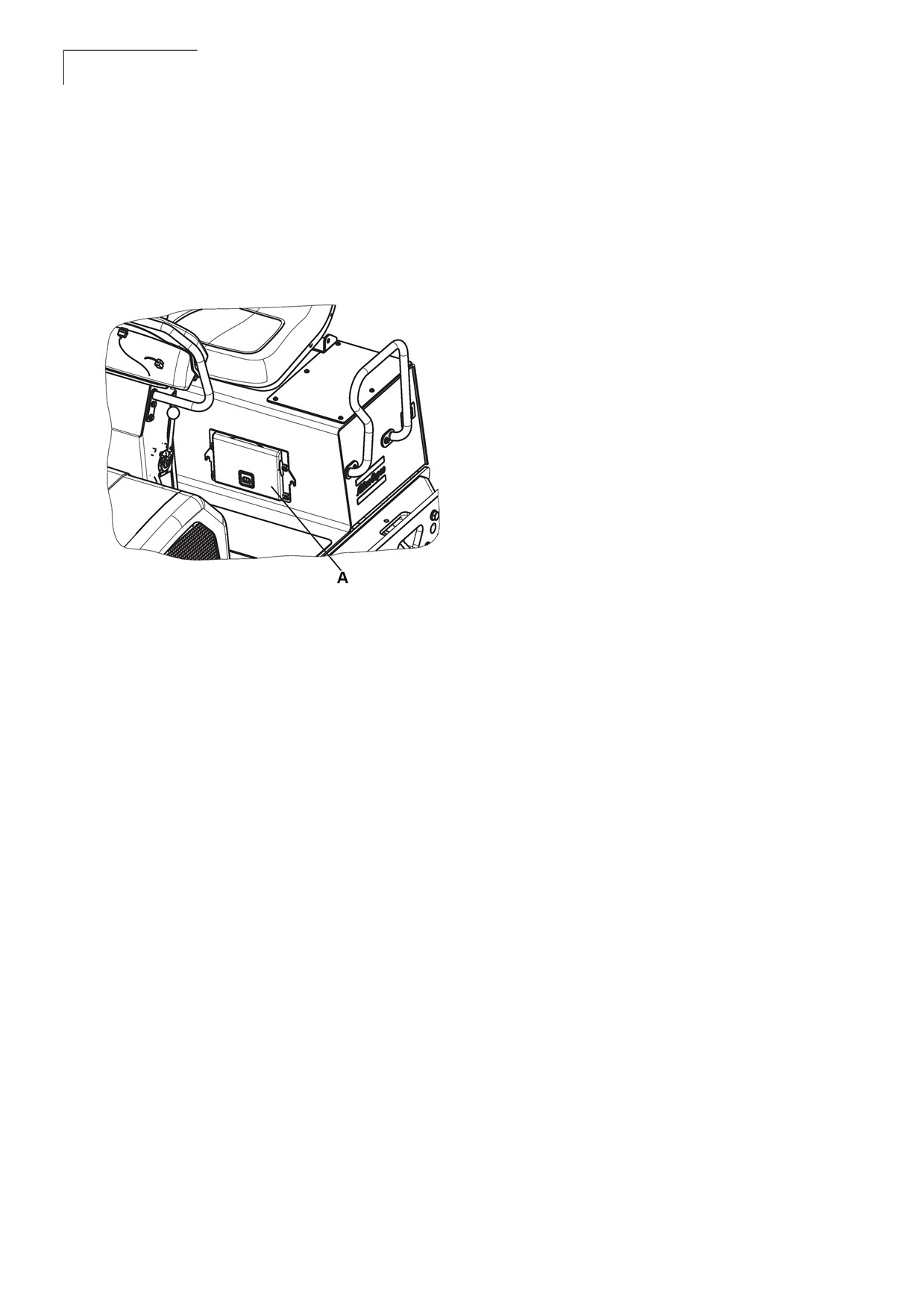
The instruction manuals are located under
An exact description of the model type and the
operator seat within easy access.
serial number of the roller facilitates fast and
efficient response from our parts and service
support operations.
Figure 1-1: Instruction manual Location
Provide the model type and serial number while
contacting the local Atlas Copco service or parts
office.
Enter your roller data on the following lines to
maintain roller and engine information necessary
to facilitate fast and efficient response from our
parts and service support operations:
Model:______________________________
Roller Serial
Number:_____________________________
Chassis VIN
Number:_____________________________
A Manual location
Year of
Manufacture:_________________________
Receiving the Roller
Engine (Mfg. and Type of
Engine):_____________________________
The CC 125 roller has been tested, accurately
checked, and prepared for shipment. Every part of
Engine Serial
the roller is accurately checked before being
Number:_____________________________
shipped from the factory.
When receiving the CC 125 roller and before
unpacking the equipment, check if damage has
occurred during transport and if any parts are
missing.
Check the equipment by consulting the shipment
documents.
If the goods are damaged or if parts are missing,
inform the freight agent and raise a complaint
against it.
CC 125
Introduction
3
Instruction Manual
Roller Identification
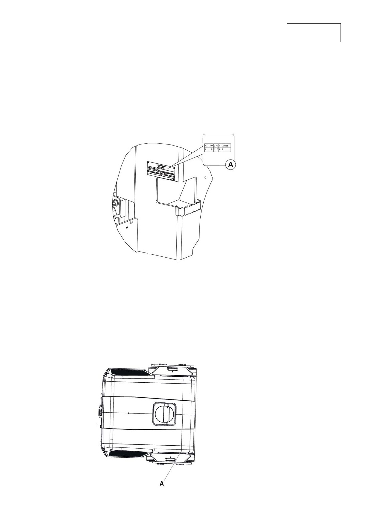
The machine Product Identification Number (PIN) plate is located on left hand side of the rear frame.
The PIN number is a 17 digit number which provides information about manufacturer, family model,
check letter, no coding, production unit, and serial number.
Figure 1-2: Location PIN
A Manufacturer
B Family/Model
A Serial number
C Check lett
D No coding
E Production unit
F Serial number
Pin number is punched on top right side of front frame.
Figure 1-3: Location PIN
A Pin number
CC 125
4
Introduction
Instruction Manual
Engine Identification
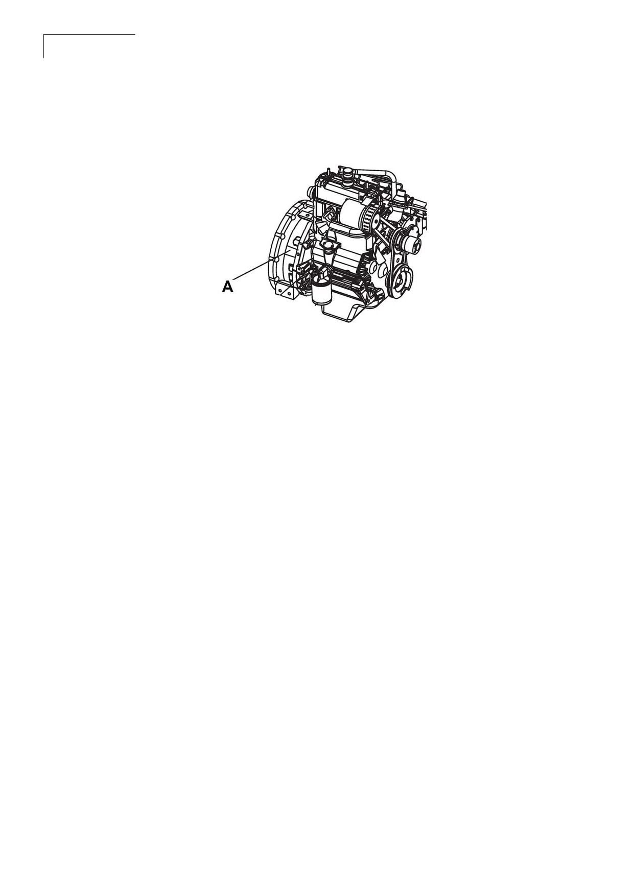
Figure 1-4: Identification Plate
A
Engine identification plate
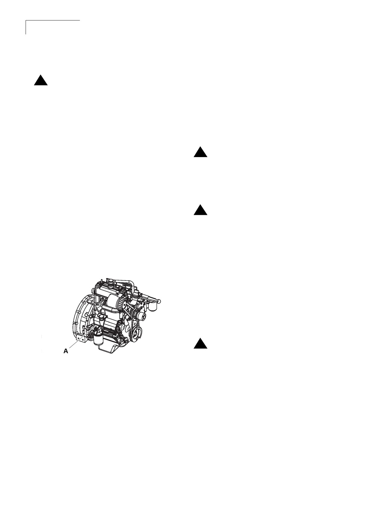
The engine identification plate located on flywheel housing near engine oil filter. The engine
identification plate provides model identification and other important data about the engine. Refer to the
engine operation and maintenance manual for further information on the identification information.
Have the following engine data available when communicating with an authorized repair location or
engine dealer. The data on the engine identification plate is mandatory when sourcing service parts:
•
Engine serial number
•
Model
CC 125
Introduction
5
Instruction Manual
1.2 Roller Description
CC 125 are two self-propelled vibratory tandem rollers in the three metric tonnes class featuring
1200 mm wide drums. The machines are equipped with drive, brakes, and vibration on both drums.
To permit optimum performance on a wide range of applications and site requirements, the roller is
equipped with:
Diesel engine
Electrical system
Propulsion system/transmission
Brake system
Secondary/parking brake
Steering system
FOPS and ROPS
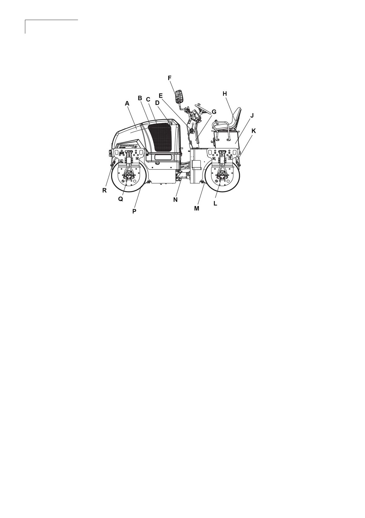
Identification of Major Components
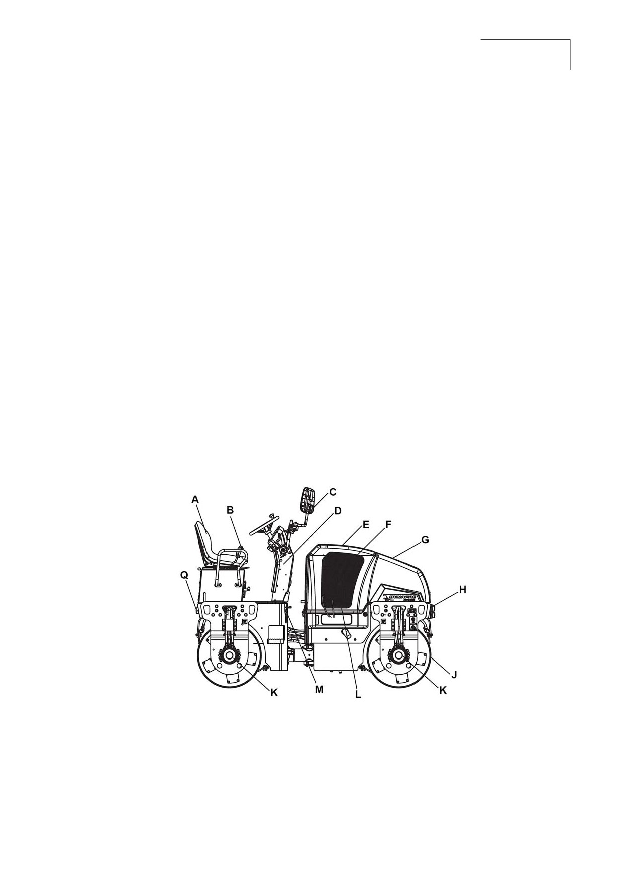
Figure 1-5: Major Components Right Side
A Seat
E Hood
J
Drum
B Forward and reverse lever
F
Engine
K Propulsion pump
C Mirror
G Water tank
L
Propulsion pump
D Steering console
H Lights
M Fuel tank
CC 125
6
Introduction
Instruction Manual
Figure 1-6: Major Components Left Side
A Hood
G Steering console
N Steering joint
B Engine
H Seat
P Drum
C Cooler
J
Platform
Q Vibration motor
D Air Cleaner
K Sprinkler system
R Scrapper
E Throttle lever
L
Vibration motor
F
Mirror
M Scrapper
Diesel Engine
The machine is equipped with a water-cooled, straight three cylinder, and four-stroke diesel engine.
CC 125
Introduction
7
Instruction Manual
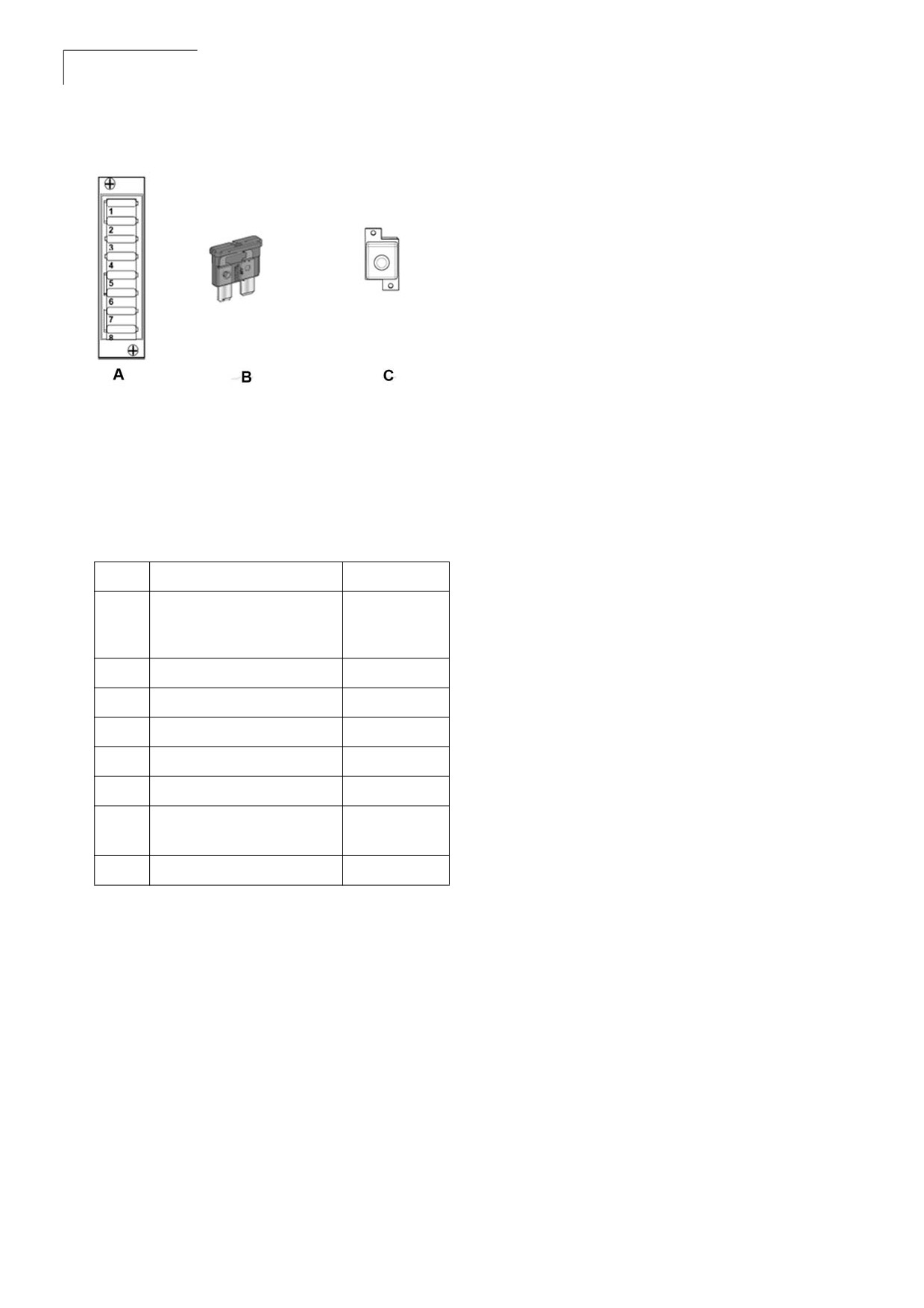
Figure 1-8: Fuses
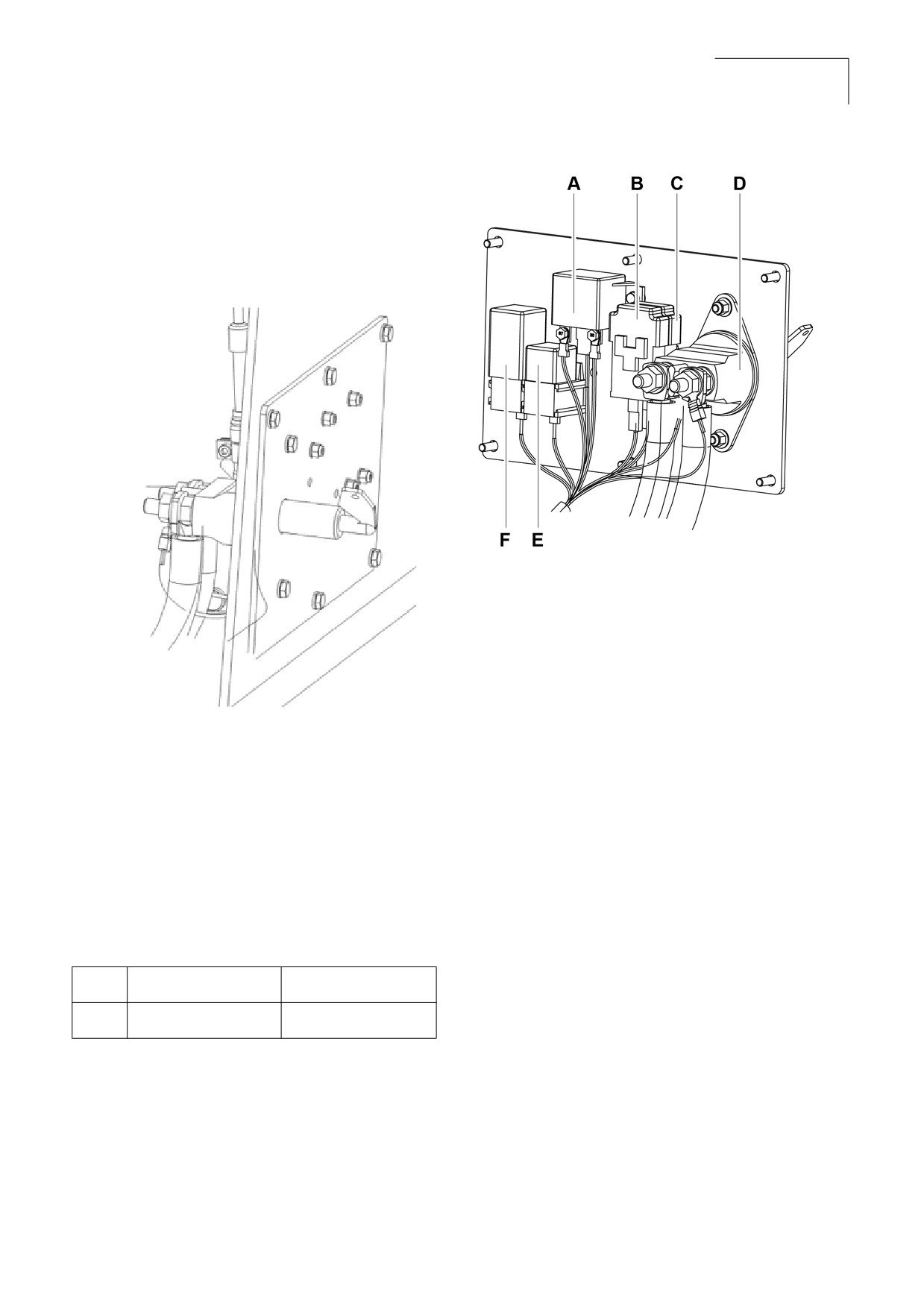
Electrical System
The roller is equipped with 12-V electrical system
and 36-A AC alternator.
Figure 1-7: Electric System
A
100-A Power relay
E
30-A Mini relay for
starter
B and C
30-A Main fuses
F Timer relay
D
Battery disconnector
switch
Main and Light Fuses
Fuse Boxes in Switch Box
The main fuse and light fuse are placed near to
The flat pin, type C (medium) fuses and first
the battery disconnector switch.
cavity 20-A fuse are used for driving lights.
On the same bracket, timer relay and 100-A
power relay for stop solenoid are placed.
Table 1: Placement of Fuses
F3
Main fuse
30 A
F4
Fuse-starter relay
30 A
CC 125
8
Introduction
Instruction Manual
Figure 1-9: Fuses- BoX
Brake system
The brake system consists of a service brake,
secondary brake and parking brake. The service
brake is hydrostatic and is activated by moving the
control lever to neutral.
Secondary/Parking Brake
The secondary and parking brake system
consists of spring multiple disc brakes in the
motors. The brakes are released with hydraulic
pressure and are operated with a switch on the
instrument panel.
A Fuse box
C Fuse for driving lights
B Fuse
Steering System
Table 2: Fuse Function and Amperage
The steering system is a hydrostatic system.The
control valve on the steering column distributes
Sl.No
Function
Amperage
the flow to the control cylinder, which actuates the
articulation.
1
Main fuse
20 A
(Ignition/Emergency/
The steering angle is proportional to the deflection
ECU/Vibration)
of the steering wheel.
2
Horn/Sprinkler Fuse
10 A
3
Empty
FOPS and ROPS
4
Flash input fuse
10 A
FOPS is the abbreviation for Falling Object
5
Rotating Beacon fuse
10 A
Protective Structure (roof protection) and ROPS is
6
Hazard
10 A
the abbreviation for Roll Over Protective
Structure. If any part of the FOPS/ROPS
7
Working Light switch
10 A
structure'sprotective construction displays plastic
illumination Fuse
deformation or cracks, the FOPS/ROPS structure
8
Working Light Load
10 A
mustbe replaced immediately. Never perform
unauthorized modifications on the FOPS/
ROPSstructure.
Propulsion System/
Transmission
The propulsion system is a hydrostatic system
with a hydraulic pump supplying two motors
connected in parallel. The motors drive the front
and rear drums.
The speed of the machine is proportional to the
deflection/angle of the control lever from neutral.
CC 125
Introduction
9
Instruction Manual
Roller Applications
The CC 125 roller is built in accordance with
international standards and recognized safety
rules. Nevertheless, misuse may constitute a risk
to the life and limb of the user or third parties, and
may cause damage to the roller or other material
property.
The CC 125 roller must be used in accordance
with its designated use as described in this
manual. The roller must only be operated by
trained, safety-conscious persons who are fully
aware of risks involved in operating the roller. Any
functional disorders, especially those affecting the
safety of the roller, must be corrected
immediately.
Designated Applications
The CC 125 roller is designed primarily for
compaction of asphalt. It has excellent
compaction capacity for reinforcement layers and
bearing courses.The roller is mainly intended for
compacting asphalt on streets and minor roads in
towns. It has sufficient capacity to follow a small
asphalt paver.
Non-Designated Applications
The CC 125 roller is not designed to use as a
ladder, support, or a work surface. it is not used to
carry or transport passengers or equipment. The
manufacturer/supplier cannot be held liable for
any damage resulting from such use. The risk of
such use lies entirely with the user.
Operating the CC 125 roller within the limits of its
designated use also involves compliance with the
inspection and maintenance directives contained
in the operating manual.
This page is intentionaly left blank
CC 125
Safety First
11
Instruction Manual
Section 2:Safety First
2.1 General Information
This information is intended as a guide for trained and qualified personnel who are aware of the dangers
involved in handling potentially hazardous equipment. It is not intended to contain a complete list of all
safety precautions which should be observed by personnel using this equipment.
Before you operate, maintain, work around, or in any other way use this equipment:
Note Read and study the Safety Manual, and this Instruction Manual.
Note Ensure that all instructions in the maintenance section are followed. Failure to obey
instructions or warnings could result in injury or death.
•
Those who operate, maintain, and work on equipment must be competent.
•
The maintenance and service of this equipment involves risks both to personnel and equipment
and must be performed only by qualified personnel exercising caution.
•
Personnel engaged in the operation, maintenance, or servicing of this equipment are urged to
become familiar with First Aid theory and practices.
•
During operation of this equipment, local safety, and fire protection standards must be observed.
•
Do not use the roller in need of adjustment or repair. Mount and dismount the roller when it is
stationary. Use the intended grips and rails. Always use the three-point grip (both feet and one
hand, or one foot and both hands) when mounting or dismounting the machine. Do not jump on or
off a moving machine.
•
It strictly advised to use the ROPS (Roll Over Protective Structure), when the machine is operated
on unsafe ground.
•
Drive slowly and carefully during the sharp bends or during the uneven ground.
•
Avoid driving across slopes. Drive straight up or straight down the slope.
•
The seat belt must be fastened while driving.
•
Replace all the lost and damaged safety labels.
•
Keep the roller in good working condition.
•
Safety measures during refueling:
• Make sure to stop the engine.
• Do not smoke.
• Do not use naked flames in the vicinity.
• Ground the nozzle of the filling device against the tank to prevent sparks.
This safety summary includes general safety precautions and instructions that must be understood and
applied during operation and maintenance to make sure personnel safety and protection of equipment.
Before performing any task, the WARNINGs, CAUTIONs, and NOTEs included in that task shall be
reviewed and understood.
CC 125
12
Safety First
Instruction Manual
Warnings and Cautions
Personnel Protective
Equipment
Throughout the manual, Warnings, Cautions, and
Notes symbols are used to designate instructions
Anyone working around the roller must wear
of particular importance. Look for these symbols
approved safety equipment (safety shoes or
which point out items of extreme importance to
protective footwear, safety glasses, hearing
you and your co-workers’ safety. Read and
protection, hard hat, gloves, respirator, and the
understand thoroughly. Heed the warning and
like) when operating or maintaining the machine.
follow the associated instructions. In this manual,
Wear close fitting clothing and confine long hair.
these terms have the following significance:
Operating requires full attention of the operator.
Do not wear radio or music headphones while
operating.
WARNING ! Marks a danger or a
!
hazardous procedure that can result in
life threatening or serious injury if the
Tools and Equipment
warning is ignored.
Tools, lifting gear, fastening devices,
!
jacks, and other working equipment must
CAUTION ! Marks a danger or hazardous
be in safe operational working
!
procedure that can result in damage to
conditions.
the machine or property if the warning is
ignored.
Equipment or components which are
!
being fitted or removed or where their
Note Note is used for supplementary
installation position is being changed,
information not directly effecting
must be secured against unintentional
safety or damage to equipment. Note
movement, slipping, or falling over. Use
can also refer to special information
suitable lifting gear or suspension/
on the efficient use of the roller.
support devices.
Systems and units (tensioning units)
Modifications
!
must be depressurized in an appropriate
manner before opening.
The equipment is designed for safe operation. Do
not do anything that may hamper the safety
features or structural integrity of the equipment
Damaged hydraulic or mechanical pre-
!
tensioned spring elements must be
Do not make any unauthorized modifications to
exchanged as a completed unit. Further
this equipment. Atlas Copco cannot be held
information can be found in the
responsible for any accidents, incidents, or
respective component descriptions and/
damage to persons or property that are related to
or fitting and removal instructions.
the use of modified equipment.
CC 125
Safety First
13
Instruction Manual
Operating Safety
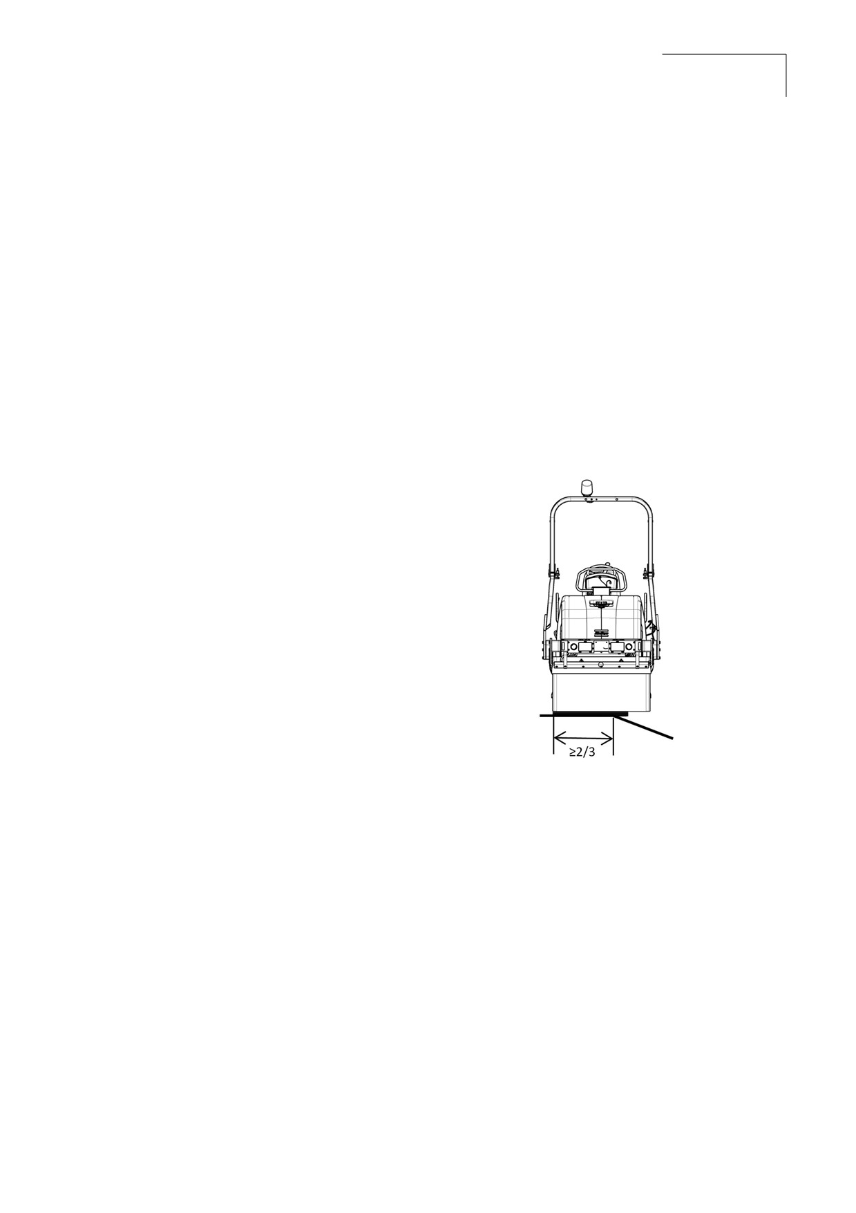
Driving Near Edges
Know the working area. Familiarize with work site
While driving near an edge make sure to maintain
obstructions and any other potential hazards in
2/3 of the drum width on the solid ground.
the area.
Note
The machine's center of gravity moves
outwards when steering. For example,
Before Starting the Engine
the center of gravity moves to the right
•
Inspect the roller for potential hazards.
when you steer to the left.
•
Adjust the rear view mirrors for good visibility.
Note
Never operate machine on side
slopes. The machine may roll over,
•
Make sure that the controls are in the neutral
even on stable ground. Always
position and the parking brake is applied.
operate the machine parallel to the
•
Make sure that there is no one in the immedi-
slope; never perpendicular.
ate vicinity and there are no obstructions
around the machine.
Figure 2-1:Position of the Drum
Starting the Equipment
•
Do not start the engine or move any of the
controls if there is a warning tag attached to
the controls. Check with the person who
attached the tag before starting.
•
Read and follow all the instruction decals.
•
Before starting the engine, check that all the
gear controls are in neutral position.
•
Always inspect the motor before and after
starting.
•
Check all the safety devices. Report any
defects immediately.
•
Listen for unusual noises.
•
Engage hydraulic controls slowly in cold
weather to avoid shock loading.
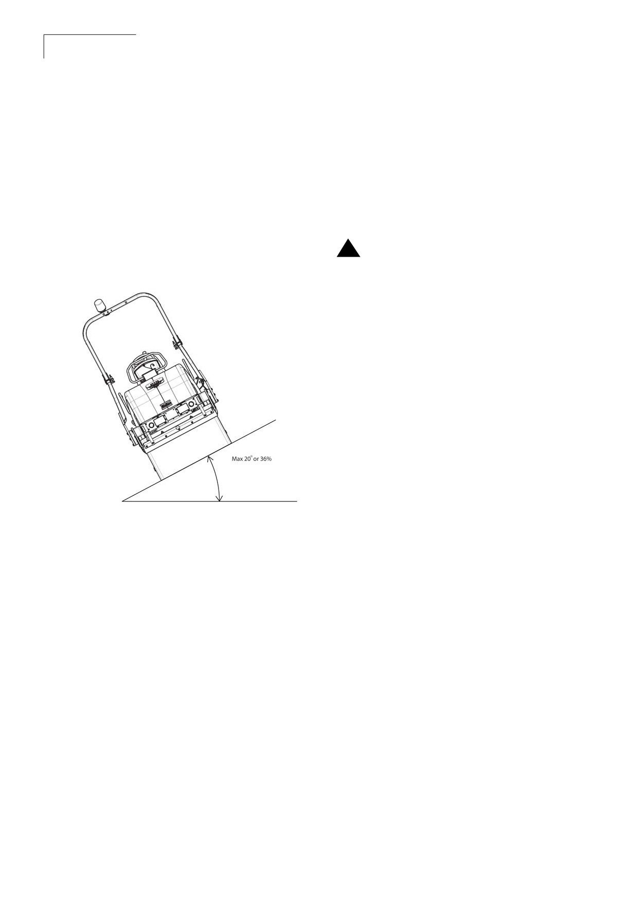
Slopes
Parking the Roller
The slope angle is measured on a hard, flat
surface with the machine stationary. The steering
•
Select the level and hard ground. If necessary
angle was zero, the vibration was switched OFF
to park on the slope, block the front of the
and all tanks were full.
drums on the downside of the slope.
•
Apply break in an emergency conditions.
CC 125
14
Safety First
Instruction Manual
Always take into consideration that loose ground,
Hydraulic Maintenance
steering the machine, vibration on, machine
Safety
speed across the ground and raising the center of
gravity can cause the machine to topple at smaller
The normal operating temperature of hydraulic oil
slope angles than those specified here.
is hot enough to cause serious burns. Use
precautions when working on any hot fluid lines or
Note It is recommended that ROPS (Roll
changing filters.
Over Protective Structure) or a ROPS
approved cab, is always used when
driving on slopes or unsafe ground.
Hot oil or components can burn. Avoid
!
contact with hot oil or components. Do
not allow used oil to drain into the
Figure 2-2:Operating on the Slopes
ground. Dispose the used oil properly in
accordance with the local guidelines.
Cylinder Repairs or Replacement
•
When repairing cylinders, make sure to block
them up to prevent dropping or rolling off the
equipment.
Handling Fluids and Oil
•
When draining fluids, make sure that
adequate sealable containers are available
and that every care is taken to prevent
spillage.
•
Always make sure waste fluids are disposed
in an environmentally safe manner.
•
Always make sure that used filters are stored
Gas Spring
in secure containers and disposed of in an
environmentally safe manner.
•
Do not expose gas spring to excessive heat
or naked flames.
•
Under any circumstances, gas springs must
not be exposed to damaging external influen-
ces or violent handling.
•
Do not try to use a gas spring that exhibits
tiny dents or bends on its cylinder.
CC 125
Safety First
15
Instruction Manual
Transporting
•
Use only appropriate means of transport and lifting gear of adequate capacity.
•
Fastening of loads and instructing the crane operators should be entrusted to the
experienced persons only. The person giving the instructions must be within sight or sound of the
operator.
•
Do not attempt to load the equipment on the transport vehicle without knowledge and experience
with the operation of the
equipment.
•
Use proper chock blocks in front and rear of the wheels of the transport vehicle when
loading the equipment.
•
Position the equipment on the transport vehicle centered from side to side and use proper chock
blocks in front and rear of the tracks.
•
Secure the equipment to the deck of the transport vehicle with adequate chains or cables and
blocks to meet local regulations.
•
When moving the equipment on public access roads, obey all traffic regulations and make sure
that proper clearance flags, lights, and warning signs are properly displayed. Never turn corners at
excessive speeds. Look in all directions before reversing the travel direction.
CC 125
16
Safety First
Instruction Manual
2.2 Equipment Safety Decals
Before you operate, maintain, work around, or in any other way use this roller, read and understand the
safety decals and safety labels located on the roller. Follow all directions on the labels. Do not remove
or deface the labels. Replace them if they become damaged or lost
Table 1: Decal List
Decal
Message
Location
Warning - Crush zone
Quantity 2: Located on side of
the hydraulic reservoir.
Warning - Rotating engine
Quantity1: Located on rear left
components
side of the hood.
Quantity1: Located on rear right
side of the hood.
Warning: Hot surfaces
Quantity 2: Located on cooler
housing.
Warning: Instruction manual
Quantity 2: Located on top of
receiver and on receiver end
plate.
Warning - Risk of crushing
Quantity2: Located on the front
left and right side fork.
Warning: Combustible Gas
Quantity 1: Located on the
carrier battery box.
CC125
Special Instructions
17
Instruction Manual
Section 3:Special Instructions
3.1 Operational Limitations
Standard Lubricants and Other Recommended Oils and
Fluids
Before leaving the factory, the systems and components are filled with the oils and fluids specified in
the lubricant specification. These are suitable for ambient temperatures in the range 5°C to +45°C
(41°F to 113°F).
Higher Ambient Temperatures
For operation of the machine at higher ambient temperatures, however maximum +50°C (122°F).
The diesel engine can be run at this temperature using normal oil.
Hydraulic system - mineral oil Shell Tellus S2V68 or similar.
Lower Ambient Temperature - Freeze Risk
Make sure that the watering system is empty/drained of water (sprinkler, hoses, tank/s) or that
anti-freeze has been added, to prevent the system freezing.
Temperatures
The temperature limits apply to standard versions of rollers.
CC125
18
Special Instructions
Instruction Manual
Note Specifications represented are
High Pressure Cleaning
calculated values at 100% efficiency.
Do not spray water directly onto electrical
components or the instrument panels.
Operator life may be endangered if the
!
following is not complied with. Do not add
attachments to the roller that intrude into
Place a plastic bag over the fuel filler cap and
the operator protective area, reduce
secure with a rubber band. This is to avoid high
visibility, restrict emergency exits, or add
pressure water entering the vent hole in the filler
weight exceeding certification weight.
See the operation manual or contact the
cap. This could cause malfunctions, such as the
dealer for complete inspection
blocking of filters.
requirements and maintenance
instructions.
Do not spray with high-pressure cleaner directly
onto gaskets and bearing spacings in steering
Grade Limitations
hitch.
Exceeding the slope or grade limitations of the
roller and its configuration can cause the roller to
Do not spray water directly onto electrical
tip over. Prior to moving the roller into position,
!
components or the instrument panels.
always determine the safe operating grade of the
Place a plastic bag over the fuel filler cap
roller.
and secure with a rubber band. This is to
avoid high pressure water entering the
vent hole in the filler cap. This could
Fire Fighting
cause malfunctions, such as the blocking
of filters.
If the machine catches fire, use an ABC-class
powder fire extinguisher.
Ambient Temperature
A BE-class carbon dioxide fire extinguisher can
Range
also be used.
The ambient temperature working range between
limits of 5°C and 45°C (41°F and 113°F).
Operating Conditions For
Stability
Stability is affected by the orientation of the roller,
surface stability (bearing strength), and wind
conditions.
Travel at a safe speed relevant to
!
surrounding conditions.
Contact the local Atlas Copco distributor, dealer,
or service office for further information.
CC125
Special Instructions
19
Instruction Manual
Roll Over Protective
Jump Starting
Structure (ROPS)
Do not connect the negative cable to the
!
negative terminal on the dead battery. A
Operator life may be endangered if the
spark can ignite the oxy-hydrogen gas
!
following is not complied with. Do not add
formed around the battery.
attachments to the roller that intrude into
the operator protective area, reduce
visibility, restrict emergency exits, or add
Check that the battery used for jump
weight exceeding certification weight.
!
starting has the same voltage as the
See the operation manual or contact the
dead battery.
dealer for complete inspection
requirements and maintenance
instructions.
Turn the ignition and all power consuming
equipment off. Switch off the engine on the
Never attempt to repair a damaged ROPS
machine which is providing jump start power.
!
structure or cab. These must be replaced
with new ROPS structure or cabs.
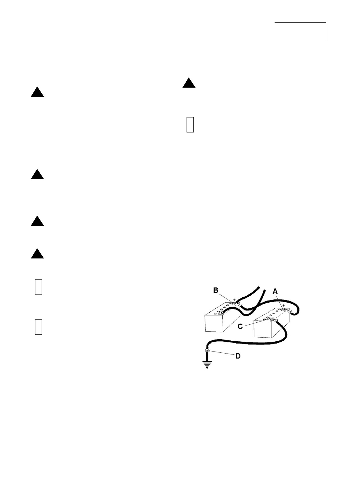
First connect the jump start battery's positive
terminal (1) to the flat battery's positive terminal
Battery Handling
(2).Then connect the jump start battery's negative
terminal (3) to, for example, a bolt (4) or the lifting
When removing batteries, always
eye on the machine with the flat battery.
!
disconnect the negative cable first.
Start the engine on the power providing machine.
Let it run for a while. Now try to start the other
When fitting batteries, always connect the
machine. Disconnect the cables in the reverse
!
positive cable first.
order.
Dispose of old batteries in an
Figure 3-1:sJump Starting
!
environmentally friendly way. Batteries
contain toxic lead.
Do not use a quick-charger for charging
!
the battery. This may shorten battery life.
A
Battery's positive terminal one
B
Battery's positive terminal two
C Battery's negative terminal three
D Battery's negative terminal four
This page is intentionaly left blank
CC 125
Specifications
21
Instruction Manual
Section 4: Specifications
4.1 Weight and Dimensions
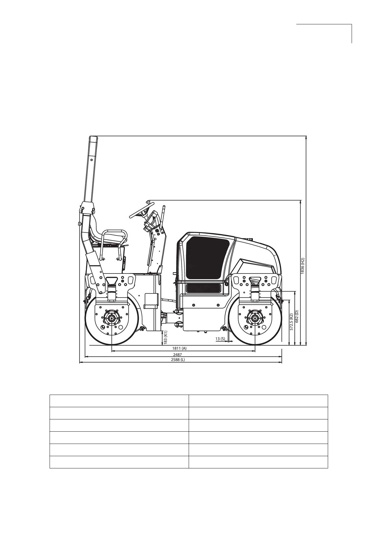
Figure 4-1:Dimensions, Side View
Table 1: Weight and Dimensions Side View
Wheel base
1811 mm (71.3 in)
Length
2588 mm (101.89 in)
Height, with ROPS
2649 mm (104.3 in)
Height, without ROPS
1836 mm (72.3 in)
Thickness
13 mm (0.5 in)
Weight Standard equipped roller
3100 kg (6834.3 lbs)
CC 125
22
Specifications
Instruction Manual
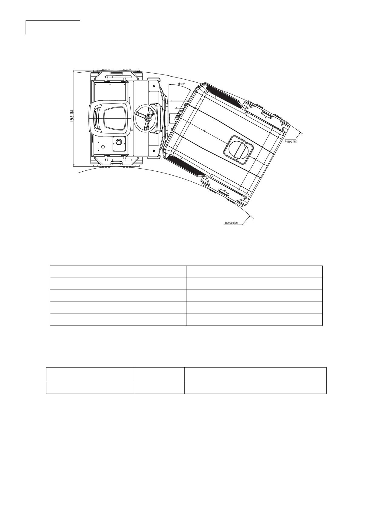
Figure 4-2:Dimensions Top View
Table 2: Weight and Dimensions Top View
Machine width with ROPS
1447 mm (57 in)
Machine width without ROPS
1262 mm (49.7 in)
Turning radius outer
4100 mm (149.6 in)
Turning radius inner
2900 mm (114.2 in)
Drum width
1200 mm (47.2 in)
Diesel Engine
Table 3: Diesel Engine
Engine
Model
HP (kW) rpm
Mahindra
MDI 1895
38.5HP (28.6kW) - 2600rpm
CC 125
Specifications
23
Instruction Manual
Fluid Volume
Table 4: Fluid Volumes
Fuel tank
50 L (13.2 gal)
Water tank
160 L (42.2 gal)
Hydraulic tank
45 L (11.9 gal)
Drum oil
5 L (1.3 gal)
Coolant
12 L ( 3.17 gal) Coolant + 8 L (2.1gal) Water
Working Capacity
Table 5: Working Capacity
Static linear load front
12.5 kg/cm
Static linear load rear
13.3 kg/cm
Amplitude
0.5 mm (0.01 in)
Vibration frequency
58 Hz
Centrifugal force
27 kN
Hydraulic System
Table 6: Hydraulic System
Opening pressure (Absolute pressure)
MPa
Drive system
35.0
Vibration system
21.0
Steering system
17.5
Charge pressure
2.0
Brake release
2.0
This page is intentionaly left blank
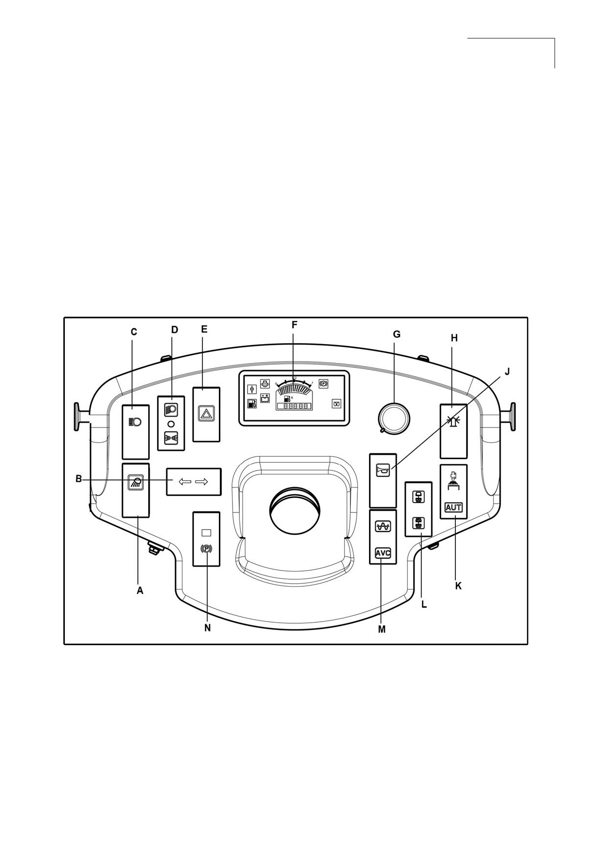
CC 125
Operation Controls
25
Instruction Manual
Section 5: Operation Controls
5.1 Instruments and Controls
The instruments and controls section of this manual provides basic information about the operating
controls, instruments, and indicators located on the consoles and around the roller.
All the operation control from the operator console located in front of operator seat under steering
wheel. The slim profile and quick opening side panels provide easy access for maintenance and
service.
Figure 5-1: CC 125 Console
A
Working light
H Rotating beacon
B
Direction indicators
J
Horn
C High beam
K Manual/automatic sprinkler
D Driving lights
L
Vibration selector front/rear drum
E
Hazard warning lights
M Vibration manual/automatic
F
Control panel
N Parking brake On/Off
G Sprinkler timer
CC 125
26
Operation Controls
Instruction Manual
Starter Switch
Throttle Lever
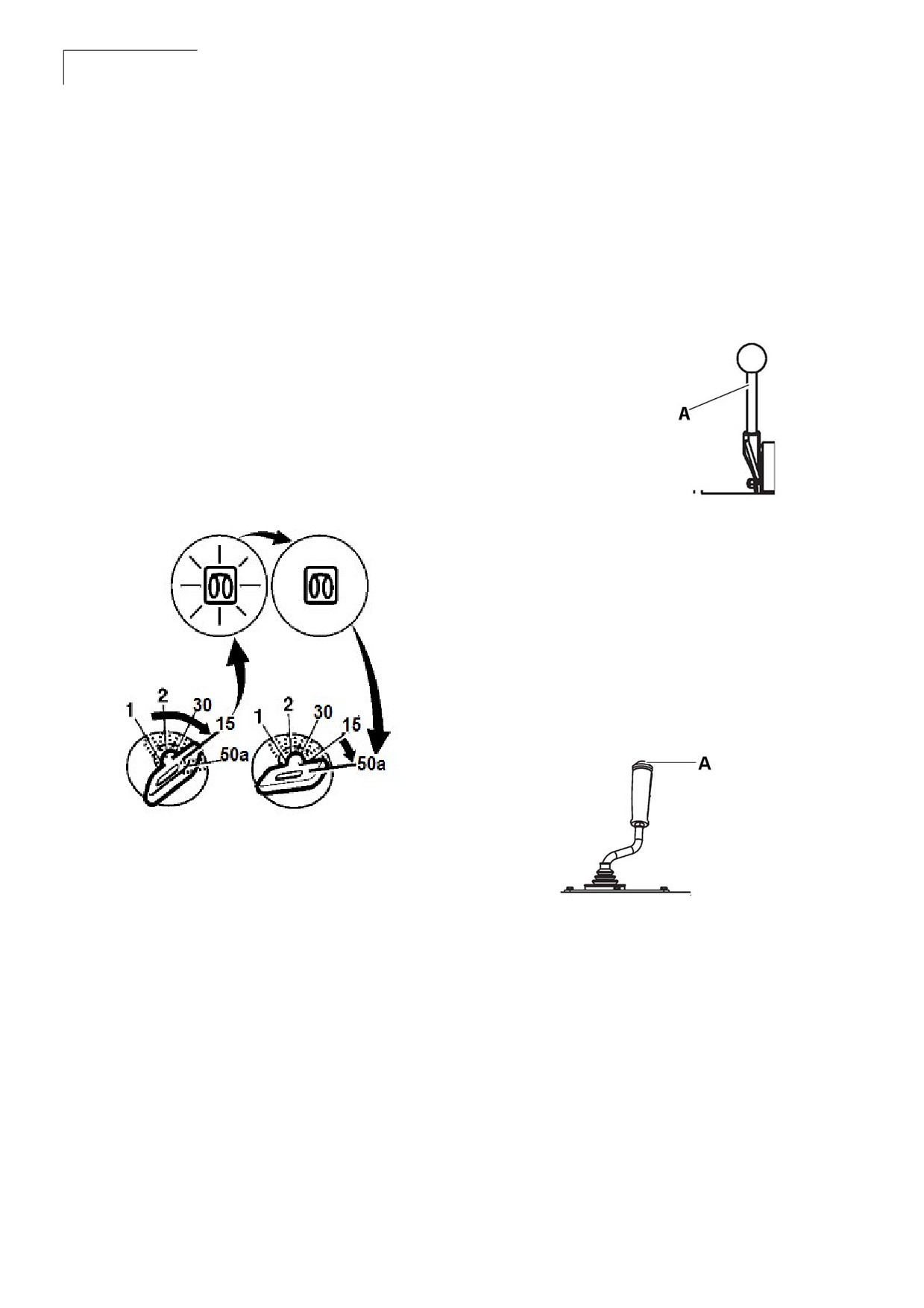
The starter switch starts and stops the engine.
The throttle control regulates the speed of the
There are three positions in the starter switch,
engine. In forward position, the engine idles and in
they are:
the backward position, the engine runs with a full
speed.
•
OFF position: In this position all the electric
systems and the engine are switched off, and
the key can be removed.
Figure 5-3:Throttle Control
•
ON position: In this position, Engine is on run
mode. Charging circuit and lamp circuit are
energized.
•
Start position: In this position, the engine
cranks. Make sure to allow the switch to on
position until the engine is started.
A Throttle lever
Figure 5-2:Starter Switch
Vibration On/Off Switch
Vibration On/Off switch is a push button used for
vibration. Press and release to switch on the
vibration and press again to switch it off.
Figure 5-4: Vibration On/Off Switch
1
Off position
30
Start position to supply power
to the instruments and controls
2
On position
15
Hold position
50 a Starter motor activation.
A Vibration On/Off switch
CC 125
Operation Controls
27
Instruction Manual
Emergency Stop
Sprinkler Switch
The emergency button is used to stop the engine
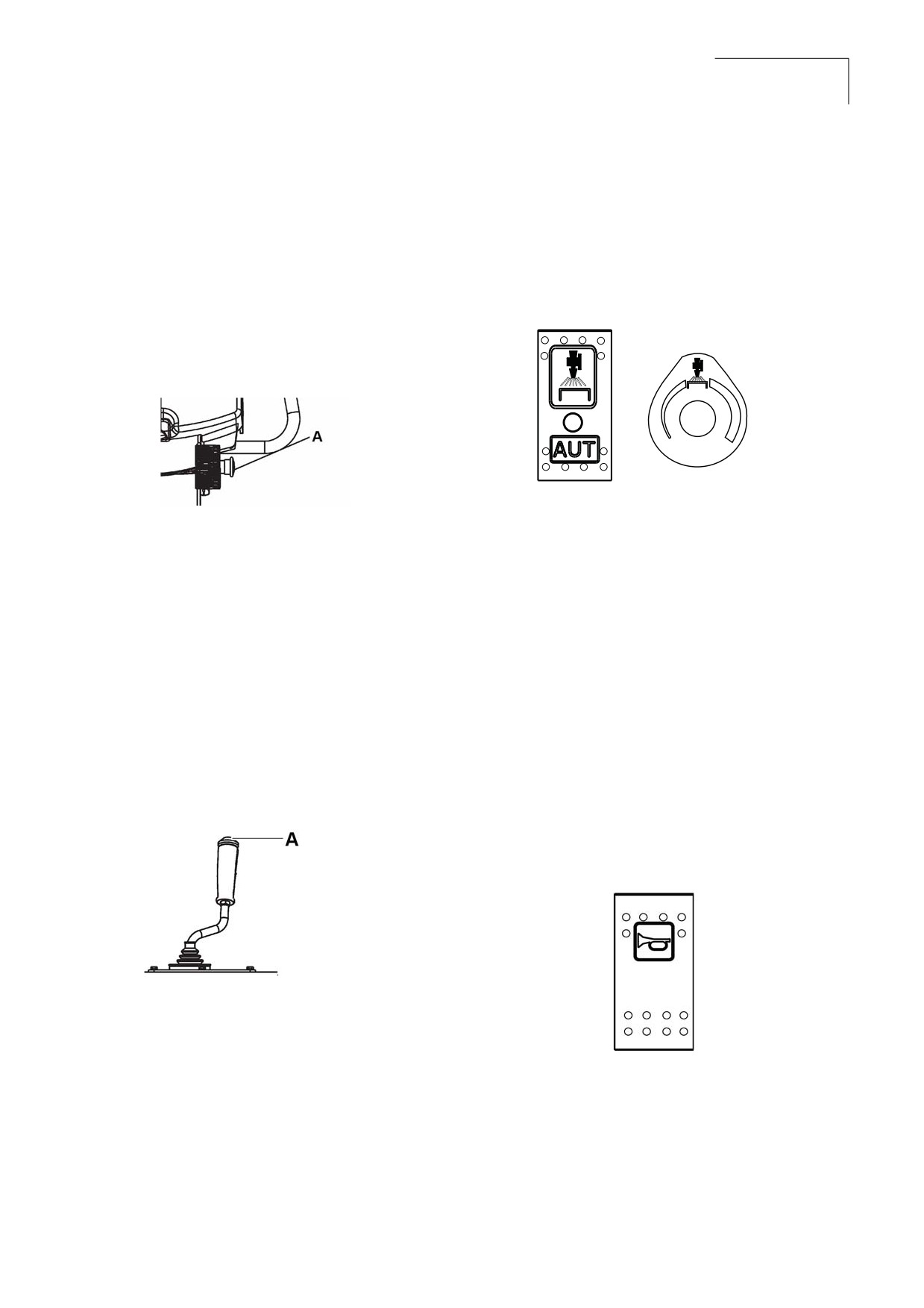
Sprinkler switch controls the flow of water to the
in an emergency situation which it cannot be shut
drum. Push up to flow the water and down to stop
off in an usual manner. It switches off the engine
the flow of water.
and activates the brakes. The emergency stop
aborts the entire control operation in a quicker
Figure 5-7: Sprinkler Switch
way for the safety of the personnel.
Figure 5-5: Emergency Stop
Seat Buzzer
A Emergency stop button
Seat buzzer beeps if the operator is not seated
during the operation of the roller and it continues
Forward/Neutral (FNR)
to beep until the operator is seated. If the buzzer
Lever
beeps for long the brakes are activated and
engine is forced to stop.
Direction of travel and speed of the roller is
regulated with the forward/reverse lever. The
machine speed increases or decreases in
Horn Button
proportion to the position of the lever.
The horn button is located on the switch
assembly.
Figure 5-6: FNR Lever
Press the button to activate the horn.
Figure 5-8: Horn Switch
A FNR lever
CC 125
28
Operation Controls
Instruction Manual
Vibration Man/Auto Switch
Driving Lights Switch
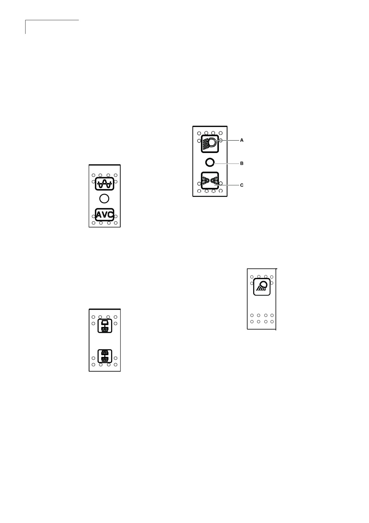
In the upper position, the vibration is switched on/
Push up, to switch on the driving lights and
off with the switch on the forward/reverse lever.
depress to switch on the parking lights. In
The function is activated with the switch. In the
Intermediate position the lights are switched off.
intermediate position the vibration system is
completely switched off. In the lower position the
Figure 5-11: Driving Lights
vibration is switched on or off automatically
through the forward/reverse lever.
A Push up position
B Intermediate position
Figure 5-9: Vibration MAN/AUTO Switch
C Depressed position
Working Lights
Switch(Optional)
Depress the switch to switch on the working lights.
Vibration Selector Switch
In the upper position the vibration is switched off
Figure 5-12: Working Lights
on the front drum and in the lower position the
vibration is switched on in both the drums.
Figure 5-10:Vibration Selector Switch
Fuse Box
The fuse box is located on the control column
which contains the fuses for the electrical system.
Fuses protect the electrical components from
damage because of a short circuit. Refer to
electrical system for the description and functions
of the fuses.
CC 125
Operation Controls
29
Instruction Manual
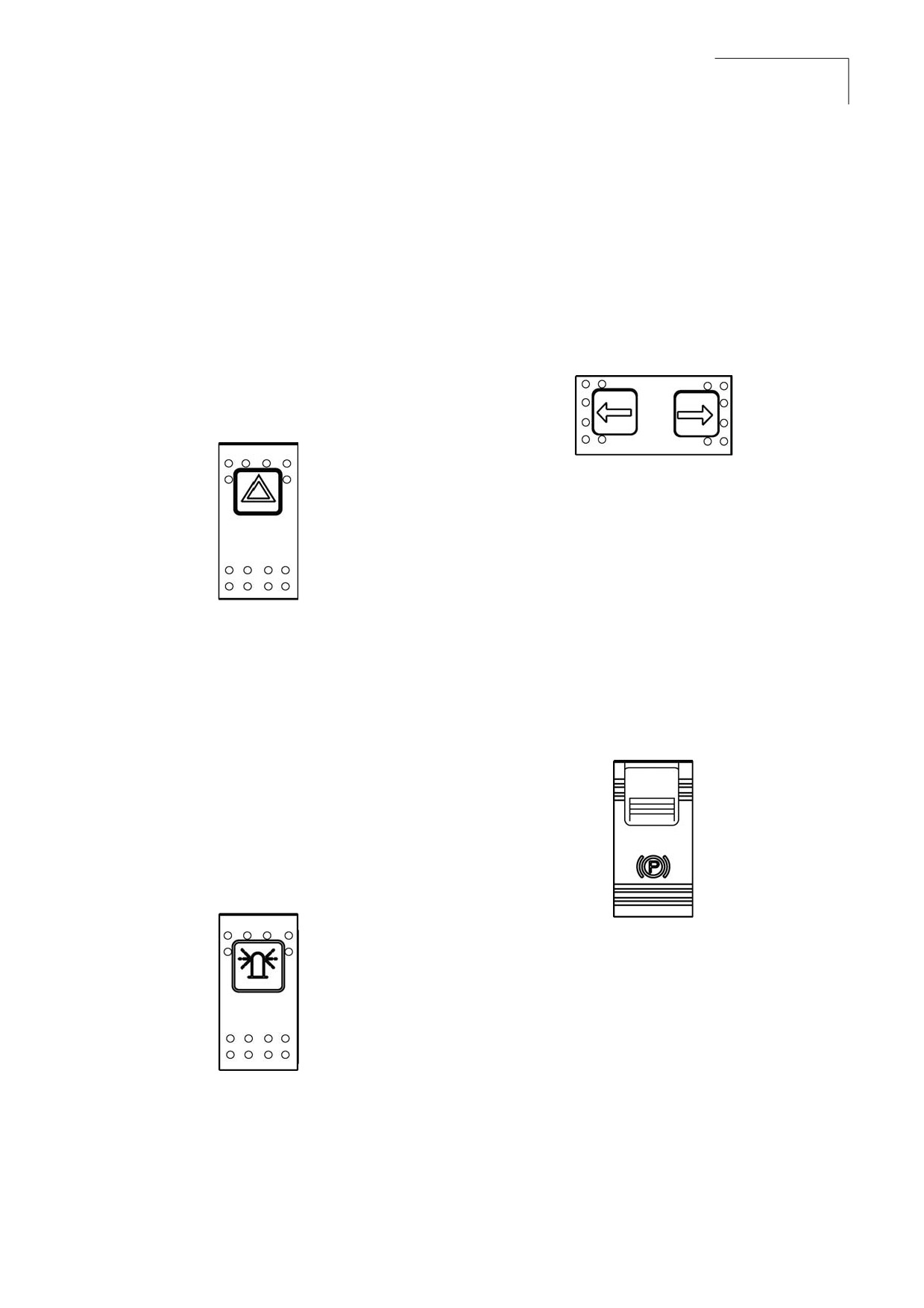
Hazard Warning Lights
Direction Indicator Switch
Switch
The direction indicators are blinking lamps
Hazard warning lights are primarily used to warn
mounted near the left and right, front and rear
other vehicles that there is a problem either with
corners of the roller. Depress the switch either left
the roller, or there is a hazard in front of roller
or right, to on the left or right indicators. In the
causing the operator to reduce speed quickly.
middle position the function is shut off.
Depress the switch to switch on the hazard
Figure 5-15: Directional Indicator Lights
warning lights.
Figure 5-13: Hazard Warning Lights
Parking Brake On/Off
Switch
The parking brake On/Off switch is used to
activate the parking brake.
Note Parking brake must be activated while
Rotating Beacon
starting the engine. Always activate
Switch(Optional)
the parking brake when the machine is
stationary on a sloping surface.
Rotating beacon lighting is generally used to warn
the approaching machine of potential hazards,
such as machine that is stopped or moving slower
Figure 5-16: Parking brake On/Off Switch
than the rate of the traffic.
Depress the switch to switch on the rotating
beacon.
Figure 5-14: Rotating Beacon Switch
CC 125
30
Operation Controls
Instruction Manual
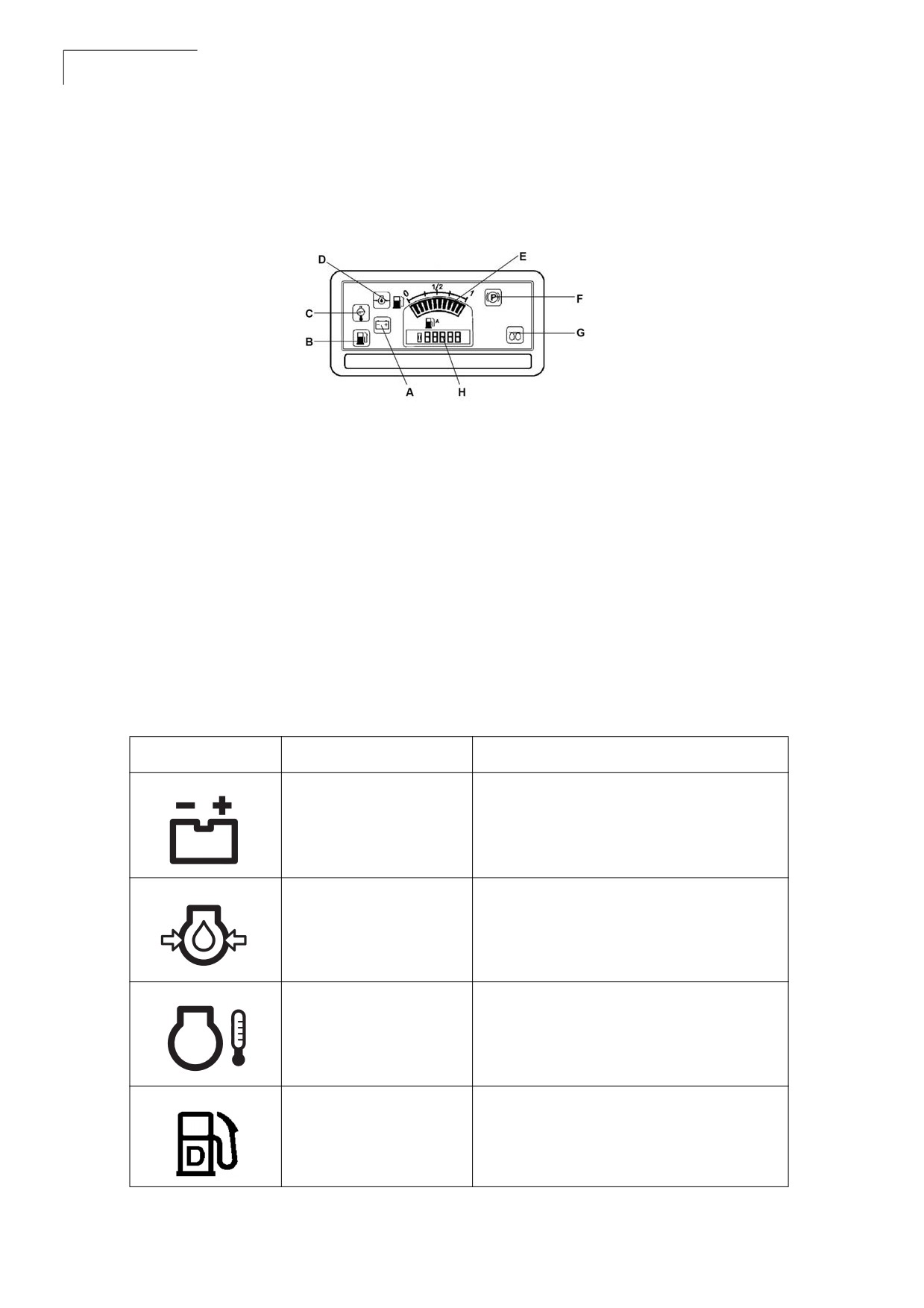
Control Panel
Figure 5-17: Control Panel
A
Battery/charging
E
Fuel level
B
Low fuel level
F
Parking brake lamp
C
Engine water temperature
G Glow plug
D
Oil pressure, engine
H Hourmeter
Control Panel Warnings Symbols
Warning lights comes on when the starter switch is turned to the on position and should goes off once
the engine has started. If the lights comes on when the engine is running indicates a faulty condition.
Table 1: Warning Lights
Designation
Function
Description
Battery charging
If light does not illuminate when ignition is
indicator lamp.
switched on, illuminates after engine is
started, the battery is not charging. Contact
maintenance personnel if the lamp comes
on during tramming.
Diesel engine lubricating
If the pressure is too low, the lamp comes
oil pressure indicator
on and the parking brake is applied. In this
lamp.
event, switch the engine off immediately
and rectify the cause. Contact maintenance
personnel.
Engine temperature
The lamp comes on when the temperature
signal lamp.
is too high. The engine must be switched
off immediately and contact the
maintenance personnel if the lamp comes
on during tramming.
Low fuel level indicator.
This lamp comes on if the oil level is low in
the fuel tank.
CC 125
Operation Controls
31
Instruction Manual
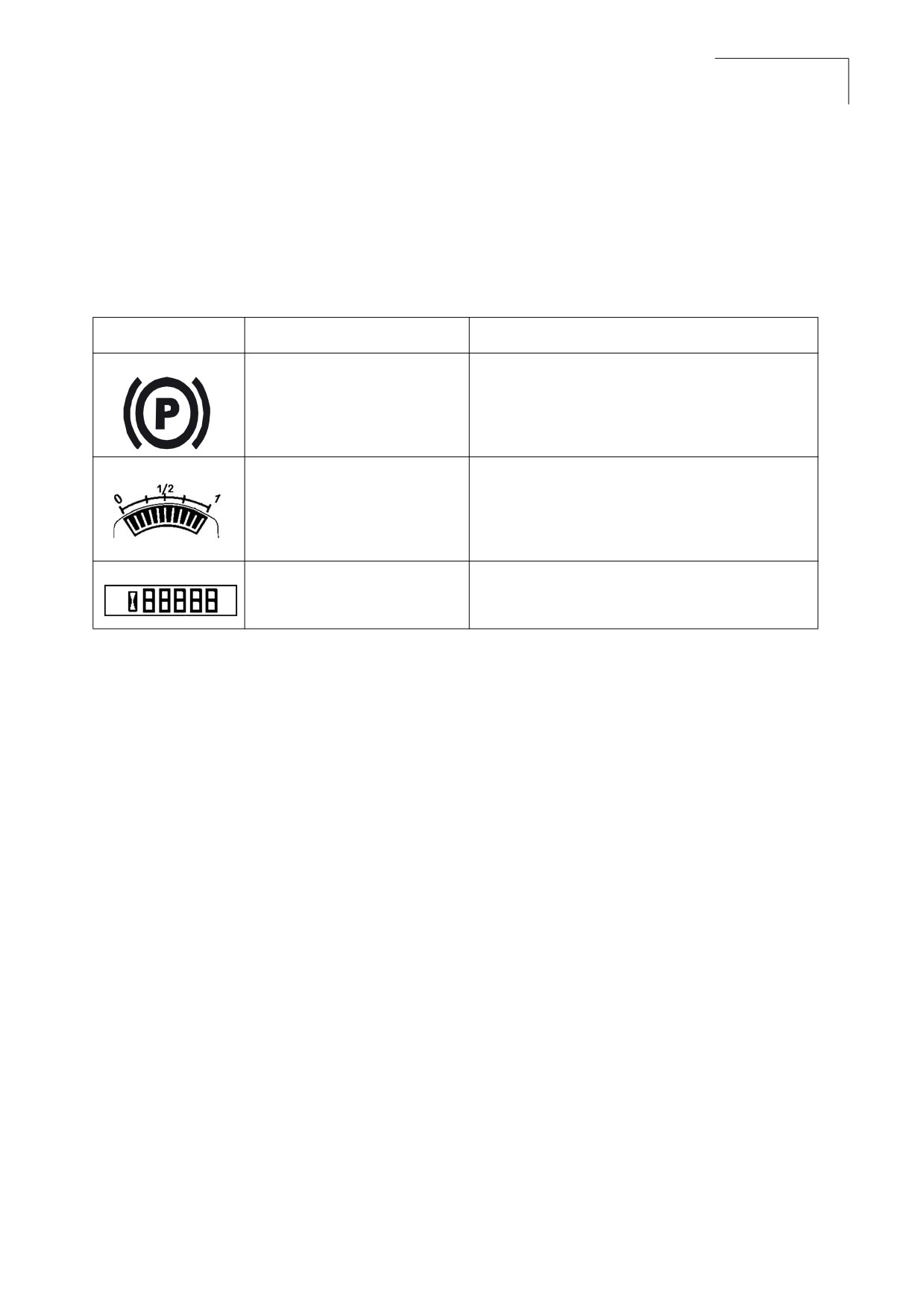
Control Panel Notification Symbols
Notifications are displayed when the starter switch is turned to the on position and notifies that
corresponding systems are operating.
Table 2: Notification Lights
Designation
Function
Description
Parking brake indicator lamp
The light illuminates when the parking brake is
activated.
The fuel level gauge
The fuel level gauge monitors the level of fuel in
the fuel tanks of the roller. The fuel gauge is
shown in increments of zero, 1/4, 1/2, 3/4, and
one. When the indicator needle shows 1/4, the
fuel tank should be filled.
Hour meter
It displays the number of hours the engine has
run.
This page is intentionaly left blank
CC 125
Inspections and Operations
33
Instruction Manual
Section 6:Inspections and Operations
6.1 General Information
Note If you are not experienced with the roller controls read and understand
section 5 - Operation Controls.
The following operational hints should be observed:
•
Do not speed the engine when it is cold.
•
Do not lubricate the roller while the engine is running.
•
Always perform safety checks prior to starting the roller.
•
Never stop the roller on a slope or surface that is liable to collapse.
•
Never stop the roller against a high wall that is liable to collapse or cause a crushing risk.
•
Before starting the engine, make sure all operator controls are either in off or neutral positions and
that the parking brake is applied.
•
Always sound the horn before moving the roller in either direction to alert personnel and to allow
sufficient time before putting the roller in motion.
•
Always judge when driving on unstable surfaces where there may be a risk of overturning or when
loading onto a transporter where there is a risk of overturning. Always use a spotter.
General Checks
General checks should be made for any wear and tear on the roller. Check for broken or cracked welds,
loose or missing bolts, broken or inoperative gauges, or any other irregularities which could lead to
more costly breakdowns.
Check all bolted assemblies for tightness. Inspect the entire roller for any loose, worn, or missing parts
and replace them as needed. Inspect fluid lines, hoses, filler openings, drain plugs, pressure caps, tires,
tower cables, hoist wire cables, muffler, engine, safety shrouds, and the area under the roller for signs
of leakage.
Note Frequently walk around the roller and inspect for leaks, loose or missing parts,
damaged parts or parts out of adjustment. Perform all recommended daily
maintenance.
Operator Areas
• Keep operator areas, mirrors, and all lights clean . Check for all lights function.
• Make sure the operator areas, steps, and grab rails are clean. Oil, grease, snow, ice, or mud in
these areas can be slippery. Clean the boots of excess mud before getting on the roller.
CC 125
34
Inspections and Operations
Instruction Manual
Check Engine Oil Level
Check Engine Coolant Level
•
Hot oil and hot components can cause
Check the coolant level through transparent
!
personal injury. Do not allow hot oil or
plastic of expansion tank. Fill the cooling system
hot components to contact the skin.
when coolant is empty. With the engine cold, top
•
Never operate the engine with the oil
off with premixed coolant of the desired freeze
level below the low (L) mark or above the
high (H) mark.
protection concentration. Add coolant through the
pressure cap neck of the surge tank.
Note Wait at least five minutes after
shutting off the engine to check the oil
Always shut off the engine and allow to
level. This allows time for the oil to
!
cool before removing the radiator cap.
drain into the oil pan.
Remove cap slowly to relieve pressure.
Avoid contact with steam or escaping
1.
Level the roller. The roller must be level when
fluid.
checking the oil level to make sure the
measurement is correct.
2.
Shut off the engine.
Removing the radiator cap on a hot
!
radiator can cause scalding coolant to
spray out and burn the body badly. If the
3.
Check the engine oil level by viewing the
engine has been in operation within the
engine dipstick.
previous 30 minutes, be very careful in
removing the radiator cap. Protect face,
4.
If the oil level is low, add oil through the fill cap
hands, and arms against escaping fluid
and steam by covering the cap with a
large, thick rag. If you see any steam or
Figure 6-1: Engine Oil Dipstick
coolant escaping, do not try to remove it
until the radiator cools down. If nothing is
escaping, remove the cap very slowly
and be careful. Be ready to step away if
any steam or coolant begins to escape.
Inhibitor contains alkali. Avoid contact
with skin and eyes.
Engine coolant must be properly
!
maintained to protect against engine
damage. Coolant must be tested at
regular intervals to make sure it can
provide adequate protection against
freezing, boiling, and corrosion. It is the
A Engine oil dipstick
owner’s responsibility to know the type of
coolant used and to maintain it properly.
If coolant must be added, use a reliable brand of
permanent antifreeze in a 60-40 mixture. It must
be used year round in all climates. Refer to
instructions in 7.5 Maintenance as Required for
the correct procedures.
CC 125
Inspections and Operations
35
Instruction Manual
Check the Fuel Level
Check Batteries
Fuel is flammable and may cause serious
Batteries contain an acid and can cause
!
injury or death. Shut off the engine,
!
injury. Battery fumes can ignite and
extinguish all open flames, and do not
explode. Do not smoke when observing
smoke while filling the tank. Always wipe
battery fluid level. Skin and eye contact
up any spilled fuel immediately
with battery fluid can cause injury. Avoid
skin and eye contact with battery fluid. If
contact occurs, flush area immediately
Check fuel level on the fuel level gauge on the
with water.
machine dashboard. Refill the tank when the
indicator needle moves to below 1/4 tank. Refer to
Check the battery posts and cables for corrosion.
the maintenance procedures in
Check and keep the electrolyte levels above the
section 7 - Maintenance. Select the proper
battery plates or to the bottom of the fill holes.
grade of fuel oil in accordance with the
Refer to section 7 - Maintenance for the correct
instructions given in the Lubrication Table in
procedures.
section 7 - Maintenance.
Verify the Controls
Maintain fuel tank(s) at a high level to minimize
water condensation inside the tank(s). This is best
Before starting the roller, check that the warning
accomplished by filling the fuel tanks at the end of
lights, backup alarm, horn and emergency stop
each shift or day. Check the fuel tank for possible
controls are functioning properly. This inspection
leaks. Because of the potential fire hazard, leaks
should be performed before each shift and at
must be corrected as soon as they are spotted.
every startup.
1. Check the fuel level by reading the fuel level
gauge.
If any controls, instruments or devices do
!
not function correctly, report the defects
2. Do not allow the fuel tank to completely empty,
to the proper personnel. Defects must be
otherwise the entire fuel system will require
corrected before starting and operating
bleeding.
the roller.
3. If the fuel level is low, add clean, filtered fuel.
4. Fill tank with the correct grade of fuel. Refer to
Lubrication Table for more fuel details.
CC 125
36
Inspections and Operations
Instruction Manual
6.2 Before Starting the
If any controls, instruments, or devices do
Engine
!
not function correctly report the defects
to the proper personnel. Defects must be
corrected before starting and operating
Remember to carry out daily maintenance before
the roller.
starting the engine.
Refer to section 7 - Maintenance.
Seat(Standard) Adjustment
Consider the following points before starting the
Adjust the operator’s seat to the comfortable
engine:
position so that the controls are within easy reach.
1. Before starting the engine, check inside,
The seat is adjusted in the following way:
outside, and underneath the roller for people
or obstructions.
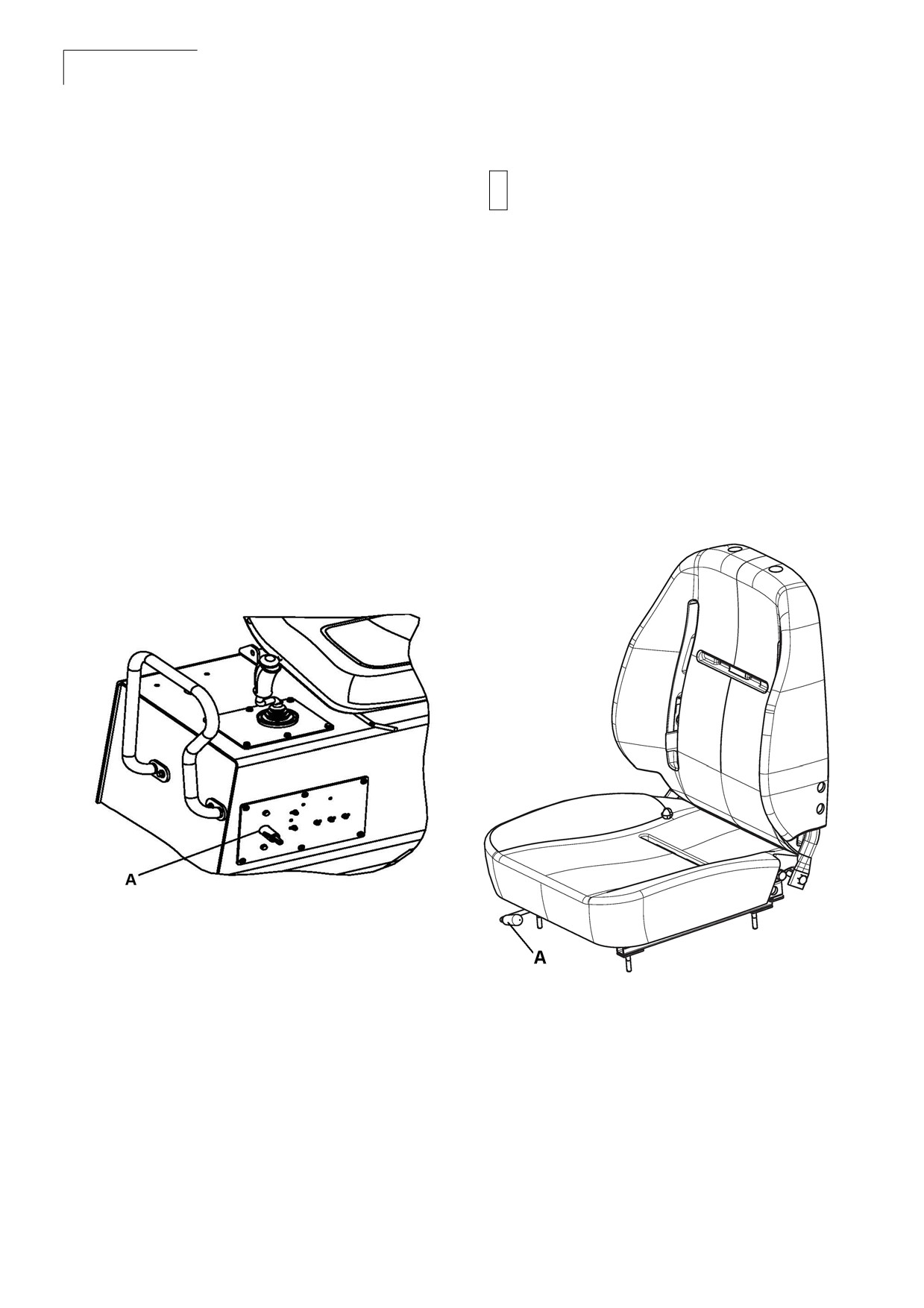
• Length adjustment: Pull the lever and move
the seat forward or back.
2. Turn the battery disconnecter key to switched
on position which is located on the right side of
the operator compartment. This supplies the
Figure 6-3:Seat Adjustments
roller with the power.
Figure 6-2:Battery Disconnecter
A Battery disconnecter
3. Check for warnings on the controls.
4. Start the engine from the operator position
only.
A Length adjustment
5. Avoid leaving the controls with the engine
running. Never leave the operator platform
while the roller is running.
CC 125
Inspections and Operations
37
Instruction Manual
Check the Instruments and Lamps
Note Make sure that the emergency stop is pulled out and the parking brake is activated. If
the forward/reverse lever is in neutral, the automatic brake function is engaged.
1. Turn the switch to on position.
2. Check that the warning lamps in the warning panel come on.
3. Set the sprinkler switch to the operating position and check that the system is functioning.
Interlock
The roller is equipped with interlock. The diesel engine switches off after 10 seconds, if the operator
gets off the seat during tramming. If the operator is not seated during tramming a buzzer goes on
unless the parking brake is activated.
N o t e If the diesel engine is switched off, then wait for 15 seconds to restart it. Turning the
ignition key to on position will not restart the engine during this period.
CC 125
38
Inspections and Operations
Instruction Manual
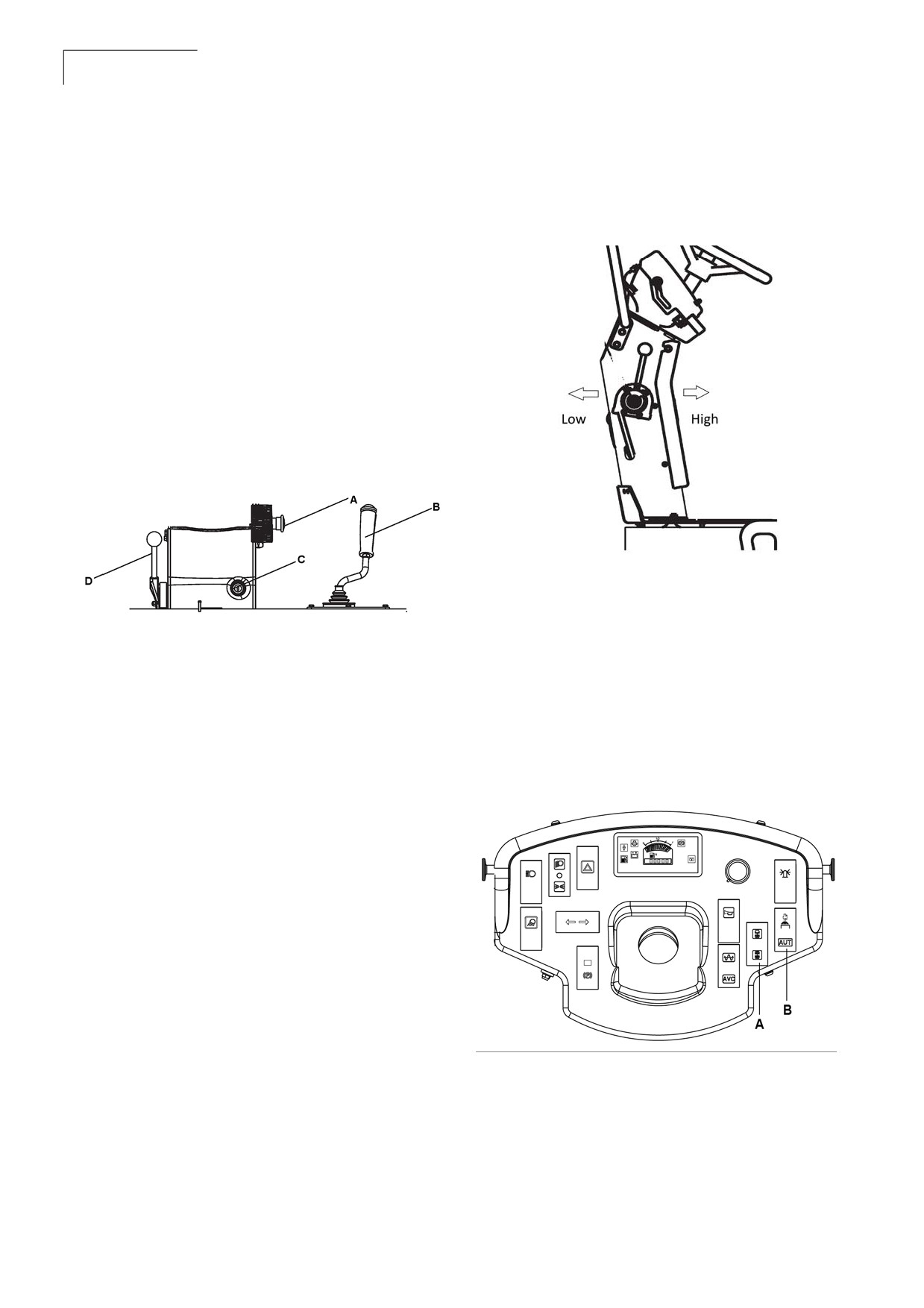
6. Make sure the throttle control is turned to low
6.3 Operating the Roller
position.
Operation
Figure 6-5:Throttle control
1. Before the roller startup, a pre-operational
general inspection of the roller must be
performed in accordance with those
instructions previously mentioned and in the
instructions found in
section 7 - Maintenance.
2. Make sure all operator console controls are
either off or in the neutral position and all
control console gauges read zero.
Figure 6-4:Operator Consoles
7. Set the vibration switch for manual/automatic
vibration position. In the manual position, the
operator must activate the vibration using the
switch on the forward/reverse lever grip. In the
A Emergency stop
C Ignition switch
automatic position, vibration is activated when
B FNR lever
D Throtlle lever
the pre-set speed is reached. Vibration is
automatically deactivated when the FNR lever
is moved from neutral condition.
3. Make sure the emergency stop button is not
activated.
4. The FNR must be in neutral position.
Figure 6-6:Vibration Man/Auto Switches
5. Parking brake switch must be in engaged
condition.
A Vibration man/
B Vibration selector
auto switch
switch
CC 125
Inspections and Operations
39
Instruction Manual
Note As a general rule, do not operate the
Vibration on One Drum
starter motor more than 30 seconds at
a time without pausing to allow the
1. Activate the vibration selector switch to select
starter motor to cool for at least 2
vibration with the rear drum only, or with two
minutes. Overheating caused by
drums.
excessive cranking will seriously
damage the starter motor.
2. Vibration selector is activated through the
switch in the FNR Lever.
8. Turn the ignition switch on, check all the
warning lamps and then crank the engine.
3. In the lower position the vibration is activated
on both drums.
9. Allow the engine to warm up at idle speed for
few minutes. Warm up time should be
4. In the upper position the vibration on the front
extended when extremely low ambient
drum is switched off.
conditions (cold weather) occur or when
battery power is depleted during initial start up.
Braking
10.Check the engine air cleaner indicator gauge
Normal Braking
to determine if the elements require servicing.
1. Turn the vibration off by pressing the vibration
11.Make sure the parking brake is released and
control button on the forward/reverse lever.
the parking lights goes off.
2. Set the forward/reverse control to the neutral
position and apply brake to stop the roller.
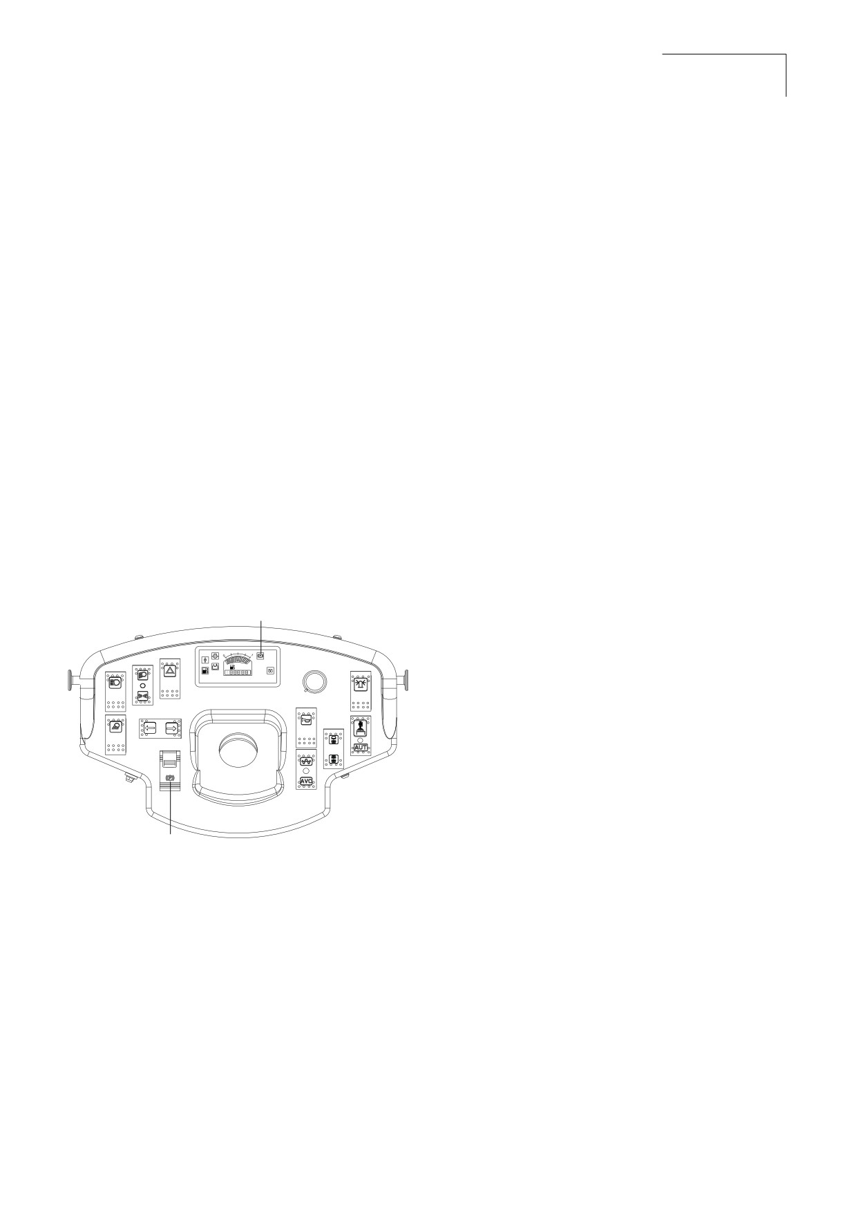
Figure 6-7:Parking Brake
Note In cold climatic condition braking
B
distances can be longer than the
1/2
normal distance.
A
Note Never leave the operator platform
without activating the parking brake.
Emergency Braking
To hold the machine in a stopped position
(parked), there is a mechanical parking brake on
each drum drive motor. The mechanical parking
A
brakes are spring-activated and hydraulically
released type brakes.
A
Parking brake button
B
Parking brake indicator
1. In case of emergency, push in the emergency
stop knob, hold the steering wheel firmly and
be prepared for a sudden stop. The diesel
engine stops.
2. After emergency braking, reset the forward/
reverse lever to neutral position, pull out the
emergency stop and activate the parking
brake. Restart the engine.
CC 125
40
Inspections and Operations
Instruction Manual
Switching Off
1. Press the vibration control button to off
position.
2. Set the forward/reverse control to the neutral
position.
3. Turn the throttle control to forward position and
allow the engine to idle for a few minutes to
cool.
4. Press the parking brake button to activate the
parking brake. Always activate the parking
brake before leaving the machine.
Note If the machine must be parked on a
sloping surface, chock the drums with
wedges to prevent any movement.
5. Check instruments and warning lamps to see
if any faults are indicated. Switch off all lights
and other electrical functions.
6. Turn the starter switch to the off position to
stop the engine.
7. Switch off the battery disconnecter and
remove the key.
CC 125
Inspections and Operations
41
Instruction Manual
Lifting the Roller
6.4 Lifting and Handling
• Use a crane/forklift to lift the equipment.
Locking the Articulation
• Pay attention when lifting and balancing the
Note Lock the steering joint, before lifting
equipment.
the roller.
• Seek a person to guide the way when lifting
1. Turn the steering wheel to the straight ahead
and moving the equipment.
position.
• An experienced crane/forklift driver should
2. Switch off the machine and activate the
drive the crane/forklift.
parking brake.
• When lifting, add a pad at the joint of steel
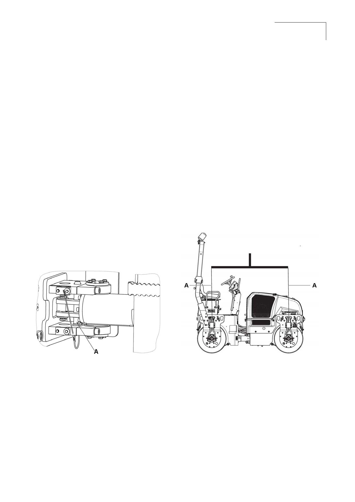
3. Pull down the galvanized lock bar from its
cable of the crane and the hook hole and
holder, and place it from underneath in the
secure the hole.
hole on the lower steering joint bracket.
Note The weight of the machine is shown
4. Press the bar until the upper end is visible in
on the lifting plate.
the hole on the upper steering joint bracket.
Refer to section 4 - Specifications.
5. Secure the bar with the lock pin.
Figure 6-9:Lifting the roller
Note Remember to refit the lock bar in its
holder after operation.
Figure 6-8:Locking the articulation
A Lifting plate
A Lock bar
CC 125
42
Inspections and Operations
Instruction Manual
Towing
6.5 Towing the Roller
The roller can be moved up to 300 meters
Towing Information
(1,000 ft) using the instructions below.
Proper equipment must be used to prevent
Note Chock the drum to prevent the roller
damage to the vehicle and the roller during any
from moving when the brakes are
tow. Follow the state and local laws applying to
hydraulically disengaged.
vehicles.
Release the Brakes
If the vehicle is to be towed by a wrecker, use only
equipment designed for this purpose following the
The disc brake in each drive motor must be
instructions of the wrecker manufacturer. A safety
disengaged mechanically, according to the
chain system must be used.
following instructions, before the roller can be
towed.
Personal injury or death could result
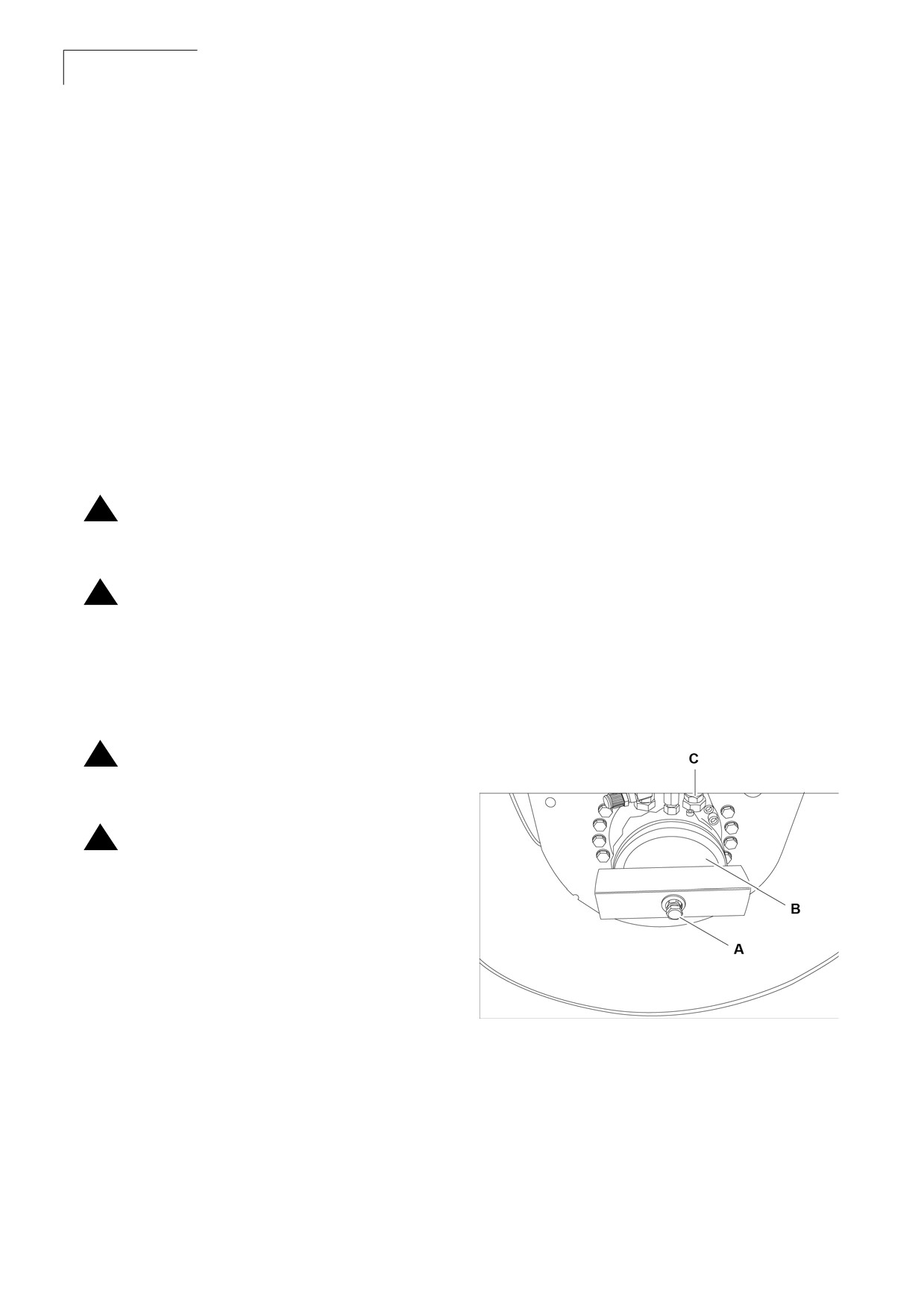
1. Remove the center plug using a screwdriver.
!
when towing a disabled roller incorrectly.
2. Screw off the brake tool from its threaded
fixing hole. Then fix the brake tool in the center
Block the drums of the roller to prevent
hole by tightening the screw until it bottoms in
!
movement before releasing the
the hole.
emergency brake system or the disc brake
in each drive motor must be disengaged
3. Tighten the nut against the brake tool until it
mechanically, before the roller can be
stops, indicating that the brakes is now
towed. The roller can roll free if drum is
disengaged.
not blocked.
Follow the recommendations below to
Figure 6-10: Left Side of Drum
!
properly perform the towing procedure.
Make sure to block the drums of the roller
!
and reapply the emergency brake system
before disconnecting from the towing
vehicle.
Note Maximum towing speed is 2 mph
(3 Kmph).
A Brake tool
C Disengagement nut
B Fastening screw
Note Make sure to secure the steering
wheel to maintain a straight-ahead
position.
CC 125
Inspections and Operations
43
Instruction Manual
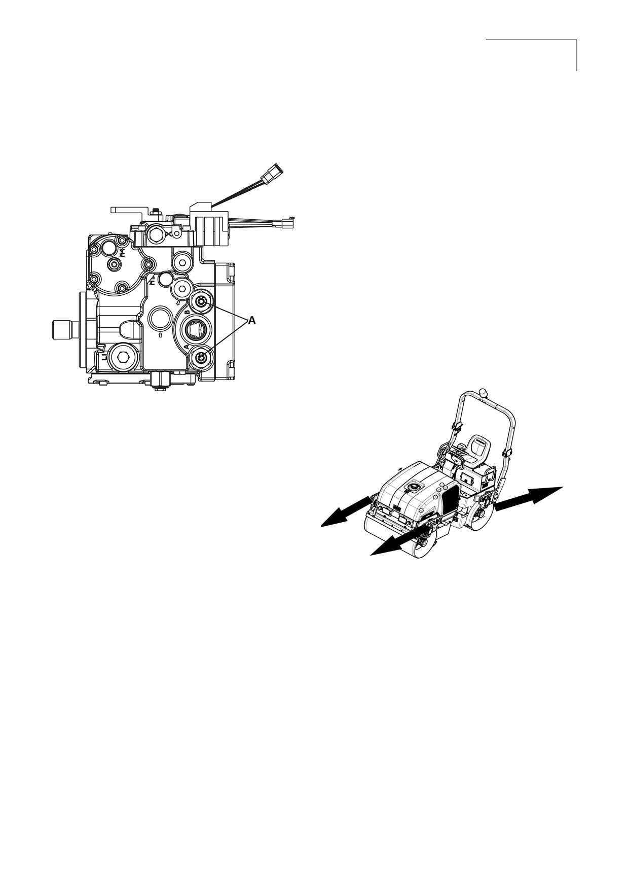
4. Slightly tap the plunger inside using a mallet.
Engaging the Brakes
1. Screw out the nut again after towing.
Figure 6-11: Plunger
2. Screw off the brake tool and fit it back into its
fixing holes
3. When machine is started, propulsion pump
plunger will automatically come out.
4. Refit the center plug to counteract the
information of rust inside the threaded hole.
5. When towing/retrieving a machine, the towing
device must be connected to both lifting holes.
The pulling force shall act longitudinally on the
machine. Maximum total pulling force 130 kN
(29225 lbf).
Figure 6-12:Towing
A Pluger
CC 125
44
Inspections and Operations
Instruction Manual
Start Up
6.6 Transporting the
Roller
1. Before starting the engine, check inside,
outside, and underneath the roller for people
or obstructions.
Transportation Procedures
2. Always horn before starting the roller to alert
Safety Precautions
everyone in the area.
Before moving the roller on public roads, check for
3. Check all the gauges (including fuel).
instructions and information with respect to traffic
regulations regarding construction machinery.
4. Check for excessive noise or vibration.
Before Driving
The roller must be driven and transported only in
accordance with the operating instructions.
1.
Fasten the seat belts.
1. When driving the roller, observe the prescribed
2.
Adjust each mirror so that the side of the
transport position, admissible speed, and
vehicle is visible in the side of the mirror
itinerary.
closest to the vehicle. This helps you
determine the relation to objects seen in the
2. Do not attempt to drive unless knowledgeable
mirror.
and experienced.
3.
Release the parking brake.
3. Always know the overall height, weight, width,
and length of the roller. Make sure there is
sufficient clearance when crossing
underpasses, bridges, and tunnels or when
passing under overhead lines.
4. When moving the roller on public access
roads, obey all traffic regulations and make
sure that proper clearance flags, lights, and
warning signs, including the slow moving
vehicle emblem, are properly displayed. Know
your approximate stopping distance at any
given speed. Never turn corners at excessive
speeds. Look in all directions before reversing
the direction of travel.
Operator Checklist
•
Make sure to know the vehicle and its equip-
ment and how to use it safely.
•
See that mirrors, and lights are clean and
unobstructed.
•
Check for fluid leaks.
•
Check lights and reflectors.
•
Check oil and coolant levels.
CC 125
Inspections and Operations
45
Instruction Manual
Securing for Loading
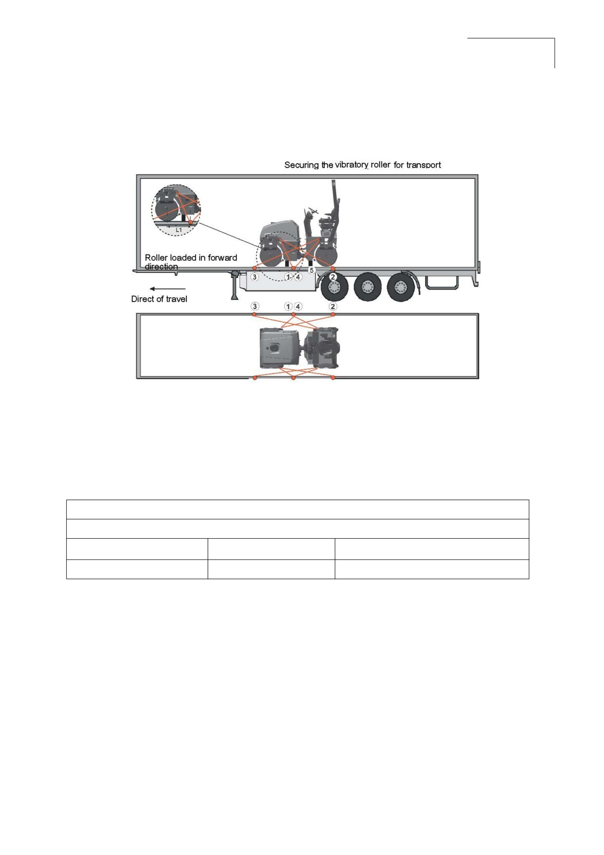
Figure 6-13:Securing for Loading
1,2
Double lashings, i.e. one lashing with two parts secured to two different lashing mounts.
3,4
symmetrically located on the right and left sides.
5
rubber
Table 1: Lashings' Permitted Distance
The lashings' permitted distance interval in meters
(1 - 4: Double lashings, LC at least 1.7 tonnes (1700 daN), STF 300 kg (300daN))
Double L1 - L2
Double L3 - L4
0,6 - 3,0
0,1 - 3,0
The distance L1 above is between points D and E. D is the projected point directly at right angles
laterally in relation to the edge of the platform from the lashing mount C on the roller. E is the lashing
mount at the edge of the platform. L2 - L3 have a corresponding relationship.
CC 125
46
Inspections and Operations
Instruction Manual
•
Lubricate the steering joint bearings and both
6.7 Special Conditions
bearings on the steering cylinder with
grease. Grease the steering cylinder piston
Cold Weather Conditions
with conservation grease. Grease the hinges
•
Refer to section 7 - 7.3 Refill Capacities/
on the doors to the engine compartment and
Lubricants in the maintenance section for
the cab. Grease both ends of the forward/
information regarding cold weather lubricants,
reverse control (bright parts).
hydraulic fluids, coolants, fuel, and the like.
•
Change all lubricants and fluids that may
•
Use winter grade diesel fuel for operation at
have deteriorated with use.
subzero temperatures.
•
Replace and secure all weatherproof covers.
•
Be extremely careful when using cold
weather starting aids. Starting aids are very
flammable and should only be used if
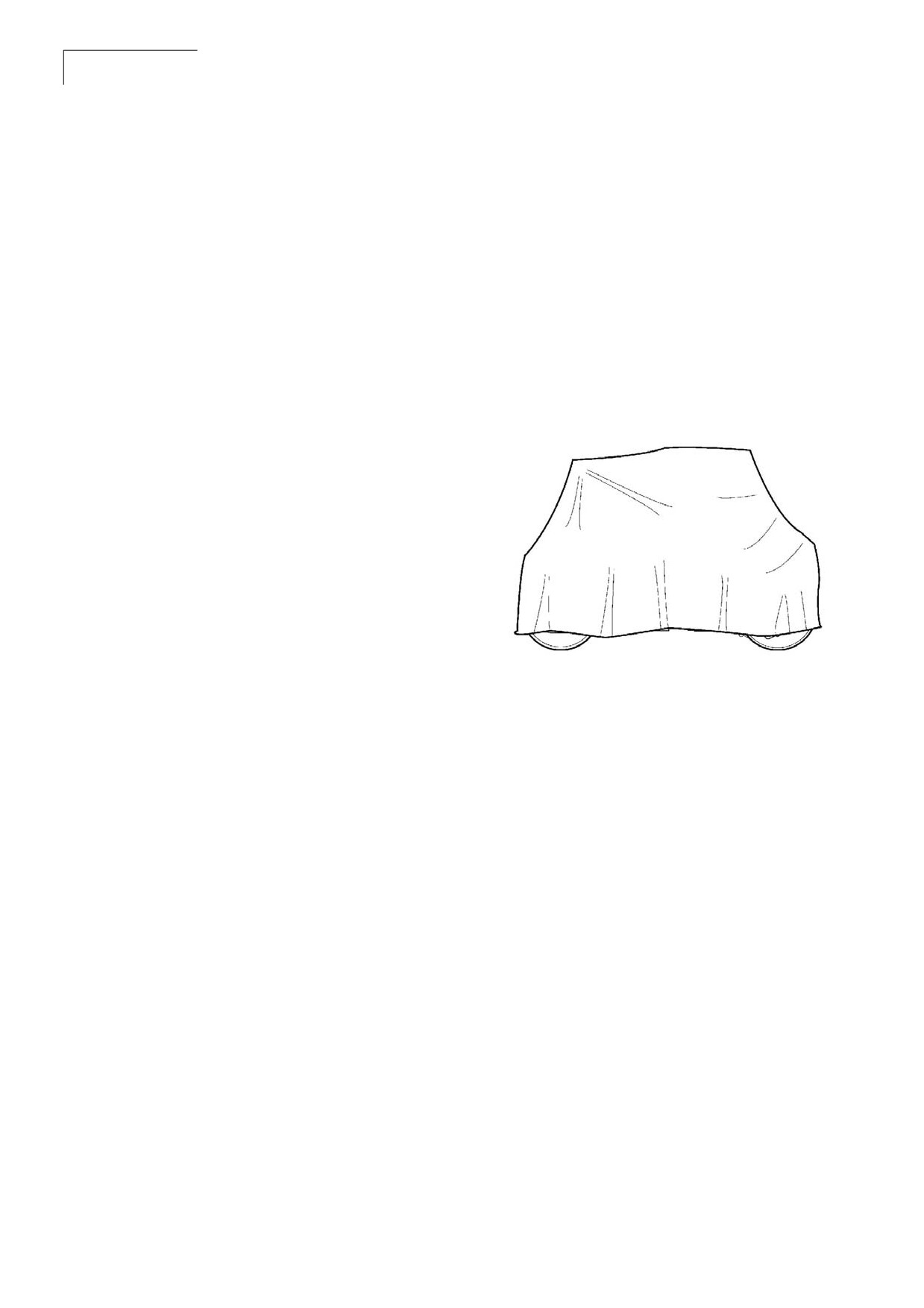
Figure 6-14:Long Term Parking
needed.
•
Remove batteries and store in a warm area to
about 68 °F (20 °C).
Hot Weather Conditions
•
Monitor temperature gauges.
•
Keep cooling fins on radiator and oil cooler
clean and free of accumulated dirt.
High Altitude Conditions
•
Be aware that engine power will be reduced.
•
Keep cooling fins on radiator and oil cooler
clean and free of accumulated dirt.
Long-term Parking
•
Observe the following when storing the roller
for short periods of time.
•
Remove the battery/batteries from the
machine, clean and charge once a month.
• Cover the air cleaner (Refer section 7 -
Maintenance) or its opening with plastic or
tape.
• Also cover the exhaust pipe opening. This is
to avoid moisture entering the engine.
• Fill the fuel tank completely full to prevent
condensation.
• Fill the hydraulic reservoir to the uppermost
level mark.
• Empty the water tank completely to avoid
fouling.
CC 125
Maintenance
47
Instruction Manual
Section 7:Maintenance
7.1 General Information
Safety should be the main concern for anyone working on or around the roller. Do not perform any
function that could put someone in danger.
Always wear proper safety gear while working on or around the roller. This includes an approved hard
hat, safety glasses, steel toe shoes, gloves, respirator, and ear protection. Do not wear loose fitting
clothing that can get caught in rotating components.
Note If not experienced with the roller controls and instruments, read and understand
Operation Controls.
The following operational hints are observed:
•
Do not speed the engine when it is cold.
•
Always chock the drum if there is a possibility of uncontrolled movement.
•
Do not lubricate the roller while the engine is running.
•
Always perform safety checks prior to starting and using the roller.
•
Always operate the roller at the full engine power.
•
Never propel or stop the roller on a slope or surface that could possibly collapse.
•
Never stop the roller against a high wall that could possibly collapse or cause a crushing risk.
•
Before starting the engine all the controls are in the off or neutral position on the operator control
panel.
•
Always sound the attention horn before moving the roller in either direction to alert personnel and
allow sufficient time before putting the roller in motion.

CC 125
48
Maintenance
Instruction Manual
7.2 Maintenance Schedule
Maintenance Schedule Information
The maintenance schedule shows those items requiring regular service and the interval at which they
are performed. A regular service program is geared to the items listed under each interval. These
intervals are based on average operating conditions. Before each consecutive interval is performed, all
of the maintenance requirements from the previous interval must also be performed.
N o t e In the event of extremely severe, dusty, or wet operating conditions, more frequent
maintenance than specified is necessary.
Table 7-1: Maintenance Daily/Every 8 Hours
Description
Action
Lubrication
Engine oil
Check
Outer air cleaner element
Check
Radiator coolant
Check
Hydraulic Oil
Check
Greasing
Grease
See lubrication chart
Table 7-2: Maintenance at First 50 Hours
Description
Action
Lubrication
Engine oil filter element
Change
See engine manual
Engine oil
Change
See engine manual
Fuel filter element
Change
See engine manual
Mud filter
Change
See engine manual
Hydraulic oil filter
Change
Table 7-3: Maintenance at 50 Hours or Weekly
Description
Action
Lubrication
Alternator belt
Check
Water separator
Drain
AVM Bolts
Check
CC 125
Maintenance
49
Instruction Manual
Table 7-4: Maintenance at 250 Hours/750 Hours/Three Months
Description
Action
Lubrication
Engine Oil filter element
Change
See engine manual
Engine oil
Change
See engine manual
Fuel filter element
Change
See engine manual
Mud filter
Change
See engine manual
ROC cleaning
Clean
Fuel pipe and clamps
Check
Intake air line
Check
Drum oil
Check
Battery
Check
Table 7-5: Maintenance at 500 Hours/Six Months
Description
Action
Lubrication
Engine oil filter element
Change
See engine manual
Engine Oil
Change
See engine manual
Fuel filter element
Change
See engine manual
Mud filter
Change
See engine manual
Outer air cleaner element
Change
Inner air cleaner element
Change
Alternator belt
Check
See engine manual
Fan belt
Check
See engine manual
ROC Cleaning
Clean
Fuel pipe and clamps
Check
Intake air line
Check
CC 125
50
Maintenance
Instruction Manual
Table 7-6: Maintenance at 1,000 Hours/One Year
Description
Action
Lubrication
Engine oil filter element
Change
See engine manual
Engine oil
Change
See engine manual
Fuel filter element
Change
See engine manual
Mud filter
Change
See engine manual
Alternator belt
Check
See engine manual
Fan belt
Check
See engine manual
Valve cover gasket
Change
See engine manual
Radiator coolant
Change
ROC cleaning
Clean
Fuel pipe and clamps
Check
See engine manual
Intake air line
Check
Valve clearance
Check
See engine manual
Hydraulic oil filter
Change
Drum oil
Change
Table 7-7: Maintenance at 2,000 Hours/Two Years
Description
Action
Lubrication
Engine oil filter element
Change
See engine manual
Engine oil
Change
See engine manual
Fuel filter element
Change
See engine manual
Mud filter
Change
Outer air cleaner element
Change
Inner Air cleaner element
Change
Alternator belt
Check
See engine manual
Fan belt
Check
See engine manual
Valve cover gasket
Change
See engine manual
Radiator coolant
Change
ROC cleaning
Clean
Fuel pipe and clamps
Check
See engine manual
Intake air line
Check
Valve clearance
Check
See engine manual
CC 125
Maintenance
51
Instruction Manual
Description
Action
Lubrication
Hydraulic oil
Change
Hydraulic oil filter
Change
Drum oil
Change
Drum AVM
Change
CC 125
52
Maintenance
Instruction Manual
7.3 Refill Capacities/Lubricants
General Information
Lubrication is an essential part of preventive maintenance, affecting to a great extent the useful life of
the unit. Periodic lubrication of the moving parts reduces to a minimum the possibility of the mechanical
failures.
The lubrication chart that follows in this section shows those items requiring regular service and the
interval at which they should be performed. Details concerning the oil and other lubricants follow the
lubrication chart. A regular service program should be geared to the items listed under each interval.
These intervals are based on the average operating conditions. In the event of extremely severe, dusty,
or wet operating conditions, more frequent lubrication than specified may be necessary.
•
Specific recommendations of the brand and grade of lubricants are not made here due to regional
availability, operating conditions, and also the continual development of the improved products.
For more information, refer to component manufacturer’s manual.
•
All the oil levels are to be checked with the roller parked on a level surface and while the oil is cold,
unless otherwise specified.
•
On plug type check points, the oil levels are to be at the bottom edge of the check port.
•
All the grease fittings are SAE standard unless otherwise indicated. Grease the non-sealed fittings
until the grease is seen extruding from the fitting. One ounce (28 grams) of EP-MPG equals one
pump on a standard one pound (0.45 kg) grease gun.
•
Over lubrication on the non-sealed fittings will not harm the fittings or components, but under-lubri-
cation will definitely lead to a shorter lifetime.
•
Grease fittings that are worn and do not hold the grease gun or those that have a stuck check ball
must be replaced.
To prevent the minor irregularities from developing into serious conditions, several other services or
checks are recommended for the same intervals as the periodic lubrication:
•
Thoroughly wash all the fittings, caps, plugs, and the like with a non-flammable and non-toxic clea-
ning solution before servicing to prevent dirt from entering while performing the service. During the
regular lubrication service, visually check the entire unit with regard to capscrews, nuts, and bolts
being properly secured.
•
Spot check the several capscrews and the nuts for proper torque. If any are found loose, a more
thorough investigation must be made.
•
If a defect is detected, that requires special service, stop the roller operation until the defect has
been corrected. If necessary, contact the Atlas Copco representative for assistance.

CC 125
Maintenance
53
Instruction Manual
Lubrication Chart
Periodic lubrication requirements are listed in the following Lubrication Chart. These requirements
include lubricant checks and greasing designated areas of the roller.
Description
Part Number
Remarks
Quantity
Engine oil
5580020624
Atlas Copco engine 100
5 L (1.3 gallons)
Hydraulic oil
9106230330
Atlas Copco hydraulic 300
20 L (5.3 gallons)
Drum oil
4812030756
Dynapac Gear oil 300
5 L (1.3 gallons)
Coolant
2658326217
Coolant
20 L (5.2 gallons)
Refill Capacities
The following fluid capacities are provided for the servicing personnel who must perform roller
maintenance in the remote locations where complete shop facilities and resources are not available.
These capacities will give the servicing personnel an approximation of the fluid capacities of the
components to be serviced. Always use the specified method to check for accurate fluid levels.
Component
Approx. Quantity
Systems
Hydraulic Tank
45 L (11.9 gallons)
Engine
Engine Coolant
12L (13.17 gal) Coolant + 8L (2.1 gal) Water
Engine Oil Capacity
10 L (2.6 gallons)
Fuel Tank
50 L (13.2 gallons)
Drum
5 L (1.3 gallons)
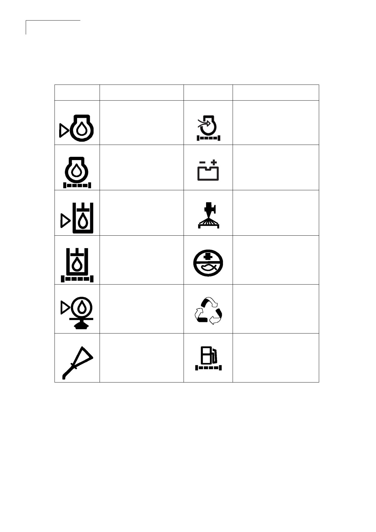
CC 125
54
Maintenance
Instruction Manual
Table 7-8: Maintenance Symbols
Symbol
Description
Symbol
Description
Engine oil level
Air filter
Engine oil filter
Battery
Hydraulic reservoir level
Sprinkler
Hydraulic fluid filter
Sprinkler water
Drum oil level
Recycling
Lubrication oil
Fuel filter

CC 125
Maintenance
55
Instruction Manual
7.4 Standard Torque Values
Use only the proper tools (inches) on hardware. Other tools may not fit properly and may slip
!
and cause injury.
Head Markings
Fasteners should be replaced with the same grade or a higher grade. If higher grade fasteners are
used, these should only be tightened to the strength of the original grade fastener.
Do not use these values if a different torque value or the tightening procedure is listed for a specific
application. Torque values listed are for general use only. All values are suggested maximum with dry
plated hardware.
Make sure fastener threads are clean and you properly start thread engagement. This will prevent them
from falling when tightening.
The following pages list the recommended tightening torques for the various size bolts used for the
machine. Proper torque specifications should be used at all times.
Recommended Torques
This page lists the recommended tightening torques, in foot/pounds (ft·lb), for the various size bolts and
nuts that are used. Proper torque specifications should be used at all times. Dry means clean dry
threads and lube means a light film of oil. Excess oil in a threaded dead end hole can create a hydraulic
lock giving false torque readings. Suggested assembly torque values are per engineering
specifications.
Metric coarse screw thread, bright galvanized (fzb):
M-thread
Size
12.9,
8.8 Oiled
8.8 Dry
10.9 Oiled
10.9, Dry
12.9, Dry
Oiled
M6
8,4
9,4
12
13,4
14,6
16,3
M8
21
23
28
32
34
38
M10
40
45
56
62
68
76
M12
70
78
98
110
117
131
M14
110
123
156
174
187
208
M16
169
190
240
270
290
320
M20
330
370
470
520
560
620
M22
446
497
626
699
752
839

CC 125
56
Maintenance
Instruction Manual
Metric coarse screw thread, bright galvanized (fzb):
M-thread
Size
12.9,
8.8 Oiled
8.8 Dry
10.9 Oiled
10.9, Dry
12.9, Dry
Oiled
M24
570
640
800
900
960
1080
M30
1130
1260
1580
1770
1900
2100
Metric coarse thread, zinc-treated
(Dacromet/GEOMET)
M-thread Size
10.9 Oiled
10.9 Dry
12.9 Oiled
12.9 Dry
M6
120
150
146
183
M8
28
36
34
43
M10
56
70
68
86
M12
98
124
117
147
M14
156
196
187
234
M16
240
304
290
360
M20
470
585
560
698
M22
626
786
752
944
M24
800
1010
960
1215
M30
1580
1990
1900
2360
Bolt dimensions
M16 (PN 902889)
Strength class
10.9
Tightening torque
192 Nm, torque class 2
(Dacromet treated)
CC 125
Maintenance
57
Instruction Manual
Loose Bolted Connections
7.5 Maintenance as
Required
If any loose nuts or bolts are found during the
frequent walk-around and the daily inspections,
make sure they are properly torqued. Refer to 7.4
Service as Required
Standard Torque Values for the required torque
The preventive maintenance and service in this
for all bolt sizes and grades. Always replace self-
section requires attention on the need basis,
locking nuts if they have been loosened.
before, during, and after the operation shift. This
is in addition to the 8 to 10 hour daily routine
Air Cleaners
maintenance procedures. Performance of this
inspection can result in longer life and maximum
The following are detailed instructions for
productivity from the roller. Refer to the
performing routine maintenance procedures on
manufacturer’s service manuals for maintenance
the air cleaner.
and service on the carrier.
Raw, unfiltered air can damage the
Clean the Roller
!
roller. Never service the air cleaner
while the roller is running.
The complete roller must be given a weekly
cleaning. Daily cleaning will be required if material
is adhering to the machine working parts.
Airborne dust may be hazardous. Wear
!
proper personal protective equipment
•
Make sure the operator areas, steps, and
while handling air cleaners and
grab rails are clean. Oil, grease, snow, ice, or
elements.
mud in these areas can cause to slip and fall.
Clean the boots of excess mud before getting
in the roller.
Air Cleaner Indicators
•
Thoroughly wash all fittings, caps, plugs, and
Check the air cleaner visual restriction indicator
the like with a nonflammable, nontoxic clea-
before and after every shift.
ning
solution before servicing to prevent dirt from
entering while performing the service.
If the indicator on the air cleaner turns red, replace
•
After cleaning, check for defects in the air cle-
the main filter on the air cleaner. The dust pouch
aner ducts.
is emptied by pressing the rubber bellows with
your fingers. Check also that the air hoses are in
a. Check intake for accumulation of
good condition. Clean the air cleaner when
debris that could restrict air flow.
operated in extremely dusty environments.
b. Check the air cleaner mounting
hardware for security.
c. Check all hoses for cracks, chafing, or
deterioration and replace at the first
sign of probable failure.
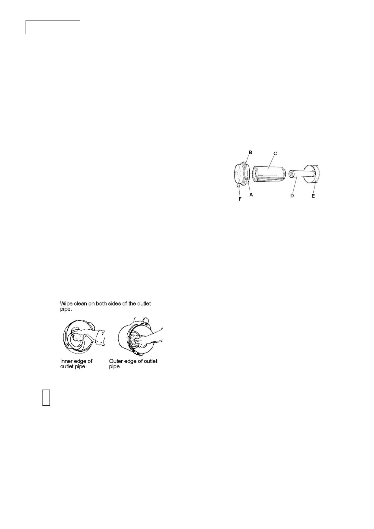
CC 125
58
Maintenance
Instruction Manual
Connections and Ducts
Air Cleaner Main Filter
Check air cleaner and ducts for leaks before every
The air cleaner is the dry type with two elements;
shift, during every shift, and after every shift. Make
a main filter that is replaceable and can be
sure all connections between the air cleaner and
cleaned, and a backup filter that should only be
air compressor are tight and sealed.
replaced and never cleaned.
Note Dust that gets by the air cleaner
system can often be detected by
Figure 7-2: Air Cleaner Elements
looking for dust streaks on the air
transfer tubing or just inside the intake
manifold inlet.
Air Cleaner Pre-Cleaner
Wipe clean the inside of the cover and the filter
housing. Wipe also both surfaces for the outlet
pipe.
A Clips
D Backup filter
B Cover
E
Filter housing
Note Check that the hose clamps between
C Main filter
F
Dust valve
the filter housing and the suction hose
are tight and that the hoses are intact.
Inspect the entire hose system, all the
When the visual restriction indicator is red, clean
way to the engine.
and replace the air cleaner elements. The
following maintenance procedure must be
followed.
Figure 7-1: Pre-Cleaner
1. Unclip the clamps holding the main filter.
2. Remove the washer. Carefully withdraw the
main filter.
3. Inspect the main filter indicator (safety
signal). If the indicator is red, replace the
main filter.
Note Make sure new elements arrive
enclosed in plastic or in a protective
Never clean Donoclone tubes with
membrane. Do not install elements
!
compressed air unless both the safety
that are unprotected. This is a dust
and primary elements are installed in the
hazard.
air cleaner. Do not steam clean the tubes
N o t e Never attempt to clean a backup filter.
in the pre-cleaner.
Change the backup filter whenever
main filter replaced.
4. Examine the new or newly cleaned main filter
for torn or damaged pleats, bent end covers,
liners, and gaskets.
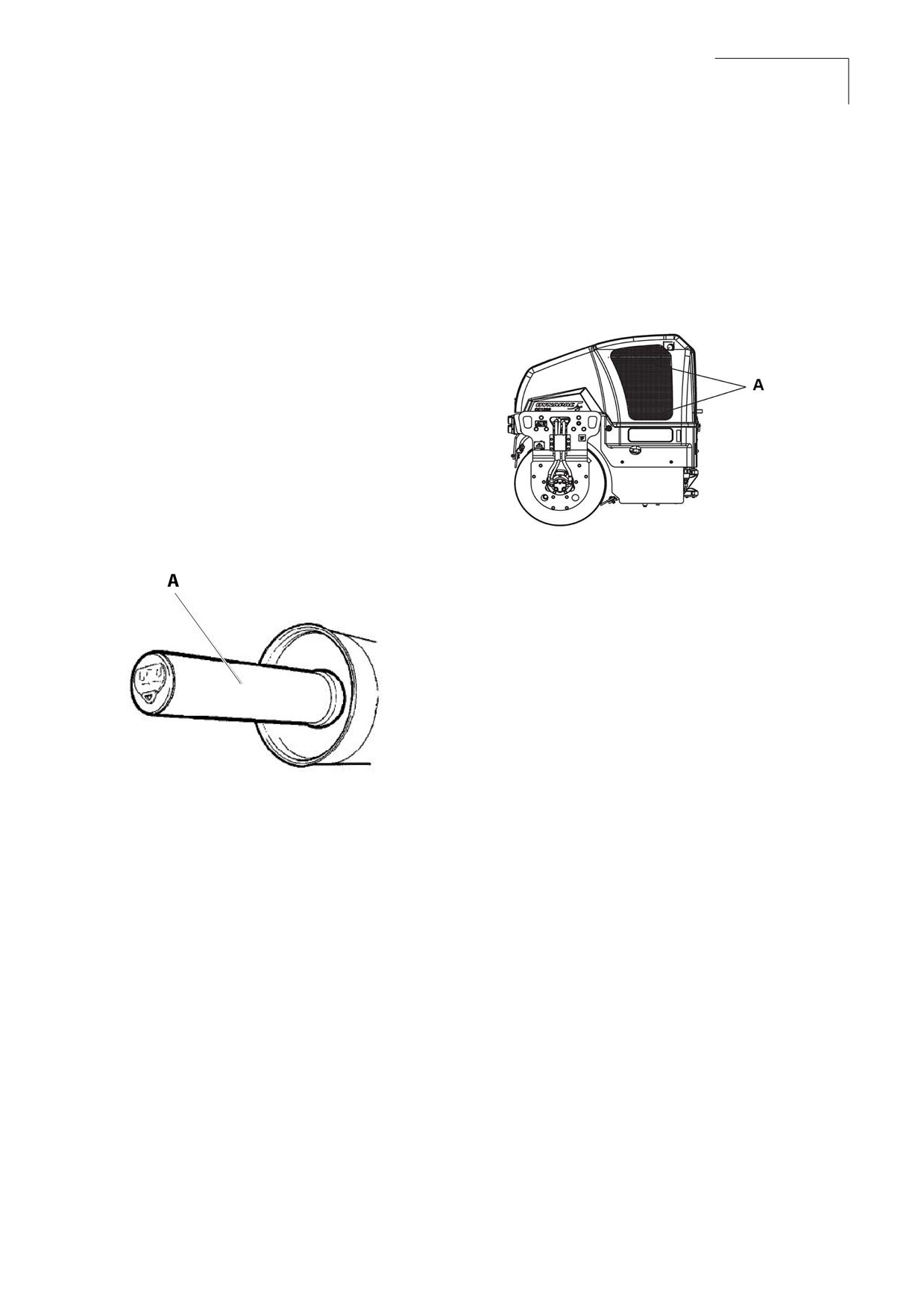
CC 125
Maintenance
59
Instruction Manual
5. Make sure the main filter washer are not
Air Circulation
cracked or damaged. Replace if necessary.
Check that the engine has free circulation of
6. The backup filter should be replaced if the air
cooling air through the grille in the engine
cleaner visual restriction indicator is red after
compartment.
servicing the main filter.
7. Clean the inside of the air cleaner housing
before removing backup filter.
Figure
7-4: Air Circulation
8. To replace the backup filter, remove the old
filter from the holder. Dispose of the used
element properly.
9. Install new backup filter into the holder.
10. Carefully install the cleaned or new main
filter.
Figure 7-3: Air Filter
A
Cooling air grille
Hose and Clamps
1. Periodic clamping bolts re-tightening is
necessary due to cold-flow present in all
rubber hoses. Tighten the boss clamps.
2. Examine and change out worn hoses and
weakened Boss clamps. If hoses are to be
A
Backup filter
changed out, change the Boss clamps also.
Boss clamps hold the hose connections
under a large amount of pressure. Boss
11. Re-install the back cover, make sure the dust
clamps (including nuts and bolts) are for
valve is positioned downwards.
single use only. Do not reuse. Once
removed, discard them.
12. Inspect all air intake piping and joints
between the air cleaner and inspect the air
inlet to make sure that no dusty air can enter.
After servicing the elements, reset the restriction
indicator to green when the element is replaced in
the air cleaner housing.
Note Never leave the air cleaner open
longer than necessary.
Note The two most common servicing
problems are over servicing and
improper servicing.
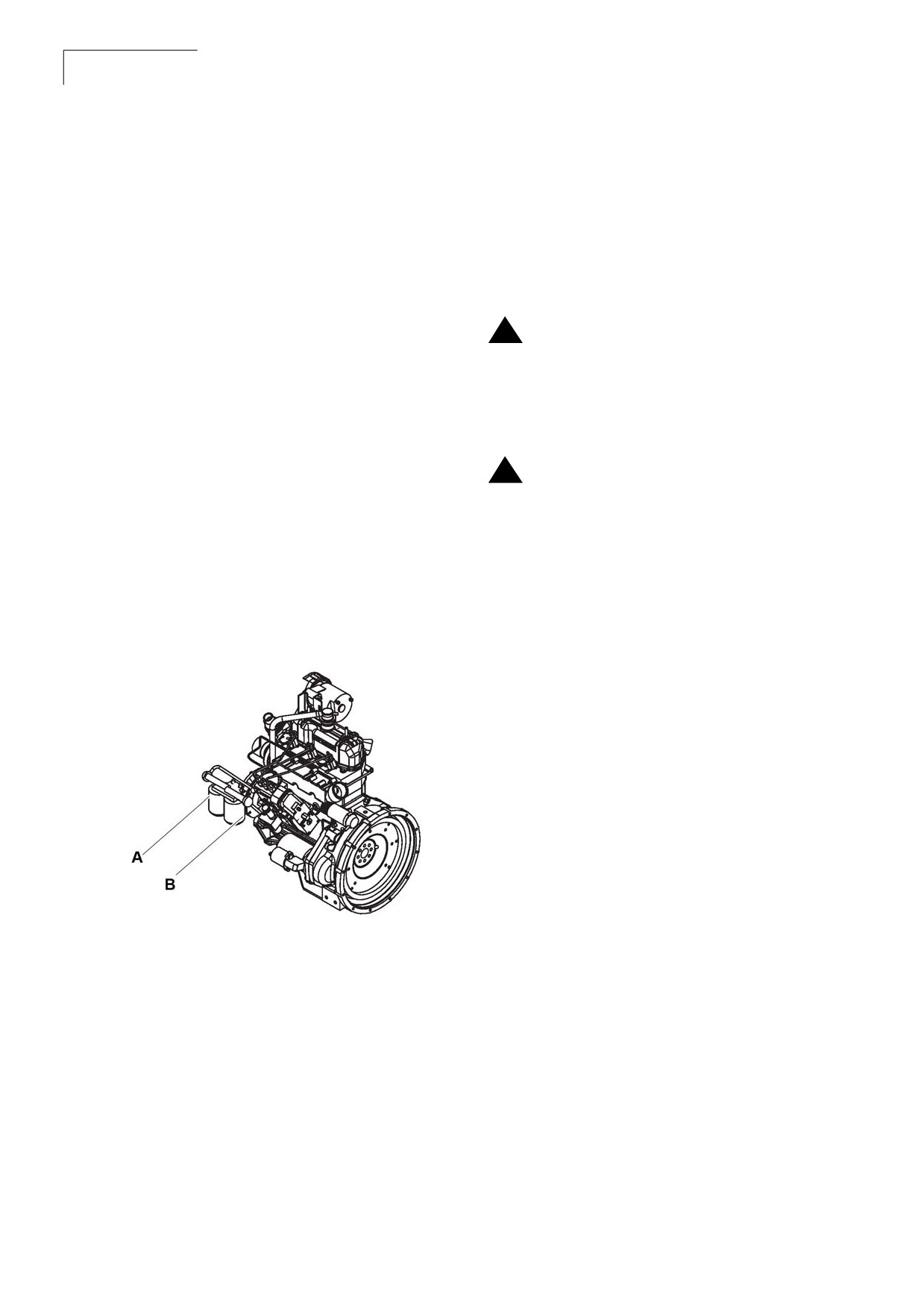
CC 125
60
Maintenance
Instruction Manual
Engine
Batteries
Refer to the engine service and maintenance
The following battery maintenance must be
manuals for specific information on the engine
carried out as part of the 250 hour routine
maintenance.
maintenance schedule.
Note Switch off the engine before filling the
oil.
Batteries contain an acid and can cause
!
injury. Skin and eye contact with battery
Note Care must be taken while draining the
fluid can cause injury. Avoid skin and eye
oil. Wear protective gloves and eye
contact with battery fluid. If contact
glasses.
occurs, flush area immediately with
water.
1.
Change the engine oil after 250 hours of
operation.
Battery fumes can ignite and explode. Do
!
not smoke when observing battery fluid
2.
Remove the oil filler cap and oil drain plug.
level.
Drain the oil into a suitable container.
N o t e When disconnecting the battery,
3.
Reinstall the drain plug and tighten.
always disconnect the negative cable
first. When connecting the battery,
4.
Remove and replace the oil filter.
always connect the positive cable first.
Note Always wear protective glasses when
working with batteries. Wash hands
Figure 7-5: Fuel Filters
after touching batteries and
connectors. Use of gloves
recommended.
Batteries, Clamps, and Cables
The standard batteries supplied are heavy duty
lead acid type, requiring the following
maintenance.
1. Keep the top of the batteries clean.
2. Clean the terminals.
A
Mud filter
3. Keep battery connections tight.
B
Fuel filter
4. Apply a small amount of grease to the
terminal connections to prevent corrosion.
5.
Remove the oil filler cap and fill the engine
crank case with recommended oil.
5. Inspect the cables, clamps, and hold down
brackets. Replace if necessary.
6.
Start the engine and allow it to idle for a few
minutes. During this time, check around the
oil filter and drain plug for leaks.
7.
Install the oil filler cap.
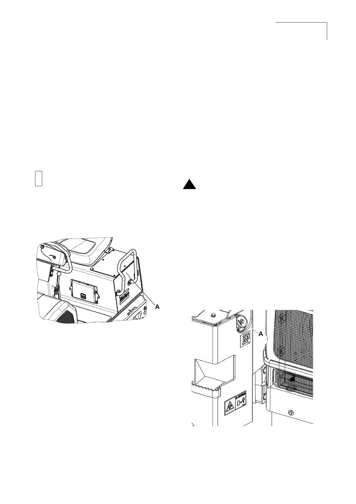
CC 125
Maintenance
61
Instruction Manual
Check Electrolyte Level
Fuel Tank
1.
Shut off the engine.
Refuel every day before starting to work.
2.
Lockout/tagout the roller as per the site
specific procedure.
1. Screw off the lockable tank cap.
3.
Check the electrolyte level and keep the
2. Fill diesel fuel to the lower edge of the fil-
electrolyte level above the plates. Fluid level
ler pipe.
is low when below ring or ring is visible and
too high when slots are not visible.
Check fuel tanks and fuel lines for possible leaks.
Because of the potential fire hazard, leaks must
4.
Refill with distilled water, if necessary.
be corrected as soon as they are spotted.
Over filling can cause poor performance
!
or early failure.
Fuel is flammable. May cause serious
!
injury or death. Shut off the engine,
extinguish all open flames, and do not
smoke while filling the fuel tanks. Always
wipe up any spilled fuel immediately.
5.
Remove lockout / tagout.
Check the fuel level by reading the fuel level
Figure 7-6: Battery Location
gauge.
Never allow fuel tanks to completely empty.
Fill tank with the correct grade of fuel.
The fuel tank holds 50 liters.
Figure 7-7: Fuel Tank
A
Battery location
A
Fuel tank
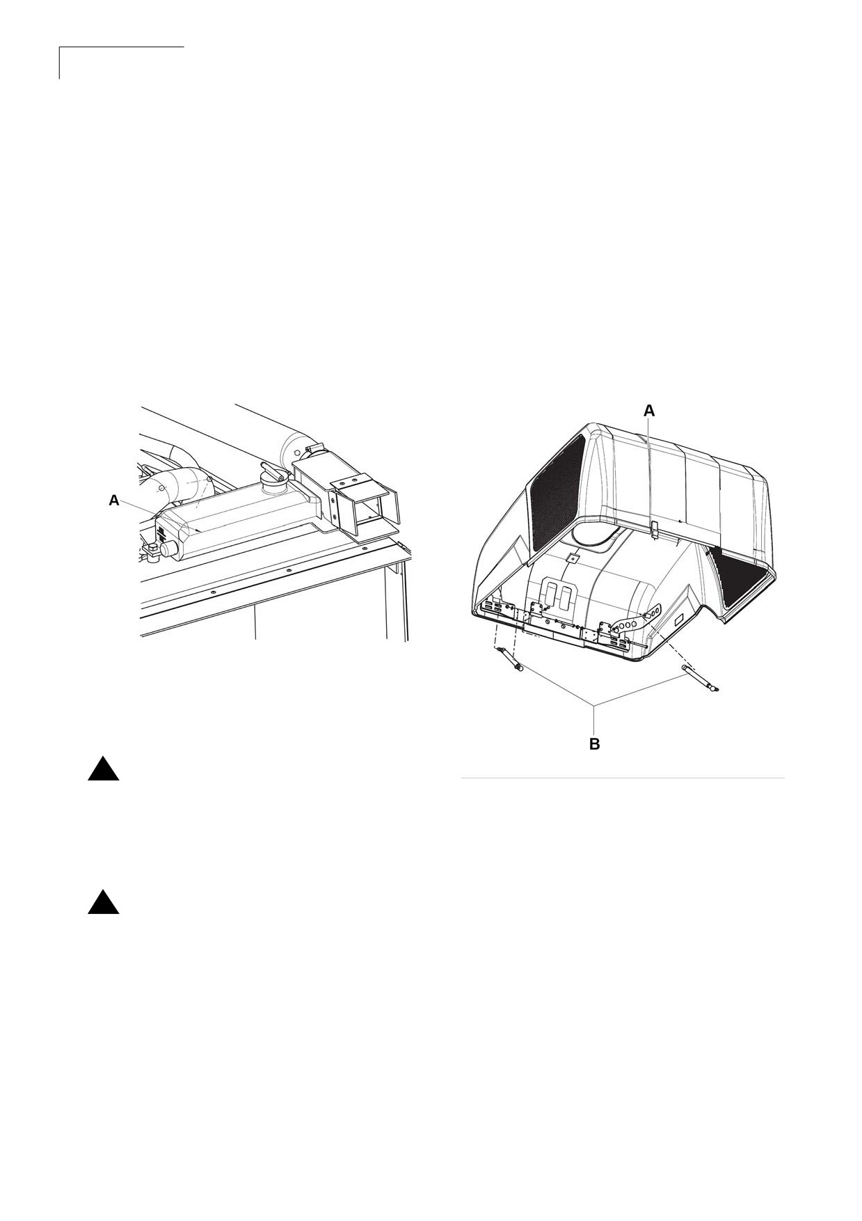
CC 125
62
Maintenance
Instruction Manual
Coolant System
Lowering of Engine Hood
1. Stand on the left side of the engine hood.
Check that all hoses/hose connectors are intact
and tight. Fill with coolant as specified in the
2. Press in the black rod and carefully lower the
lubricants specification.
engine hood until the gas spring goes into
the slot.
Change the coolant every year. Failure to cool the
3. Release the black rod and then lower down
engine properly can result in engine failure or
the engine hood completely.
severely reduce engine life.
Figure 7-9: Lowering the Hood
Figure 7-8: Coolant Level Guage
A Coolant level guage
Personal injury can occur when removing
!
the radiator cap. Steam or fluid escaping
from the radiator can burn. Inhibitor
contains alkali. Avoid contact with skin
and eyes. Wear protective gloves and
A Engine hood
B Gas spring
eye glases.
Always shut off the engine and allow it to
!
cool down before removing the radiator
cap. Remove the radiator cap slowly to
relieve pressure. Avoid contact with
steam or escaping fluid.
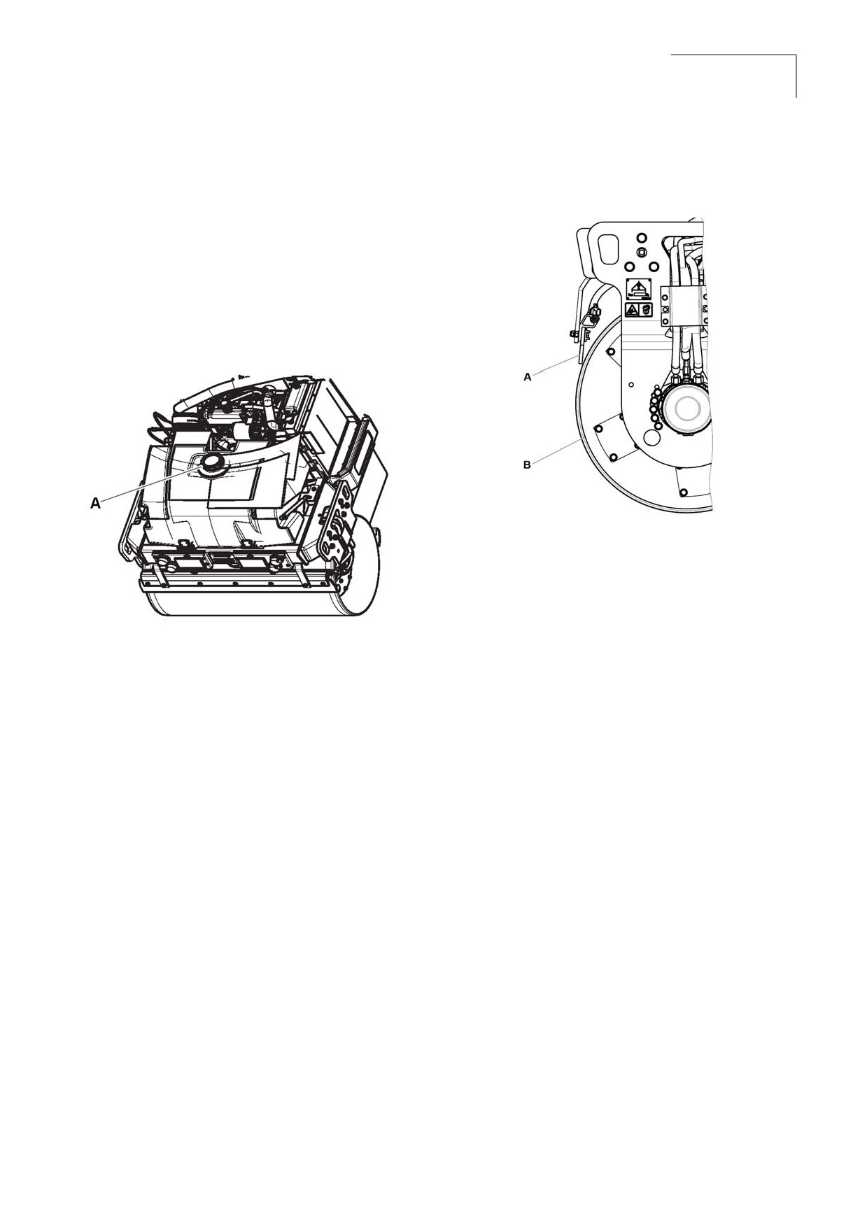
CC 125
Maintenance
63
Instruction Manual
Water Tank
4. Tighten all the screws after adjustment.
Unscrew the tank cap and fill with clean water. Do
Figure 7-11: Drum
not remove the strainer. See technical
specifications for the tank volume.
Note A small amount of environment-
friendly antifreeze is added.
Figure 7-10: Water Tank
A Scraper blade
B Drum
The scrapers must be lifted from the drum during
transport.
Brakes
A
Tank cap
Run the roller very slowly forward. Hold the
steering wheel firmly and brace yourself for a
Fixed Scrapers
sudden stop. Press in the emergency stop. The
roller will stop abruptly and the engine will switch
Make sure that the scrapers are undamaged.
off. After testing the brakes, set the forward/
Adjust the scrapers so that they are 1-2 mm from
reverse lever in neutral. Pull out the emergency
the drum. For special asphalt compounds, it may
stop. Start the engine. The roller is now ready for
be better if the scraper blades lie lightly against
operation.
the drums.
Asphalt remnants can accumulate on the scraper
and affect the contact force. Clean as required.
1. Loosen the screws to adjust the contact
pressure of the scraper blade against the
drum.
2. Lock this setting by tightening the lock nut
against the mounting plate.
3. Adjust the contact surface on both scraper
attachments.
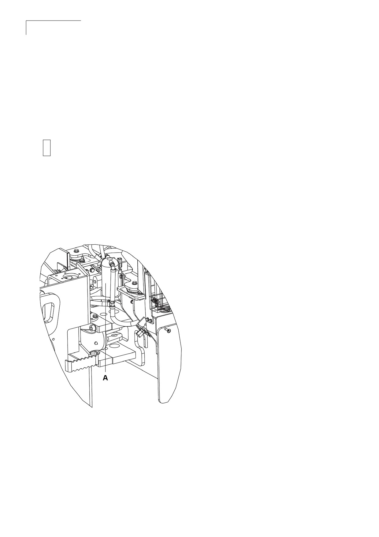
CC 125
64
Maintenance
Instruction Manual
Sprinkler System
Start the sprinkler system and make sure that
nonozzles are clogged. If necessary, clean
clogged nozzles and the coarse filter located by
the water pump.
The sprinkler system should be drained if
!
there is a risk of freezing.
Wear protective eye glases when working
with compressed air.
Dismantle the blocked nozzle by hand. Blow the
nozzle and fine filter clean with compressed air, or
install replacement parts and clean the clogged
parts later.
Figure 7-12: Sprinkler Pump
A Sprinkler pump
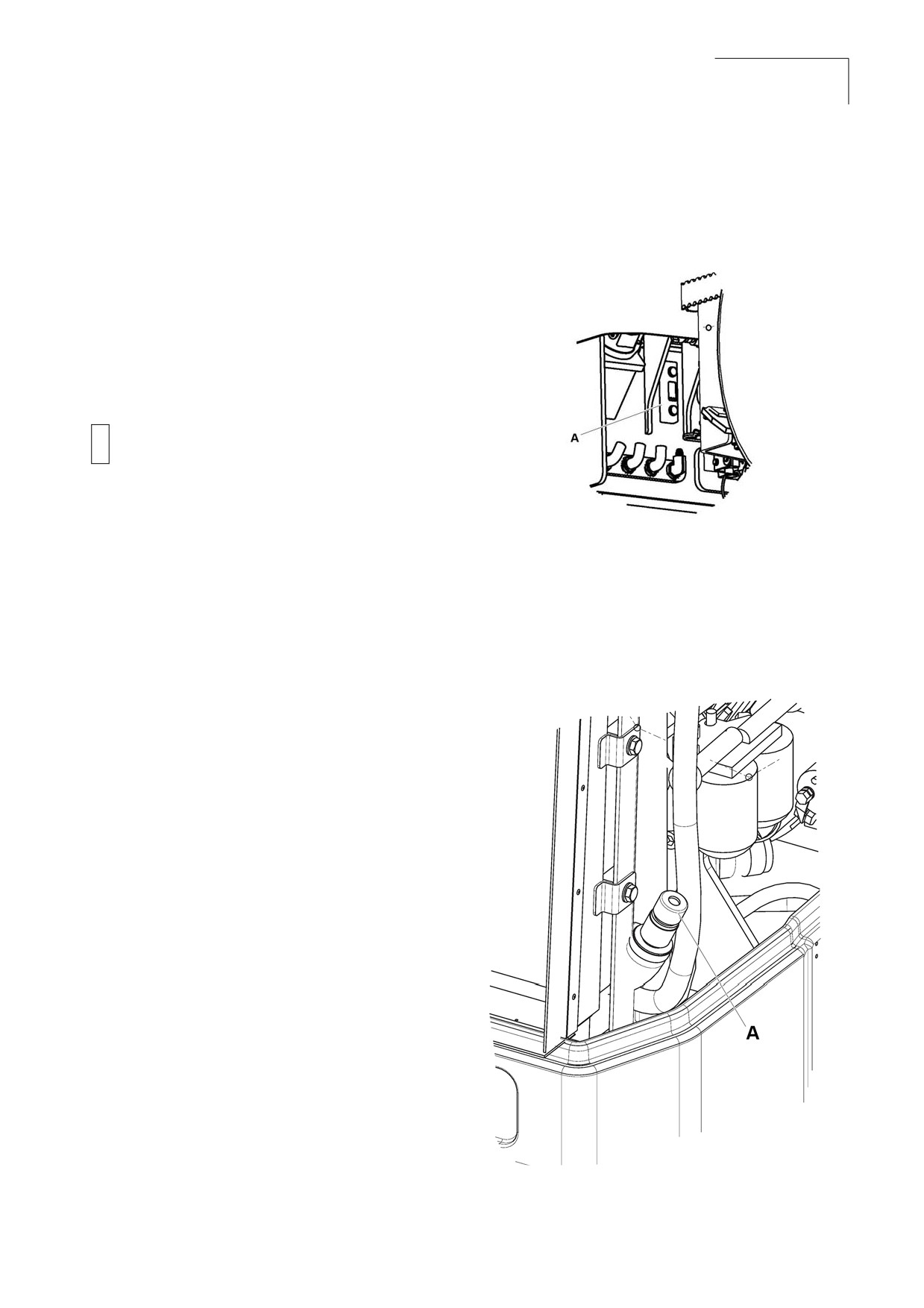
CC 125
Maintenance
65
Instruction Manual
2. Check the reservoir oil level by viewing the
7.6 Lubrication and
sight gauge. Verify that fluid level is near the
Filters
maximum level indicated on the sight glass.
Figure 7-13: Hydraulic Reservoir
Hydraulic Reservoir
The hydraulic reservoir oil level must be checked
daily as part of the 8 to 10 hour routine
maintenance procedure.
Excessive hydraulic oil can rupture
!
hydraulic tank and cause injury or
property damage.
N o t e Take extra care when working around
or on the hydraulic system to make
A
Sight glass
sure its complete cleanliness. When
operating, the oil level must be
3.
Open the engine hood and unscrew the filler
between the maximum and minimum
cap, top up with hydraulic fluid (as per
levels. Top up with hydraulic fluid as
lubricant specification) if the level is too low.
per lubricant specifications if level is
too low.
Note Dirt in the hydraulic system will lead to
Figure 7-14: Hydraulic fluid Refilling
premature component failure. A clean,
contaminant free system is extremely
important for the roller to function
properly.
Checking Hydraulic Oil Level
If the hydraulic oil level is low, add hydraulic oil.
1. Level the roller.
A Hydraulic fluid refilling
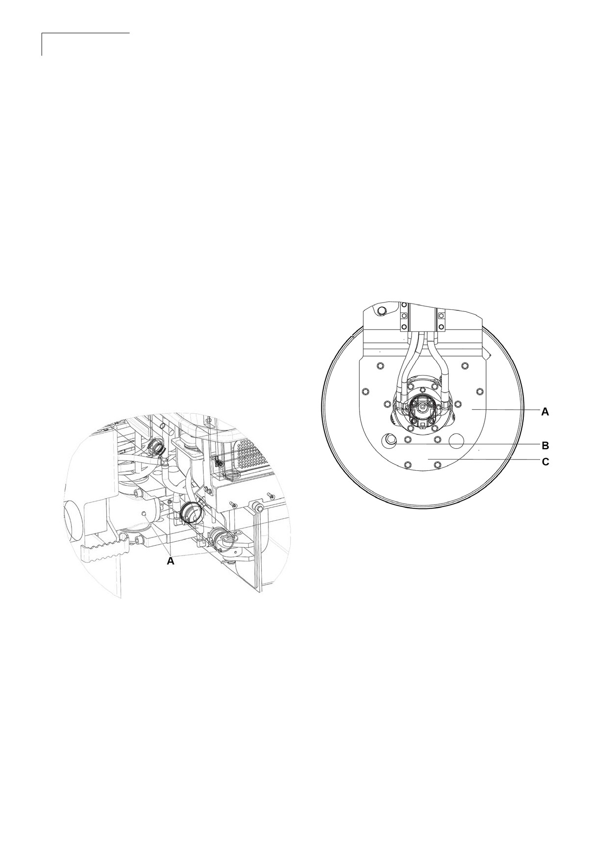
CC 125
66
Maintenance
Instruction Manual
Steering Cylinder and Steering
Drum - Oil Level
Joint
1. Run the roller slowly until the oil plug is
opposite one of the inspection holes.
The steering cylinder is located under the
operator’s platform. There is a grease fitting near
2. Unscrew the plug and check that the oil level
the base and rod ends of the cylinder.
reaches up to the bottom of the hole. Top up
with new oil if necessary. Use oil as per the
lubricant specification.
1. Turn the steering wheel fully to the left. All
four grease nipples can now be accessed
3. Clean the magnetic oil plug from any metallic
from the right side of the machine.
residue, and refit the plug.
2. Wipe the grease nipples.
3. Grease each nipple with five strokes of the
Figure 7-16: Drum Oil Filling
hand-operated grease gun. Make sure that
grease penetrates into the bearing. If grease
does not penetrate the bearings, it may be
necessary to relieve the articulation joint with
a jack while repeating the greasing process.
Figure 7-15: Greasing
A
Filling
B
Level check
C Drain
A Grease nipple
Controls
If the lever gets stiff after a prolonged period of
use, remove the cover and lever and lubricate.
Lubricate the forward/reverse lever in the engine
compartment with a few drops of oil.
CC 125
Maintenance
67
Instruction Manual
Housekeeping
The complete roller must be given a weekly
cleaning. Daily cleaning will be required if material
is adhering to the roller working parts.
1. Make sure the operator areas, steps, and
grab rails are clean. Oil, grease, snow, ice, or
mud in these areas can be slippery. Clean
the boots of excess mud before getting in the
cab or on the roller operator platform.
2. Check the tower feed installation for debris
buildup around the sheaves.
3. Thoroughly wash all fittings, caps, plugs, and
the like with a nonflammable, nontoxic
cleaning solution before servicing to prevent
dirt from entering while performing the
service.
Note Protect all electrical components and
control panels against entry of water
or steam when using high pressure
cleaning methods. Cover the fuel and
hydraulic fill cap breathers located on
each tank.
4. After cleaning, check for defects in the air
cleaner ducts.
a. Check intake for accumulation of
debris that could restrict air flow.
b. Check air cleaner mounting hardware
for security.
c. Check all hoses for cracks, chafing, or
deterioration and replace at the first
sign of probable failure.