DYNAPAC Vibratory roller CC1200 Engine Kubota D1703. Operation & Maintenance (2012)
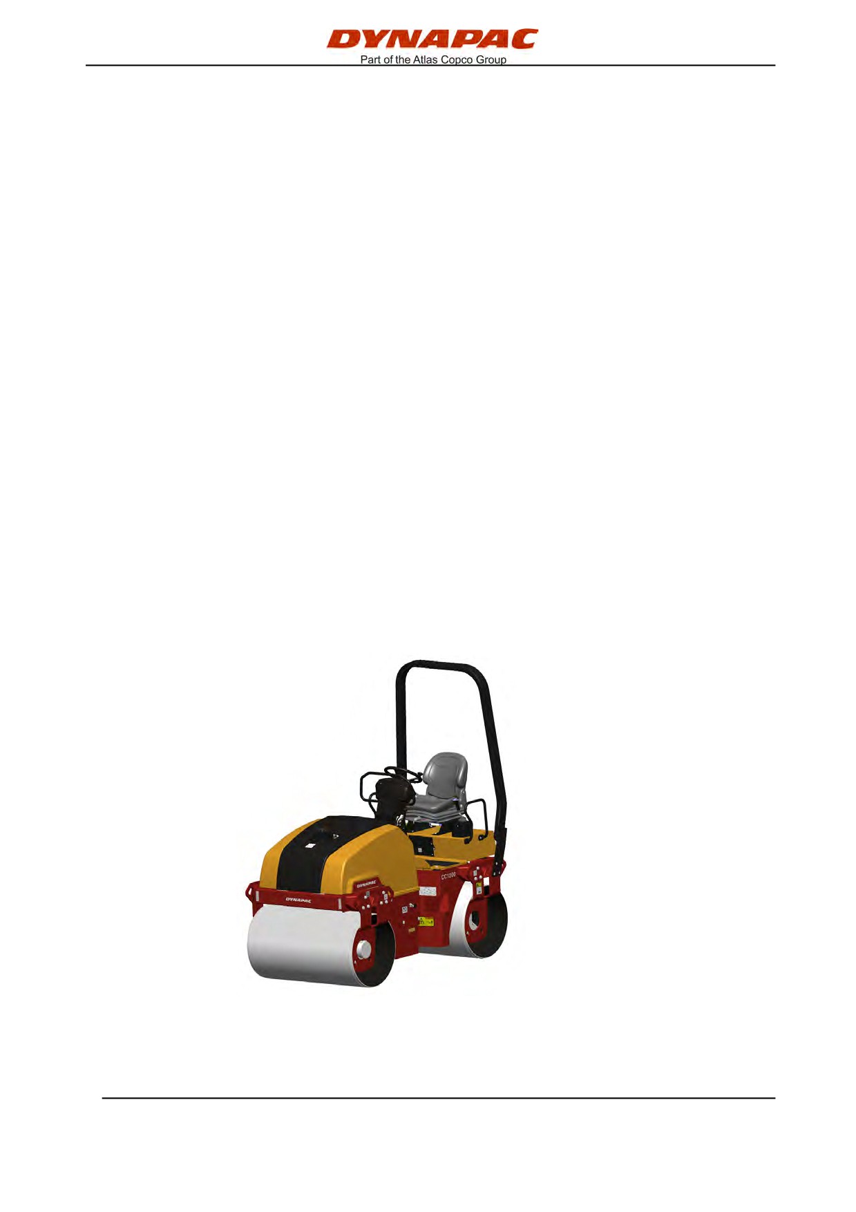
Instruction manual
Operation & Maintenance
Vibratory roller
CC1200
Engine
Kubota D1703
Serial number
10000332x0A000001 -
Translation of original instructions
Subject to changes
Printed in Sweden
Table of Contents
Introduction
1
The machine
1
Intended use
1
Warning symbols
1
Safety information
1
General
2
CE marking and Declaration of conformity
3
Safety - General instructions
5
Safety - when operating
7
Driving near edges
7
Slopes
8
Special instructions
9
Standard lubricants and other recommended oils and fluids
9
Higher ambient temperatures, above +40°C (104°F)
9
Lower ambient temperature - Freeze risk
9
Temperatures
9
High pressure cleaning
9
Fire fighting
10
Roll Over Protective Structure (ROPS)
10
Battery handling
10
Jump starting
11
Technical specifications
13
Vibrations - Operator station
13
Noise level
13
Dimensions, top view
14
Dimensions, side view
15
Weights and volumes
16
Working capacity
16
General
16
Tightening torque
17
2012-04-20
ROPS - bolts
18
Hydraulic system
18
Machine description
19
Identification
19
Product identification number on the frame
19
Explanation of 17PIN serial number
19
Machine plate
20
Engine plates
20
Location - decals
22
Safety decals
23
Info decals
24
Instruments/Controls
26
Locations - Instruments and controls
26
Locations - Control panel and controls
27
Function description
28
Electrical system
31
Fuses
31
Operation
33
Before starting
33
Master switch - Switching on
33
Driver seat (Std) - Adjustment
33
Driver seat (Option) - Adjustment
34
Instruments and lamps - Checking
34
Interlock
35
Parking brake - Check
35
Operator position
36
Starting
37
Starting the engine
37
Driving
39
Operating the roller
39
2012-04-20
Interlock/Emergency stop/Parking brake - Check
40
Vibration
40
Manual/Automatic vibration
40
Braking
41
Normal braking
41
Emergency braking
42
Switching off
42
Parking
43
Chocking the drums
43
Battery disconnector
43
Long-term parking
45
Engine
45
Battery
45
Air cleaner, exhaust pipe
45
Fuel tank
45
Hydraulic reservoir
45
Water tank
45
Steering cylinder, hinges, etc
46
Hoods, tarpaulin
46
Miscellaneous
47
Lifting
47
Locking the articulation
47
Lifting the roller
47
Unlocking the articulation
48
Towing/Recovering
49
Release the brakes
49
Releasing the brake, High torque motor
(Optional) (p/n 4700380594)
50
Towing the roller
51
Roller prepared for transport
51
2012-04-20
Retractable ROPS (Optional)
52
Operating instructions - Summary
53
Preventive maintenance
55
Acceptance and delivery inspection
55
Warranty
55
Maintenance - Lubricants and symbols
57
Maintenance symbols
58
Maintenance - Maintenance schedule
59
Service and maintenance points
59
General
60
Every 10 hours of operation (Daily)
60
After the FIRST 50 hours of operation
60
Every 50 hours of operation (Weekly)
61
Every 250 hours of operation (Monthly)
61
Every 500 hours of operation (Every three months)
61
Every 1000 hours of operation (Every six months)
62
Every 2000 hours of operation (Yearly)
62
Maintenance, 10h
63
Check - Coolant system
63
Hydraulic reservoir, Level check - Filling
64
Lowering of engine hood
65
Air circulation - Check
65
Fuel tank - Filling
66
Sprinkler system/Drum
Checking - Cleaning
66
Water tank - Filling
67
Scrapers, fixed
Checking - Setting
67
Scrapers, spring-action (Optional)
Checking - Adjustment
68
Brakes - Check
68
2012-04-20
Maintenance - 50h
71
Air cleaner indicator
71
Air cleaner
Check - Replacement of main filter
71
Air filter indicator - Resetting
72
Backup filter - Change
72
Air cleaner
- Cleaning
73
Steering cylinder and steering joint - Lubrication
73
Maintenance - 250h
75
Coolers
Checking - Cleaning
75
Battery
- Check condition
76
Engine oil and oil filter - Change
77
Maintenance - 500h
79
Drum - oil level
Inspection - filling
79
Rubber elements and attachment screws
Check
80
Hydraulic reservoir cap - Check
80
Controls - Lubrication
80
Check - Coolant system
81
Maintenance - 1000h
83
Replacing the hydraulic oil filter
83
Hydraulic fluid reservoir - Draining
85
Replacing the fuel filter
85
Replacing the pre-filter
86
Maintenance - 2000h
87
Hydraulic tank - Changing the fluid
87
Drum - Oil change
88
Water tank - Draining
88
2012-04-20
Water pump - Draining
89
Water tank - Cleaning
89
Fuel tank - Cleaning
90
Steering joint - Check
90
2012-04-20
Introduction
Introduction
The machine
Dynapac CC1200 is a self-propelled vibratory tandem
roller in the 2 metric tonnes class featuring 1200 mm
wide drums. The machine is equipped with drive,
brakes, and vibration on both drums.
Intended use
CC1200 has primarily been designed for the
compaction of asphalt, but has excellent compaction
capacity for reinforcement layers and bearing courses.
The roller is mainly intended for compacting asphalt on
streets and minor roads in towns. It has sufficient
capacity to follow a small asphalt paver.
Warning symbols
WARNING ! Marks a danger or a hazardous
procedure that can result in life threatening or
serious injury if the warning is ignored.
CAUTION ! Marks a danger or hazardous
procedure that can result in damage to the
machine or property if the warning is ignored.
Safety information
It is recommended to at least train operators in
handling and daily maintenance of the machine
in accordance with the instruction manual.
Passengers are not allowed on the machine, and
you must sit in the seat when operating the
machine.
The safety manual supplied with the machine
must be read by all roller operators. Always
follow the safety instructions. Do not remove
the manual from the machine.
We recommend that the operator reads the
safety instructions in this manual carefully.
Always follow the safety instructions. Ensure
that this manual is always easily accessible.
2012-04-20
1
Introduction
Read the entire manual before starting the
machine and before carrying out any
maintenance.
Replace immediately the instruction manuals if
lost, damaged or unreadable.
Ensure good ventilation (extraction of air by fan)
where the engine is run indoors.
CALIFORNIA
Proposition 65 Warning
Diesel engine exhaust and some of its constituents are
known to the State of California to cause cancer, birth
defects, and other reproductive harm.
General
This manual contains instructions for machine
operation and maintenance.
The machine must be correctly maintained for
maximal performance.
The machine should be kept clean so that any
leakages, loose bolts and loose connections are
discovered at as early a point in time as possible.
Do not spray with high-pressure cleaner directly onto
gaskets and bearing spacings in steering hitch and
drum.
Inspect the machine every day, before starting.
Inspect the entire machine so that any leakages or
other faults are detected.
Check the ground under the machine. Leakages are
more easily detected on the ground than on the
machine itself.
THINK ENVIRONMENT ! Do not release oil,
fuel and other environmentally hazardous
substances into the environment. Always send
used filters, drain oil and fuel remnants to
environmentally correct disposal.
This manual contains instructions for periodic
maintenance normally carried out by the operator.
2012-04-20
2
Introduction
Additional instructions for the engine can be
found in the manufactuer's engine manual.
CE marking and Declaration of conformity
(Applies to machines marketed in EU/EEC)
This machine is CE marked. This shows that on
delivery it complies with the basic health and safety
directives applicable for the machine in accordance
with machinery directive 2006/42/EC and that it also
complies with other directives applicable for this
machine.
A "Declaration of conformity" is supplied with this
machine, which specifies the applicable directives and
supplements, as well as the harmonized standards
and other regulations that are applied.
2012-04-20
3
Introduction
2012-04-20
4
Safety - General instructions
Safety - General instructions
(Also read the safety manual)
1.
The operator must be familiar with the contents of the OPERATION section
before starting the roller.
2.
Ensure that all instructions in the MAINTENANCE section are followed.
3.
Only trained and/or experienced operators are to operate the roller.
Passengers are not permitted on the roller. Remain seated at all times when
operating the roller.
4.
Never use the roller if it is in need of adjustment or repair.
5.
Only mount and dismount the roller when it is stationary. Use the intended
grips and rails. Always use the three-point grip (both feet and one hand, or
one foot and both hands) when mounting or dismounting the machine.
Never jump down from the machine.
6.
The ROPS (Roll Over Protective Structure) should always be used when the
machine is operated on unsafe ground.
7.
Drive slowly in sharp bends.
8.
Avoid driving across slopes. Drive straight up or straight down the slope.
9.
When driving close to edges, ditches or holes, make sure that at least 2/3 of
the drum width is on previously compacted material (solid surface).
10.
Make sure that there are no obstacles in the direction of travel, on the
ground, in front of or behind the roller, or overhead.
11.
Drive particularly carefully on uneven ground.
12.
Use the safety equipment provided. The seat belt must be worn on machines
fitted with ROPS/ROPS-cab.
13.
Keep the roller clean. Clean any dirt or grease that accumulates on the
operator platform immediately. Keep all signs and decals clean and legible.
14.
Safety measures before refueling:
- Stop the engine
- Do not smoke.
- No naked flames in the vicinity of the roller.
- Earth the filling equipment nozzle to the tank opening to avoid sparks.
15.
Before repairs or service:
- Chock the drums/wheels and under the strike-off blade.
- Lock the articulation if necessary
2012-04-20
5
Safety - General instructions
16. Hearing protection is recommended if the noise level exceeds 85 dB(A). The
noise level can vary depending on the equipment on the machine and the
surface the machine is being used on.
17. Do not make any changes or modifications to the roller that could affect
safety. Changes are only to be made after written approval has been given
by Dynapac.
18. Avoid using the roller before the hydraulic fluid has reached its normal
working temperature. Braking distances can be longer than normal when the
fluid is cold. See instructions in the STOP section.
19. For your own protection always wear:
- helmet
- working boots with steel toecaps
- ear protectors
- reflecting clothing/high visibility jacket
- working gloves
2012-04-20
6
Safety - when operating
Safety - when operating
Prevent persons from entering or remaining in
the danger area, i.e. a distance of at least 7 m
(23 ft) in all directions from operating machines.
The operator may allow a person to remain in
the danger area, but should then observe
caution and operate the machine only when the
person is visible or has given clear indications
of where he or she is.
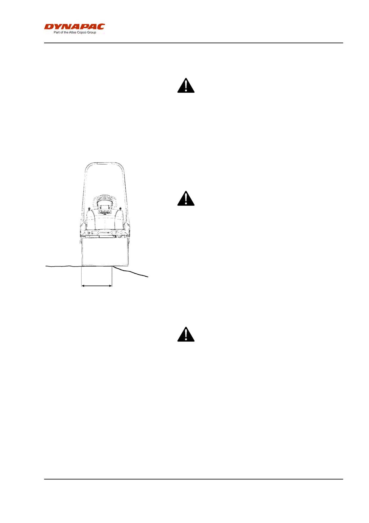
Driving near edges
When driving near an edge, minimum 2/3 of the drum
width must be on solid ground.
Keep in mind that the machine's center of
gravity moves outwards when steering. For
example, the center of gravity moves to the right
when you steer to the left.
≥ 2/3
Fig. Position of drum when driving
near an edge
Where possible, avoid driving across slopes.
Drive instead straight up and down sloping
ground.
2012-04-20
7
Safety - when operating
Slopes
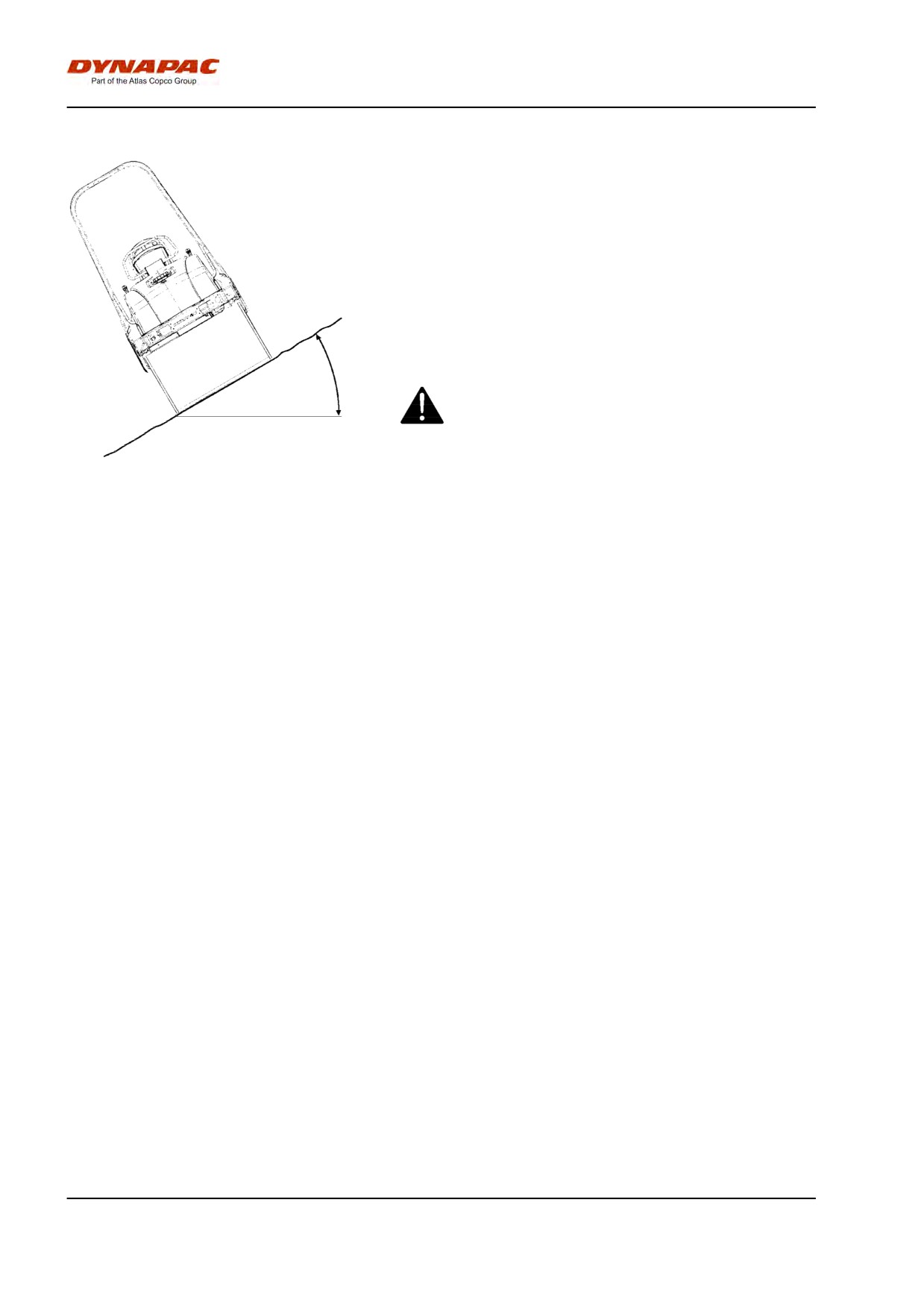
This angle has been measured on a hard, flat surface
with the machine stationary.
The steering angle was zero, the vibration was
switched OFF and all tanks were full.
Always take into consideration that loose ground,
steering the machine, vibration on, machine speed
across the ground and raising the center of gravity can
all cause the machine to topple at smaller slope
angles than those specified here.
It is recommended that ROPS (Roll Over
Max 20° or 36%
Protective Structure) or a ROPS approved cab,
is always used when driving on slopes or
unsafe ground.
Fig. Operating on slopes
2012-04-20
8
Special instructions
Special instructions
Standard lubricants and other recommended
oils and fluids
Before leaving the factory, the systems and
components are filled with the oils and fluids specified
in the lubricant specification. These are suitable for
ambient temperatures in the range -15°C to +40°C
(5°F - 105°F).
The maximum temperature for biological
hydraulic fluid is +35°C (95°F).
Higher ambient temperatures, above +40°C
(104°F)
For operation of the machine at higher ambient
temperatures, however maximum +50°C (122°F), the
following recommendations apply:
The diesel engine can be run at this temperature using
normal oil. However, the following fluids must be used
for other components:
Hydraulic system - mineral oil Shell Tellus T100 or
similar.
Lower ambient temperature - Freeze risk
Make sure that the watering system is empty/drained
of water (sprinkler, hoses, tank/s) or that anti-freeze
has been added, to prevent the system freezing.
Temperatures
The temperature limits apply to standard versions of
rollers.
Rollers equipped with additional equipment, such as
noise suppression, may need to be more carefully
monitored in the higher temperature ranges.
High pressure cleaning
Do not spray water directly onto electrical components
or the instrument panels.
Place a plastic bag over the fuel filler cap and secure
with a rubber band. This is to avoid high pressure
water entering the vent hole in the filler cap. This could
cause malfunctions, such as the blocking of filters.
Do not spray with high-pressure cleaner directly onto
gaskets and bearing spacings in steering hitch and
drum.
2012-04-20
9
Special instructions
Never aim the water jet directly at the fuel tank
cap. This is particularly important when using a
high-pressure cleaner.
Fire fighting
If the machine catches fire, use an ABC-class powder
fire extinguisher.
A BE-class carbon dioxide fire extinguisher can also
be used.
Roll Over Protective Structure (ROPS)
If the machine is fitted with a Roll Over
Protective Structure (ROPS) never carry out any
welding or drilling in the structure or cab.
Never attempt to repair a damaged ROPS
structure or cab. These must be replaced with
new ROPS structure or cabs.
Battery handling
When removing batteries, always disconnect the
negative cable first.
When fitting batteries, always connect the
positive cable first.
Dispose of old batteries in an environmentally
friendly way. Batteries contain toxic lead.
Do not use a quick-charger for charging the
battery. This may shorten battery life.
2012-04-20
10
Special instructions
Jump starting
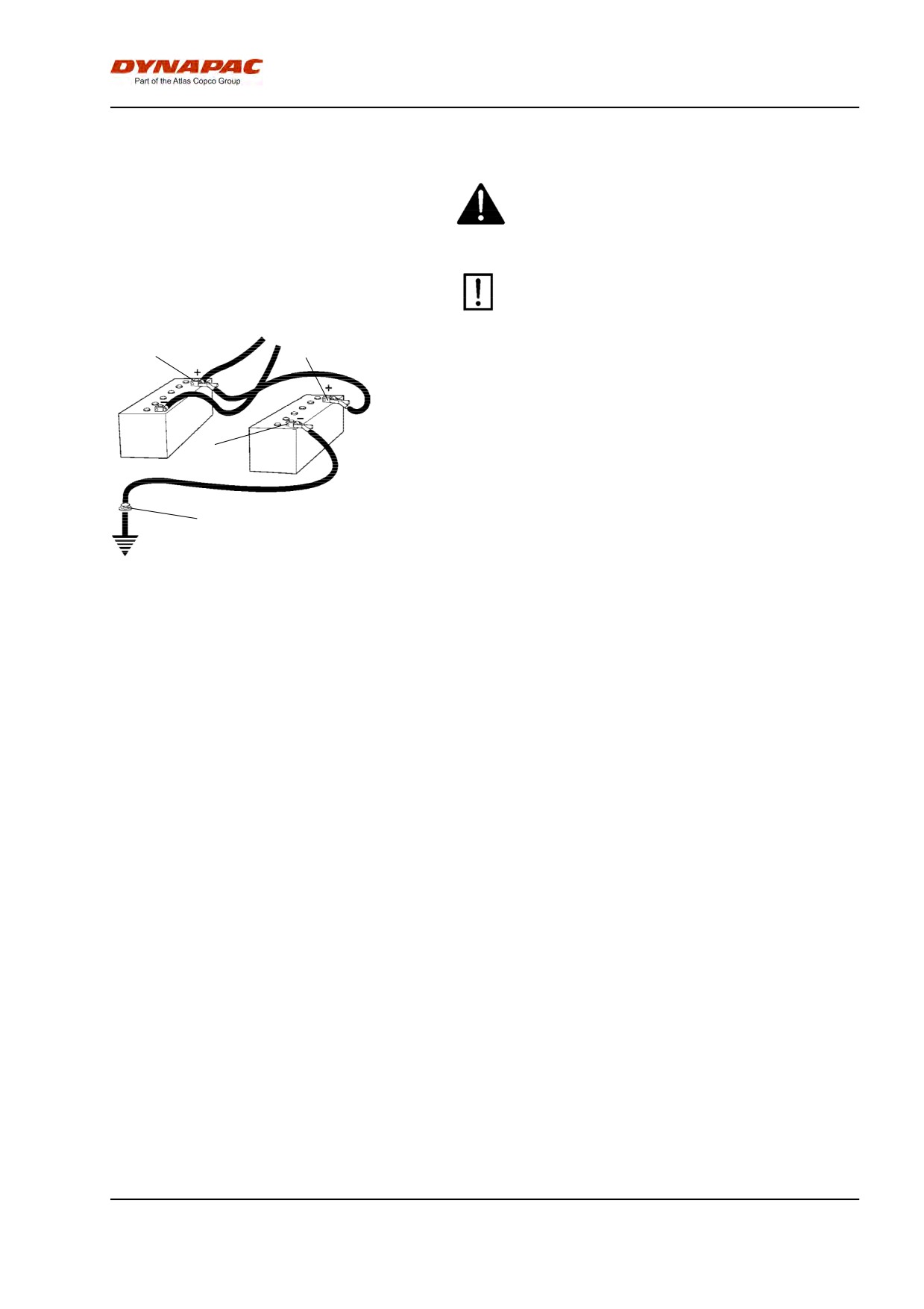
Do not connect the negative cable to the
negative terminal on the dead battery. A spark
can ignite the oxy-hydrogen gas formed
around the battery.
Check that the battery used for jump starting
has the same voltage as the dead battery.
1
2
Turn the ignition and all power consuming equipment
off. Switch off the engine on the machine which is
providing jump start power.
First connect the jump start battery's positive terminal
(1) to the flat battery's positive terminal (2).Then
3
connect the jump start battery's negative terminal (3)
to, for example, a bolt (4) or the lifting eye on the
machine with the flat battery.
4
Start the engine on the power providing machine. Let it
run for a while. Now try to start the other machine.
Disconnect the cables in the reverse order.
Fig. Jump starting
2012-04-20
11
Special instructions
2012-04-20
12
Technical specifications
Technical specifications
Vibrations - Operator station
(ISO 2631)
The vibration levels are measured in accordance with the operational cycle described in
EU directive 2007/14/EC on machines equipped for the EU market, with vibration switched
on, on soft polymer material and with the operator’s seat in the transport position.
Measured whole-body vibrations are below the action value of 0.5 m/s² as specified in Directive
2002/44/EC. (Limit is 1.15 m/s²)
Measured hand/arm vibrations also were below the action level of 2.5 m/s² specified in the same
directive. (Limit is 5 m/s²)
Noise level
The noise level is measured in accordance with the operational cycle described
in EU directive 2007/14/EC on machines equipped for the EU market, with the
vibration switched on, on soft polymer material and with the operator's seat in
the transport position.
Guaranteed sound power level, LwA
104
dB (A)
Sound pressure level at the operator's ear (platform), LpA
85 ±3
dB (A)
During operation the above values may differ because of the actual operational
conditions.
2012-04-20
13
Technical specifications
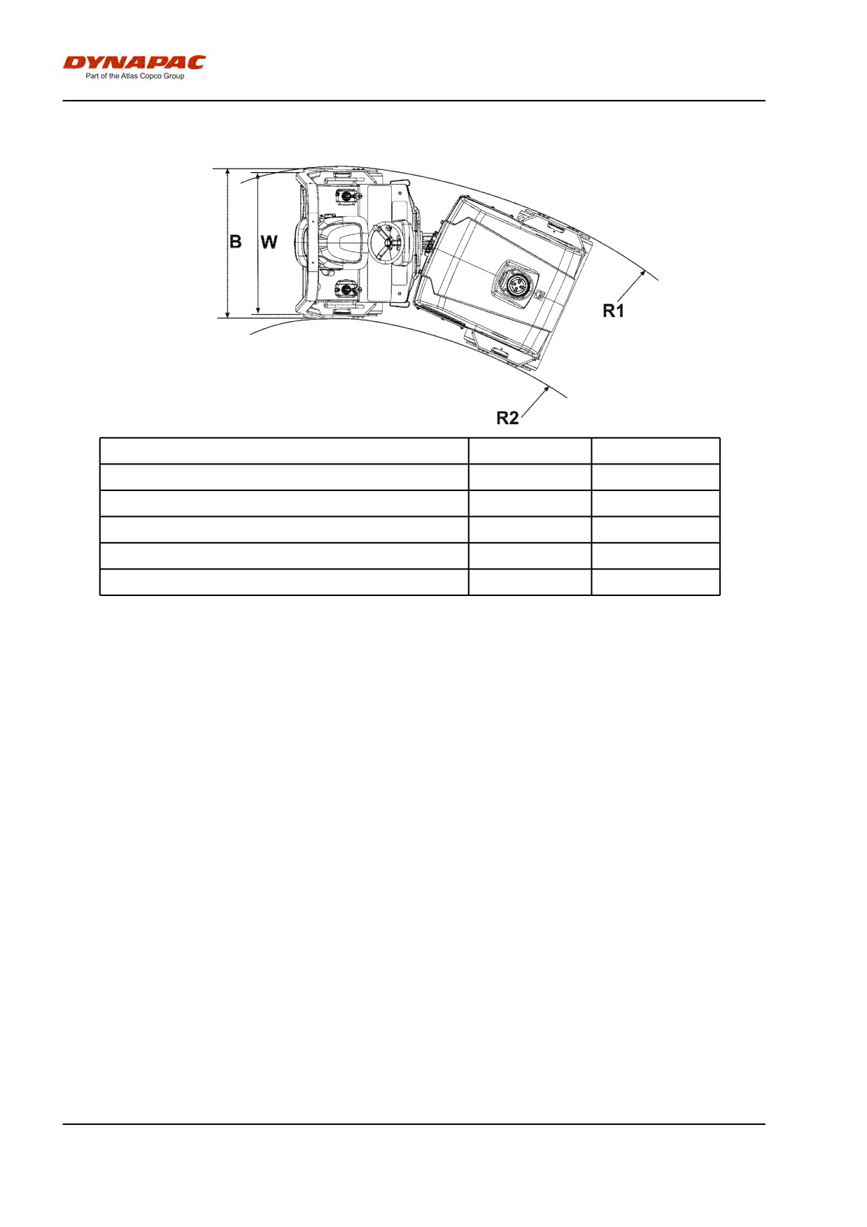
Dimensions, top view
Dimensions
mm
in
B
1310
52
B (without ROPS)
1280
50
R1
3800
150
R2
2600
102
W
1200
47
2012-04-20
14
Technical specifications
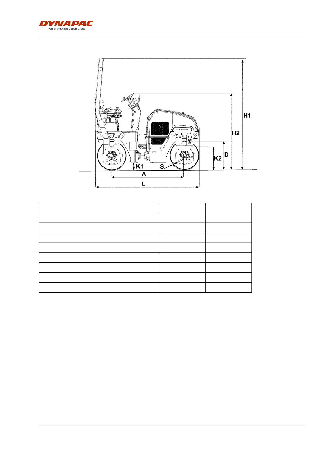
Dimensions, side view
Dimensions
mm
in
A
1715
68
D
682
27
H1
2640
104
H2
1810
71
K1
175
7
K2
550
22
L
2395
94
S
13
0.5
2012-04-20
15
Technical specifications
Weights and volumes
Weights
Weight CECE, Standard
2450 kg
5,400 lbs
equipped roller
Fluid volumes
Fuel tank
50 liters
52.9 qts
Water tank
200 liters
211.4 qts
Working capacity
Compaction data
Static linear load
10,5 kg/cm
58.8 pli
Amplitude
0,5 mm
0.019 in
Vibration frequency
58 Hz
3,480 vpm
Centrifugal force
27 kN
6,075 lb
Note: The frequency is measured at high revs. The
amplitude is measured as the real value and not
the nominal.
Propulsion
Speed range
0-10
km/h
0-6.2
mph
Climbing capacity (theoretical)
45
%
General
Engine
Manufacturer/Model
Kubota D1703
Power (SAE J1995)
26.1 kW
35 hp
Engine speed
2800*/2400 rpm
*) in US only.
Electrical system
Battery
12V 74Ah
Alternator
12V 60A
Fuses
See the Electrical system
section - fuses
2012-04-20
16
Technical specifications
Tightening torque
Tightening torque in Nm (lbf.ft) for oiled or dry bolts
tightened with a torque wrench.
Metric coarse screw thread, bright galvanized (fzb):
STRENGTH CLASS:
M -
8.8, Oiled
8.8, Dry
10.9, Oiled
10.9, Dry
12.9, Oiled
12.9, Dry
thread
M6
8,4
9,4
12
13,4
14,6
16,3
M8
21
23
28
32
34
38
M10
40
45
56
62
68
76
M12
70
78
98
110
117
131
M14
110
123
156
174
187
208
M16
169
190
240
270
290
320
M20
330
370
470
520
560
620
M22
446
497
626
699
752
839
M24
570
640
800
900
960
1080
M30
1130
1260
1580
1770
1900
2100
Metric coarse thread, zinc-treated
(Dacromet/GEOMET):
STRENGTH CLASS:
M - thread
10.9, Oiled
10.9, Dry
12.9, Oiled
12.9, Dry
M6
12,0
15,0
14,6
18,3
M8
28
36
34
43
M10
56
70
68
86
M12
98
124
117
147
M14
156
196
187
234
M16
240
304
290
360
M20
470
585
560
698
M22
626
786
752
944
M24
800
1010
960
1215
M30
1580
1990
1900
2360
2012-04-20
17
Technical specifications
ROPS-bolts which are to be torque tightened
must be dry.
ROPS - bolts
Bolt dimensions :
M16 (PN 902889)
Strength class :
10.9
Tightening torque :
192 Nm, torque class 2
(Dacromet treated)
Hydraulic system
Opening pressure
MPa
Drive system
35,0
Supply system
2,5
Vibration system
20,0
Control systems
17,0
Brake release
1,5
2012-04-20
18
Machine description
Machine description
Identification
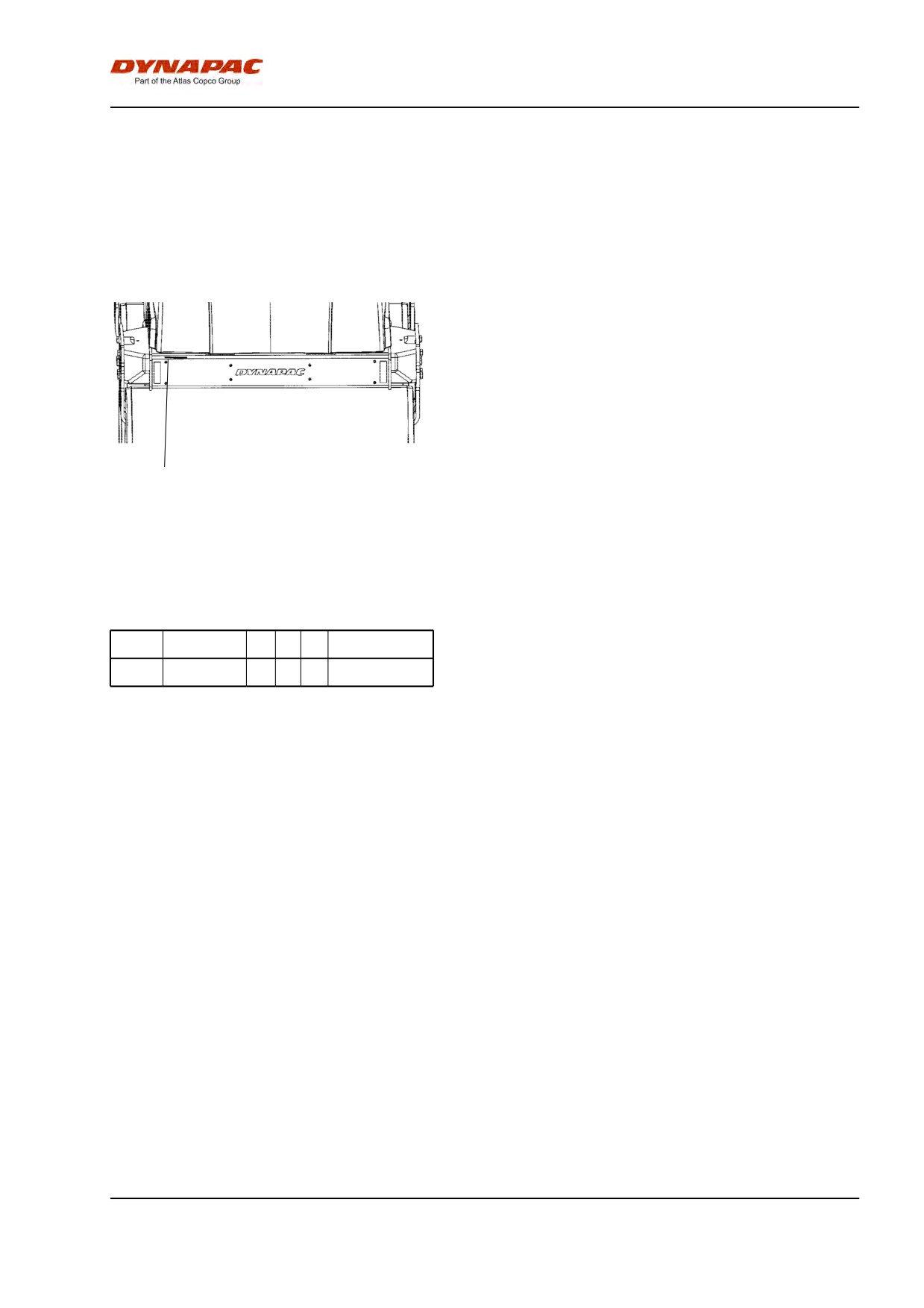
Product identification number on the frame
The machine PIN (product identification number) (1) is
punched on the right edge of the front frame.
1
Fig. PIN Front frame
1. Serial number
Explanation of 17PIN serial number
100
00123
V
0
A
123456
A= Manufacturer
A
B
C
D
E
F
B= Family/Model
C= Check letter
D= No coding
E= Production unit
F= Serial number
2012-04-20
19
Machine description
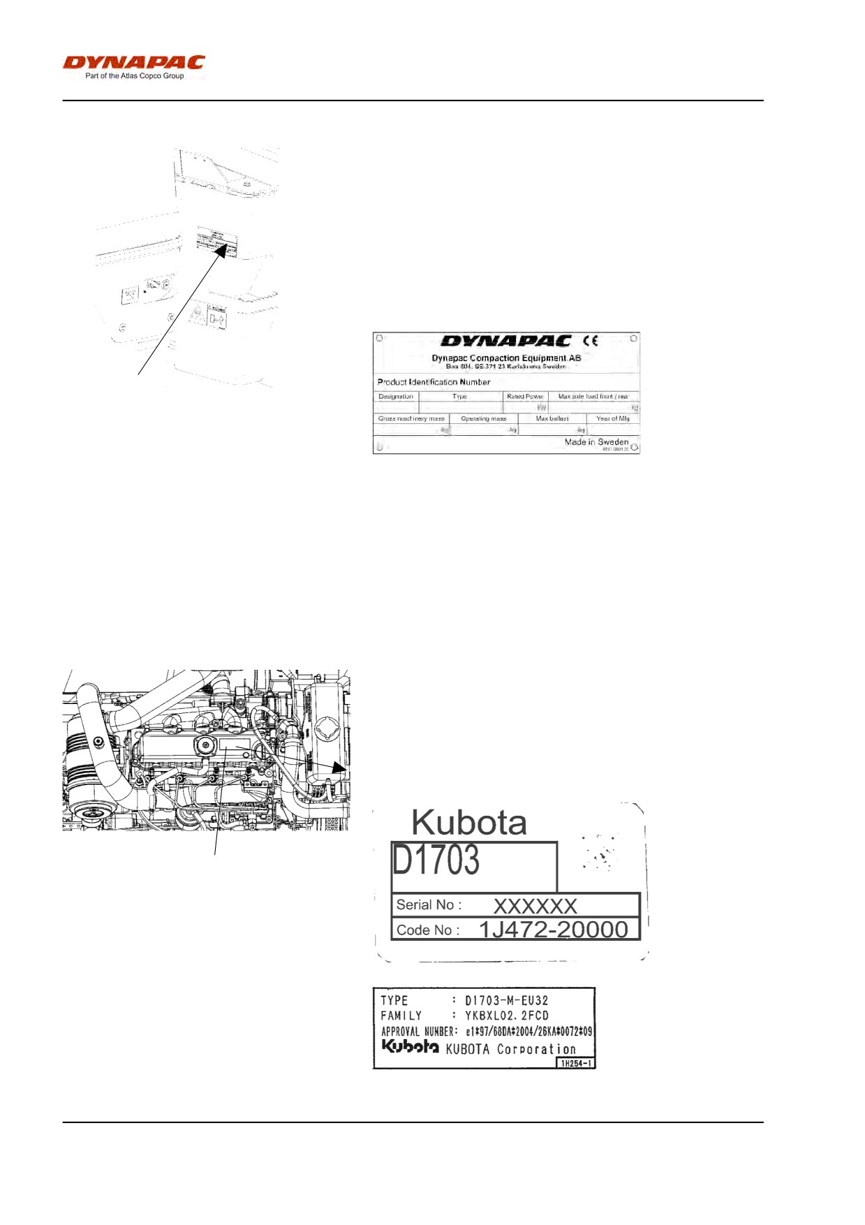
Machine plate
The machine type plate (1) is affixed on the left front
edge of the operator's platform.
The plate specifies the manufacturer's name and
address, the type of machine, the PIN number (serial
number), service weight, engine power and year of
manufacture. If the machine is delivered outside of the
EU, the plate may not have a CE marking and the year
of manufacture.
1
Fig. Operator platform
1. Machine plate
Please state the machine's PIN (serial number)
when ordering parts.
Engine plates
The engine's type plate (1) is located on top of the
cylinder head cover.
The plate specifies the type of engine, its serial
number and the engine specification.
Please specify the engine serial number when
ordering spares. Refer also to the engine manual.
1
Fig. Engine
1. Type plate
2012-04-20
20

Machine description
2012-04-20
21
Machine description
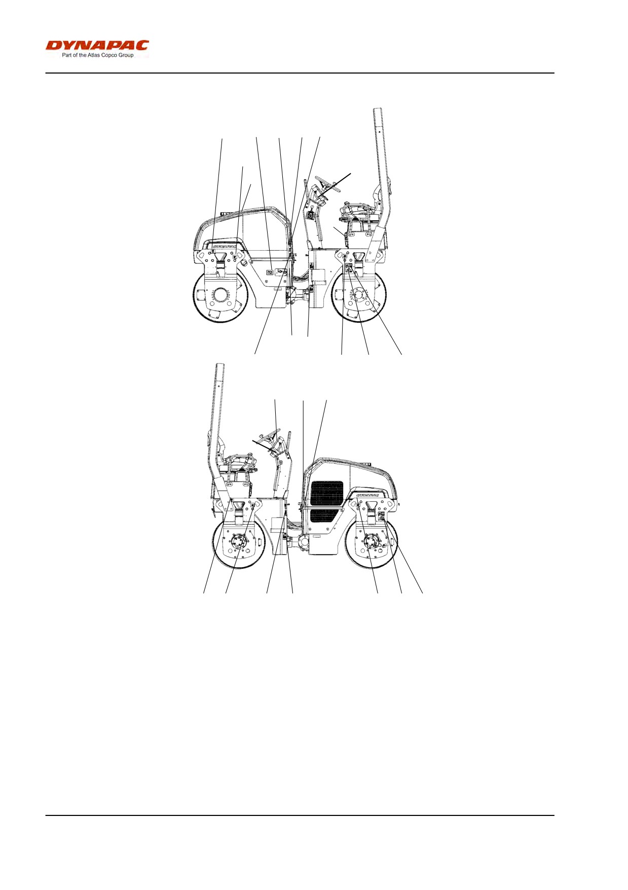
Location - decals
8
11
13
5
2
12
16
15
10
14
1
9
6
12
3
4
5
2
16
8
12
7
1
12
6
3
Fig. Location, decals and signs
1.
Warning, Crush zone
4700903422
8.
Lifting point
4700357587
2.
Warning, Rotating engine
4700903423
9.
Hydraulic fluid
4700272372
components
3.
Warning, Locking
4700908229
10.
Manual compartment
4700903425
4.
Warning, Instruction manual
4700903459
11.
Battery disconnector
4700904835
5.
Warning, Hot surfaces
4700903424
12.
Fixing point
4700382751
6.
Lifting plate
4700904870
13.
Sound power level
4700791292
7.
Diesel fuel
4700991658
14.
Hydraulic fluid level
4700272373
15.
Warning, Starting gas
4700791642
16.
Starting instructions
4812115918
2012-04-20
22
Machine description
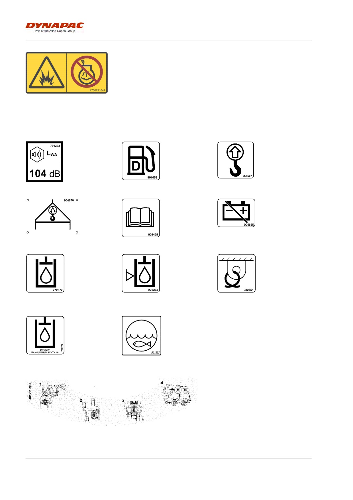
Safety decals
Always make sure that all safety decals are completely
legible, and remove dirt or order new decals if they
have become illegible. Use the part number specified
on each decal.
4700903422
Warning - Crush zone, articulation/drum.
Maintain a safe distance from the crush zone.
(Two crush zones on machines fitted with pivotal steering)
4700903423
Warning - Rotating engine components.
Keep your hands at a safe distance from the
danger zone.
4700903424
Warning - Hot surfaces in the engine compartment.
Keep your hands at a safe distance from the
danger zone.
4700903459
Warning - Instruction manual
The operator must read the safety, operation and
maintenance instructions before operating the
machine.
4700908229
Warning - Risk of crushing
The articulation must be locked when lifting.
Read the instruction manual.
2012-04-20
23
Machine description
4700791642
Warning - Starting gas
Starting gas is not to be used.
Info decals
Noise power level
Diesel fuel
Lifting point
Hoisting plate
Handbook compartment
Master switch
Hydraulic fluid
Hydraulic fluid level
Securing point
Biological hydraulic fluid,
Water
PANOLIN
Starting instructions
2012-04-20
24
Machine description
2012-04-20
25
Machine description
Instruments/Controls
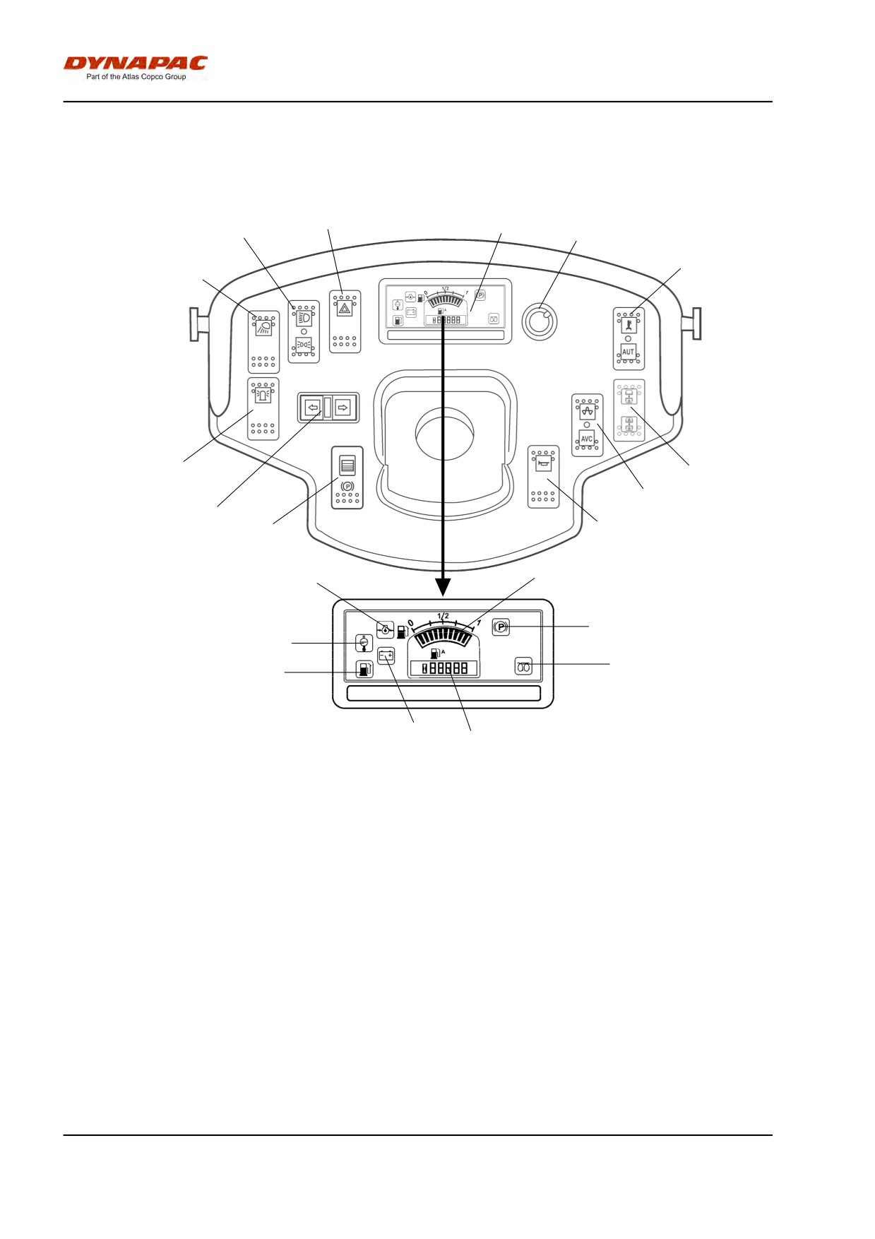
Locations - Instruments and controls
16
22
14
13
12
15
17
21
20
18
31
19
24
26
25
27
29
23
Fig. Instruments and control panel
28
30
12.
Manual/automatic sprinkler
23.
Low fuel level
13.
Sprinkler timer
24.
Oil pressure, engine
14.
Driving lights
25.
Parking brake lamp
15.
Working lights
26.
Fuel level
16.
Hazard warning lights
27.
Water temperature, engine
17.
Hazard beacon
28.
Battery/charging
18.
Direction indicators
29.
Glow plug
19.
Horn
30.
Hourmeter
20.
Vibration manual/automatic
31.
Parking brake On/Off
21.
Vibration selector Front/rear drum
22.
Control panel
*
= Option
2012-04-20
26
Machine description
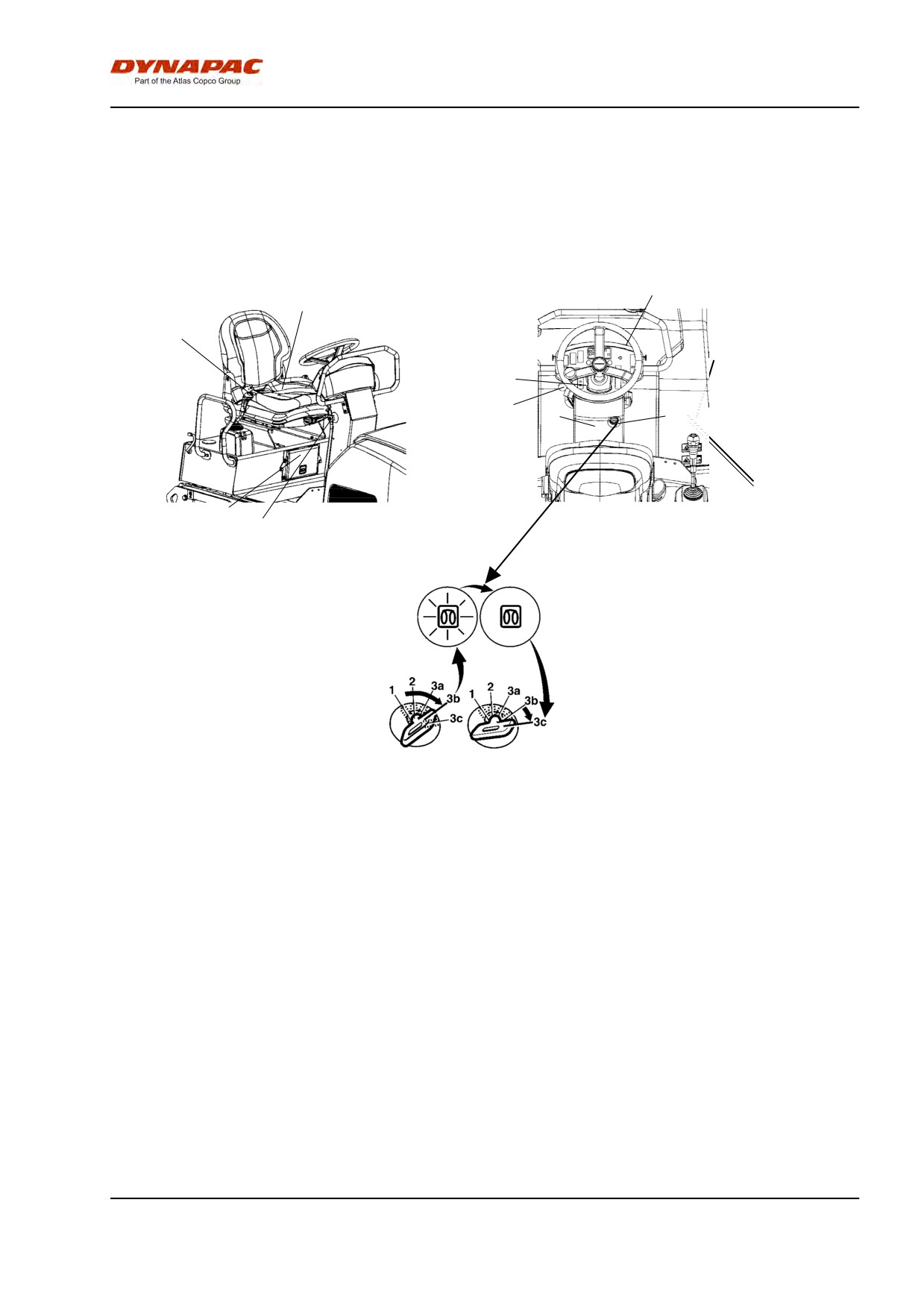
Locations - Control panel and controls
9
7
4 6
31
2
8
1
5
3
Fig. Operator position
Fig. Operator's
station
1
Starter switch
2
Throttle control
3
Emergency stop
4
Vibration On/Off
5
Handbook compartment
6
Forward/reverse lever
7
Seat switch
8
Fuse box
9
Instrument cover
2012-04-20
27
Machine description
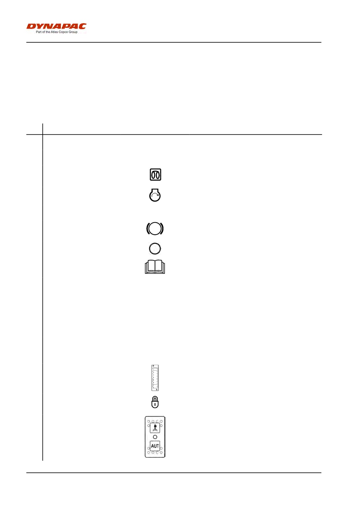
Function description
No
Designation
Symbol
Function
1.
Starter switch
Positions 1-2: Shut off position, key can be
removed.
Position 3a: All instruments and electric controls
are supplied with power.
Position 3b: Glowing. Hold the starter switch in this
position until the lamp goes out. The starter motor
is activated in the next position.
Position 3c: Starter motor activation.
2.
Throttle control
In forward position, the engine idles.
In backward position, the engine runs at full speed.
3.
Emergency stop
When pressed, the emergency stop is activated.
The engine switches off and the brakes are
activated. Brace yourself for a sudden stop.
4.
Vibration On/Off. Switch
Press once and release to switch vibration on.
Press again to switch the vibration off.
5.
Handbook compartment
Pull up and open the top of the compartment for
access to handbooks.
6.
Forward/Reverse lever
The engine can only be started when the lever is in
neutral. The engine will not start if the
forward/reverse lever is not in the neutral position.
Direction of travel and speed of the roller is
regulated with the forward/reverse lever. Move the
lever forward to drive the roller forwards, etc.
The speed of the roller is proportional to the
distance of the lever from the neutral position. The
further the lever is from the neutral position, the
higher the speed.
7.
Seat switch
Remain seated at all times when operating the
roller. If the operator stands up during operation, a
buzzer sounds. After 4 seconds the brakes are
activated and the engine stops.
8.
Fuse box (on control column)
Contains fuses for the electrical system. See under
the heading ‘Electrical system’ for a description of
fuse functions.
9.
Instrument cover
Lowered over the instrument plate to protect the
instruments from the weather and sabotage.
Lockable
12.
Sprinkler, switch (Option)
Upper position = switching on of flow of water to
drum.
Intermediate position = Sprinkling switched off
Lower position = switching on of water to drum via
forward/reverse lever. The flow of water can be
controlled by means of the sprinkler timer (13).
2012-04-20
28
Machine description
No
Designation
Symbol
Function
13.
Sprinkler timer (Optional)
Variable adjustment of water flow from 0-100%.
Only works when AUTO (12) is pressed in.
14.
Driving lights, switch
Upper position = Traffic lighting goes on
(Optional)
Intermediate position = Lighting switched off
Lower position = Parking light goes on
15.
Working lights, switch
When depressed, the working lights are on
(Optional)
16.
Hazard warning lights,
Where depressed, the hazard warning lights are on
switch (Optional)
17.
Hazard beacon, switch
Where depressed, the hazard beacon is on
18.
Direction indicators, switch
When depressed to the left, the left direction
(Optional)
indicators are on etc. In the middle position the
function is shut off.
19.
Horn, switch
Press to sound the horn.
20.
Vibration MAN/AUTO, switch
In the upper position, the vibration is switched
on/off with the switch on the forward/reverse lever.
The function is activated with the switch.
In the intermediate position the vibration system is
completely switched off.
In the lower position the vibration is switched on or
off automatically via the forward/reverse lever.
21.
Vibration selector, switch
Upper position = Vibration switch off on front drum
Lower position = Vibration on both drums.
22.
Control panel
23.
Warning lamp, low fuel level
The lamp comes on when the fuel level in the tank
is low.
2012-04-20
29
Machine description
No
Designation
Symbol
Function
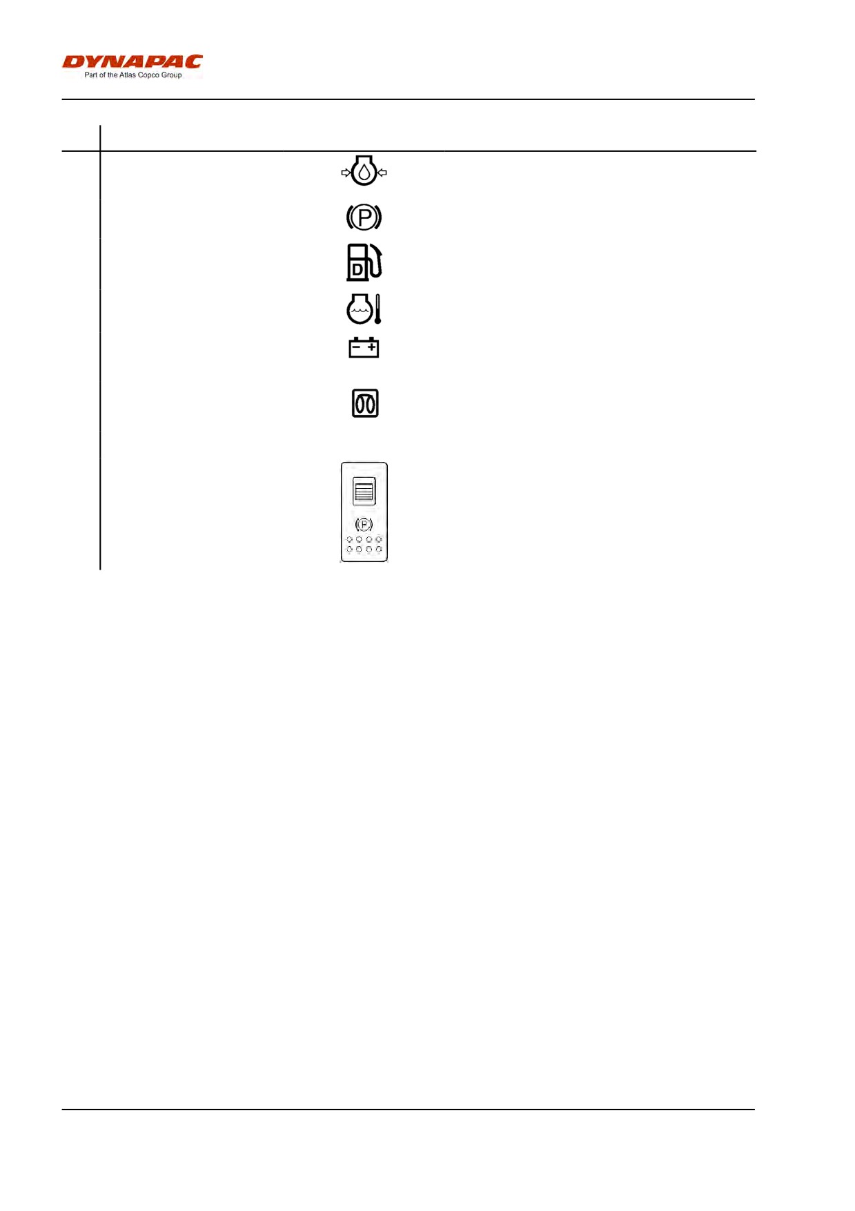
24.
Warning lamp, oil pressure
This lamp lights if the lubricating pressure in the
engine is too low. Stop the engine immediately and
locate the fault.
25.
Warning lamp, parking brake
The lamp lights when the parking brake is
activated.
26.
Fuel level
Shows the fuel level in the diesel tank.
27.
Warning lamp, water
The light comes on if the water temperature is too
temperature
high.
28.
Warning lamp, battery
If the lamp lights while the engine is running the
charging
alternator is not charging. Stop the engine and
locate the fault.
29.
Warning lamp, glow plug
The lamp must go out before the starter switch is
moved to position 3c for activation of the starter
motor.
30.
Hourmeter
Shows the number of hours the engine has run.
31.
Parking brake On/Off, switch
Push in to activate the parking brake, the machine
stops with the engine running. Always use the
parking brake when the machine is stationary
on a sloping surface.
2012-04-20
30
Machine description
Electrical system
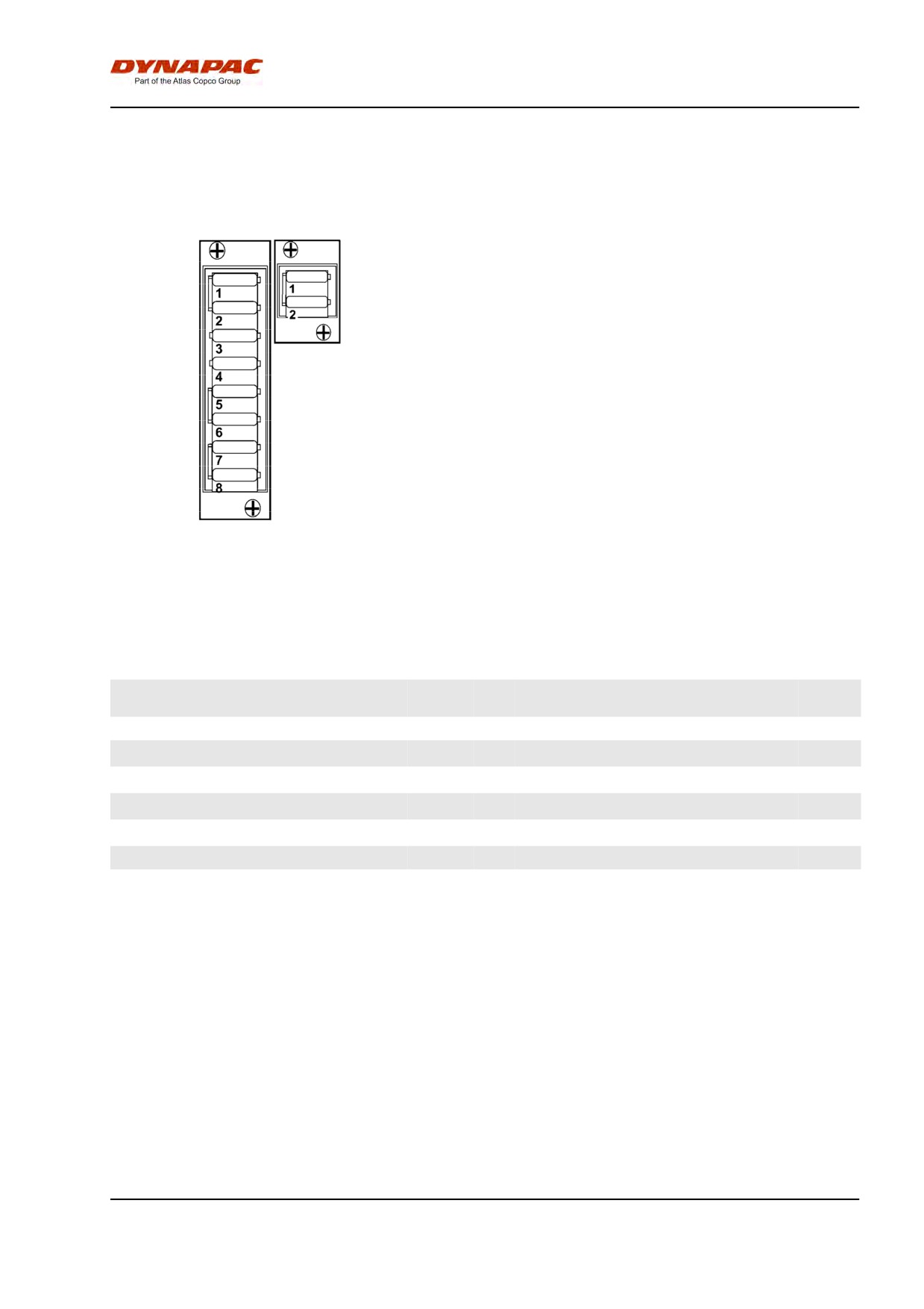
Fuses
The figure shows the position of the fuses.
The table below gives fuse amperage and function. All
2
fuses are flat pin fuses.
1
Fig. Fuse boxes
1. Upper
2. Lower
Fuse box, Upper
Fuse box, Lower
1. ECU, Interlock, Instrument panel,
10A
1.
Reserve
Sprinkler front, Vibration
2. Alternator, Horn, Fuel pump
10A
2.
Flow divider
10A
3. Indicators left
5A
4. Indicators right
5A
5. Hazard beacon
10A
6. Indicator relay, Power socket 12V
10A
7. Position lights, Working lights front
15A
8. Traffic lights, Working lights rear
15A
2012-04-20
31
Machine description
2012-04-20
32
Operation
Operation
Before starting
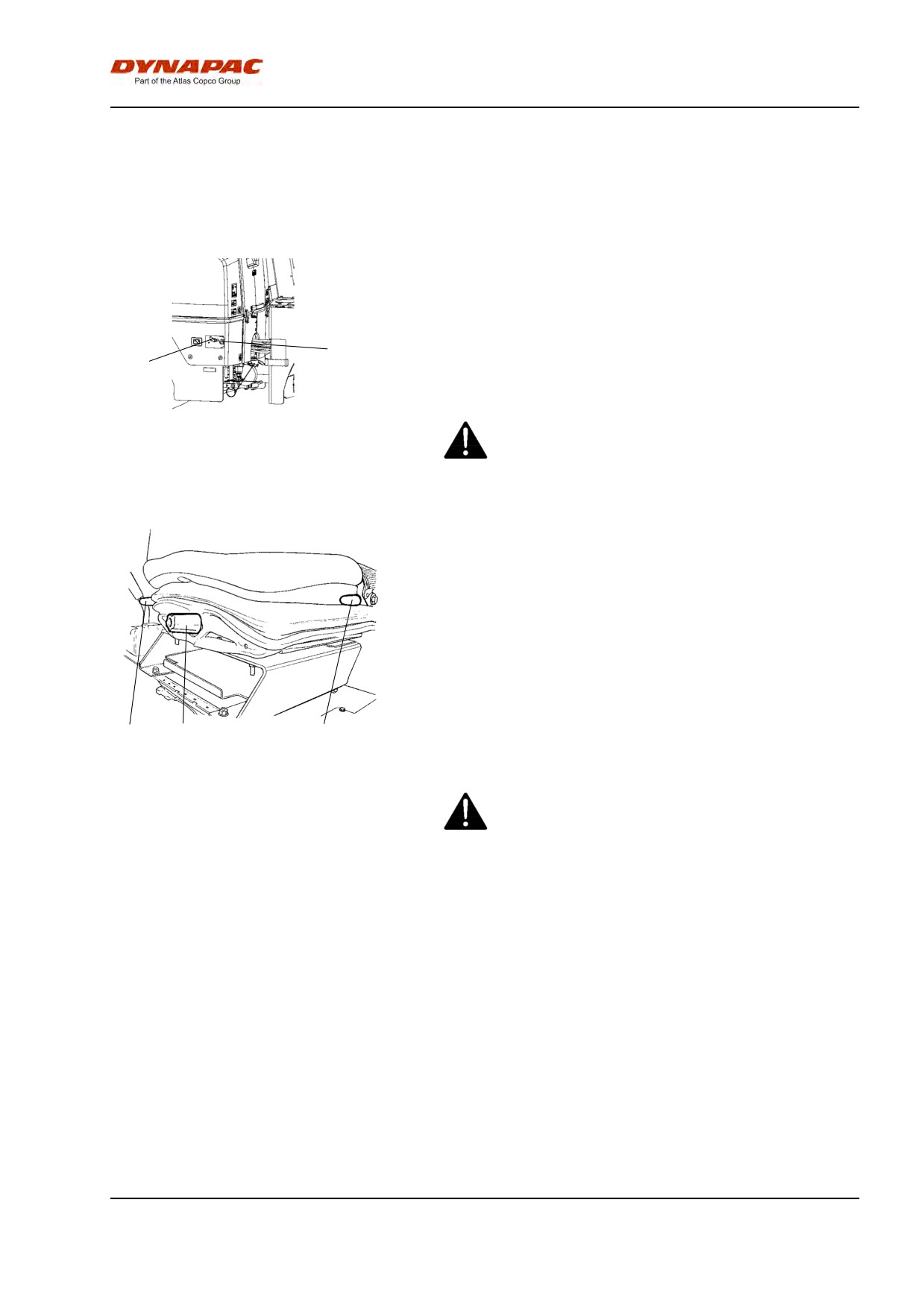
Master switch - Switching on
Remember to carry out daily maintenance. See the
maintenance instructions.
The battery disconnector is on the left side in the
engine compartment.
2
Turn the key (1) to switched on position. The roller is
1
now supplied with power.
Fig. Engine compartment
The engine hood must be unlocked during
1. Battery disconnector
2. Power socket, 12 V
operation, unless the battery disconnector is freely
accessible from the outside, so that the battery
voltage can be quickly disconnected if necessary.
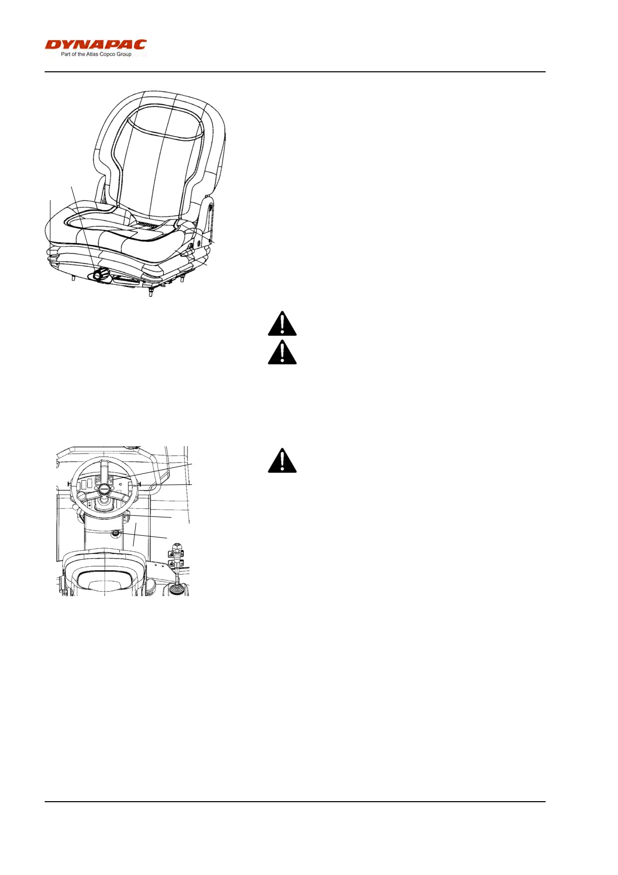
Driver seat (Std) - Adjustment
Adjust the operator’s seat so that the position is
comfortable and so that the controls are within easy
reach.
The seat can be adjusted as follows.
- Length adjustment (1)
- Backrest adjustment (2)
1
3
2
- Weight adjustment (3)
Fig. Driver seat
1. Handle - Length adjustment
2. Handle - Backrest angle
Always check that the seat is in locked position
3. Handle - Weight adjustment
before starting.
2012-04-20
33
Operation
Driver seat (Option) - Adjustment
Adjust the operator’s seat so that the position is
comfortable and so that the controls are within easy
reach.
2
1
The seat can be adjusted as follows.
- Length adjustment (1)
4
- Weight adjustment (2)
3
- Back support angle (3)
Fig. Driver seat
1. Lock lever - Length adjustment
Always make sure that the seat is secure before
2. Weight adjustment
beginning operation.
3. Back support angle
4. Seat belt
Do not forget to use the seat belt (4).
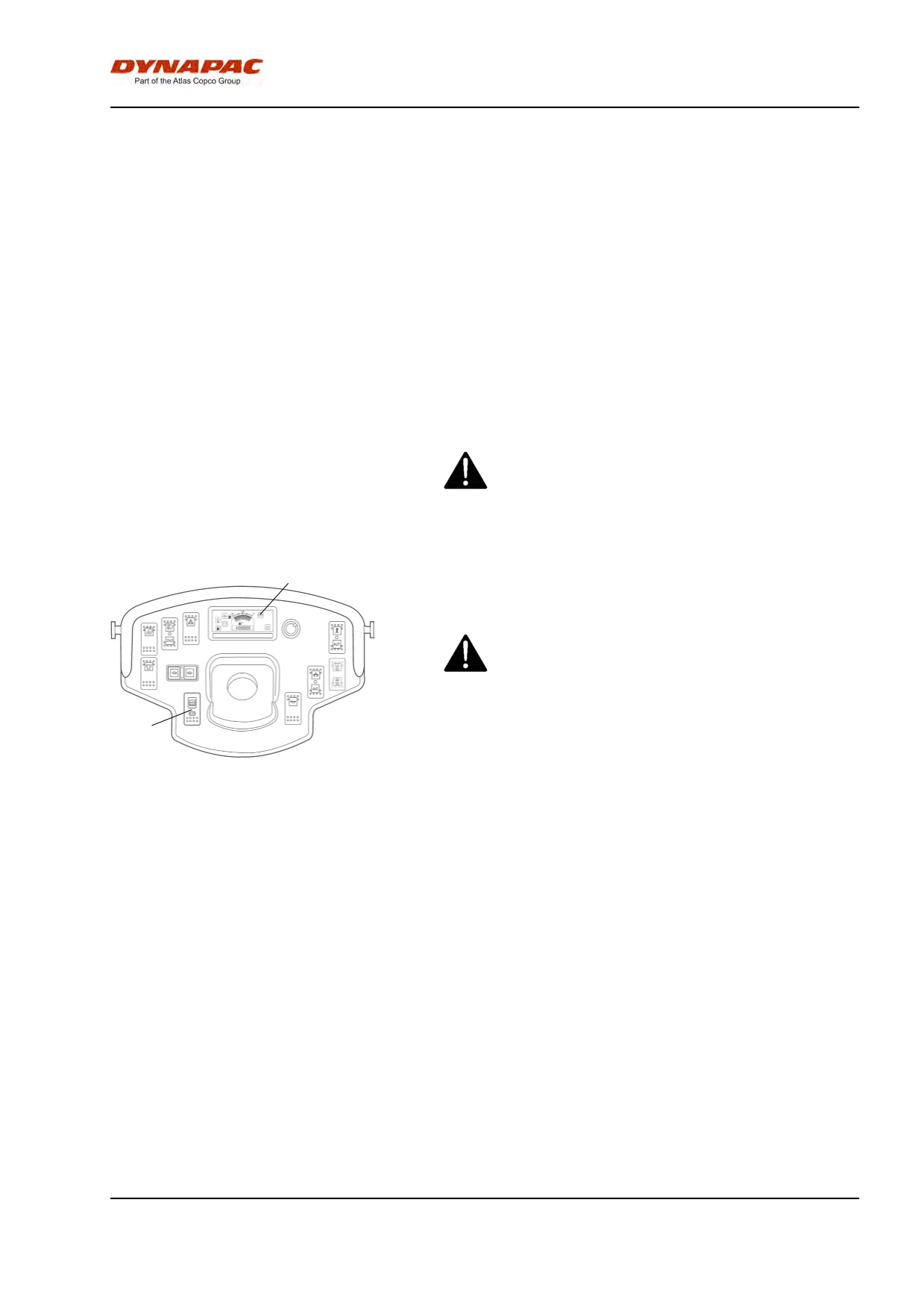
Instruments and lamps - Checking
Make sure that the emegency stop button is pulled
22
out and the parking brake is activated. When the
forward/reverse lever is in neutral, the automatic
12
brake function is engaged.
3
1
Turn the switch (1) to position 3a.
Check that the warning lamps in the warning panel
(22) come on.
Figure. Instrument panel
1. Starter switch
Set the sprinkler switch (12) to the operating position
3. Emergency stop
and check that the system is functioning.
12. Switch, watering
22. Warning panel
2012-04-20
34
Operation
Interlock
The roller is equipped with Interlock.
The diesel engine with switch off after 4 seconds if the
operator gets off the seat when going
forwards/backwards.
If the control is in neutral when the operator stands up
a buzzer will go on until the parking brake button is
activated.
The engine does not stop if the parking brake is
activated.
The diesel engine will switch off immediately if for any
reason the forward/reverse lever is moved out of
neutral when the operator is not sitting down and the
parking brake button has not been activated.
Sit down for all operations!
9
Parking brake - Check
Make sure that the parking brake (6) is activated.
The roller can start to roll when the engine is
started on sloping ground, if the parking brake is
not applied.
6
Fig. Instrument panel
6. Parking brake
9. Brake warning lamp
2012-04-20
35
Operation
Operator position
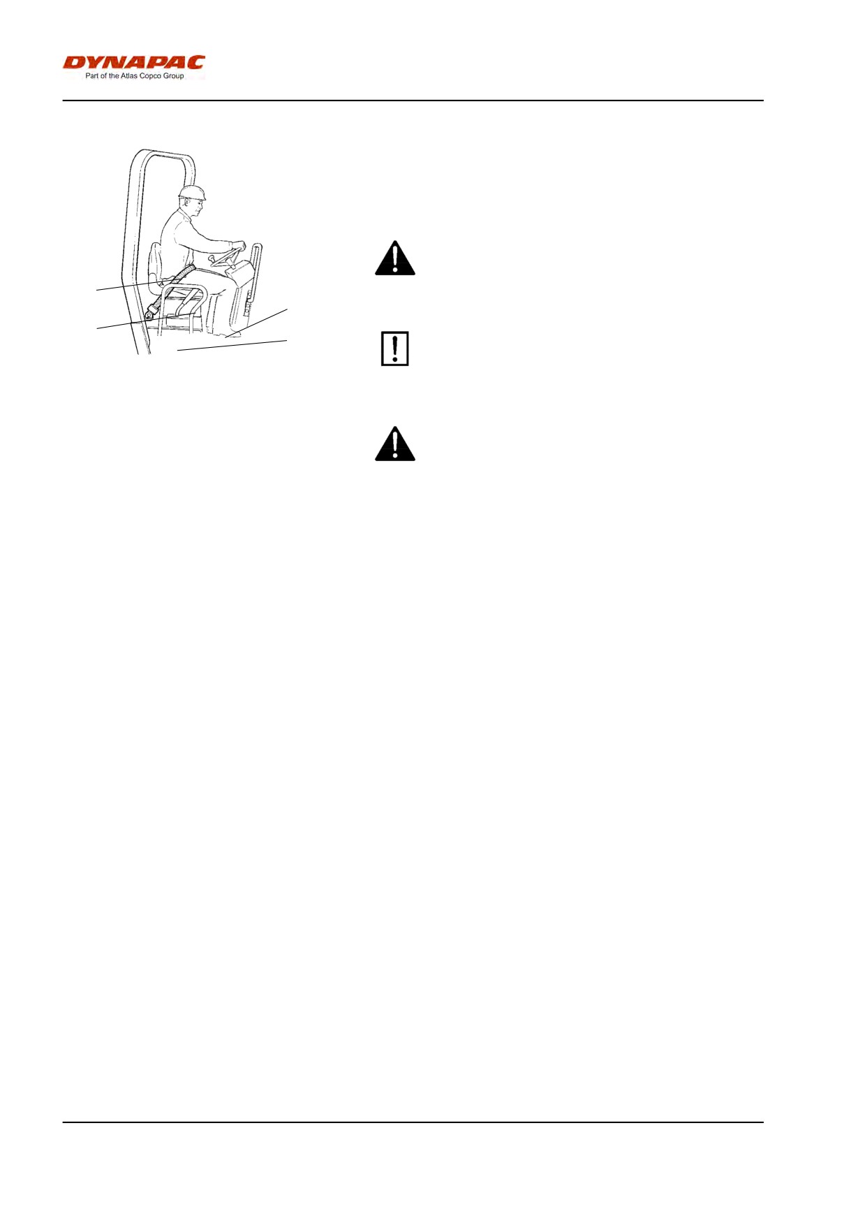
If an ROPS (Roll Over Protective Structure) is fitted to
the roller, always wear the seat belt (1) and wear a
protective helmet.
Always replace the seat belt (1) if it shows signs of
wear or has been subjected to excessive strain.
1
4
2
Check that the platform's rubber elements (3) are
3
in good condition. If the elements are worn this
Fig. Driver seat
will have a negative effect on comfort.
1. Seat belt
2. Safety rails
3. Rubber element
4. Anti-slip
Ensure that the anti-slip (4) on the platform is in
good condition. Replace where anti-slip friction is
poor.
2012-04-20
36
Operation
Starting
Starting the engine
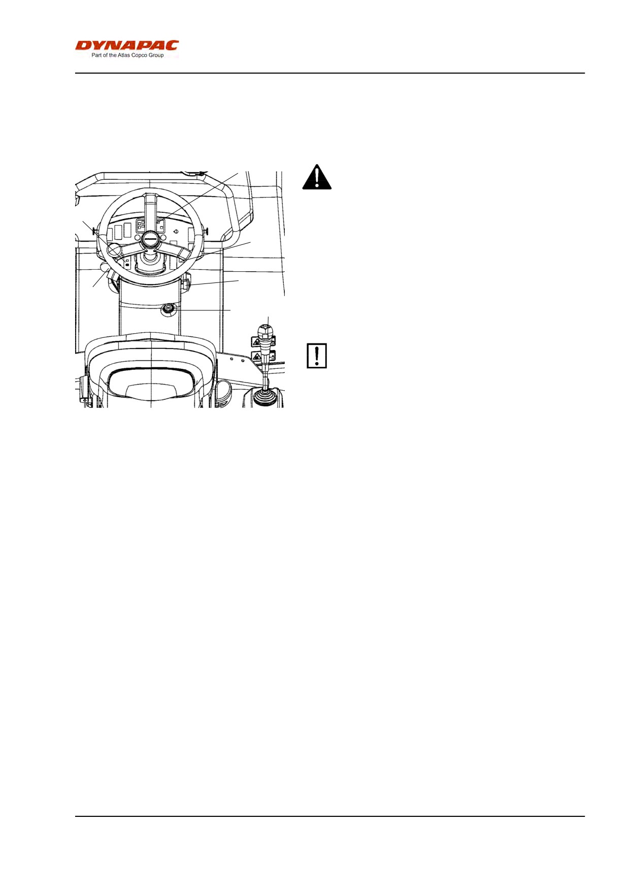
The operator must remain seated when starting.
29
31
Make sure that the emegency stop button (3) is pulled
20
out and the parking brake (31) is activated.
Set the forward/reverse lever (6) in neutral. The
3
engine can only be started when the lever is in neutral.
2
6
1
Set the vibration switch (20) for manual/automatic
vibration in (position O).
Do not run the starter motor for too long. If
the engine does not start, wait a minute or so
before trying again.
Figure. Control panel
At high ambient temperatures, set the throttle control
1. Starter switch
(2) to the position just over idling.
2. Throttle control
3. Emergency stop
Set the throttle control (2) to full speed when starting a
6. Forward/Reverse lever
cold engine. Preheating: Turn key to position II. When
20. Vibration switch man/auto
29. Glow lamp
the glow lamp (29) goes off: Turn the starter switch (1)
31. Parking brake
to the right. As soon as the engine starts, release the
starter switch and reduce the engine speed to just
over idling (because high revs can damage a cold
engine). As soon as the engine is running smoothly,
reduce the revs down to idling.
Warm up the engine at idling speed for a few minutes,
although longer if ambient temperature is below +10°C
(50°F).
2012-04-20
37
Operation
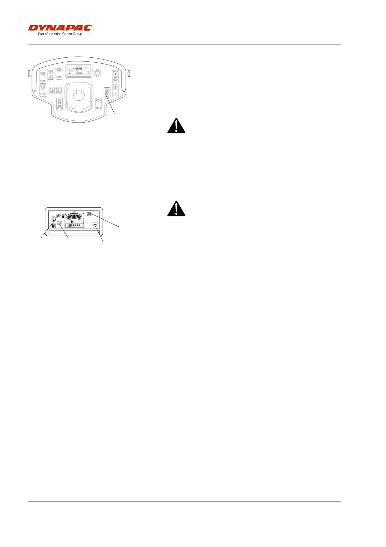
Check while warming the engine that the warning
lamps for the oil pressure (24) and charging (28) go
out.
The parking brake lamp (25) will remain on for as long
as the parking brake switch is activated.
20
When starting and driving a machine that is cold,
remember that the hydraulic fluid is also cold and
Fig. Instrument panel
that braking distances can be longer than normal
20. Vibration switch
until the machine reaches the working temperature.
Ensure that there is good ventilation (air
extraction) if the engine is run indoors. Risk of
carbon monoxide poisoning.
25
24
28
29
Fig. Control panel
24. Oil pressure lamp
25. Brake lamp
28. Charging lamp
29. Glow lamp
2012-04-20
38
Operation
Driving
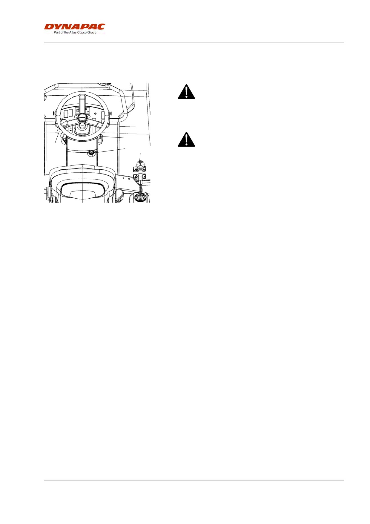
Operating the roller
Under no circumstances is the machine to be
operated from the ground. The operator must be
seated inside the machine during all operation.
Make sure that the area in front of and behind the
3
roller is clear.
2
1
6
Release the parking brake and check that the parking
brake lamp goes off.
Turn the throttle control (2) in backward position.
Figure. Instrument panel
Check that the steering is working correctly by turning
1. Starter switch
the steering wheel once to the right and once to the
2. Throttle control
left while the roller is stationary.
3. Emergency stop
6. Forward/reverse lever
When compacting asphalt, remember to turn on the
sprinkler system (12).
2012-04-20
39
Operation
Interlock/Emergency stop/Parking brake -
Check
The interlock, emergency stop and parking brake must
be checked daily before operating. A function check of
the interlock and emergency stop requires a restart.
The interlock function is checked by the operator
standing up from the seat when the roller is moving
very slowly forwards/backwards. (Check in both
directions). Hold the steering wheel firmly and brace
yourself for a sudden stop. A buzzer goes on and after
4 seconds the engine switches off and the brakes are
activated.
Check the function of the emergency stop by pressing
the emergency stop button when the roller is moving
slowly forwards/backwards. (Check in both
directions). Hold the steering wheel firmly and brace
yourself for a sudden stop. The engine switches off
and the brakes are activated.
Check the function of the parking brake by activating
the parking brake when the roller is moving very
slowly forwards/backwards. (Check in both
directions). Hold the steering wheel and brace yourself
for a sudden stop when the brakes are activated. The
engine does not switch off.
Vibration
Manual/Automatic vibration
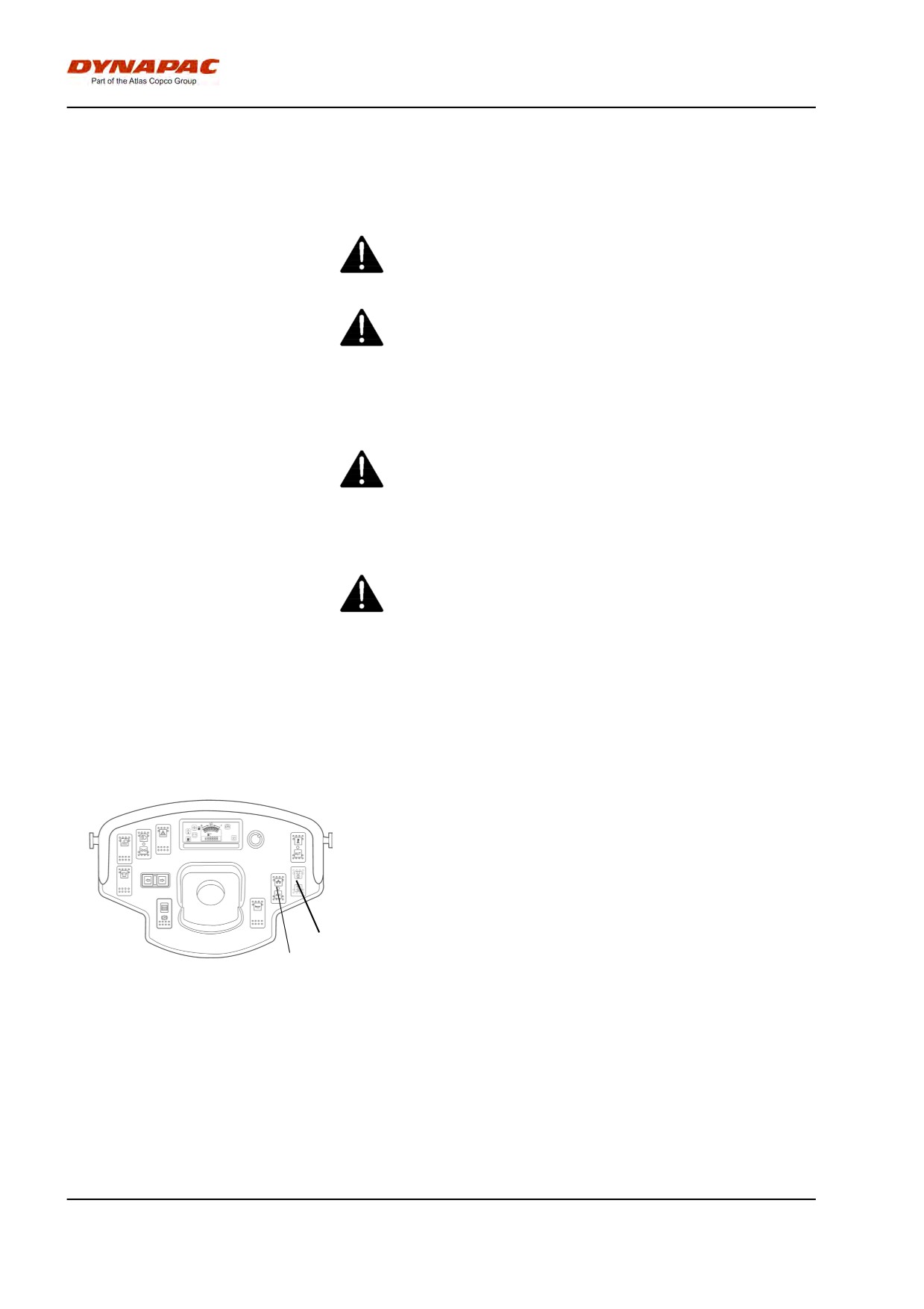
Manual or automatic vibration activation/deactivation is
selected using switch (20).
In the manual position, the operator must activate the
vibration using the switch on underside of the
forward/reverse lever grip.
In the automatic position, vibration is activated when
the pre-set speed is reached. Vibration is
21
automatically deactivated when the lowest pre-set
20
speed is reached.
Fig. Instrument panel
20. Man/Auto switch
21. Switch, Vibration selector
2012-04-20
40
Operation
Vibration on one drum (Optional)
The switch (21) is used to select vibration with the rear
drum only, or with two drums.
When the vibration is on, the operator must activate
vibration via the switch (20) on the forward/reverse
lever.
In the lower position the vibration is activated on both
drums.
In the upper position the vibrationen on the front drum
is switched off.
Braking
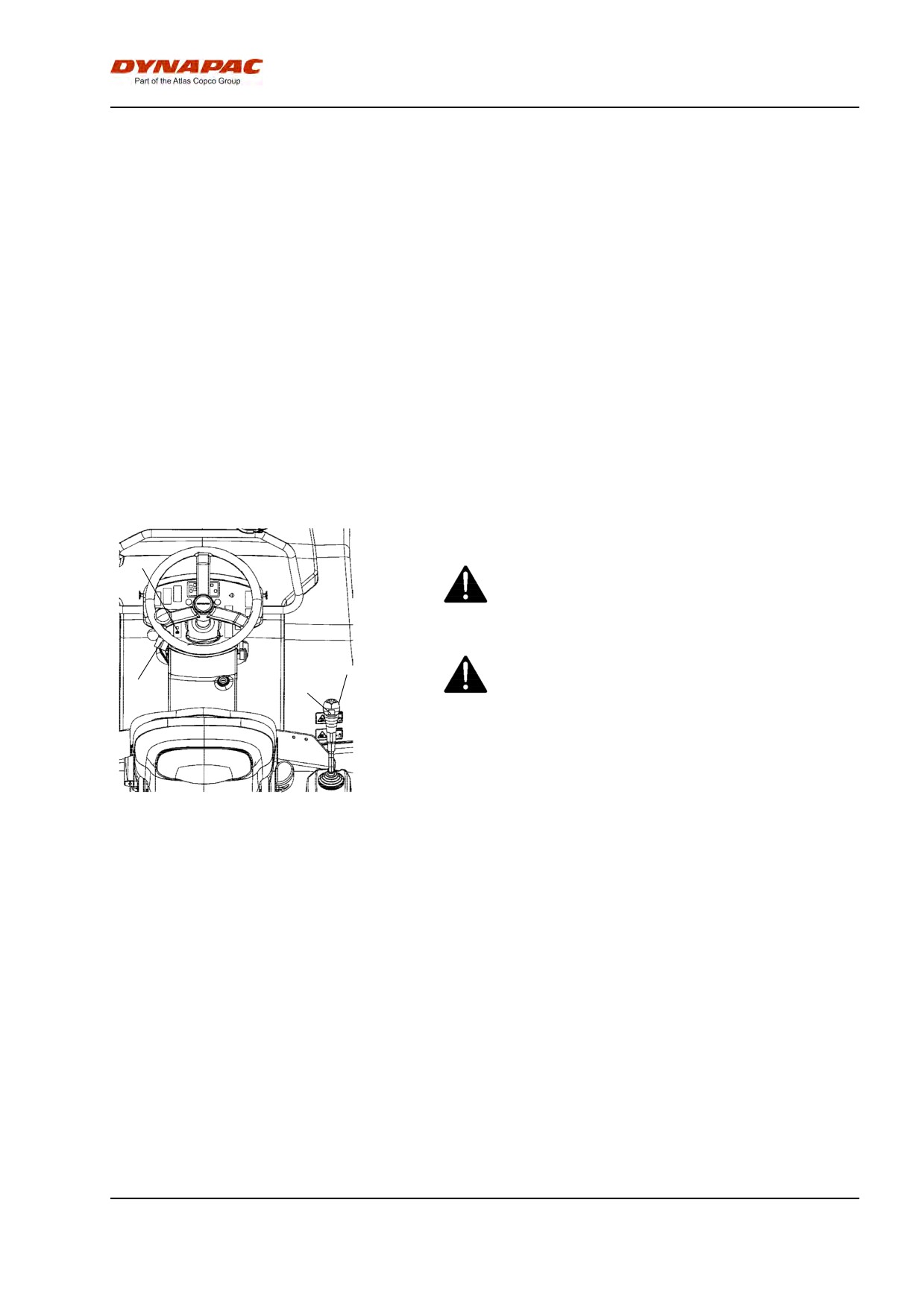
Normal braking
Press the switch (4) to switch off the vibration.
Move the forward/reverse lever (6) to the neutral
position to stop the roller.
31
When starting and driving a machine that is cold,
remember that the hydraulic fluid is also cold and
that braking distances can be longer than normal
until the machine reaches the working temperature.
6
Never leave the operator platform without
activating the parking brake (31).
2
4
Figure. Control panel
2. Throttle control
4. Vibration On/off
6. Forward/reverse lever
31. Parking brake
2012-04-20
41
Operation
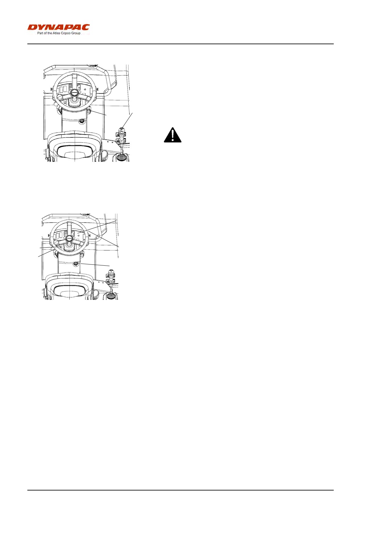
Emergency braking
Braking is normally activated using the
forward/reverse lever (6). The hydrostatic transmission
brakes the roller when the lever is moved to the
neutral position.
There is a brake in each drum motor that acts as an
6
emergency brake during operation.
3
To brake in an emergency situation, push in the
emergency stop knob (3), hold the steering wheel
firmly and be prepared for a sudden stop. The
diesel engine stops.
Fig. Control panel
3. Emergency stop
After emergency braking, reset the forward/reverse
6. Forward/Reverse lever
lever (6) to neutral position, pull out the emergency
stop button and activate the parking brake. Restart the
engine.
Switching off
22
Turn the throttle control (2) back to idling. Allow the
engine to idle for a few minutes to cool.
31
9
Activate the parking brake (31).
2
1
Check instruments and warning lamps to see if any
faults are indicated. Switch off all lights and other
electrical functions.
Figure. Instrument panel
Turn the starter switch (1) to the left to the switched off
1. Starter switch
position. At the end of the shift, fold over the
2. Throttle control
instrument cover (9) and lock.
9. Instrument cover
22. Panel for warning lamps
31. Parking brake
2012-04-20
42
Operation
Parking
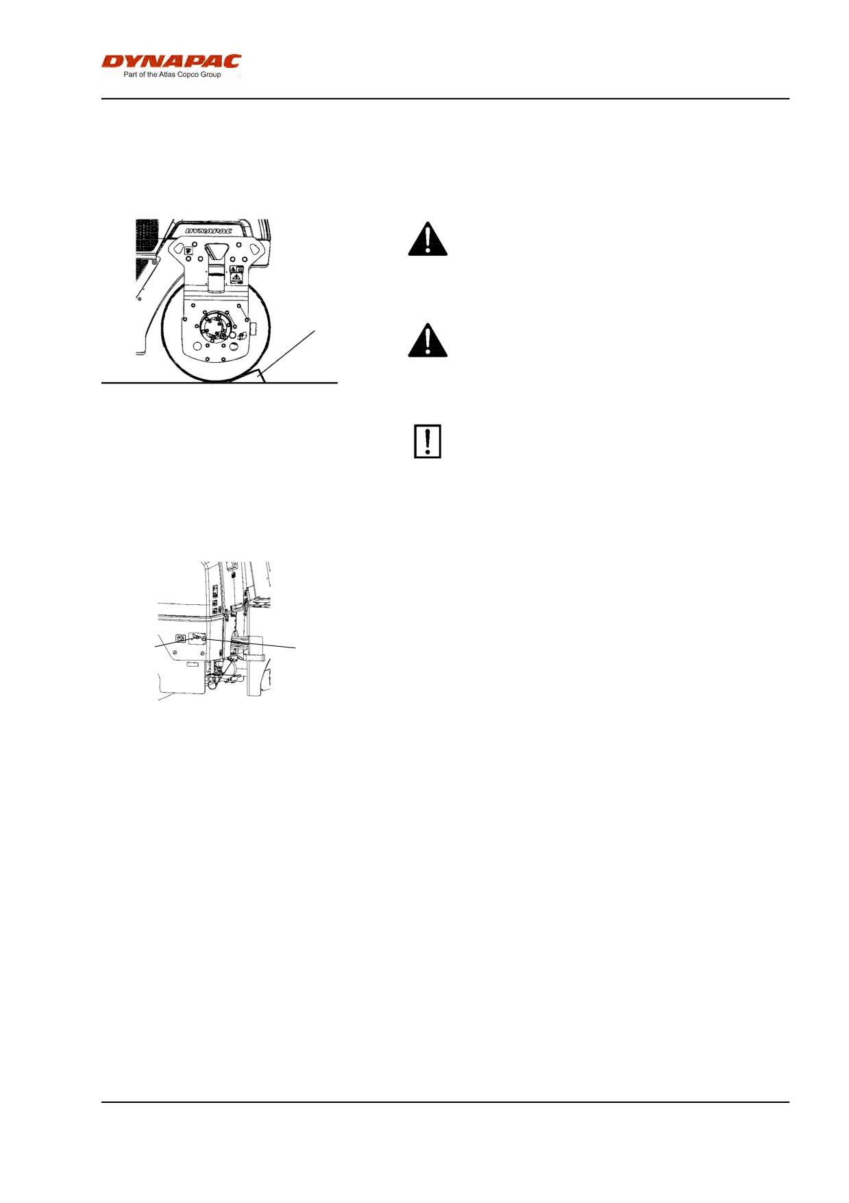
Chocking the drums
Never disembark from the roller when the diesel
engine is running, without first activating the
parking brake.
1
Make sure that the roller is parked in a safe place
with respect to other road users. Chock the drums
if the roller is parked on sloping ground.
Fig. Drum part
1. Chocks
Remember that there is a risk of freezing during
the winter. Empty the water tank. Fill antifreeze in
the engine's cooling system. See also
maintenance instructions.
Battery disconnector
Before leaving the roller at the end of the shift, switch
off the battery disconnector (1) and remove the key.
This will prevent battery discharging and will also
make it difficult for unauthorized persons to start and
1
2
operate the machine. Lock also the engine cover.
Fig. Battery bay
1. Battery disconnector
2. Power socket, 12 V
2012-04-20
43
Operation
2012-04-20
44
Long-term parking
Long-term parking
The following instructions should be followed
when long term parking (more than one month).
These measures apply when parking for a period of up
to 6 months.
Before re-commissioning the roller, the points marked
with an asterisk * must be returned to the pre-storage
state.
Wash the machine and touch up the paint finish to
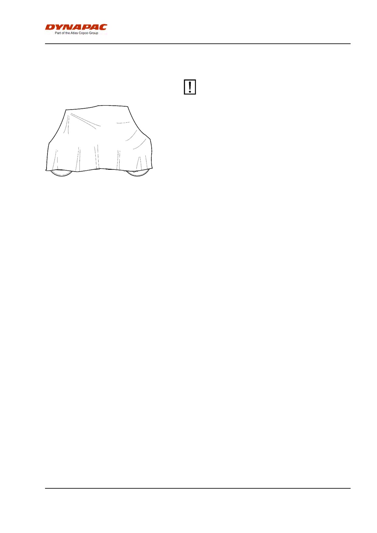
Fig. Roller weather protection
avoid rusting.
Treat exposed parts with anti-rust agent, lubricate the
machine thoroughly and apply grease to unpainted
surfaces.
Engine
* Refer to the manufacturer’s instructions in the engine
manual that is supplied with the roller.
Battery
* Remove the battery/battteries from the machine,
clean the outside and trickle charge once a month.
Air cleaner, exhaust pipe
* Cover the air cleaner (see under the heading 'Every
50 hours of operation' or 'Every 1000 hours of
operation') or its opening with plastic or tape. Also
cover the exhaust pipe opening. This is to avoid
moisture entering the engine.
Fuel tank
Fill the fuel tank completely full to prevent
condensation.
Hydraulic reservoir
Fill the hydraulic reservoir to the uppermost level mark
(see under the heading ‘Every 10 hours of operation.’)
Water tank
Empty the water tank completely to avoid fouling.
2012-04-20
45
Long-term parking
Steering cylinder, hinges, etc.
Lubricate the steering joint bearings and both bearings
on the steering cylinder with grease (see under the
heading 'Every 50 hours of operation').
Grease the steering cylinder piston with conservation
grease.
Grease the hinges on the doors to the engine
compartment and the cab. Grease both ends of the
forward/reverse control (bright parts) (see under the
heading 'Every 500 hours of operation').
Hoods, tarpaulin
* Lower the instrument cover over the instrument
panel.
* Cover the entire roller with a tarpaulin. A gap must
be left between the tarpaulin and the ground.
* If possible, store the roller indoors and ideally in a
building where the temperature is constant.
2012-04-20
46
Miscellaneous
Miscellaneous
Lifting
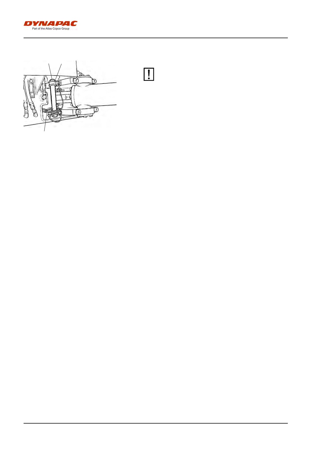
1
Locking the articulation
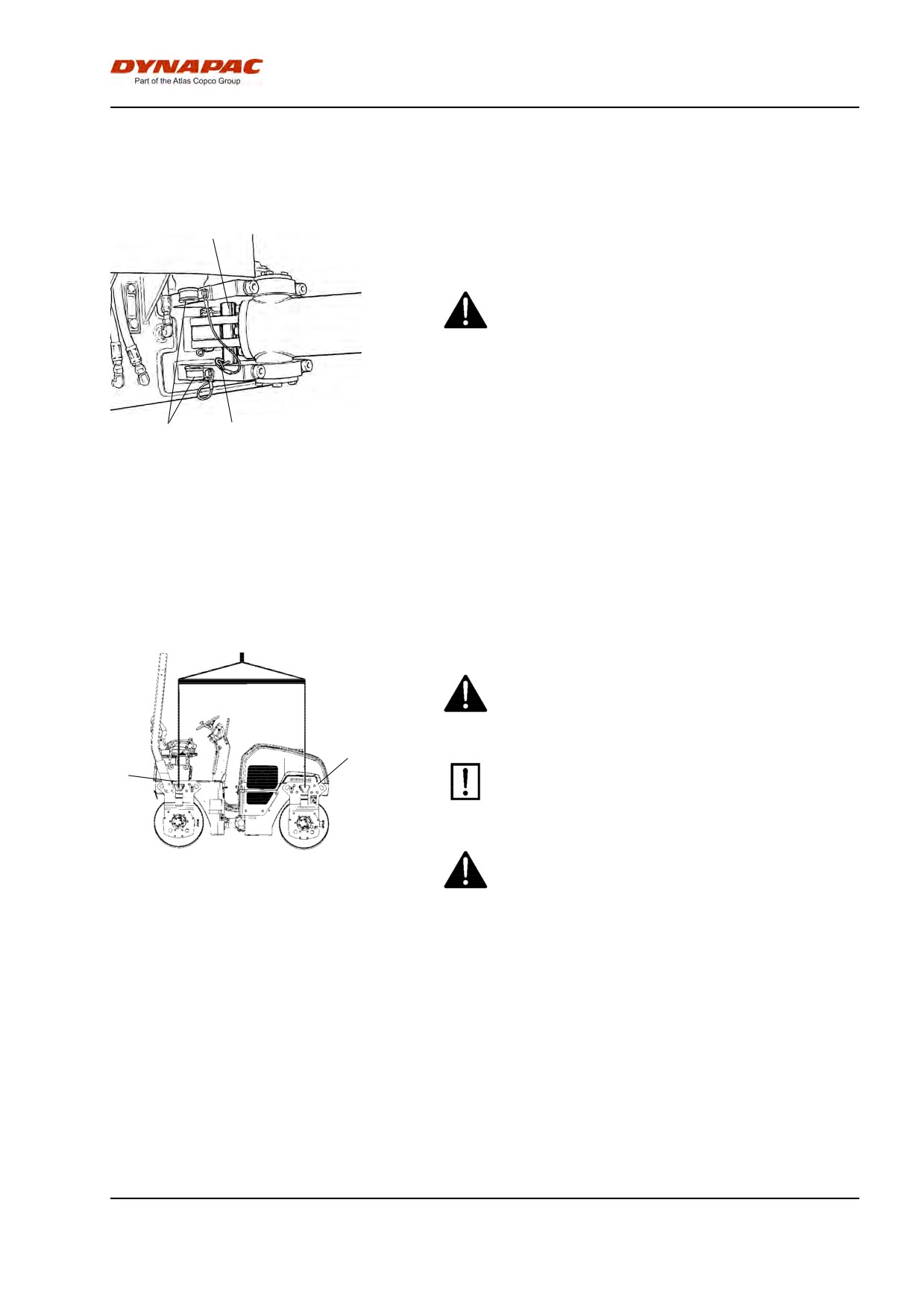
Before lifting the roller the steering joint must be
locked to prevent it turning.
Turn the steering wheel to the straight ahead position.
Switch off the machine and activate the parking brake.
3
2
Pull down the galvanized lock bar (1) from its holder
Fig. Left side of steering joint
(3), and place it from underneath in the hole on the
1. Lock bar
2. Lock pin
lower steering joint bracket. Press the bar through until
3. Holder
the upper end is visible in the hole on the upper
steering joint bracket.
Secure the bar with the lock pin (2).
Weight: refer to the hoisting plate on the
roller
Lifting the roller
The weight of the machine is shown on the lifting
plate (1). See also Technical specifications.
1
1
Lifting equipment such as chains, steel wires,
straps and lifting hooks must be dimensioned in
accordance with the relevant safety regulations
for the lifting equipment.
Stand well clear of the hoisted machine! Make sure
that the lifting hooks are properly secured.
Fig. Lifting the roller
1. Lifting plate
2012-04-20
47
Miscellaneous
Unlocking the articulation
1
3
Remember to refit the lock bar (1) in its holder
after operation.
2
Fig. Left side of steering joint
1. Lock bar
2. Lock pin
3. Holder
2012-04-20
48
Miscellaneous
Towing/Recovering
The roller can be moved up to 300 meters (1,000 ft)
using the instructions below.
Release the brakes
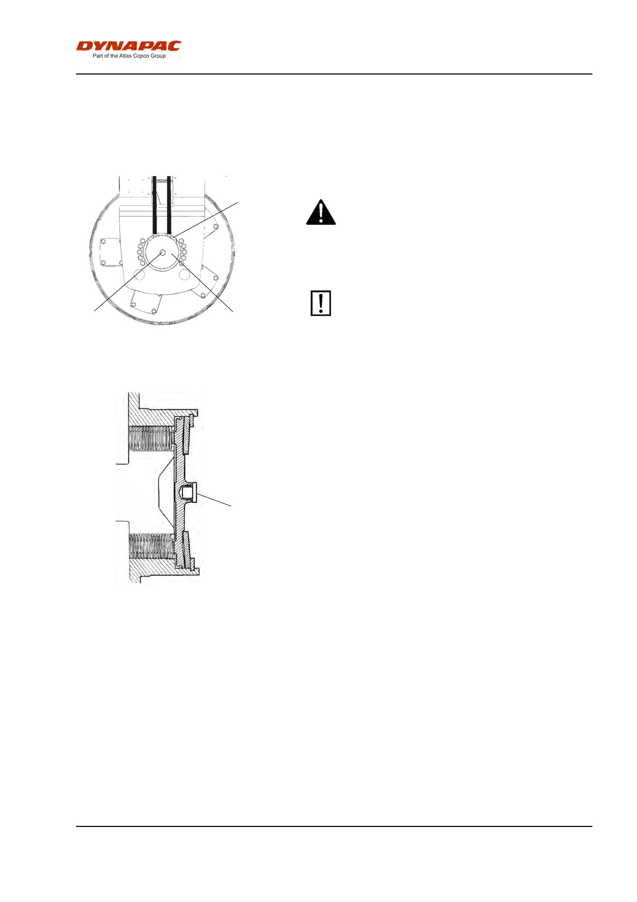
3
Activate the parking brake, and stop the engine.
Block the drum with a chock to prevent movement;
the roller can start rolling when the brakes are
released.
The disc brake in each drive motor must be
disengaged mechanically, according to below
1
2
following instructions, before the roller can be
towed.
Fig. Left side of drum
1. Brake tool
2. Fastening screw
3. Disengagement nut
Remove the center plug (4) using a screwdriver.
Screw off the brake tool (1) from its threaded fixing
hole. Then fix the brake tool (1) in the center hole by
tightening the screw (2) until it bottoms in the hole.
Tighten the nut (3) against the brake tool until it stops,
indicating that the brakes is now disengaged.
4
Disengaging the brakes
Screw out the nut again after towing. This returns the
brakes to their normal mode. Screw off the brake tool
and fit it back into its fixing holes. Refit the center plug
(4) to counteract the information of rust inside the
threaded hole.
Fig. Brake housing
4. Center plug
2012-04-20
49
Miscellaneous
Releasing the brake, High torque motor
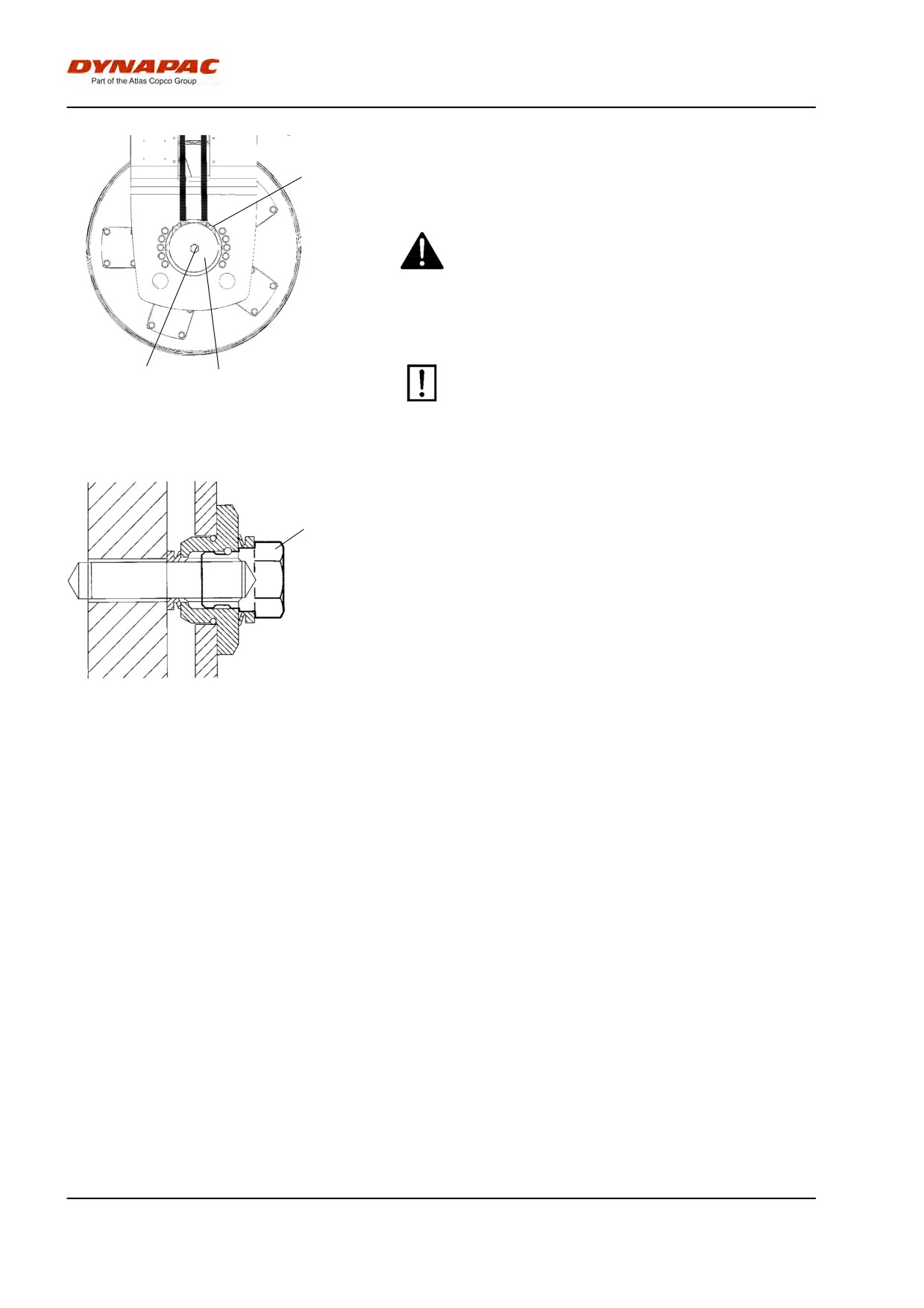
3
(Optional) (p/n 4700380594)
Activate the parking brake, and stop the engine.
Block the drum with a chock to prevent movement;
the roller can start rolling when the brakes are
released.
The disc brakes in each drive motor must be
1
2
released mechanically as shown below before the
Fig. Left drum side
towing the roller.
1. Release screw
2. Brake housing
3. Drive motor
Use a key with an 18 mm socket.
1
Disengaging the brakes
Turn the same screws a 1 1/2 turn anticlockwise to
activate the brakes again after towing.
Fig. Brake housing
1. Release screw
2012-04-20
50
Miscellaneous
Release the brakes on both drums.
Turn the release screw (1) a 1 1/2 turn clockwise to
release the brake.
Towing the roller
The roller must be counter-braked during
towing/recovery. Always use a towbar. There is no
braking capacity on the roller now.
The roller must be towed slowly, max. 3 kph (2
mph) and only towed short distances, max. 300 m
(1000 ft).
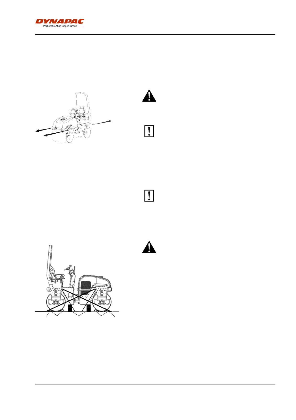
Fig. Towing
When towing/retrieving a machine, the towing device
must be connected to both lifting holes. The pulling
force shall act longitudinally on the machine as shown
in the figure. Maximum total pulling force 130 kN
(29225 lbf).
Reverse the towing preparations.
Roller prepared for transport
Lock the articulation before lifting and
transporting. Follow the instructions under the
relevant heading.
Activate the parking brake.
Make sure that the machine is in a neutral position, i.e.
that the drums are in line.
Chock the drums (1) and secure the chocks to the
transport vehicle. The drums should be chocked both
forwards and backwards.
3
1
2
1
3
Block up under the drum frame (2), to avoid
Fig. Arrangement
overloading the rubber suspension when lashing.
1. Chocks
Block up the machine as shown in figure.
2. Wooden blocks
3. Lashing straps
Secure down the roller with lashing straps (3) at all
four corners. The attachment points are shown on the
decals. Place the chains in symmetrical pairs crossing
each other.
2012-04-20
51
Miscellaneous
Make sure that the chains, blocks and
attachments in the transport vehicle are approved
and have the requisite breaking strain. Check at
regular intervals that the chains are not slack.
Remember to reset the steering joint lock to its
open position before starting the roller again.
Retractable ROPS (Optional)
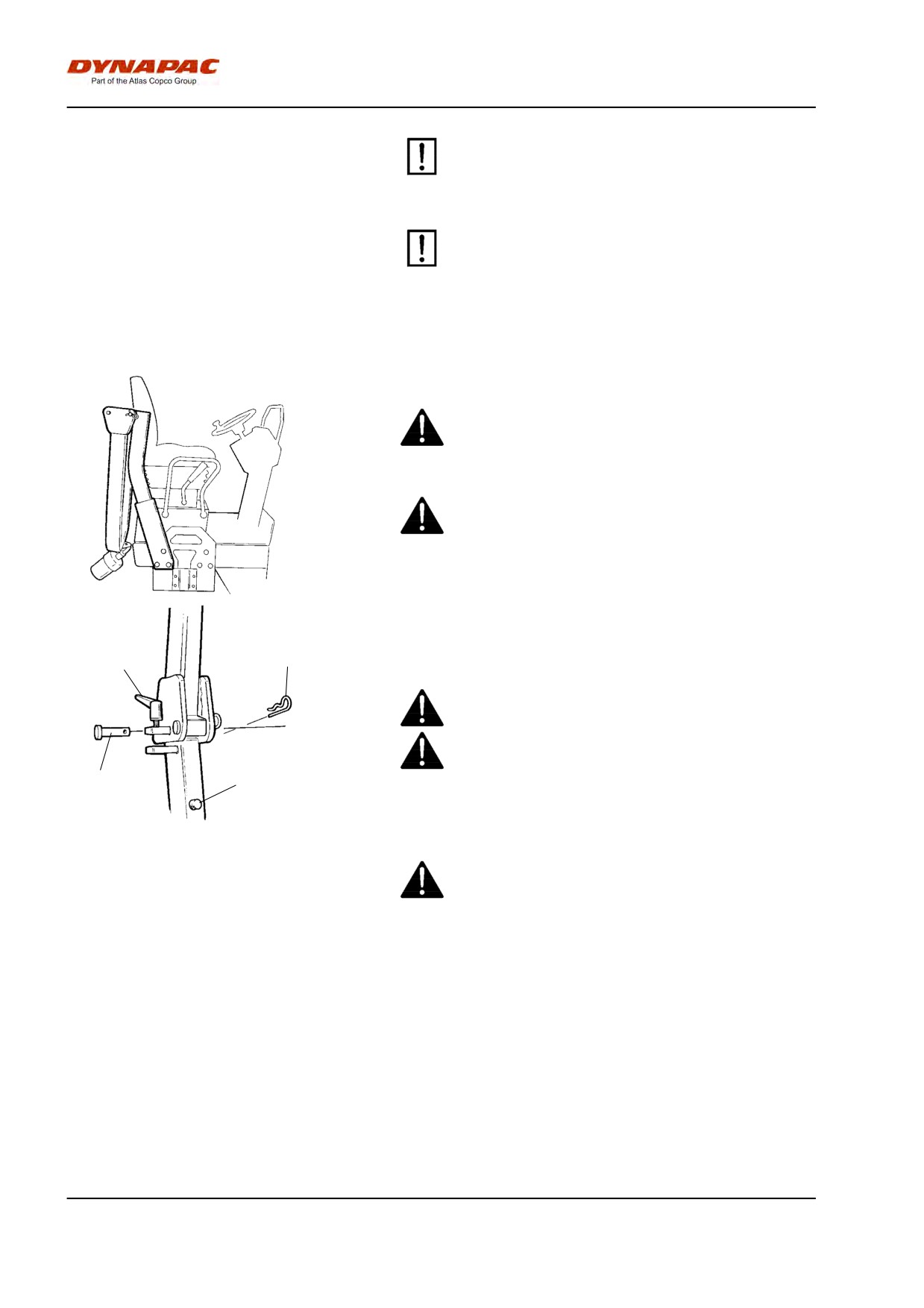
The machine can be equipped with retractable ROPS.
Risk of crush injury when raising and lowering
ROPS.
If the roller is equipped with a retractable ROPS,
the machine must only be operated when it is lifted
up and locked.
Fig.
To retract the ROPS, release the tensioning screw (1),
and pull out the pin (2) and stud (3). Do the same on
2
both sides. Lower the ROPS backwards if there is
1
space.
Remember to dismantle the rotating warning light
before lowering the ROPS.
After lowering the ROPS, replace the pin and stud.
3
4
Fig. ROPS locking device
1. Tensioning screw
To lift the ROPS proceed in the reserve order.
2. Pin
Always make sure the ROPS is locked in raised
3. Stud
position before operation.
4. Rubber buffer
Grease the tensioning screw (1) and stud (3)
periodically.
2012-04-20
52
Operating instructions - Summary
Operating instructions - Summary
1.
Follow the SAFETY INSTRUCTIONS specified in the Safety Manual.
2.
Make sure that all instructions in the MAINTENANCE section are followed.
3.
Turn the master switch to the ON position.
4.
Move the forward/reverse lever to the NEUTRAL position.
5.
Set the switch for Manual/Automatic vibration to the 0 position.
6.
Set the throttle control to more than half.
7.
Set the emergency stop brake button in the pulled out position.
8.
Start the engine and allow it to warm up.
9.
Set the throttle control to the operating position.
10. Drive the roller. Operate the forward/reverse lever with care.
11. Check the brakes, drive slowly. Remember that the braking distance will be
longer if the roller is cold.
12. Use vibration only when the roller is in motion.
13. Check that the drum and wheels are thoroughly watered when watering is required.
14. IN AN EMERGENCY:
- Press the EMERGENCY STOP BUTTON
- Hold the steering wheel firmly.
- Brace yourself for a sudden stop. The engine stops.
15. Parking: - Stop the engine,chock the drum and wheels.
16. When lifting: - Refer to the relevant section in the Instruction Manual.
17. When towing: - Refer to the relevant section in the Instruction Manual.
18. When transporting: - Refer to the relevant section in the Instruction Manual.
19. When recovering - Refer to the relevant section in the Instruction Manual.
2012-04-20
53
Operating instructions - Summary
2012-04-20
54
Preventive maintenance
Preventive maintenance
Complete maintenance is necessary for the machine
to function satisfactorily and at the lowest possible
cost.
The Maintenance section includes the periodic
maintenance that must be carried out on the machine.
The recommended maintenance intervals assume that
the machine is used in a normal environment and
working conditions.
Acceptance and delivery inspection
The machine is tested and adjusted before it leaves
the factory.
On arrival, before delivery to the customer, delivery
inspection must be conducted as per the check list in
the warranty document.
Any transport damage must be immediately reported
to the transport company.
Warranty
The warranty is only valid if the stiplulated delivery
inspection and the separate service inspection have
been completed as per the warranty document, and
when the machine has been registered for starting
under the warranty.
The warranty is not valid if damage has been caused
by inadequate service, incorrect use of the machine,
the use of lubricants and hydraulic fluids other than
those specified in the manual, or if any other
adjustments have been made without the requisite
authorisation.
2012-04-20
55
Preventive maintenance
2012-04-20
56
Maintenance - Lubricants and symbols
Maintenance - Lubricants and symbols
Fluid volumes
Hydraulic tank
45 liters
47.5 qts
Diesel engine
7 liters
7.4 qts
Drum
4 liters
4.2 qts
Coolant
5,5 liter
5.8 qts
Always use high-quality lubricants and the
amounts recommended. Too much grease or
oil can cause overheating, resulting in rapid
wear.
DYNAPAC
ENGINE OIL
Air temperature -15°C - +50°C
Shell Rimula R4 L
(5°F-122°F)
15W-40, API CH-4 or
equivalent.
HYDRAULIC FLUID
Air temperature -15°C - +50°C
Shell Tellus S2 V68 or
(5°F-104°F)
equivalent.
Air temperature over +50°C
Shell Tellus S2 V100 or
(104°F)
equivalent.
BIOLOGICAL
When it leaves the factory, the
PANOLIN HLP Synth 46
HYDRAULIC FLUID,
machine may be filled with
PANOLIN
biologically degradable fluid.
The same type of fluid must be
used when changing or topping
up.
DRUM OIL
Air temp. -15°C - +40°C
Shell Spirax S3 AX
Dynapac Drum Oil 1000,
(5°F-104°F)
80W/90, API GL-5
P/N 4812156456 (5 liter)
Air temperature 0°C - over
Shell Spirax AX
+40°C (32°F- over 104°F)
85W/140, API GL-5
GREASE
Shell Retinax LX2 or
Dynapac Roller Grease
equivalent.
(0.4kg),
P/N 4812030096
FUEL
See engine manual.
-
-
COOLANT
Anti-freeze protection down to
GlycoShell/Carcoolant
about -37°C (-34.6°F)
774C or equivalent,
(mixed 50/50 with water)
Other fuel and lubricants are required when
operating in areas with extremely high or
extremely low ambient temperatures. See the
‘Special instructions’ chapter, or consult
Dynapac.
2012-04-20
57
Maintenance - Lubricants and symbols
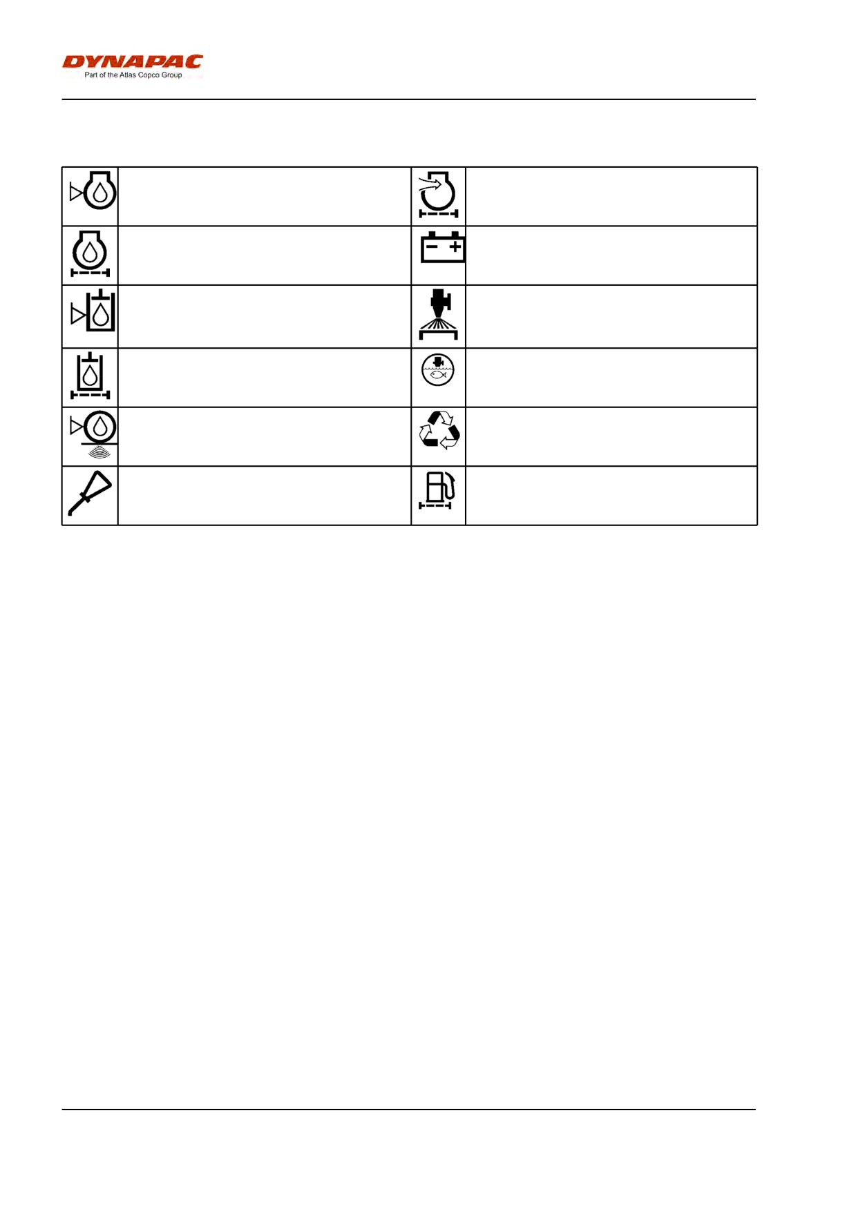
Maintenance symbols
Engine, oil level
Air filter
Engine, oil filter
Battery
Hydraulic reservoir, level
Sprinkler
Hydraulic fluid, filter
Sprinkler water
Drum, oil level
Recycling
Lubricating oil
Fuel filter
2012-04-20
58
Maintenance - Maintenance schedule
Maintenance - Maintenance schedule
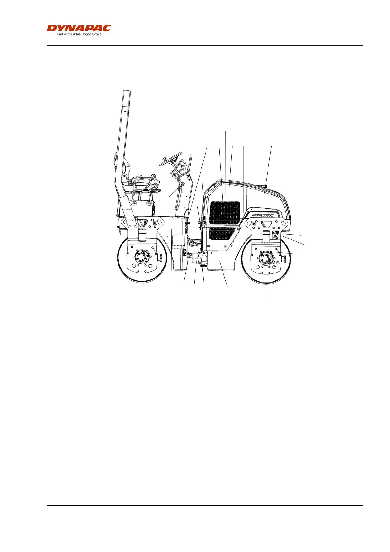
Service and maintenance points
6
2
3
4
5
7
11
19
13
8
9
10
1
16
14
15
12
17
18
Fig. Service and maintenance points
1.
Fuel tank
8.
Sprinkler system
15. Steering joint
2.
Refueling
9.
Scrapers
16. Steering cylinder bracket
3.
Cooler
10. Shock absorbers and
17. Filler plugs/Drum
attachment screws
4.
Air cleaner
11. Hydraulic fluid refilling
18. Oil level in drum
5.
Battery
12. Hydraulic fluid tank
19. Emergency stop
6.
Diesel engine
13. Hydraulic fluid filter
7.
Water tank
14. Hydraulic fluid level glass
2012-04-20
59
Maintenance - Maintenance schedule
General
Periodic maintenance should be carried out after the
number of hours specified. Use the daily, weekly etc.
periods where number of hours cannot be used.
Remove all dirt before filling, when checking
oils and fuel and when lubricating using oil or
grease.
The manufacturer’s instructions found in the
engine manual also apply.
Every 10 hours of operation (Daily)
Refer to the contents to find the page number of the
sections referred to !
Pos.
Action
Comment
in fig
Before starting up for the first time on that day
6
Check the engine oil level
Refer to the engine manual
14
Check the hydraulic reservoir level
3
Check for free circulation of cooling air
1
Fill the fuel tank
7
Fill the water tank
8
Check the sprinkler system
9
Check the scraper setting
19
Test the brakes
After the FIRST 50 hours of operation
See Contents to find the page number of the sections
referred to!
Pos.
Action
Comment
in fig
6
Change the engine oil and oil filter
Refer to the engine manual
6
Change the fuel filter
Refer to the engine manual
13
Change the hydraulic fluid filter
10
Check bolted joints
2012-04-20
60
Maintenance - Maintenance schedule
Every 50 hours of operation (Weekly)
See Contents to find the page number of the sections
referred to!
Pos.
Action
Comment
in fig
4
Check indicator for air cleaner
Check that the air hoses are in good condition and
that the connections are tight
15
Grease the steering joint
16
Grease the steering cylinder brackets
Every 250 hours of operation (Monthly)
See Contents to find the page number of the sections
referred to!
Pos.
Action
Comment
in fig
3
Clean the outside of the radiator core
In duty environments, as
necessary
5
Check the battery condition
6
Change the engine oil and oil filter
Refer to the engine manual
Every 500 hours of operation (Every three
months)
See Contents to find the page number of the sections
referred to!
Pos.
Action
Comment
in fig
18
Check the oil level in the drums
10
Check rubber elements and bolted joints
11
Check the hydraulic reservoir cover/breather
6
Lubricate hinges and controls
6
Check engine's V-belt
Refer to the engine manual
3
Check coolant freezing point. Change the coolant
every other year
2012-04-20
61
Maintenance - Maintenance schedule
Every 1000 hours of operation (Every six
months)
See Contents to find the page number of the sections
referred to!
Pos.
Action
Comment
in fig
13
Change the hydraulic fluid filter
12
Drain condensate from hydraulic tank
6
Change the engine's fuel filter
6
Change the engine's pre-filter
6
Check the engine's toothed belt
Refer to the engine manual
6
Check engine's valve clearances
Refer to the engine manual
Every 2000 hours of operation (Yearly)
See Contents to find the page number of the sections
referred to!
Pos.
Action
Comment
in fig
12
Change the hydraulic fluid
18
Change the oil in the drums
7
Drain and clean the water tank
1
Drain and clean the fuel tank
Check the condition of the articulation
2012-04-20
62
Maintenance, 10h
Maintenance, 10h
Park the roller on a level surface.
The engine must be switched off and the
parking brake activated when checking or
adjusting the roller, unless otherwise specified.
Ensue that there is good ventilation (air
extraction) if the engine is run indoors. Risk of
carbon monoxide poisoning.
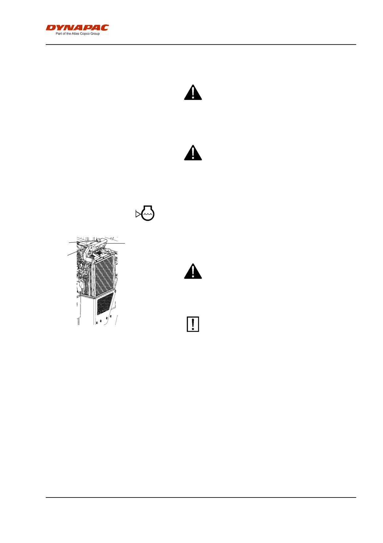
Check - Coolant system
1
2
Check that all hoses/hose connectors are intact and
tight. Fill with coolant as specified in the lubricants
2
specification.
Take great care when opening the radiator cap
while the engine is hot. Wear protective gloves and
goggles.
Also check the freezing point. Change the coolant
every other year.
Figure. Cooling water container
1. Filler cap
2. Level marking
2012-04-20
63
Maintenance, 10h
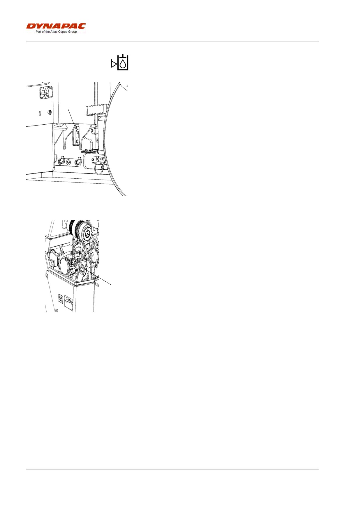
Hydraulic reservoir, Level check - Filling
Check that the level is between the min and max
markings. Top up with hydraulic fluid as per lubricant
specifications if level is too low.
1
Fig. Hydraulic fluid tank
1. Sight glass
Open the engine hood and unscrew the filler cap, top
up with hydraulic fluid (as per lubricant specification) if
the level is too low.
1
Fig. Engine compartment
1. Hydraulic fluid refilling
2012-04-20
64
Maintenance, 10h
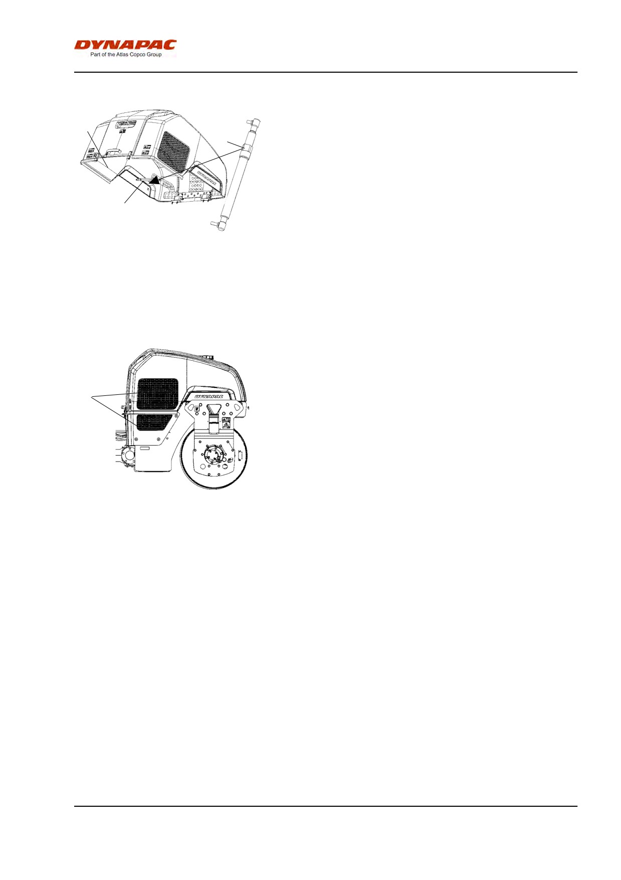
Lowering of engine hood
Stand on the left side of the engine hood. Press in the
red button (3) and carefully lower the engine hood
1
until the gas spring (2) goes into the slot. Release the
3
red button (3) and then lower down the engine hood
completely.
2
Fig. Engine compartment
1. Engine hood
2. Gas spring
3. Button
Air circulation - Check
Check that the engine has free circulation of cooling
air through the grille (1) in the engine compartment.
1
Fig. Right drum side
1. Cooling air grille
2012-04-20
65
Maintenance, 10h
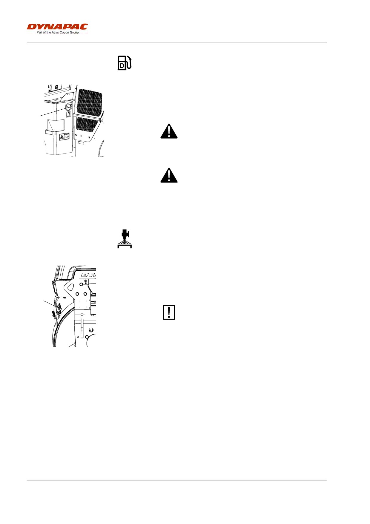
Fuel tank - Filling
Refuel every day before starting to work. Screw off the
lockable tank cap (1) and fill diesel fuel to the lower
edge of the filler pipe.
1
Stop the diesel engine. Short-circuit (press) the
filler gun against a non-insulated part of the roller
before refuelling, and against the filler pipe while
refuelling.
Fig. Fuel tank
1. Filler cap
Never refuel while the engine is running. Do not
smoke and avoid spilling fuel.
The fuel tank holds 50 liters.
Sprinkler system/Drum
Checking - Cleaning
Start the sprinkler system and make sure that no
nozzles (1) are clogged. If necessary, clean clogged
nozzles and the coarse filter located by the water
pump; see figures below.
1
The sprinkler system
should be drained if there
is a risk of freezing.
Fig. Drum
1. Nozzle
2012-04-20
66
Maintenance, 10h
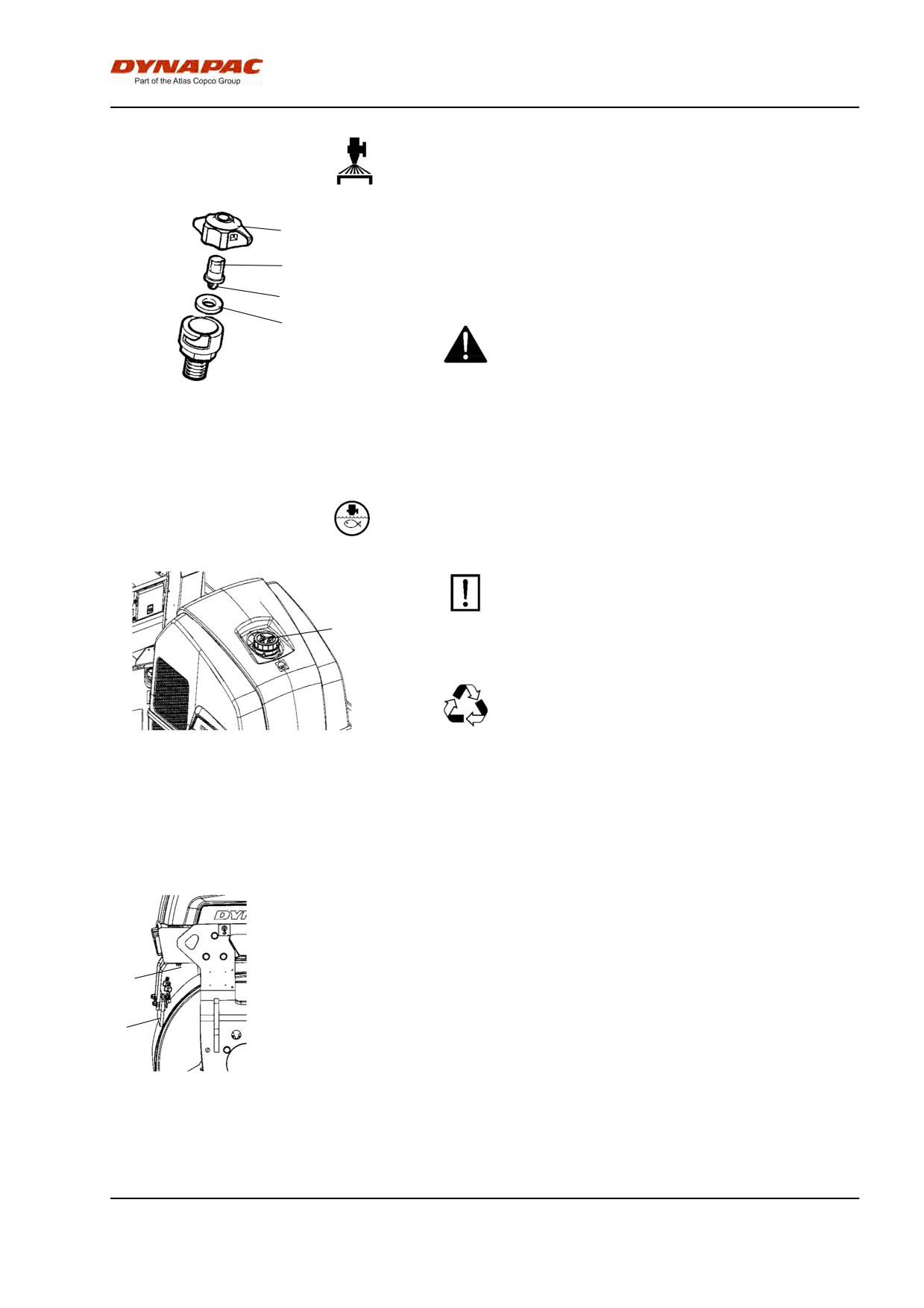
1
Dismantle the blocked nozzle by hand. Blow the
nozzle (2) and fine filter (4) clean with compressed air,
2
or install replacement parts and clean the clogged
parts later.
4
3
Wear protective goggles when working with
compressed air.
Fig. Nozzle
1. Sleeve
2. Nozzle
3. Gasket
4. Strainer
Water tank - Filling
Unscrew the tank cap (1) and fill with clean water.
Do not remove the strainer. See technical
specifications for the tank volume.
1
Only additive: A small amount of
environment-friendly antifreeze.
Fig. Water tank
1. Tank cap
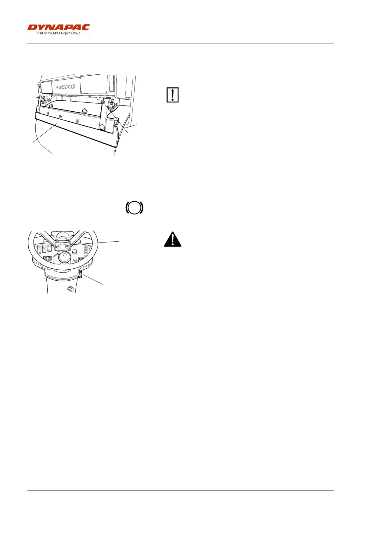
Scrapers, fixed
Checking - Setting
Make sure that the scrapers are undamaged. Adjust
the scrapers so that they are 1-2 mm from the drum.
For special asphalt compounds, it may be better if the
2
scraper blades (1) lie lightly against the drums.
Asphalt remnants can accumulate on the scraper and
1
affect the contact force. Clean as required.
Loosen the screws (2) to adjust the contact pressure
of the scraper blade against the drum.
Fig. Drum
Remember to tighten all the screws after any
1. Scraper blade
2. Adjusting screws
adjustment.
2012-04-20
67
Maintenance, 10h
Scrapers, spring-action (Optional)
Checking - Adjustment
The scrapers must be lifted from the drum during
2
transport.
2
1
Fig. Spring-action scrapers
1. Scraper blade
2. Adjusting screws
Brakes - Check
Check operation of the brakes as follows:
25
Run the roller very slowly forward. Hold the steering
wheel firmly and brace yourself for a sudden stop.
3
Press in the emergency stop button (3). The roller will
Figure. Instrument panel
stop abruptly and the engine will switch off.
3. Emergency stop
25. Parking brake lamp
After testing the brakes, set the forward/reverse lever
in neutral.
Pull out the emergency stop button (3). Start the
engine.
The roller is now ready for operation.
Refer also to the section in the manual on operation.
2012-04-20
68
Maintenance, 10h
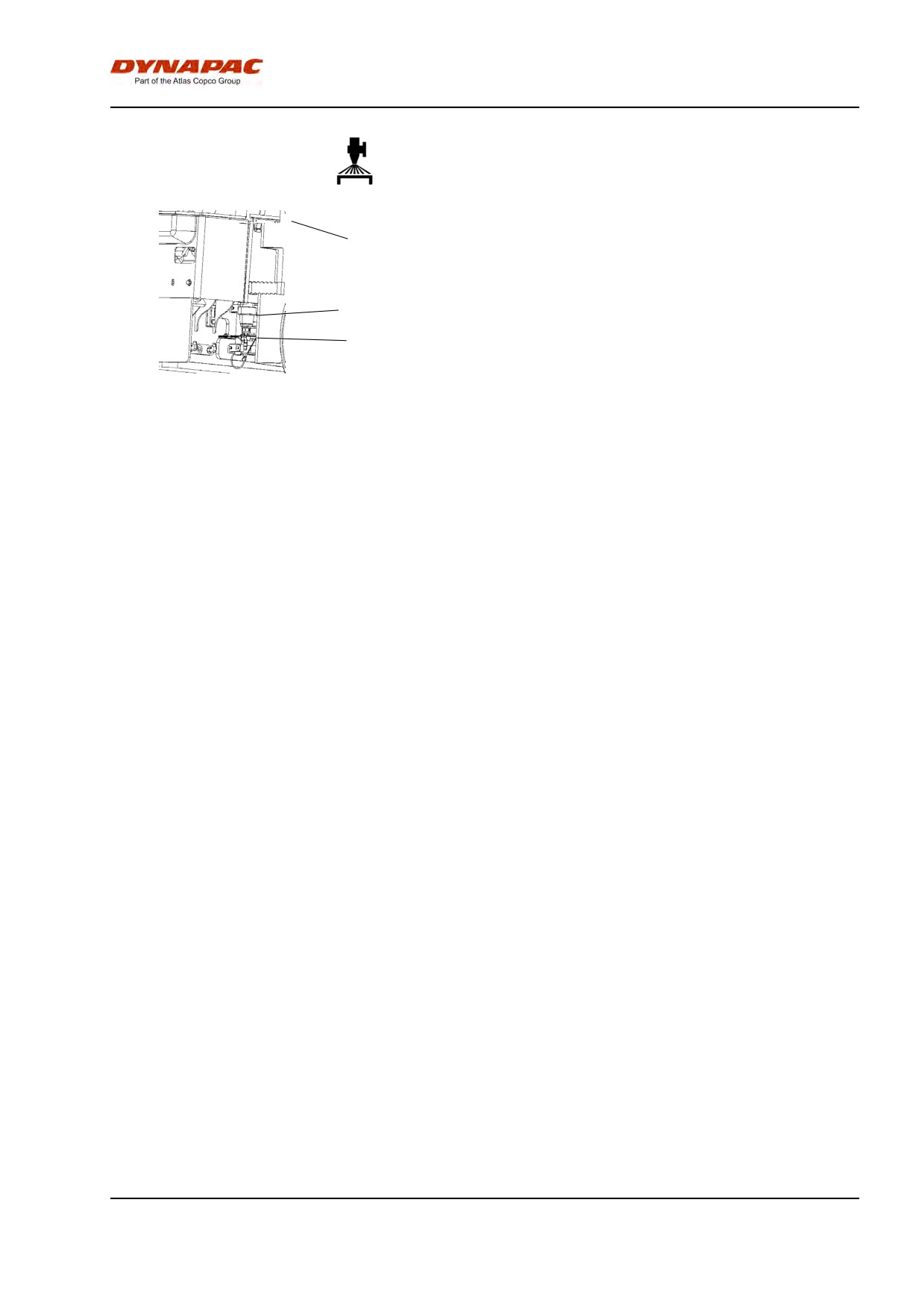
When cleaning the coarse filter (1), open the cock (2)
3
and loosen the filter housing.
Clean the filter and filter housing. Check that the
rubber gasket in the filter housing is intact.
1
After inspecting and carrying out any necessary
cleaning, start the system and check that it works.
2
A drain cock is placed on the left side of the pump
Fig. Pump system
system area. This can be used to drain the tank and
1. Water filter
the pump system.
2. Stop cock
3. Water pump
2012-04-20
69
Maintenance, 10h
2012-04-20
70
Maintenance - 50h
Maintenance - 50h
Park the roller on a level surface.
The engine must be switched off and the
parking brake activated when checking or
adjusting the roller, unless otherwise specified.
Ensue that there is good ventilation (air
extraction) if the engine is run indoors. Risk of
carbon monoxide poisoning.
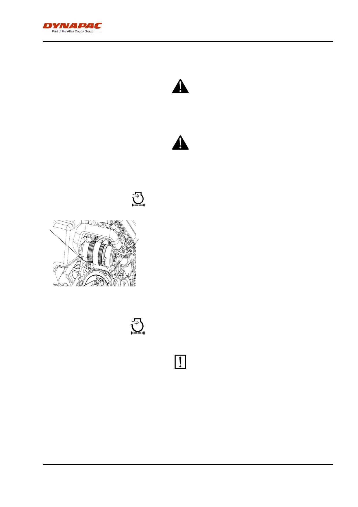
Air cleaner indicator
If the indicator (1) on the air cleaner turns red, replace
1
the main filter (2) on the air cleaner. The dust pouch is
2
emptied by pressing the rubber bellows with your
fingers. Check also that the air hoses are in good
condition.
Clean the air cleaner when operated in extremely
dusty environments.
Fig. Air cleaner
1. Indicator
2. Main filter
Air cleaner
Check - Replacement of main filter
Replace the air cleaner's main filter when the
indicator shows red. The indicator is mounted on
the air cleaner's connecting pipe.
2012-04-20
71
Maintenance - 50h
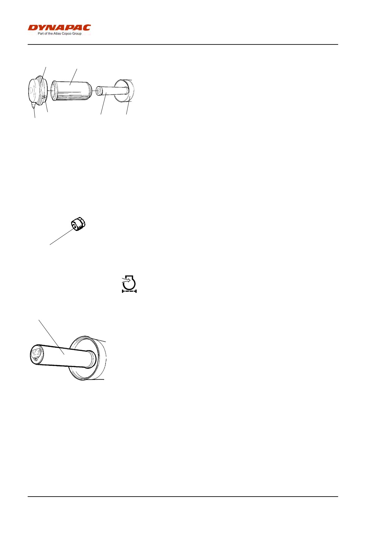
2
3
Release the clips (1), pull off the cover (2), and pull out
the main filter (3).
Do not remove the backup filter (4).
Clean the air cleaner if necessary, see section Air
cleaner - Cleaning.
When replacing the main filter (3), insert a new filter
1
4
5
6
and refit the air cleaner in the reverse order.
Fig. Air cleaner
Check the condition of the dust valve (6); replace if
1. Clips
necessary.
2. Cover
3. Main filter
4. Backup filter
When refitting the cover, make sure that the dust valve
5. Filter housing
is positioned downwards.
6. Dust valve
Air filter indicator - Resetting
The air filter indicator is located on the filter, or in its
immediate vicinity.
The air filter indicator must be reset after replacing the
air filter.
1
Fig. Indicator
Press the "button" (1) on the top of the indicator to
1. Button
reset.
Backup filter - Change
1
Change the backup filter with a new filter after every
third replacement of the main filter.
To change the backup filter (1), pull the old filter out of
its holder, insert a new filter and reassemble the air
cleaner in the reverse order.
Clean the air cleaner if necessary, see section Air
cleaner - Cleaning.
Fig. Air filter
1. Backup filter
2012-04-20
72
Maintenance - 50h
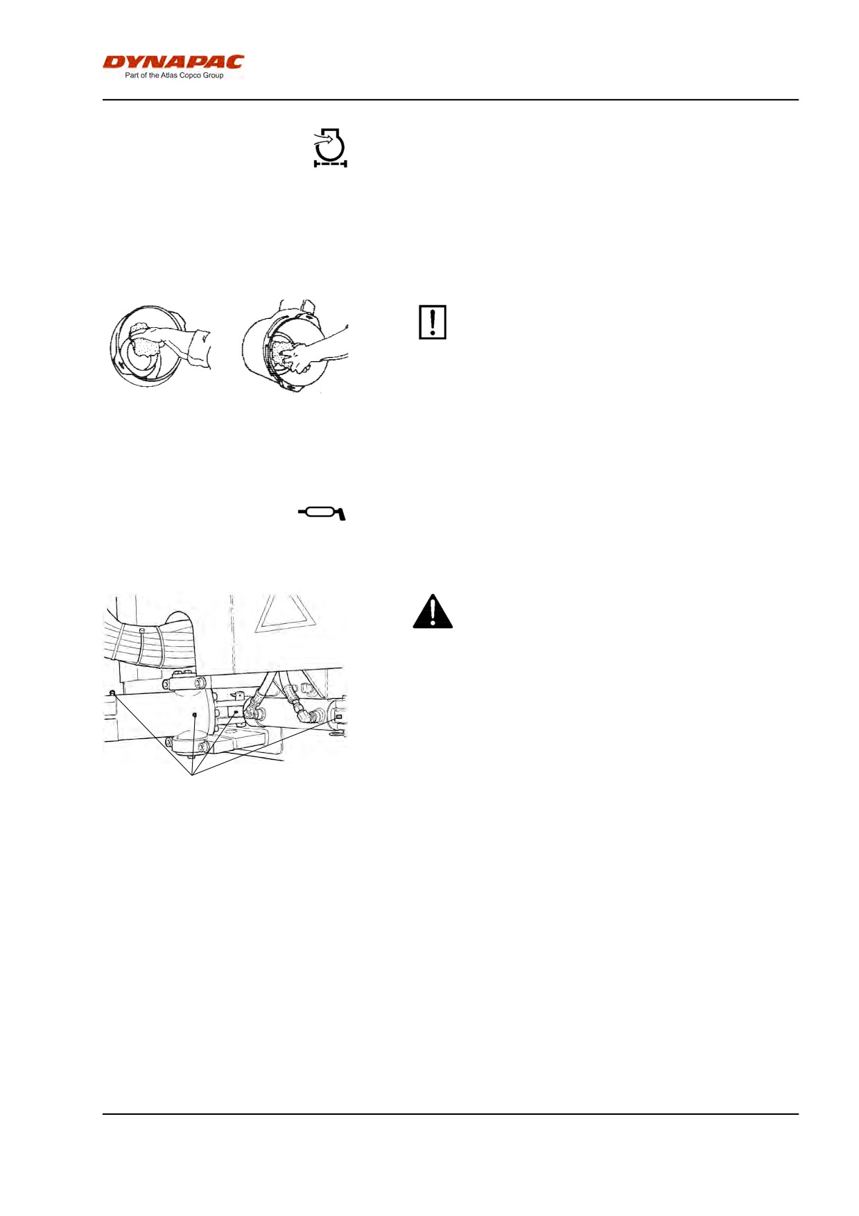
Air cleaner
- Cleaning
Wipe clean the inside of the cover (2) and the filter
housing (5). See the previous illustration.
Wipe clean on both sides of the outlet
pipe.
Wipe also both surfaces for the outlet pipe; see
adjacent figure.
Check that the hose clamps between the filter
housing and the suction hose are tight and that
the hoses are intact. Inspect the entire hose
system, all the way to the engine.
Inner edge of
Outer edge of outlet
outlet pipe.
pipe.
Steering cylinder and steering joint -
Lubrication
Do not allow anyone to remain in the vicinity of the
steering joint when the engine is running. Danger
of crush injury when the steering is operated.
Activate the parking brake before lubricating.
Turn the steering wheel fully to the left. All four grease
nipples (1) can now be accessed from the right side of
1
the machine.
Fig. Main filter
Wipe the grease nipples (1). Grease each nipple with
1. Grease nipples
five strokes of the hand-operated grease gun. Make
sure that grease penetrates into the bearing. If grease
does not penetrate the bearings, it may be necessary
to relieve the articulation joint with a jack while
repeating the greasing process.
2012-04-20
73
Maintenance - 50h
2012-04-20
74
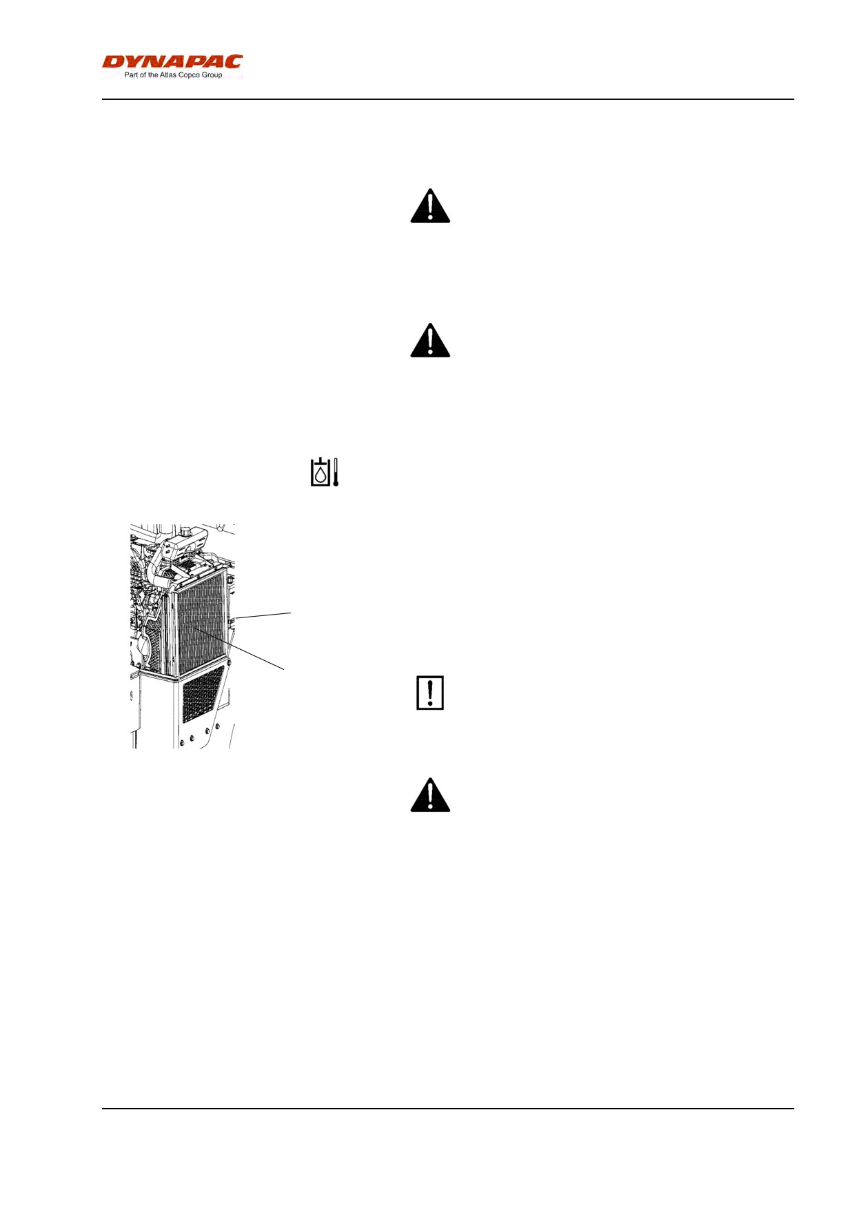
Maintenance - 250h
Maintenance - 250h
Park the roller on a level surface.
The engine must be switched off and the
parking brake activated when checking or
adjusting the roller, unless otherwise specified.
Ensue that there is good ventilation (air
extraction) if the engine is run indoors. Risk of
carbon monoxide poisoning.
Coolers
Checking - Cleaning
Make sure that the air flow through the coolers (1) and
(2) is unobstructed. Dirty coolers are blown clean with
compressed air or washed clean using a
high-pressure water cleaner.
1
Blow air or direct water through the cooler in the
opposite direction to that of the cooling air.
2
Take care when using a high-pressure water jet.
Do not hold the nozzle too near the cooler.
Fig. Engine compartment
1. Water cooler
Wear protective goggles when working with
2. Hydraulic fluid cooler
compressed air or high-pressure water jets.
2012-04-20
75
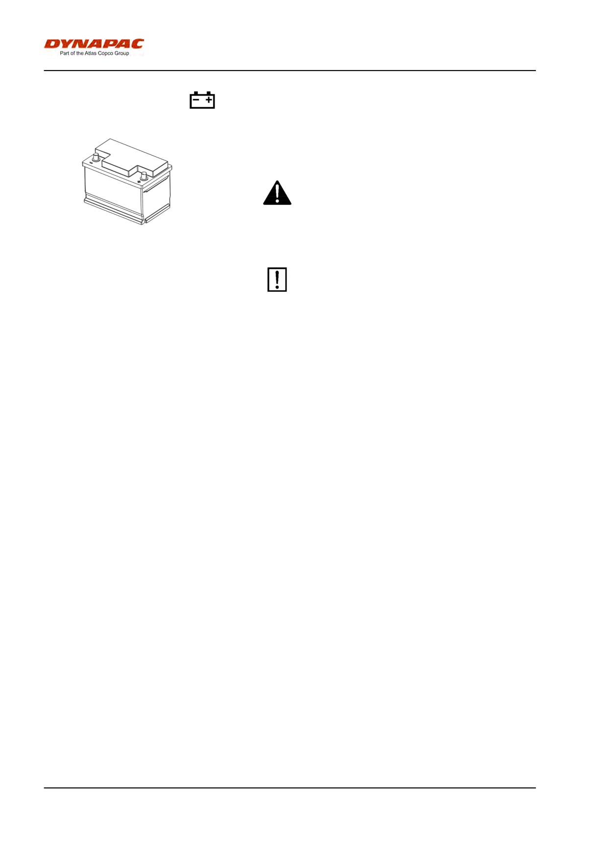
Maintenance - 250h
Battery
- Check condition
The battery is sealed and maintenance-free.
Make sure there is no open flame in the vicinity
when checking the electrolyte level. Explosive gas
is formed when the alternator charges the battery.
Fig. Battery
When disconnecting the battery, always
disconnect the negative cable first. When
connecting the battery, always connect the
positive cable first.
The cable shoes should be clean and well-tightened.
Corroded cable shoes should be cleaned and greased
with acid-free Vaseline.
Wipe the top of the battery.
2012-04-20
76
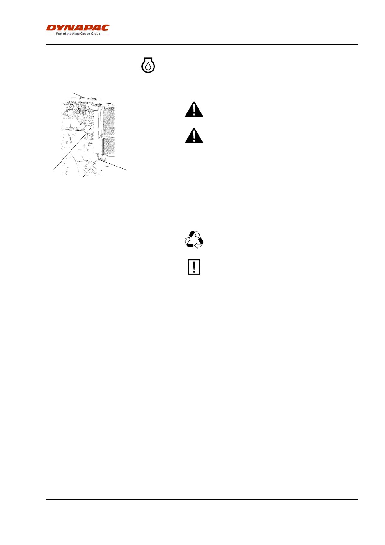
Maintenance - 250h
Engine oil and oil filter - Change
3
Run the engine until it is warm before draining the oil .
Switch off the engine and push in the emergency
brake button.
Take great care when draining fluids and oils.
Wear protective gloves and goggles.
4
1
2
Fig. Engine compartment right side
Set a container which can hold at least 8 liters (2 gal)
1. Drain hose
under the drain plug (2).
2. Drain plug
3. Filler cap
Undo the oil filler cap (3), and undo the drain plug (2)
4. Oil filter
in the end of the drain hose (1). Let all the engine oil
flow out.
Deliver the drained oil to special waste handling.
Refer to the engine manual for detailed
instructions when changing oil and filters.
Remove the oil filter (4) and fit a new filter.
Collect any spillage.
Fit the drain plug (2) to the end of the hose.
Fill with fresh engine oil. See under the heading
lubricants, for the correct oil grade. Fit the filler cap (3)
and check that the oil level is correct using the dipstick.
Start the engine and allow it to idle for a few minutes.
During this time, check around the oil filter and drain
plug for leaks.
Switch off the engine, wait for a minute or so and then
check the oil level. Top up with more oil if necessary.
2012-04-20
77
Maintenance - 250h
2012-04-20
78
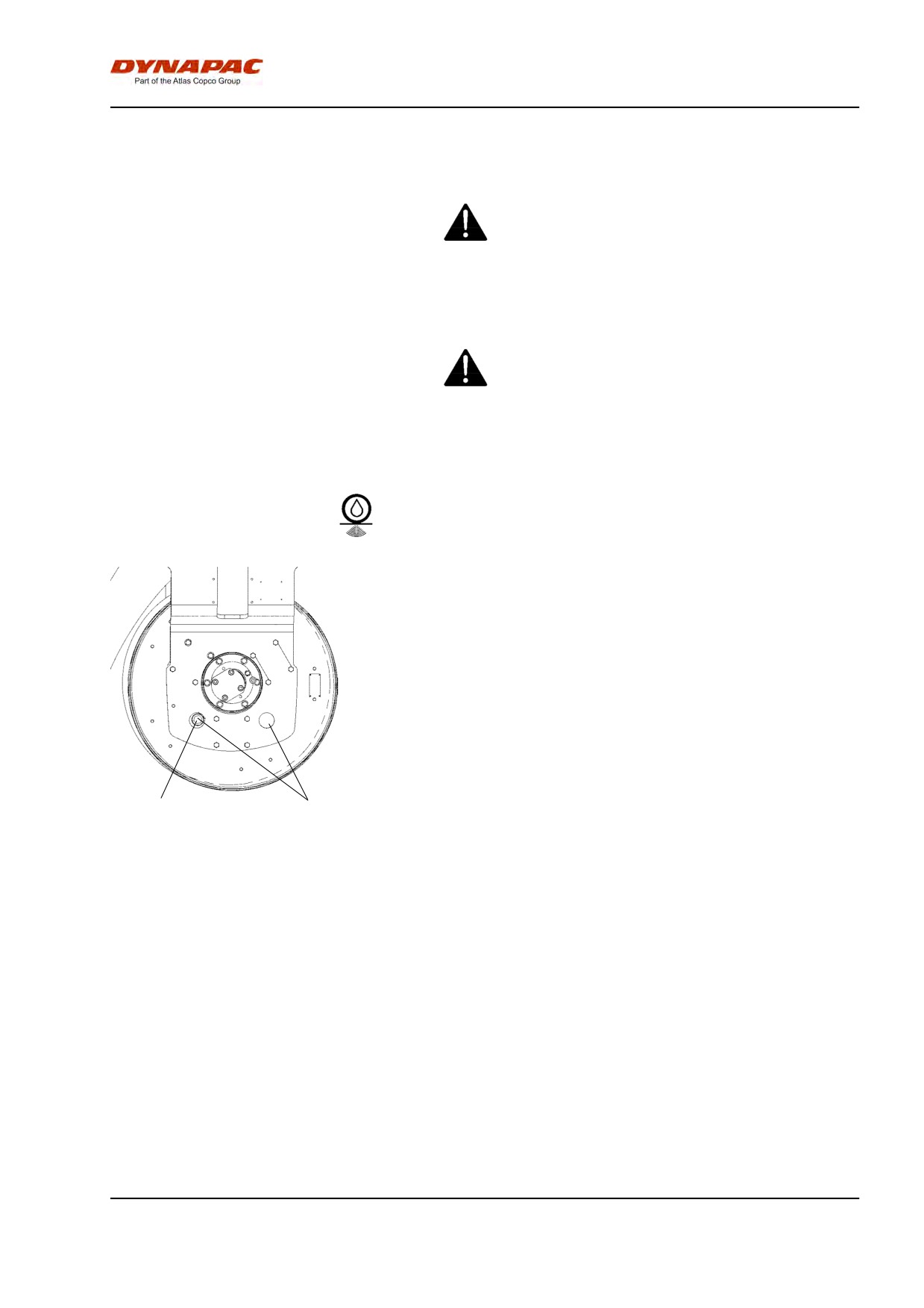
Maintenance - 500h
Maintenance - 500h
Park the roller on a level surface.
The engine must be switched off and the
parking brake activated when checking or
adjusting the roller, unless otherwise specified.
Ensue that there is good ventilation (air
extraction) if the engine is run indoors. Risk of
carbon monoxide poisoning.
Drum - oil level
Inspection - filling
Run the roller slowly until the oil plug (1) is opposite
one of the inspection holes (2).
Unscrew the plug and check that the oil level reaches
up to the bottom of the hole. Top up with new oil if
necessary. Use oil as per the lubricant specification.
Clean the magnetic oil plug (1) from any metallic
residue, and refit the plug.
1
2
Fig. Drum, vibration side
1. Oil plug
2. Inspection hole
2012-04-20
79
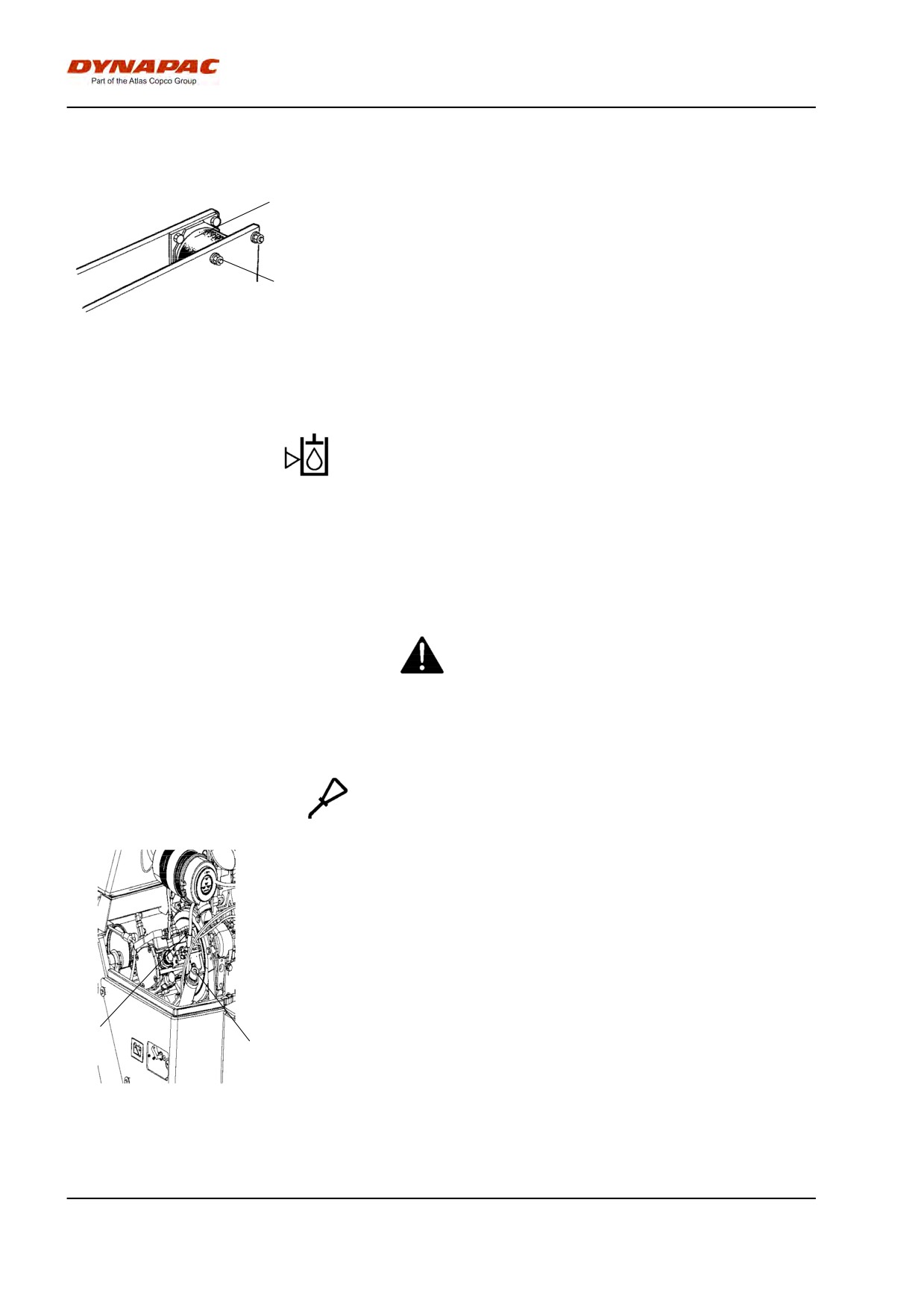
Maintenance - 500h
Rubber elements and attachment screws
Check
1
Check all rubber elements (1). Replace all elements
where more than 25% of the elements on one side of
the drum have cracks deeper than 10-15 mm (0.4-0.6
in).
2
Check using a knife blade or pointed object.
Check also that the attachment screws (2) are
Fig. Drum, vibration side
tightened.
1. Rubber element
2. Attachment screws
Hydraulic reservoir cap - Check
Screw off the tank cap and check that it is not clogged.
Air must have unobstructed passage through the cap
in both directions.
If clogged in either direction, clean with a little diesel
oil and blow with compressed air until free passage is
assured or replace the cap with a new one.
Wear protective goggles when working with
compressed air.
Controls - Lubrication
Lubricate the forward/reverse lever in the engine
compartment with a few drops of oil.
If the lever gets stiff after a prolonged period of use,
remove the cover and lever and lubricate.
1
2
Fig. Engine compartment
1. Forward/Reverse lever
2. Hydraulic reservoir cap
2012-04-20
80
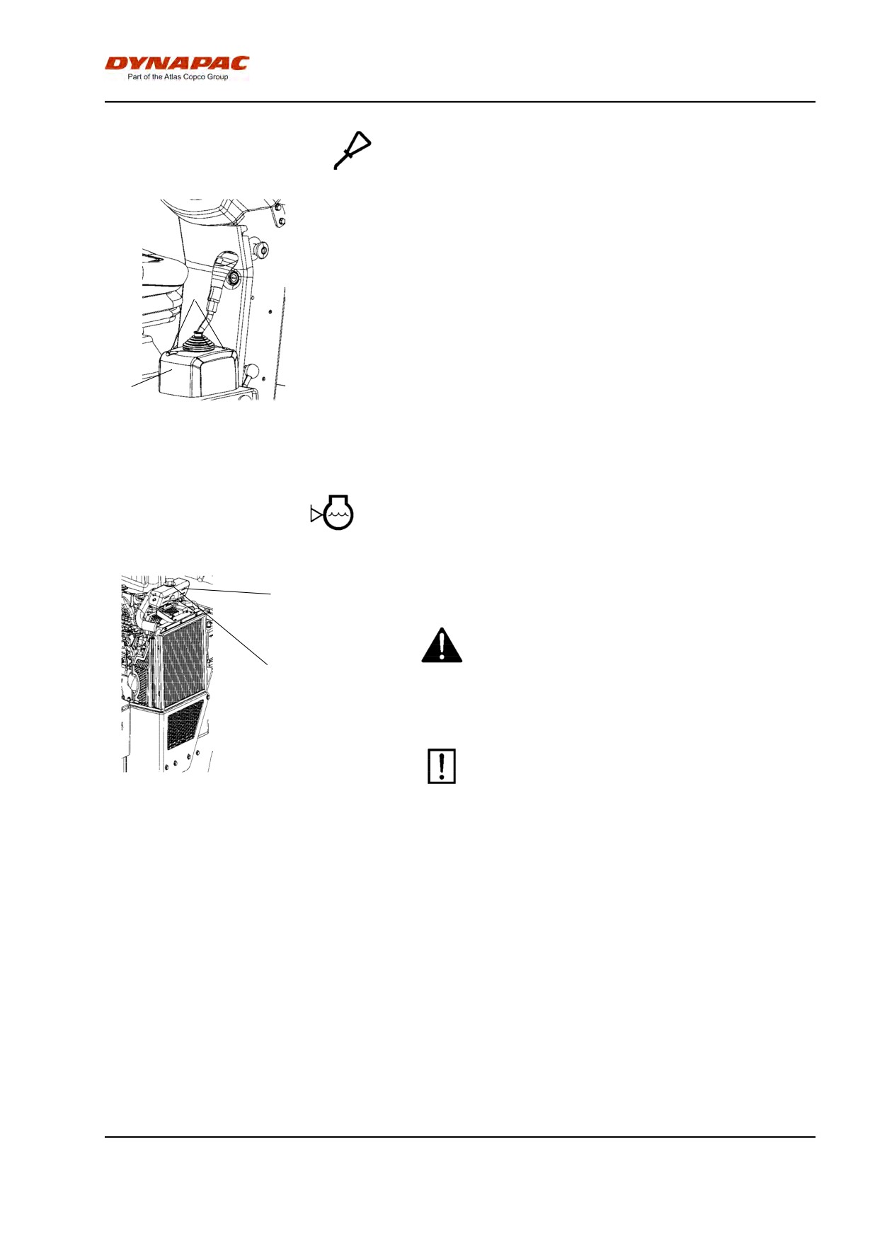
Maintenance - 500h
Controls - Lubrication
Lubricate the forward/reverse lever mechanism.
Remove the cover (1) by loosening the screws (2) on
the top, and lubricate the mechanism under the cover
with oil.
2
1
Fig. Driver seat
1. Forward/Reverse lever
2. Attachment screws
Check - Coolant system
Check that all hoses/hose connectors are intact and
2
tight. Fill with coolant as specified in the lubricants
specification.
Take great care when opening the radiator cap
while the engine is hot. Wear protective gloves and
goggles.
1
Also check the freezing point. Change the coolant
every other year.
Figure. Cooling water container
1. Filler cap
2. Level marking
2012-04-20
81
Maintenance - 500h
2012-04-20
82
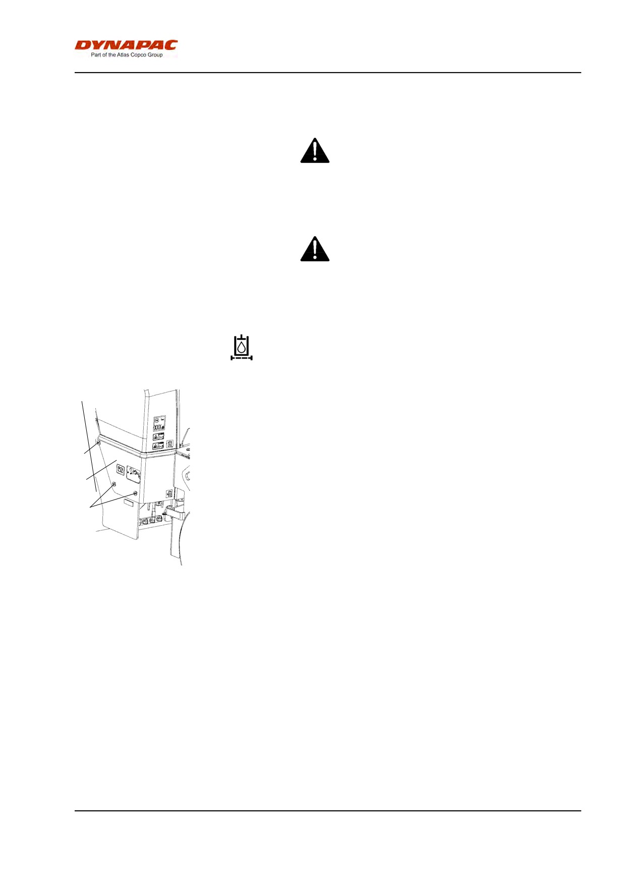
Maintenance - 1000h
Maintenance - 1000h
Park the roller on a level surface.
The engine must be switched off and the
parking brake activated when checking or
adjusting the roller, unless otherwise specified.
Ensue that there is good ventilation (air
extraction) if the engine is run indoors. Risk of
carbon monoxide poisoning.
Replacing the hydraulic oil filter
Unscrew the retaining screws (1) on each side of the
roller.
Remove the protective cover (2).
1
2
1
Fig. Engine compartment
1. Retaining screws
2. Protective cover
2012-04-20
83
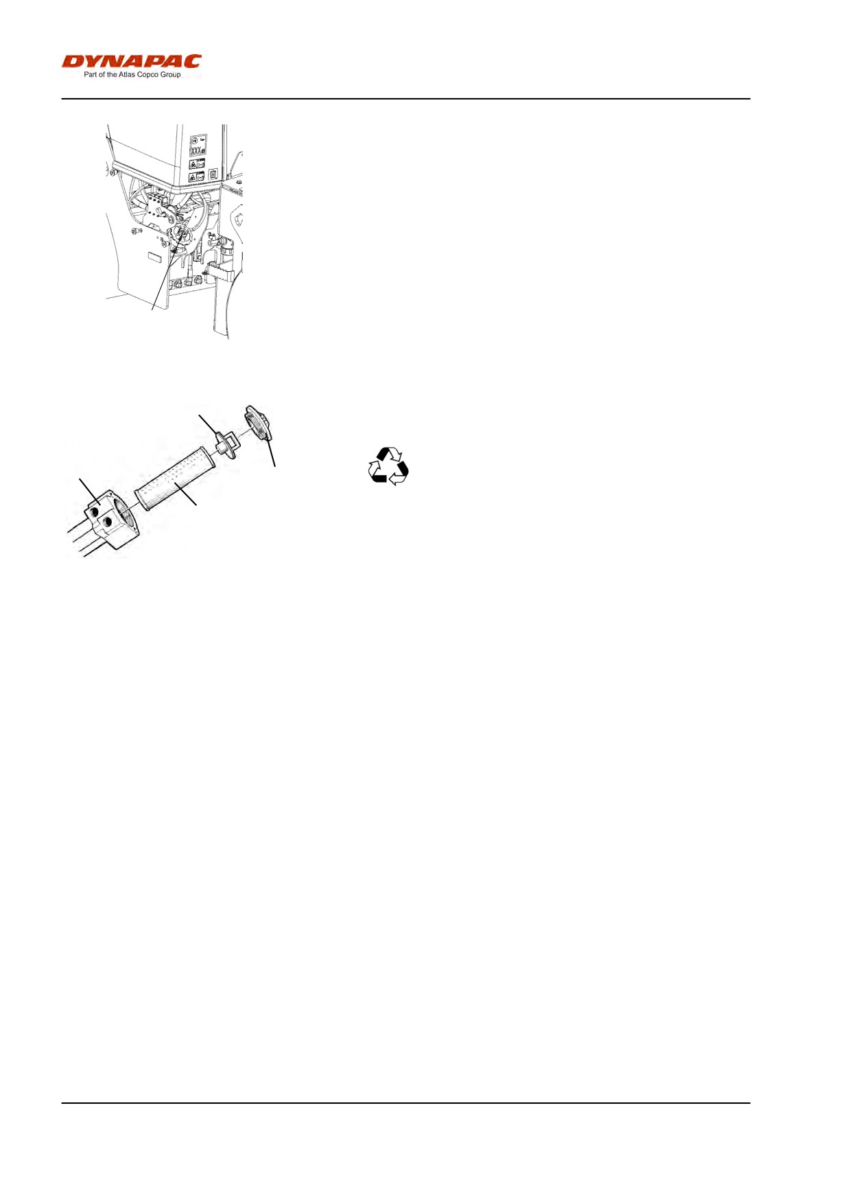
Maintenance - 1000h
Loosen the red cap (3) and pull up the filter insert (4).
Refit the red cap temporarily to prevent dust and dirt
getting into the tank.
3
Fig. Hydraulic oil filter
3. Cap
5
Release the filter insert (4) from the handle (5).
Remove the filter (4) and hand in to an
6
environment-friendly waste disposal station. This
3
is a disposable filter and cannot be cleaned.
4
Fig. Hydraulic oil filter
3. Cap
Mount the new insert on the handle, refit the unit into
4. Filter insert
the filter holder (6), and refit the red cover.
5. Handle
6. Filter holder
Start the engine and allow it to run at full revs for 30
seconds. Check that the filter cap (3) is tight.
2012-04-20
84
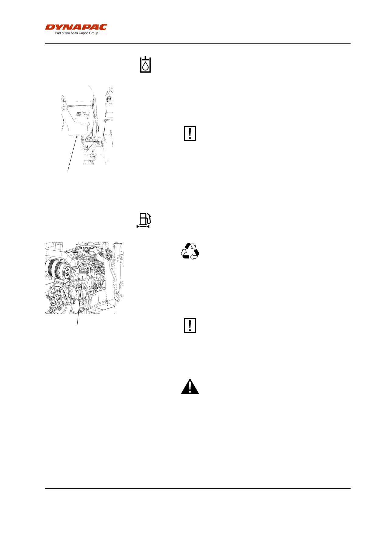
Maintenance - 1000h
Hydraulic fluid reservoir - Draining
Condensate in the hydraulic tank is drained via the
plug (1). This should be done when the roller has
stood still for some time, e.g. during the night.
Be very careful during draining. Do not drop the
plug or else all the hydraulic fluid will flow out.
Drain as follows:
1
Fig. Left frame side
Place a container under the plug (1). Loosen and allow
1. Drain plug
any condensate to run out. Tighten the plug.
Replacing the fuel filter
Place a container underneath to collect fuel that
runs out when the filter is released.
Screw off the fuel filter (1). The filter is of the
disposable type and cannot be cleaned. Han in to
environment-friendly station.
Refer to the engine manual for detailed
1
instructions when replacing the fuel filter.
Fig. Engine compartment
1. Fuel filter
Start the engine and check that the fuel filter is tight.
Ensure good ventilation (air extraction) if the
diesel engine is run indoors. Risk of carbon
monoxide poisoning.
2012-04-20
85
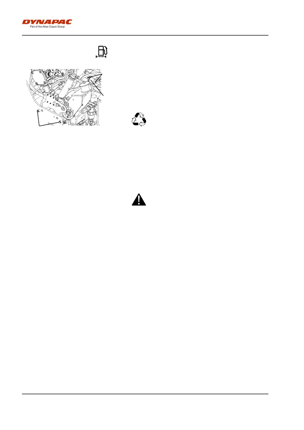
Maintenance - 1000h
Replacing the pre-filter
2
Activate the parking brake.
Switch off the engine and remove the plate on the left
side of the frame (at battery disconnector) by releasing
the three bolts (3).
1
Release the hose clamps (2) with a screwdriver.
Place a container underneath to collect fuel that
runs out when the filter is released.
3
Remove the pre-filter (1) and hand in to
Fig. Engine compartment
environment-friendly station. This is a disposable filter
1. Pre-filter
and cannot be cleaned.
2. Hose clamps
3. Bolts
Fit a new pre-filter and tighten the hose clamps.
Start the engine and check that the pre-filter is tight.
Ensure good ventilation (air extraction) if the
diesel engine is run indoors. Risk of carbon
monoxide poisoning.
2012-04-20
86
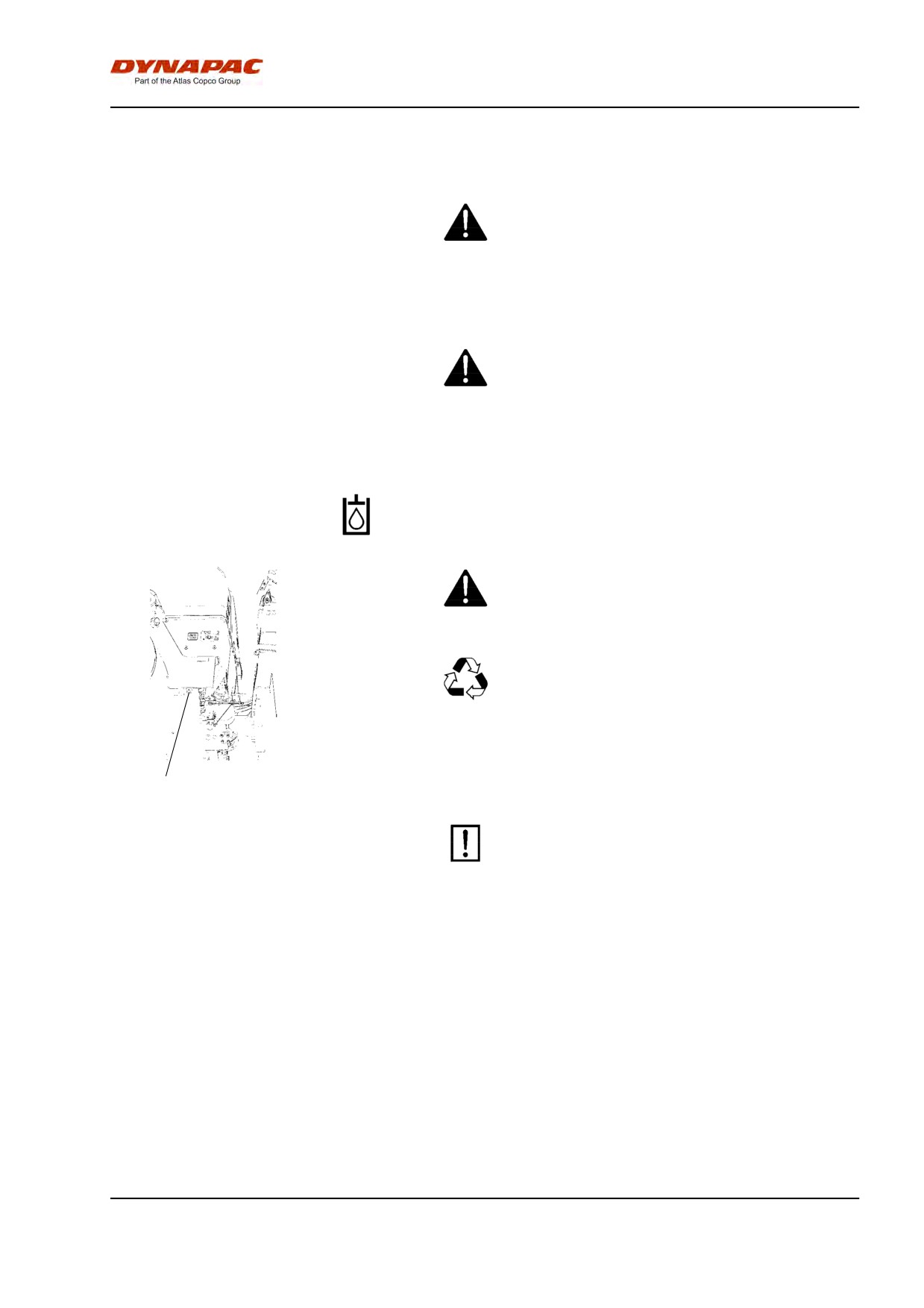
Maintenance - 2000h
Maintenance - 2000h
Park the roller on a level surface.
The engine must be switched off and the
parking brake activated when checking or
adjusting the roller, unless otherwise specified.
Ensue that there is good ventilation (air
extraction) if the engine is run indoors. Risk of
carbon monoxide poisoning.
Hydraulic tank - Changing the fluid
Risk of burn injuries when draining hot oil. Protect
your hands.
Place a container under the plug. It should hold at
least 50 liters. Save the oil and dispose of it in an
approved manner.
Unscrew the drain plug (1) and allow all the oil to run
out. Wipe and replace the drain plug.
1
Fig. Left frame side
1. Drain plug
Fill with fresh hydraulic fluid of the grade
indicated in the Lubricant specification.
Replace the hydraulic fluid filter. See under the
heading 'Every 1000 hours of operation'.
Start the diesel engine and run the various hydraulic
functions. Check the fluid level in the tank, and top up
if necessary.
2012-04-20
87
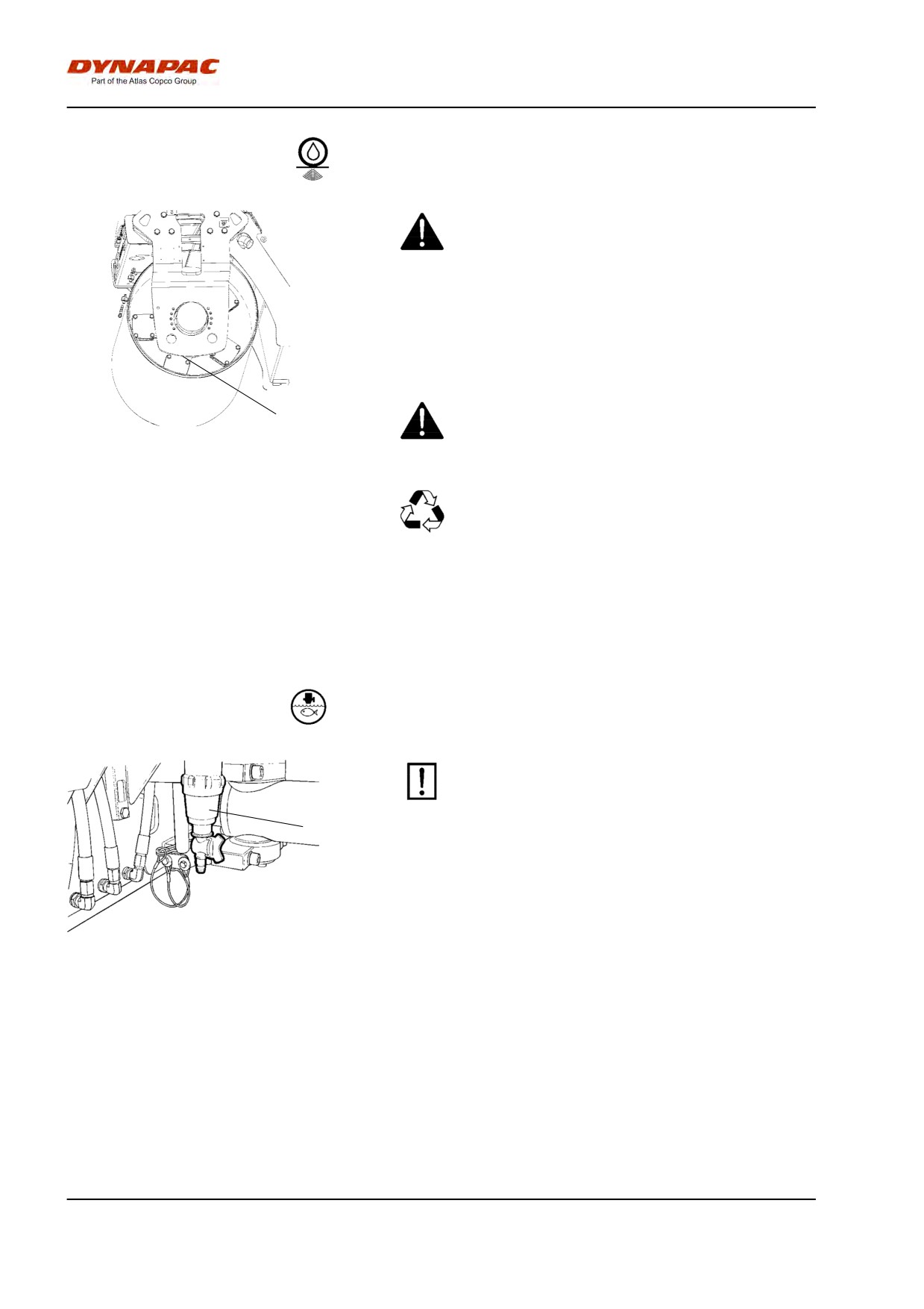
Maintenance - 2000h
Drum - Oil change
Take great care when draining the fluid. Wear
protective gloves and goggles.
Place the roller on a level surface and drive it slowly
until the drain plug (1) is straight down.
Switch off the engine and activate the parking
1
brake.
Fig. Drum, vibration side
1. Drain plug
Place a receptacle that will hold at least 7 liters
(7.4 quarts) under the plug. Collect the oil and
dispose of it properly.
Remove the plug and allow all the oil to run out. See
under the heading 'Every 500 hours of operation' for
filling oil.
Water tank - Draining
Remember that there is a risk of freezing during
the winter. Empty the tank, pump and lines.
1
The easiest way to empty the water tank is to open the
drain cock on the water filter (1). (There is also a drain
plug under the water tank).
Fig. Pump system
1. Water filter
2012-04-20
88
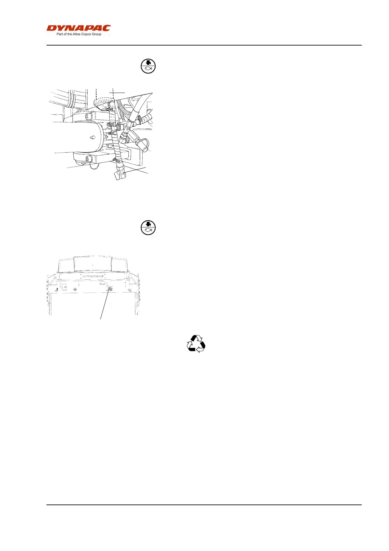
Maintenance - 2000h
Water pump - Draining
1
The water pump (1) is emptied by opening the drain
cock (2).
2
Fig. Pump system
1. Water pump
2. Drain cock
Water tank - Cleaning
Clean the tanks with water and a suitable detergent for
plastic surfaces.
Refit the filter housing or the drain plug (1). Fill with
water and check for leaks.
1
Fig. Water tank
The water tanks are made of plastic
1. Drain plug
(polyethylene) and are recyclable.
2012-04-20
89
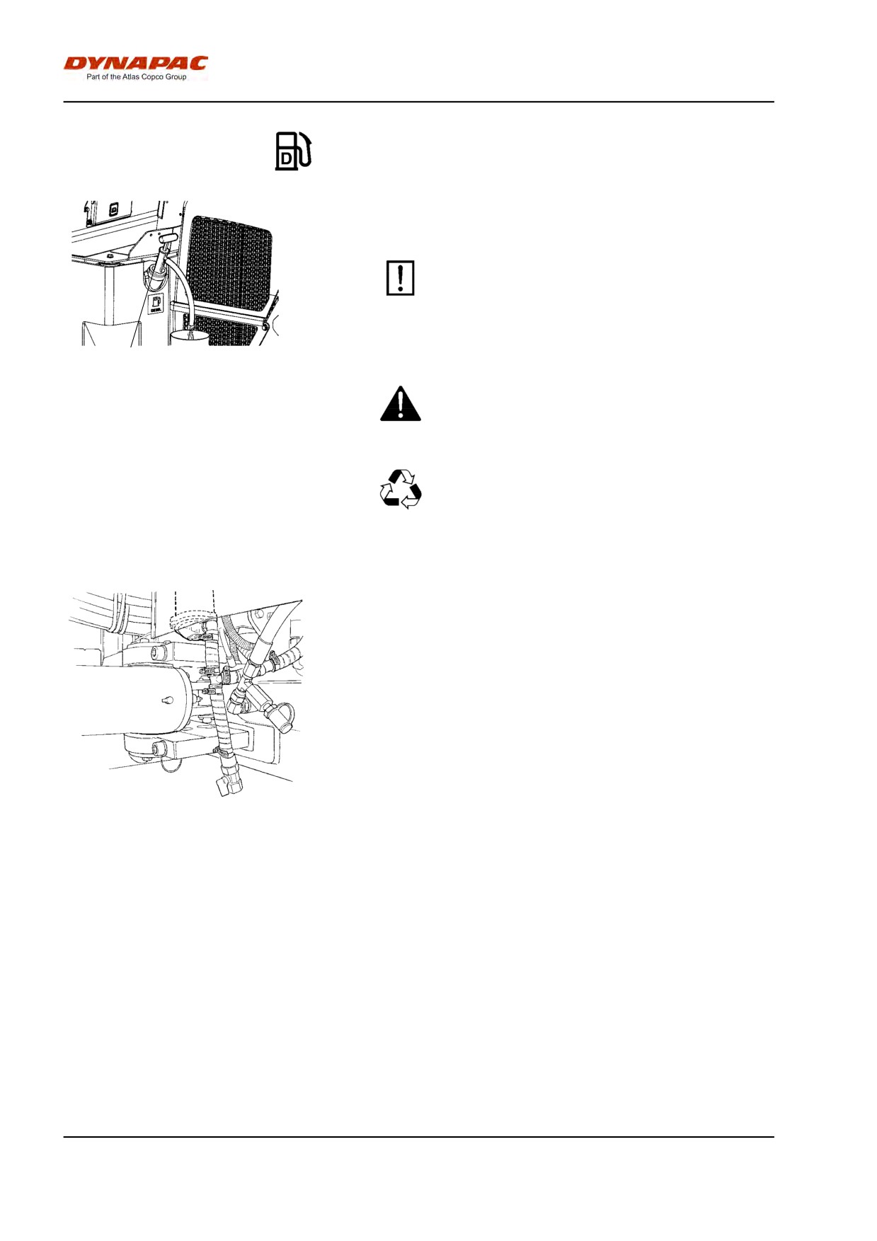
Maintenance - 2000h
Fuel tank - Cleaning
It is easiest to clean the tank when it is almost empty.
Pump out any bottom sediment using a suitable
pump, such as an oil drain pump. Save the oil in
a container and dispose of it in an approved
manner.
1
Fig. Fuel tank
Keep in mind fire risk when handling fuel.
1. Fuel tank
The fuel tank is made of plastic (polyethylene)
and is recyclable.
Steering joint - Check
Check the steering joint for any damage or cracks.
Check and tighten any loose bolts.
Check also for any stiffness and play.
Fig. Steering joint
2012-04-20
90
Dynapac Compaction Equipment AB
Box 504, SE-371 23 Karlskrona, Sweden
Dynapac Compaction Equipment AB
Box 504, SE-371 23 Karlskrona, Sweden