DYNAPAC Vibratory roller CA362 Engine Cummins QSB 6.7C. Operation & Maintenance (2010)
Instructions manual
Driving & Maintenance
Vibratory roller
CA362
Engine
Cummins QSB 6.7C
Serial number
*72X11155*-*72X11170*
CA362 is one of Dynapac's medium-heavy soil compaction rollers. It is
available in a D (smooth drum) and PD (padfoot) version. The main
applications for the PD version are on cohesive material and weathered
stone material.
All types of base courses and subbase courses can be compacted deeper
and the interchangeable drums, D to PD, and vice versa, facilitate even
greater variety in the range of application.
The cab and safety-related accessories are described in this manual.
Other accessories, such as compaction meter, tachograph and field
computer, are described in separate instructions.
Reservation for changes
Printed in Sweden
Table of Contents
Introduction
1
Safety - General instructions
3
Safety - when operating
5
Safety (Optional)
7
Special instructions
9
Technical specifications - Noise/Vibrations/Electrical
13
Technical specifications - Dimensions
15
Technical specifications - Weights and volumes
17
Technical specifications - Working capacity
19
Technical specifications - General
21
Machine plate - Identification
25
Machine description - Instruments/Controls
31
Machine description - Electrical system
39
Operation - Starting
45
Operation - Driving
51
Operation - Vibration
55
Operating - Stopping
57
Long-term parking
59
Miscellaneous
61
Operating instructions - Summary
67
Maintenance - Lubricants and symbols
69
Maintenance - Maintenance schedule
71
Maintenance - 10h
77
Maintenance - 50h
83
Maintenance - 250h
89
Maintenance - 500h
95
Maintenance - 1000h
99
Maintenance - 2000h
105
Introduction
Introduction
Warning symbols
WARNING ! Marks a danger or a hazardous
procedure that can result in life threatening or
serious injury if the warning is ignored.
CAUTION ! Marks a danger or hazardous
procedure that can result in damage to the
machine or property if the warning is ignored.
Safety information
The safety manual supplied with the machine
must be read by all roller operators. Always
follow the safety instructions. Do not remove
the manual from the machine.
We recommend that the operator reads the
safety instructions in this manual carefully.
Always follow the safety instructions. Ensure
that this manual is always easily accessible.
Read the entire manual before starting the
machine and before carrying out any
maintenance.
Ensure good ventilation (extraction of air by fan)
where the engine is run indoors.
CALIFORNIA
Proposition 65 Warning
Diesel engine exhaust and some of its constituents are
known to the State of California to cause cancer, birth
defects, and other reproductive harm.
General
This manual contains instructions for machine
operation and maintenance.
1
Introduction
The machine must be correctly maintained for
maximal performance.
The machine should be kept clean so that any
leakages, loose bolts and loose connections are
discovered at as early a point in time as possible.
Inspect the machine every day, before starting.
Inspect the entire machine so that any leakages or
other faults are detected.
Check the ground under the machine. Leakages are
more easily detected on the ground than on the
machine itself.
THINK ENVIRONMENT ! Do not release oil,
fuel and other environmentally hazardous
substances into the environment. Always send
used filters, drain oil and fuel remnants to
environmentally correct disposal.
This manual contains instructions for periodic
maintenance normally carried out by the operator.
Additional instructions for the engine can be
found in the manufactuer's engine manual.
2
Safety - General instructions
Safety - General instructions
(Also read the safety manual)
1.
The operator must be familiar with the contents of the OPERATION section
before starting the roller.
2.
Ensure that all instructions in the MAINTENANCE section are followed.
3.
Only trained and/or experienced operators are to operate the roller.
Passengers are not permitted on the roller. Remain seated at all times when
operating the roller.
4.
Never use the roller if it is in need of adjustment or repair.
5.
Only mount and dismount the roller when it is stationary. Use the intended
grips and rails. Always use the three-point grip (both feet and one hand, or
one foot and both hands) when mounting or dismounting the machine.
Never jump down from the machine.
6.
The ROPS (Roll Over Protective Structure) should always be used when the
machine is operated on unsafe ground.
7.
Drive slowly in sharp bends.
8.
Avoid driving across slopes. Drive straight up or straight down the slope.
9.
When driving close to edges, ditches or holes, make sure that at least 2/3 of
the drum width is on previously compacted material (solid surface).
10.
Make sure that there are no obstacles in the direction of travel, on the
ground, in front of or behind the roller, or overhead.
11.
Drive particularly carefully on uneven ground.
12.
Use the safety equipment provided. The seat belt must be worn on machines
fitted with ROPS.
13.
Keep the roller clean. Clean any dirt or grease that accumulates on the
operator platform immediately. Keep all signs and decals clean and legible.
14.
Safety measures before refueling:
- Shut off the engine
- Do not smoke
- No naked flame in the vicinity of the machine
- Ground the filling device nozzle to the tank to avoid sparks
15.
Before repairs or service:
- Chock the drums/wheels and under the strike-off blade.
- Lock the articulation if necessary
3
Safety - General instructions
16. Hearing protection is recommended if the noise level exceeds 85 dB(A). The
noise level can vary depending on the equipment on the machine and the
surface the machine is being used on.
17. Do not make any changes or modifications to the roller that could affect
safety. Changes are only to be made after written approval has been given
by Dynapac.
18. Avoid using the roller before the hydraulic fluid has reached its normal
working temperature. Braking distances can be longer than normal when the
fluid is cold. See instructions in the STOP section.
19. For your own protection always wear:
- helmet
- working boots with steel toecaps
- ear protectors
- reflecting clothing/high visibility jacket
- working gloves
4
Safety - when operating
Safety - when operating
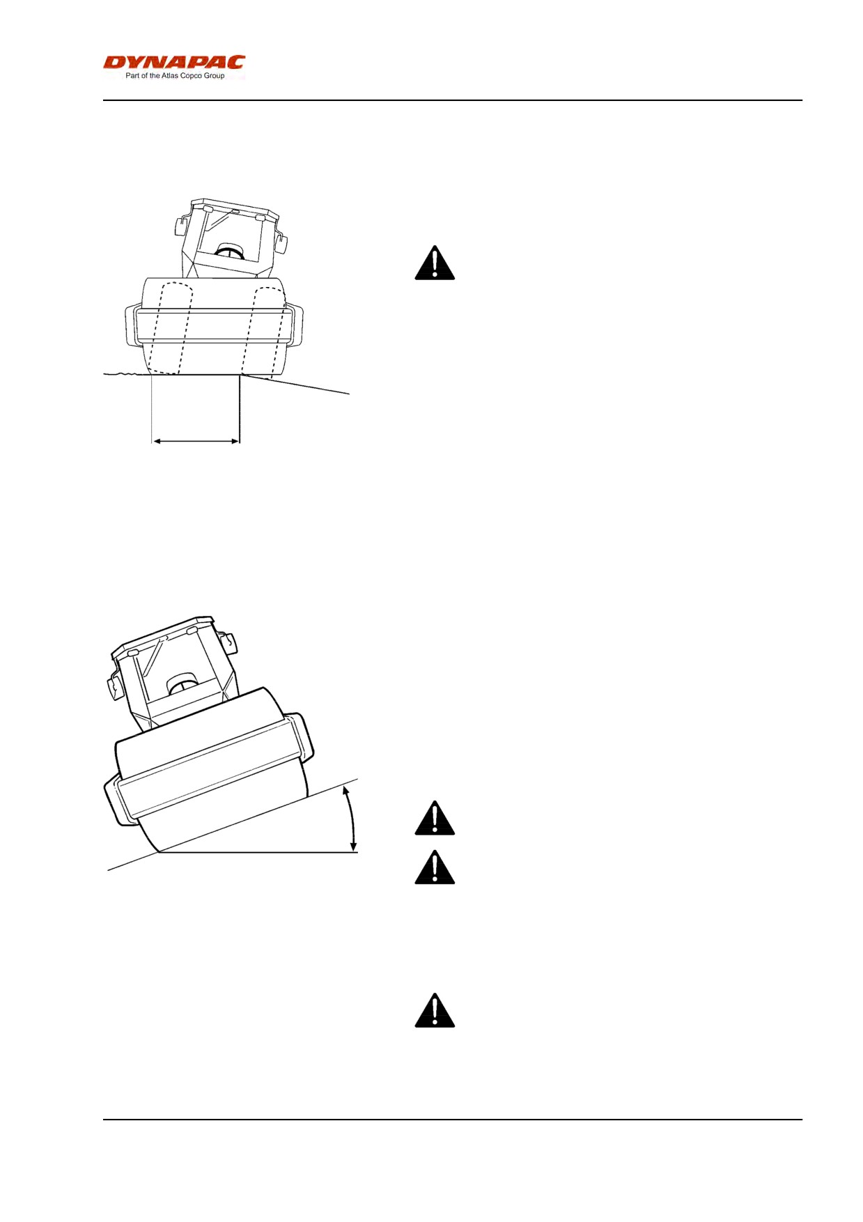
Driving near edges
When driving near an edge, minimum 2/3 of the drum
width must be on solid ground.
Keep in mind that the machine's center of gravity
moves outwards when steering. For example, the
center of gravity moves to the right when you
steer to the left.
Minimum
2/3
Fig. Position of drum when driving near
an edge
Slopes
This angle has been measured on a hard, flat surface
with the machine stationary.
The steering angle was zero, the vibration was
switched OFF and all tanks were full.
Always take into consideration that loose ground,
steering the machine, vibration on, machine speed
across the ground and raising the center of gravity can
all cause the machine to topple at smaller slope
angles than those specified here.
To exit the cab in an emergency, release the
Max 20° or 36%
hammer on the rear right post and break the
rear window.
It is recommended that ROPS (Roll Over
Protective Structure) or a ROPS-approved cab is
Fig. Operating on slopes
always used when driving on slopes or unsafe
ground. Always wear a safety belt.
Where possible, avoid driving across slopes.
Drive instead straight up and down sloping
ground.
5
Safety - when operating
6
Safety (Optional)
Safety (Optional)
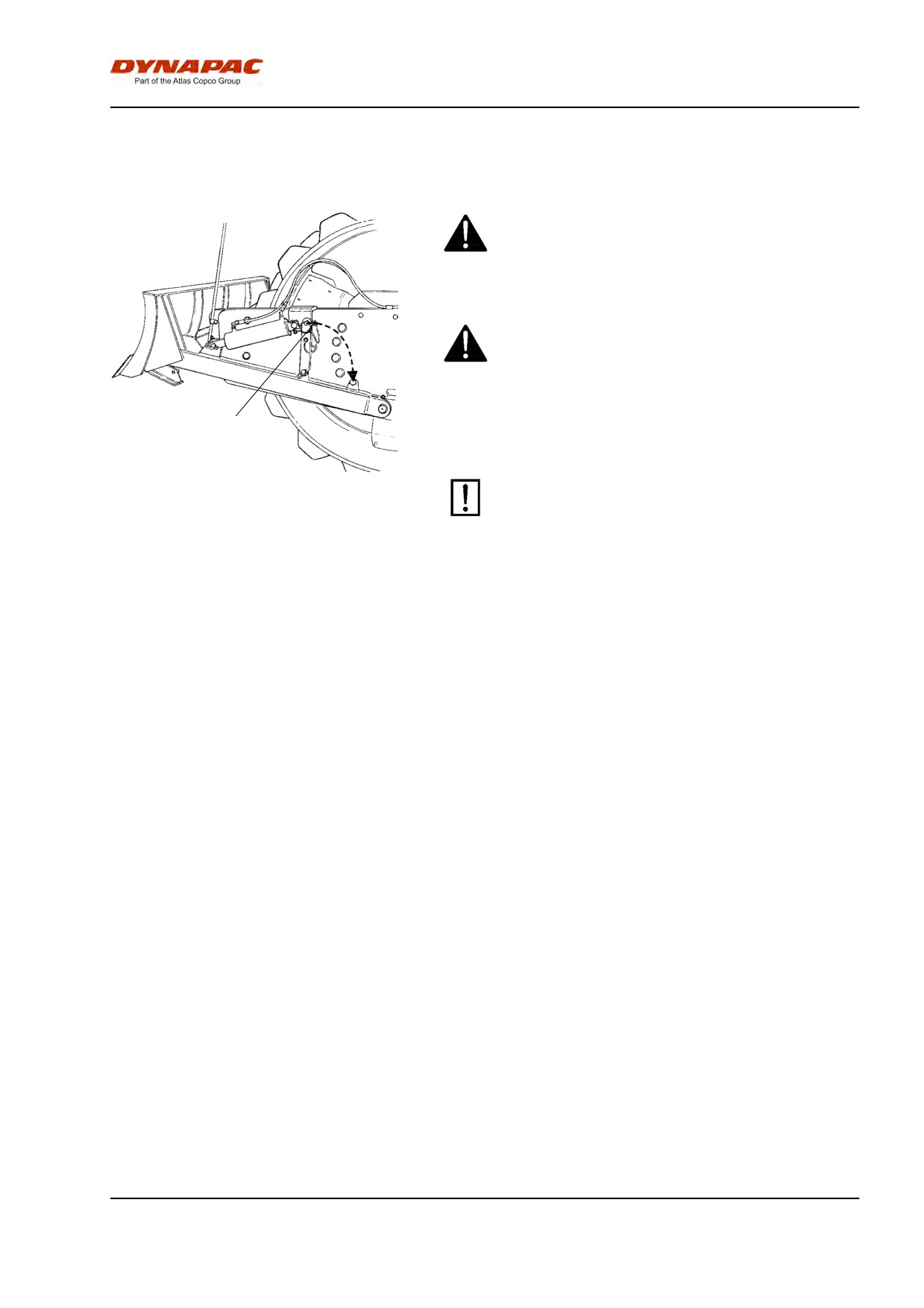
Strike-off blade
The operator must make sure that nobody is in
the area of operation while the machine is in
use.
Ensure always that the strike-off blade is
secured by the locking pin (1) when driving
with the blade in its raised position. Always
lower the blade to the ground before leaving or
parking the roller.
1
Fig.Strike-off blade
The strike-off blade must be retracted to the
1. Locking pin
transport position (1) at the end of each
working period.
7
Safety (Optional)
Air conditioning
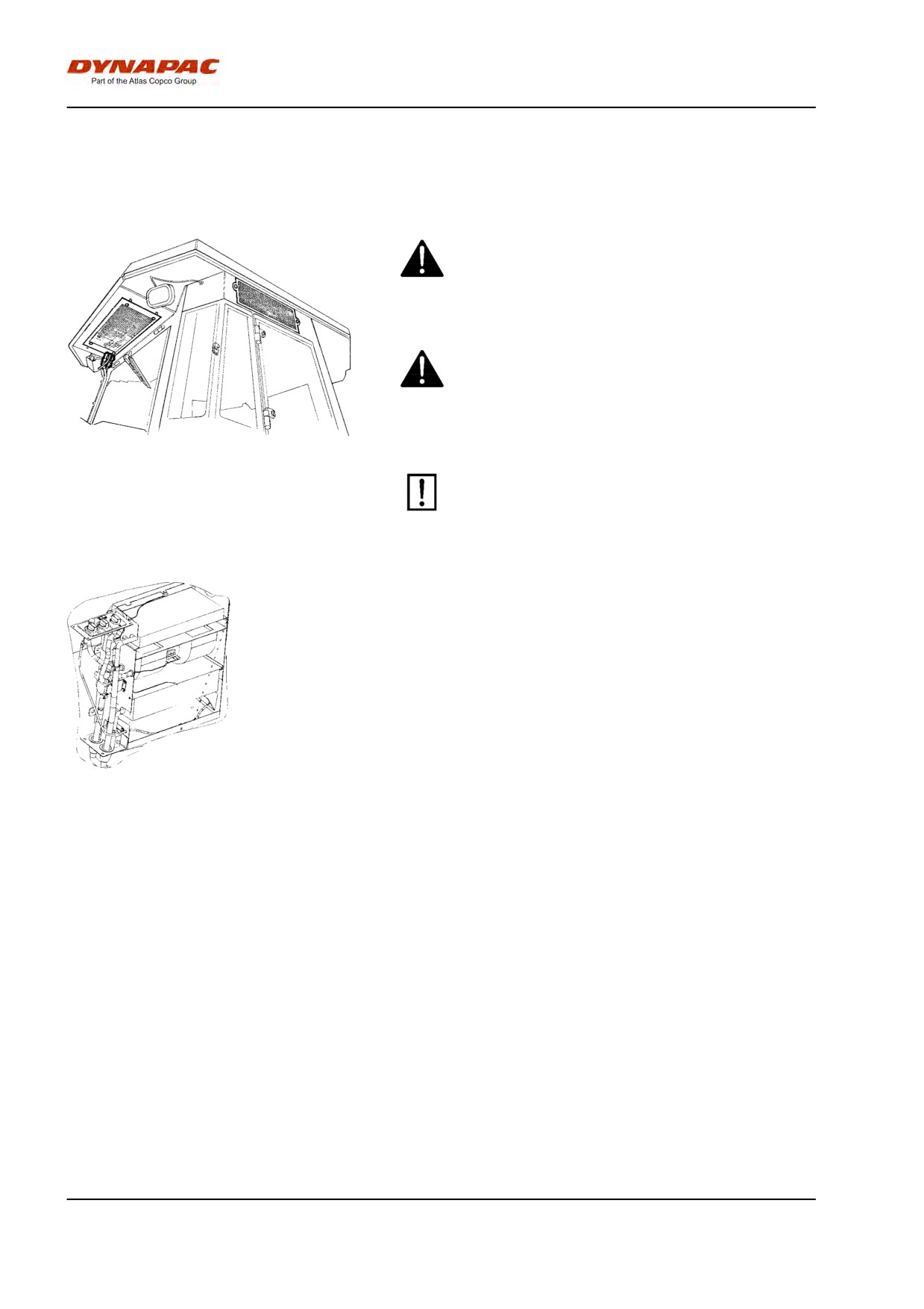
The system described in this manual is type ACC
(Automatic Climate Control)
The system contains pressurized refrigerant. It
is forbidden to release refrigerants into the
atmosphere.
The cooling system is pressurized. Incorrect
handling can result in serious personal injury.
Do not disconnect or undo the hose couplings.
Fig. Cab
The system must be refilled with an approved
refrigerant by authorized personnel when
necessary.
Fig. Air conditioning
8
Special instructions
Special instructions
Standard lubricants and other recommended
oils and fluids
Before leaving the factory, the systems and
components are filled with the oils and fluids specified
in the lubricant specification. These are suitable for
ambient temperatures in the range -15°C to +40°C
(5°F - 104°F).
The maximum temperature for biological
hydraulic fluid is +35°C (95°F).
Higher ambient temperatures, above +40°C
(104°F)
For operation of the machine at higher ambient
temperatures, however maximum +50°C (122°F), the
following recommendations apply:
The diesel engine can be run at this temperature using
normal oil. However, the following fluids must be used
for other components:
Hydraulic system - mineral oil Shell Tellus T100 or
similar.
Other components that use transmission oil: Shell
Spirax AX 85W/140 or equivalent.
Temperatures
The temperature limits apply to standard versions of
rollers.
Rollers equipped with additional equipment, such as
noise suppression, may need to be more carefully
monitored in the higher temperature ranges.
High pressure cleaning
Do not spray directly onto electrical components.
9
Special instructions
High-pressure washing must not be used on the
instrument panel.
Detergent that can destroy electrical parts, or
which is conductive, must not be used.
In certain cases there is an electric operating
lever and an attendant program box in the engine
compartment, which must not be washed with
high-pressure washing or otherwise washed with
water. It is sufficient to wipe them clean.
Place a plastic bag over the fuel filler cap and secure
with a rubber band. This is to avoid high pressure
water entering the vent hole in the filler cap. This could
cause malfunctions, such as the blocking of filters.
Never aim the water jet directly at the fuel tank
cap. This is particularly important when using a
high-pressure cleaner.
Fire fighting
If the machine catches fire, use an ABE-class powder
fire extinguisher.
A BE-class carbon dioxide fire extinguisher can also
be used.
Roll Over Protective Structure (ROPS), ROPS
approved cab
If the machine is fitted with a Roll Over
Protective Structure (ROPS, or ROPS approved
cab) never carry out any welding or drilling in
the structure or cab.
Never attempt to repair a damaged ROPS
structure or cab. These must be replaced with
new ROPS structure or cabs.
Battery handling
When removing batteries, always disconnect the
negative cable first.
10
Special instructions
When fitting batteries, always connect the
positive cable first.
Dispose of old batteries in an environmentally
friendly way. Batteries contain toxic lead.
Do not use a quick-charger for charging the
battery. This may shorten battery life.
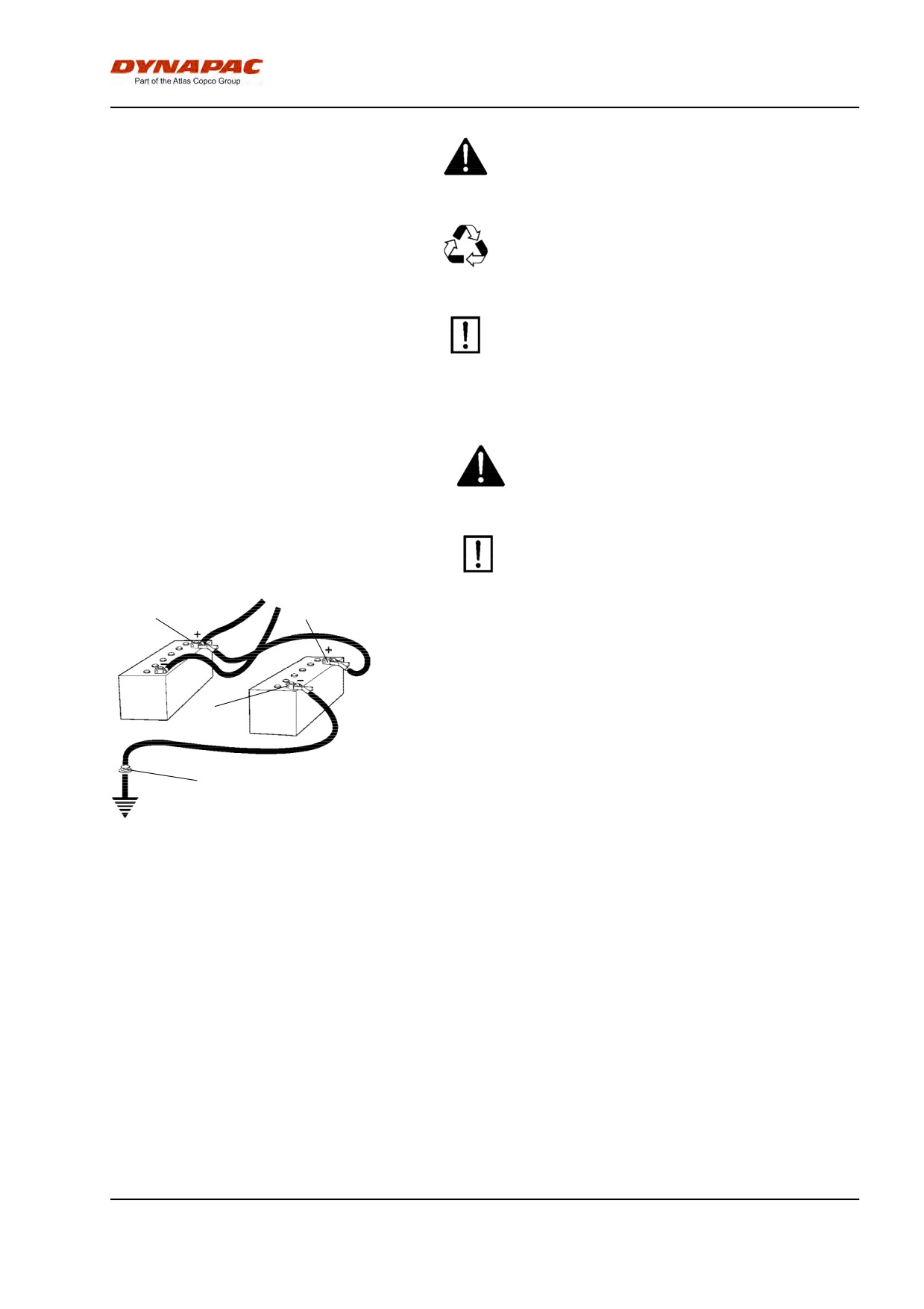
Jump starting
Do not connect the negative cable to the
negative terminal on the dead battery. A spark
can ignite the oxy-hydrogen gas formed
around the battery.
Check that the battery used for jump starting
has the same voltage as the dead battery.
2
1
Turn the ignition and all power consuming equipment
off. Switch off the engine on the machine which is
providing jump start power.
First connect the jump start battery's positive terminal
(1) to the flat battery's positive terminal (2).Then
3
connect the jump start battery's negative terminal (3)
to, for example, a bolt (4) or the lifjting eye on the
machine with the flat battery.
4
Start the engine on the power providing machine. Let it
run for a while. Now try to start the other machine.
Disconnect the cables in the reverse order.
Fig. Jump starting
11
Special instructions
12
Technical specifications - Noise/Vibrations/Electrical
Technical specifications -
Noise/Vibrations/Electrical
Vibrations - Operator station
(ISO 2631)
The vibration levels are measured in accordance with the operational cycle described in
EU directive 2004/14/EC on machines equipped for the EU market, with vibration switched
on, on soft polymer material and with the operator’s seat in the transport position.
Measured whole-body vibrations are below the action value of 0.5 m/s² as specified in Directive
2002/44/EC. (Limit is 1.15 m/s²)
Measured hand/arm vibrations also were below the action level of 2.5 m/s² specified in the same
directive. (Limit is 5 m/s²)
Noise level
The noise level is measured in accordance with the operational cycle described in EU
directive 2004/14/EC on machines equipped for the EU market, on soft polymer material
with vibration switched on and the operator's seat in the transport position.
Guaranteed sound power level, LwA
108 dB (A)
Sound pressure level at the operator's ear (platform), LpA
84 dB (A)
Sound pressure level at the operator's ear (cab), LpA
77 dB (A)
Electrical system
Machines are EMC tested in accordance with EN
13309:2000 'Construction machinery'
13
Technical specifications - Noise/Vibrations/Electrical
14
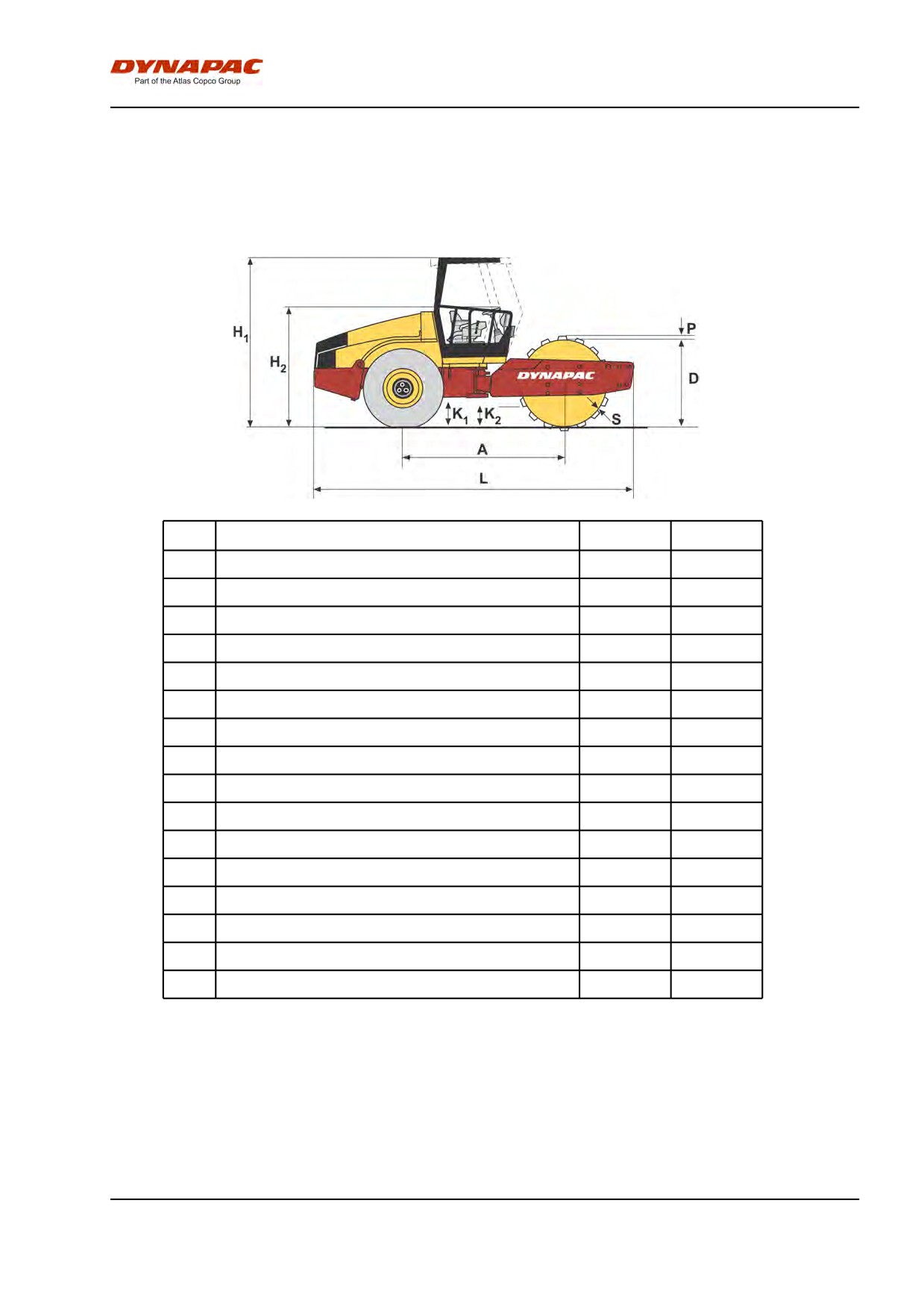
Technical specifications - Dimensions
Technical specifications - Dimensions
Dimensions, side view
Dimensions
mm
in
A
Wheelbase, drum and wheel
2879
113.3
L
Length, standard equipped roller
5758
226,7
H1
Height, with ROPS (D)
2980
117,3
H1
Height, with ROPS (PD)
2996
117,9
H1
Height, with cab (D)
2980
117,3
H1
Height, with cab (PD)
2996
117,9
H2
Height, without ROPS (D)
2190
86
H2
Height, without ROPS (PD)
2212
87,08
D
Diameter, drum (D)
1543
60,75
D
Diameter, drum (PD)
1523
59.96
S
Thickness, drum sweep, nominal (D)
35
1,378
S
Thickness, drum sweep, nominal (PD)
25
0.984
P
Height, pads (PD)
100
3.94
K1
Clearance, tractor frame (D/PD)
453
17.83
K2
Clearance, drum frame (D)
400
15.74
K2
Clearance, drum frame (PD)
495
19.48
15
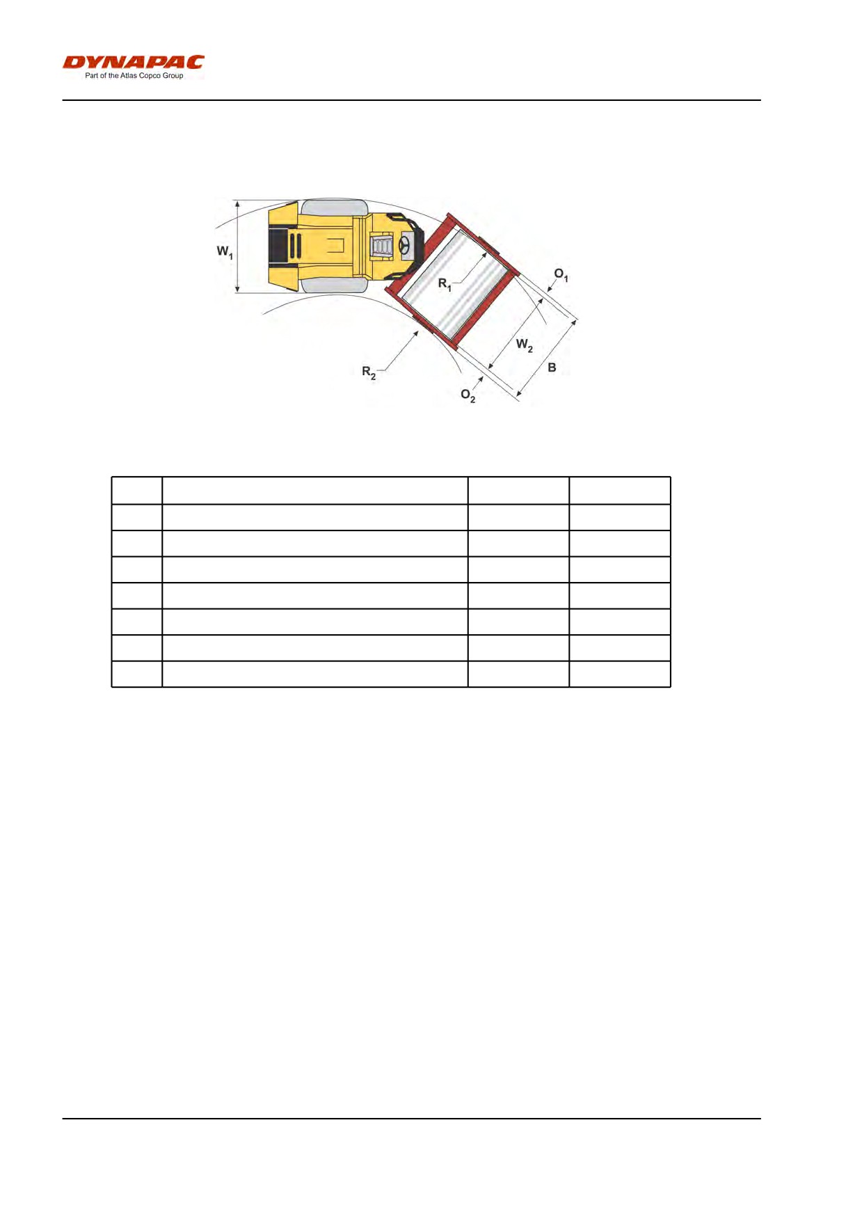
Technical specifications - Dimensions
Dimensions, top view
Dimensions
mm
in
B
Width, standard equipped roller
2384
93,85
O1
Overhang, left frame side
127
5
O2
Overhang, right frame side
127
5
R1
Turn radius, external
5400
212.6
R2
Turn radius, internal
3100
122
W1
Width, tractor section
2130
83.86
W2
Width, drum
2130
83.86
16
Technical specifications - Weights and volumes
Technical specifications - Weights and
volumes
Weights
Service weight with ROPS (EN500)
13050 kg
28775 lbs
(D)
Service weight with ROPS (EN500)
12950 kg
28555 lbs
(PD)
Service weight without ROPS (D)
12550 kg
27672 lbs
Service weight without ROPS (PD)
12450 kg
27452 lbs
Service weight with cab (D)
13050 kg
28775 lbs
Service weight with cab (PD)
12950 kg
28555 lbs
Fluid volumes
Rear axle
- Differential
12 liter
12.7 qts
- Planetary gear (standard
2.0 liters/side
2.1 qts/side
axel)
- Planetary gear (optional
1.85 liter/side
1.9 qts/side
shaft)
Drum gearbox
3.0 liter
3,2 qts
Drum cartridge
2.3 liters/side
2.4 qts/side
Hydraulic reservoir
52 liters
13.7 gal
Oil in hydraulic system
23 liters
6 gal
Lubrication oil, diesel
14 liter
14,8 qts
engine
Coolant, diesel engine
29 liter
7,7 gal
Fuel tank
320 liters
84,5 gal
17
Technical specifications - Weights and volumes
18
Technical specifications - Working capacity
Technical specifications - Working
capacity
Compaction data
Static linear load (D)
37,5 kg/cm
210 pli
Static linear load (PD)
-
-
-
-
Static linear load with ROPS (D)
37,9 kg/cm
212 pli
Static linear load with ROPS (PD)
-
-
-
-
Static linear load with cab (D)
38,3 kg/cm
214 pli
Static linear load with cab (PD)
-
-
-
-
Amplitude, high (D)
1.7 mm
0.066 in
Amplitude, high (PD)
1.6 mm
0,062 in
Amplitude, low (D/PD)
0.8 mm
0.031 in
Vibration frequency, high amplitude (D/PD)
33 Hz
1980 vpm
Vibration frequency, low amplitude (D/PD)
33 Hz
1980 vpm
Centrifugal force, high amplitude (D/PD)
300 kN
67500 lb
Centrifugal force, low amplitude (D/PD)
146 kN
32850 lb
Note: The frequency is measured at high revs. The
amplitude is measured as the real value and not
the nominal.
19
Technical specifications - Working capacity
20
Technical specifications - General
Technical specifications - General
Engine
Manufacturer/Model
Cummins QSB 6.7C
Water cooled turbo diesel
with after cooler
Power (SAE J1995)
112 kW
150 hp
Engine speed, idling
900 rpm
Engine speed, loading/unloading
1,500 rpm
Engine speed, working/transport
2,200 rpm
Electrical system
Battery
12V 170Ah
Alternator
12V 95A
Fuses
See the Electrical system section - fuses
Tire
Tire dimensions
Tire pressure
Std-type
23.1 x 26.0 12 ply
110 kPa (1.1 kp/cm) (16 psi)
Tractor type
23.1 x 26.0 12 ply
110 kPa (1.1 kp/cm) (16 psi)
The tires can be optionally filled with fluid, (extra
weight up to 700 kg/tire) (1,543 lbs/tire). When
servicing, bear this extra weight in mind.
21
Technical specifications - General
Tightening torque
Tightening torque in Nm (lbf.ft) for oiled or dry bolts
tightened with a torque wrench.
Metric coarse screw thread, bright galvanized (fzb):
STRENGTH CLASS:
M -
8.8, Oiled
8.8, Dry
10.9, Oiled
10.9, Dry
12.9, Oiled
12.9, Dry
thread
M6
8,4
9,4
12
13,4
14,6
16,3
M8
21
23
28
32
34
38
M10
40
45
56
62
68
76
M12
70
78
98
110
117
131
M14
110
123
156
174
187
208
M16
169
190
240
270
290
320
M20
330
370
470
520
560
620
M22
446
497
626
699
752
839
M24
570
640
800
900
960
1080
M30
1130
1260
1580
1770
1900
2100
Metric coarse thread, zinc-treated
(Dacromet/GEOMET):
STRENGTH CLASS:
M - thread
10.9, Oiled
10.9, Dry
12.9, Oiled
12.9, Dry
M6
12,0
15,0
14,6
18,3
M8
28
36
34
43
M10
56
70
68
86
M12
98
124
117
147
M14
156
196
187
234
M16
240
304
290
360
M20
470
585
560
698
M22
626
786
752
944
M24
800
1010
960
1215
M30
1580
1990
1900
2360
22
Technical specifications - General
ROPS-bolts which are to be torque tightened
must be dry.
ROPS - bolts
Bolt dimensions :
M24 (PN 904562)
Strength class :
10.9
Tightening torque :
800 Nm (Dacromet
treated)
Hydraulic system
Opening pressure
MPa
Drive system
38,0
Supply system
2.0
Vibration system
40,0
Control systems
18,0
Brake release
1,4
Automatic Climate Control (ACC) (Optional)
The system described in this manual is type ACC
(Automatic Climate Control), i.e. a system which
maintains the set temperature in the cab provided the
windows and doors are kept closed.
Coolant designation: HFC-R134:A
Coolant weight when full: 1600 gram (3.53 lbs)
23
Technical specifications - General
24
Machine plate - Identification
Machine plate - Identification
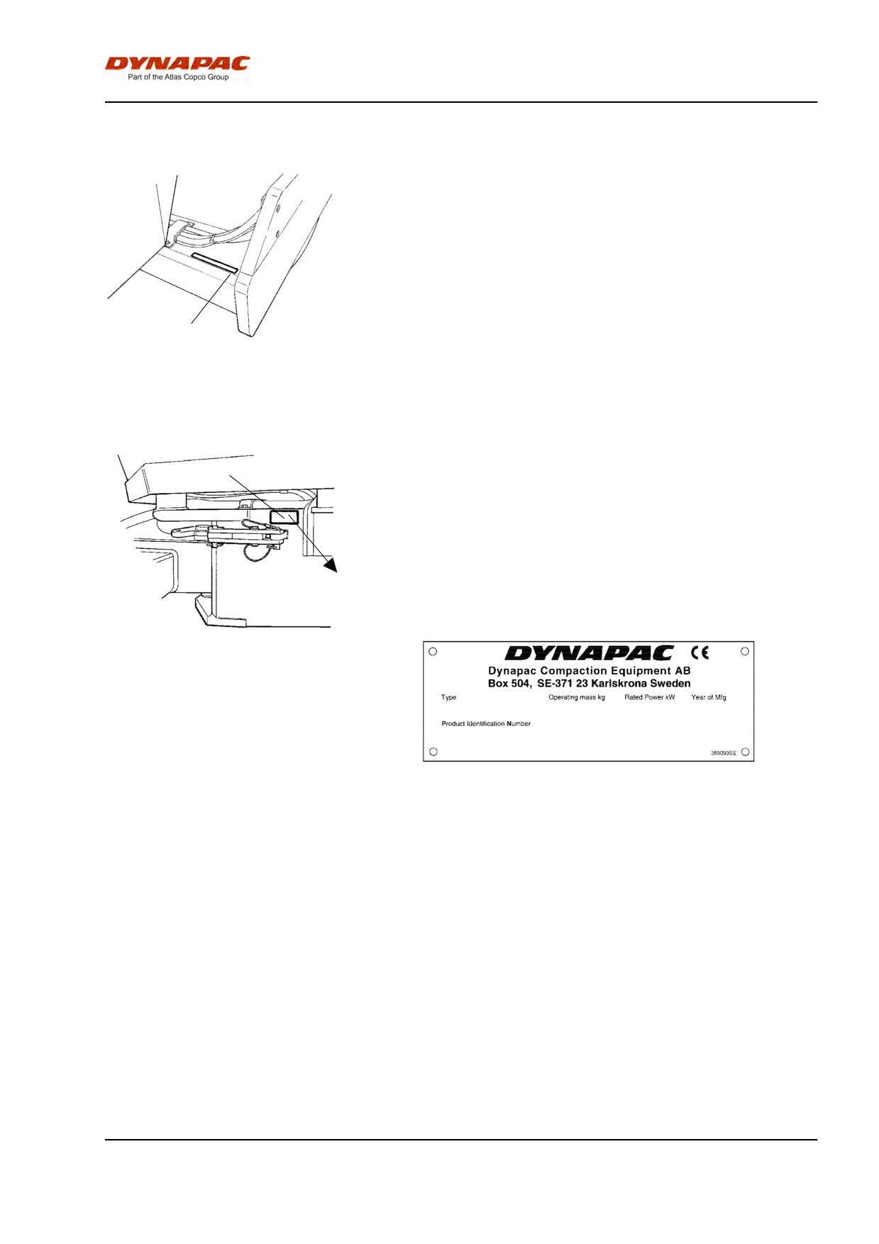
Product identification number on the frame
The machine PIN (product identification number) (1) is
punched on the right edge of the front frame.
1
Fig. Front frame
1. PIN
Machine plate
1
The machine type plate (1) is attached to the front left
side of the frame, beside the steering joint.
The plate specifies the manufacturer's name and
address, the type of machine, the PIN product
identification number (serial number), service weight,
engine power and year of manufacture. (If the
machine is delivered outside the EU there are no CE
markings, and on some machines the year of
manufacture may not be specified.)
Fig. Operator platform
1. Machine plate
Please state the machine's PIN when ordering
spares.
25
Machine plate - Identification
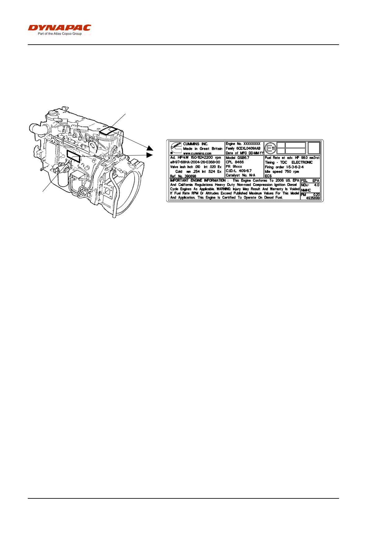
Engine plates
The engine type plates (1) are affixed to the top and
on the right side of the engine.
The plates specify the type of engine, serial number
and the engine specification.
1
Please specify the engine serial number when
ordering spares. Refer also to the engine manual.
1
Fig. Engine
1. Type plate/EPA plate
26
Machine plate - Identification
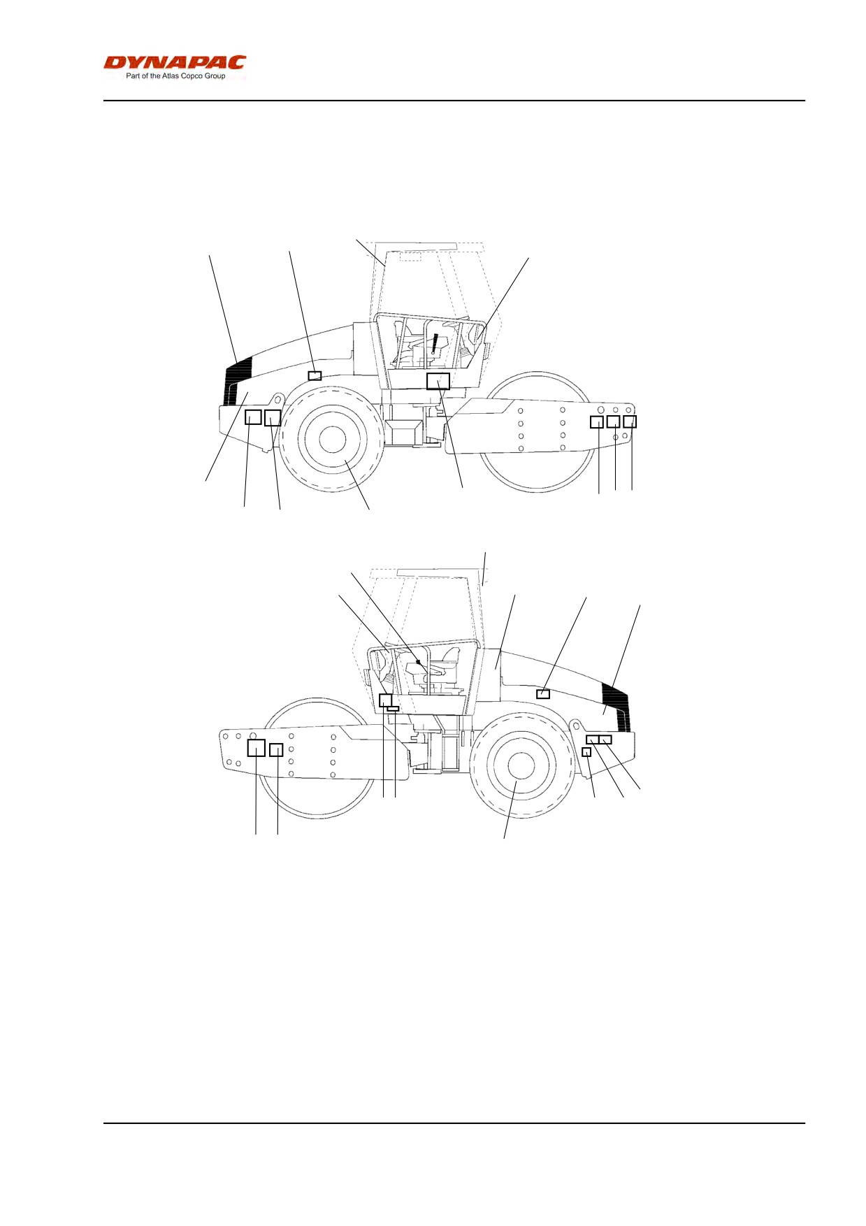
Decals
Location - decals
2, 3
10
5
6
11
1
79
15
15
4
12
8
16
18
14
10
17
15
13
1
7
9
12
15
4
1.
Warning, Crush zone
7.
Warning, Locking
13.
Sound power level
2.
Warning, Rotating engine
8.
Warning, Toxic gas
14.
Hydraulic
components
fluid/Biohydraulic fluid
3.
Warning, Hot surfaces
9.
Hoisting plate
15.
Tie down point
4.
Warning, Ballasted tire.
10.
Tire pressure
16.
Handbook compartment
5.
Emergency exit
11.
Diesel fuel
17.
Battery master switch
6.
Warning, Read instructions manual 12.
Lift point
18.
Warning sign
27
Machine plate - Identification
Safety decals
4700903422
Warning - Crush zone, articulation/drum.
Maintain a safe distance from the crush zone.
(Two crush zones on machines fitted with pivotal steering)
4700903423
Warning - Rotating engine components.
Keep your hands at a safe distance from the
danger zone.
4700903424
Warning - Hot surfaces in the engine compartment.
Keep your hands at a safe distance from the
danger zone.
4700903985
Warning - Ballasted tire.
Read the instruction manual.
4700903590
-Emergency exit
4700903459
Warning - Instruction manual
The operator must read the safety, operation and
maintenance instructions before operating the
machine.
28
Machine plate - Identification
4700908229
Warning - Locking
The articulation must be locked when lifting.
Read the instruction manual.
4700904165
Warning - Toxic gas (accessory, ACC)
Read the instruction manual.
29
Machine plate - Identification
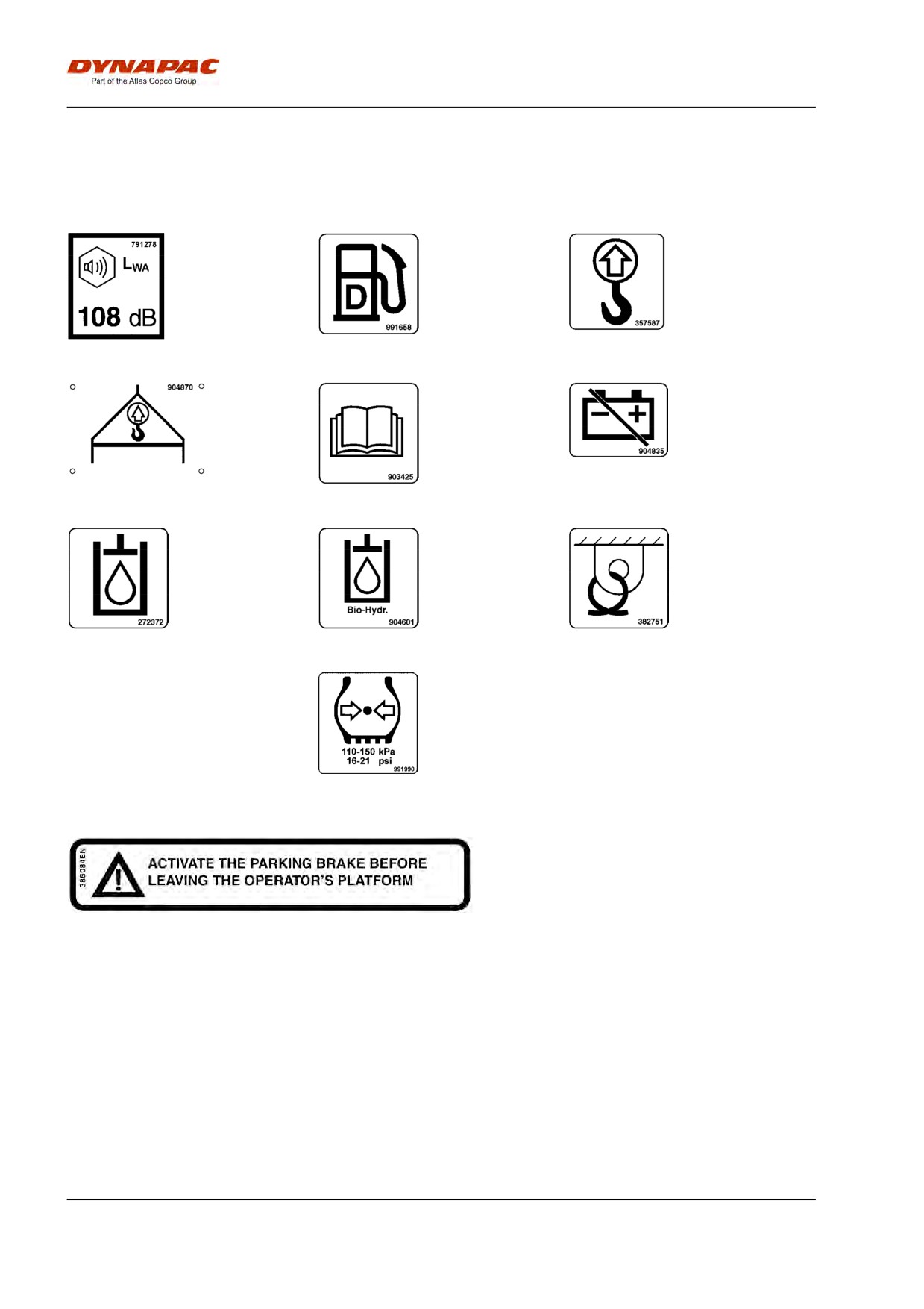
Info decals
Noise power level
Diesel fuel
Lifting point
Hoisting plate
Handbook compartment
Master switch
Hydraulic fluid
Biological hydraulic fluid
Tie down point
Tire pressure
30
Machine description - Instruments/Controls
Machine description -
Instruments/Controls
Instruments/Controls
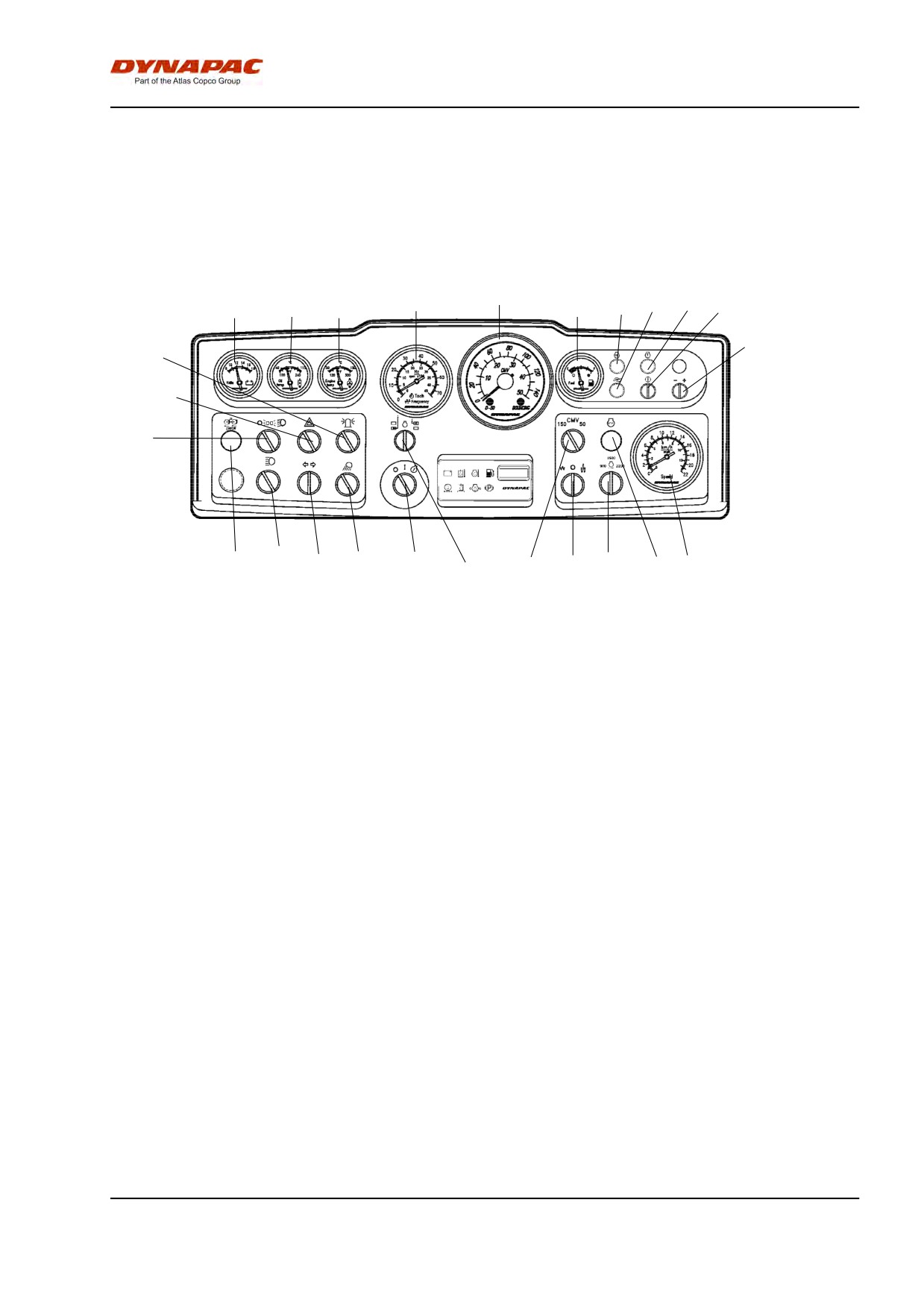
Locations - Instruments and controls
14
10
11
13
15
16
17
18
19
12
20
4
6
8
9
7
5
3
1
2
25
24
23
22
21
Fig. Instruments and control panel
1.
Starter switch
2.
Rpm/Frequency selector
3.
Working lights
4.
Hazard beacon
5.
Direction indicator switch
6.
Hazard warning lights
7.
Main beam switch
8.
Parking/dipped beam switch
9.
Anti-spin, fault indication
10.
Voltmeter
11.
Hydraulic temperature
12.
Engine temperature
13.
Engine revs/Vibration frequency
14.
Compaction meter/Speedometer (see pos. 21)
15.
Fuel gauge
16.
Preheating lamp
17.
Reserve
18.
Fault indicating lamp
19.
Diagnostics "ON"
20.
Browse in error codes
21.
Speedometer (if compaction meter is located in pos. 14)
22.
Fault indicating lamp
23.
Engine speed control
24.
Amplitude selector, High/0/Low
25.
CMV väljare
* = Optional equipment
31
Machine description - Instruments/Controls
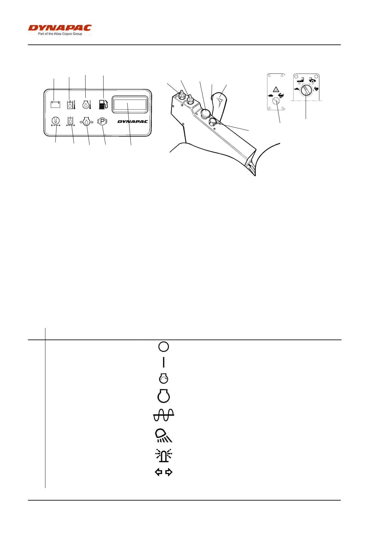
Locations - Control panel and controls
31
32
33
34
36
35
37
38
39
35
41
40
30
29
28
27
26
Fig. Control panel
26.
Hourmeter
34.
Warning lamp, fuel level
27.
Brake warning lamp
35.
Speed selector, drum/wheels (Optional)
28.
Warning lamp, engine oil pressure
36.
Speed selector, wheels
29.
Warning lamp, hydraulic fluid filter
37.
Reserve/Parking brake knob
30.
Warning lamp, air filter
38.
Vibration ON/OFF
31.
Warning lamp, charging
39.
Forward/Reverse lever
32.
Warning lamp, hydraulic fluid temperature
40.
Horn
33.
Warning lamp, engine temperature
41.
Antispin function (Optional)
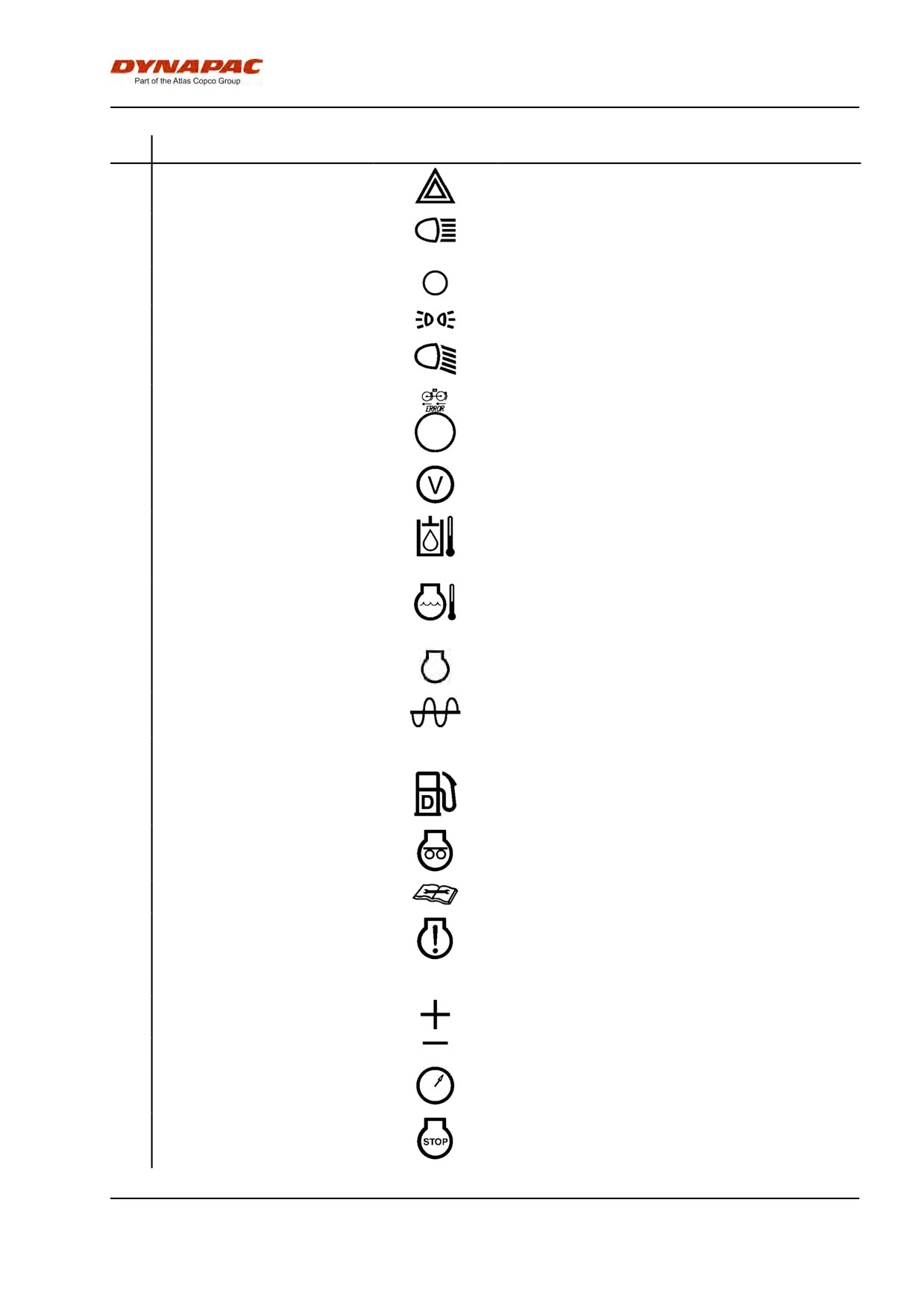
Function descriptions
No
Designation
Symbol
Function
1
Starter switch
The electric circuit is broken.
All instruments and electric controls are supplied with
power.
Starter motor activation.
2
Engine revs/Frequency selector
The current rpm is shown in this position
(Optional)
The vibration frequency is shown in this position (Left
position has no function.
3
Rear working lights switch
Turn right to switch on the working lights.
(Optional).
4
Hazard beacon, switch
Turn right to switch on the hazard beacon.
(Optional).
5
Direction indicator, switch
Turn to the left to switch on the left direction indicators
(Optional).
etc.
The direction indicators are off in the middle position.
32
Machine description - Instruments/Controls
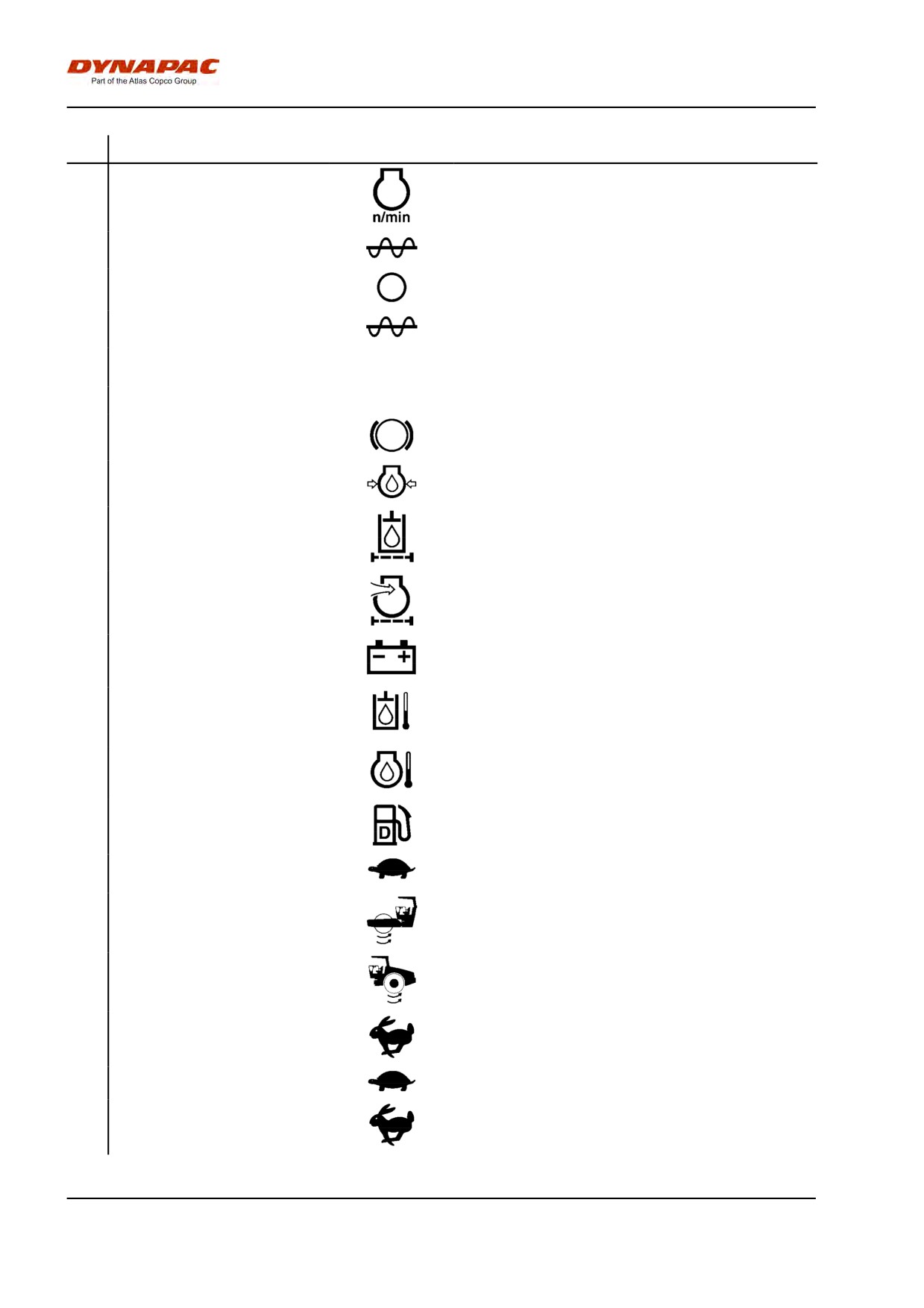
No
Designation
Symbol
Function
6
Hazard flashers, switch
Turn to the right to switch on the hazard flashers.
(Optional).
7
Main/dipped beam, switch with
In the right position, the switch lights and the main
control lamp (Optional).
beam is on.
In the left position, the dipped beam is on.
8
Driving lighting, switch
Lights off.
(Optional).
Parking lights on.
Front working lights on.
9
Warning lamp, malfunctioning
The hydraulic propulsion system is not working
anti-spin function (Optional)
satisfactorily if the lamp flashes. Locate and remedy
the fault.
10
Voltmeter (Optional).
Shows electrical system voltage.
Normal range is 12-15 volts.
11
Temperature gauge, hydraulic
Shows hydraulic fluid temperature.
fluid (Optional).
Normal temperature range is 65°-80°C (149°-176°F).
Stop the engine if the gauge shows a temperature of
more than 85°C (185°F). Locate the fault.
12
Temperature gauge, water
Shows the water temperature.
(Optional).
Normal temperature is around 90°C (194°F).
Stop the engine if the gauge shows a temperature of
more than 103°C (217°F). Locate the fault.
13
Engine revs/Frequency meter
The inner scale indicates the current engine speed.
(Optional).
The outer scale shows the vibration frequency.
14
Compaction meter (Optional)
See separate instructions
15
Fuel gauge
Shows level in the fuel tank.
16
Preheating lamp
Lights up when the diesel engine is being preheated
and the switch is in position I.
17
Reserve
18
Fault indicating lamp, "Minor
Indicates fault and shows error code together with knob
fault"
19. See error codes under tab X in machine folder.
19
Diagnostics "ON"
Check error code together with lamp 18 and 20.
20
Browse in error codes
Turning to right (+): Stepping forward.
Turning to left (-): Stepping backwards.
21
Speedometer (Optional).
The outer scale shows speed in km/h.
The inner scale shows speed in mph.
22
Fault indicating lamp, "Serious
Stop the engine.
fault"
33
Machine description - Instruments/Controls
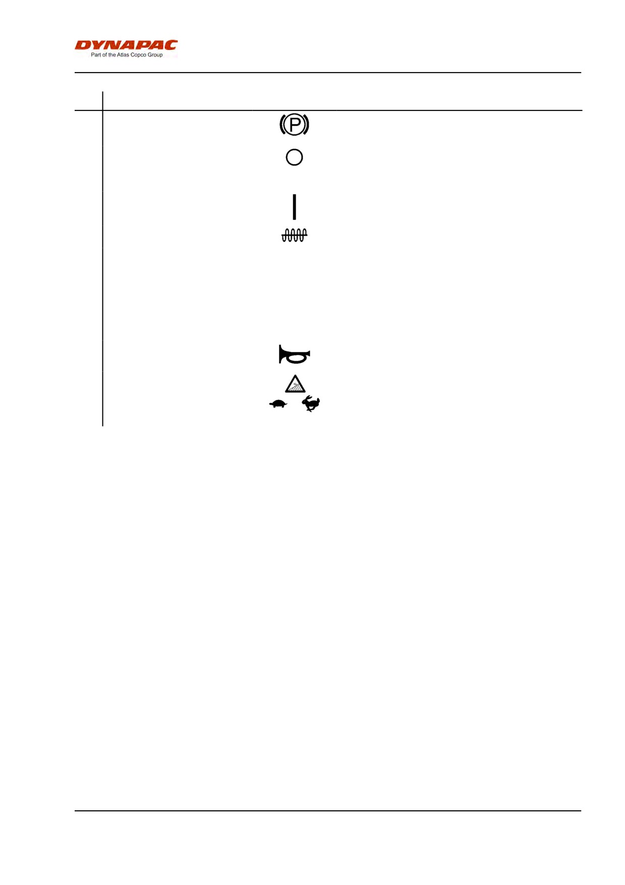
No
Designation
Symbol
Function
23
Engine speed control for Diesel
900 = Idling speed
engine
1,500 = Speed for loading/unloading
2,200 = Working and transport speed
24
Amplitude selector.
Left mode gives low amplitude.
In the 0 position, the vibration system is switched off.
Right mode gives high amplitude.
25
CMV selector (Optional).
Mode 150 gives reading on outer scale.
Mode 50 gives reading on inner scale.
26
Hourmeter
Engine running time is shown in hours.
27
Brake warning lamp
The lamp come on when the parking or emergency
brake knob is depressed and the brakes are applied.
28
Warning lamp, oil pressure
The lamp comes on if the engine oil pressure is too low.
Stop the engine immediately and locate the fault.
29
Warning lamp, hydraulic filter
If the lamp comes on while the engine is running at full
speed, the hydraulic filter must be changed.
30
Warning lamp, air filter
If the lamp comes on while the engine is running at full
speed, the air filter must be cleaned or replaced.
31
Warning lamp, battery charging
If the lamp comes on while the engine is running, the
alternator is not charging.
Stop the engine and locate the fault.
32
Warning lamp, hydraulic fluid
If the lamp comes on, the hydraulic fluid is too hot.
temperature
Do not drive the roller. Cool the fluid by allowing the
engine to idle and locate the fault.
33
Warning light, coolant
If the lamp comes on, the engine is too hot. Stop the
temperature
engine immediately and locate the fault.
Refer also to the engine manual.
34
Warning lamp, low fuel level
When the lamp comes on, there is only a small amount
of fuel left.
Refuel as soon as possible.
35
Speed selector, drum/wheels
Position 1: Working mode
(Optional)
Position 2: Used if the drum spins.
Position 3: Used if the rear tires spin.
Position 4: Transport mode
36
Speed selector, wheels
Transport speed (Low)
Transport speed (High)
34
Machine description - Instruments/Controls
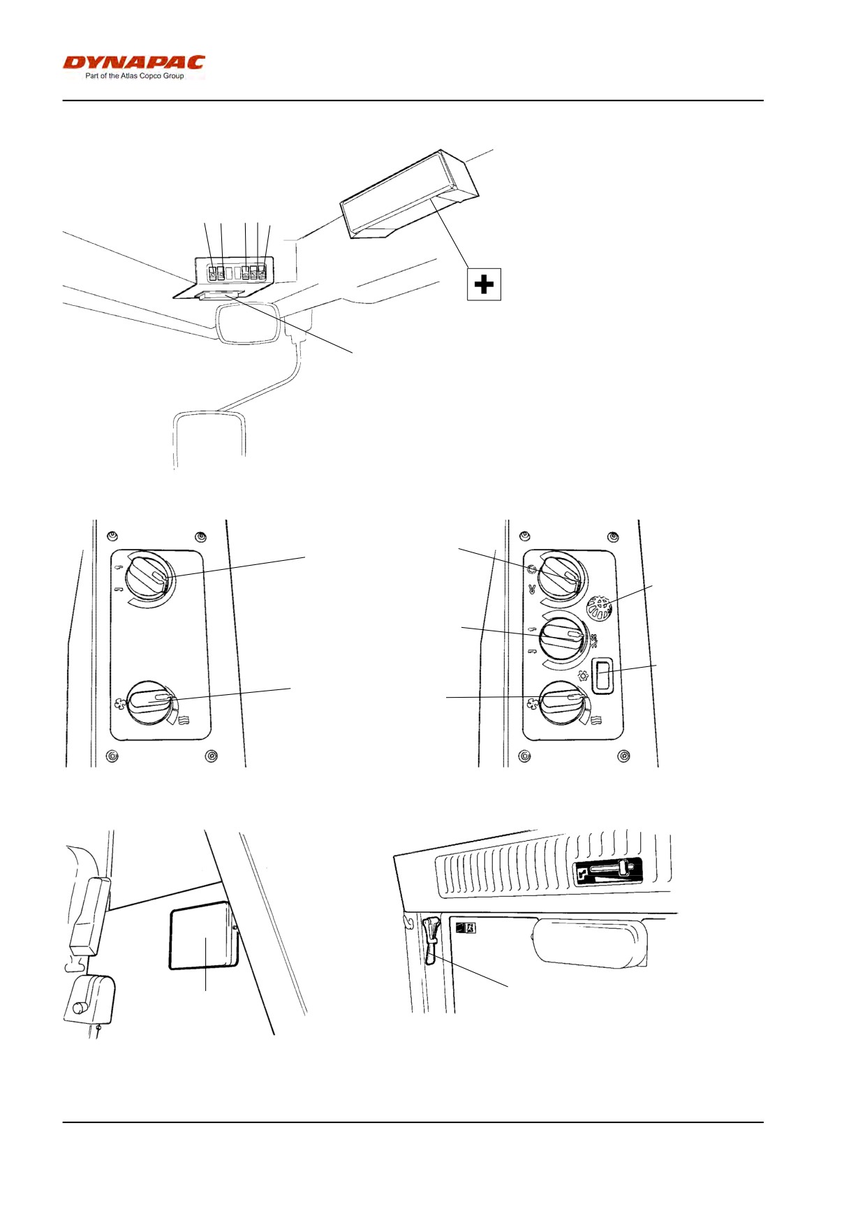
No
Designation
Symbol
Function
37
Emergency brake / Parking
Press to activate the emergency brakes. When the
brake
machine is stationary, the parking brake is activated.
Both brakes are released when pulled out.
38
Vibration On/Off, switch
Press once and release to switch the vibration on,
press again to switch the vibration off.
The above only applies when the amplitude selector 17
is in the High or Low position.
39
Forward/Reverse lever
The lever must be in neutral to start the engine. The
engine cannot be started if the forward/reverse lever is
in any other position.
The forward/reverse lever controls both the roller's
driving direction and speed. When the lever is moved
forward, the roller moves forward.
The roller's speed is proportional to the distance the
lever is from the neutral position. The further the lever
is from the neutral position, the higher the speed.
40
Horn, switch
Press to sound the horn.
41
Antispin function (Optional)
Optimized antispin function forwards is obtained with
the knob in the left position.
Optimized antispin function backwards is obtained with
the knob in the middle position.
Set the knob in the right position during transport.
35
Machine description - Instruments/Controls
Controls in the cab
1 2
345
First-aid kit (optional)
6
Fig. Cab roof, front
9
7
10
7
11
8
8
Fig. Cab right side (AC optional)
Fig. Cab, right side
13
12
Fig. Cab roof, rear
Fig. Cab, rear
36
Machine description - Instruments/Controls
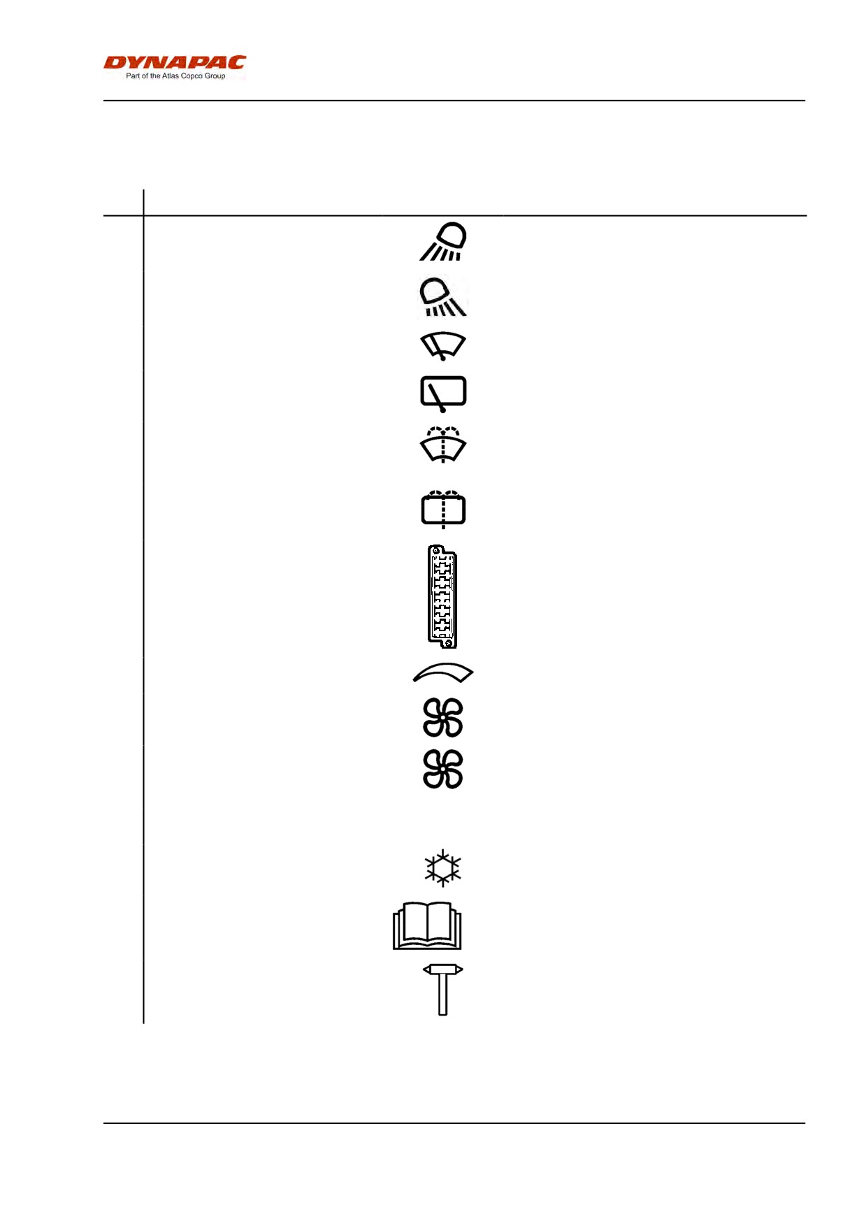
Function description of instruments and
controls in the cab
No
Designation
Symbol
Function
1
Front working lights, switch
Press to switch on the front working lights.
2
Rear working lights, switch
Press to switch on the rear working lights.
3
Front wiper, switch
Press to operate the front screen wiper.
4
Rear wiper, switch
Press to operate the rear screen wiper.
5
Front and rear window screen
Press the upper edge to activate the front screen
washers, switch
washers.
Press the lower edge to activate the rear screen
washers.
6
Fuse box (cab)
Contains fuses for the electrical system. See the
"Electrical system" section in the operation
manual for functional descriptions of the fuses.
7
Heater control
Right mode, maximum heating. In the left
position, the heating is off.
8
Ventilation fan, switch
In the left position, the fan is OFF. To the right,
the fan has three levels.
9
Cab air recirculation, switch
In the left position, the maximum volume of air is
recirculated.
In the right position, the volume recirculated is
minimal.
10
Temperature sensor
Registers the temperature in the cab. Do not
cover.
11
Air conditioning, switch
Starts and stops the air conditioning.
12
Handbook compartment
Stowage space for safety manual and instruction
manuals.
13
Hammer for emergency exit
To escape from the cab in an emergency,
release the hammer and break the REAR
window.
37
Machine description - Instruments/Controls
38
Machine description - Electrical system
Machine description - Electrical system
Electrical system
Fuses
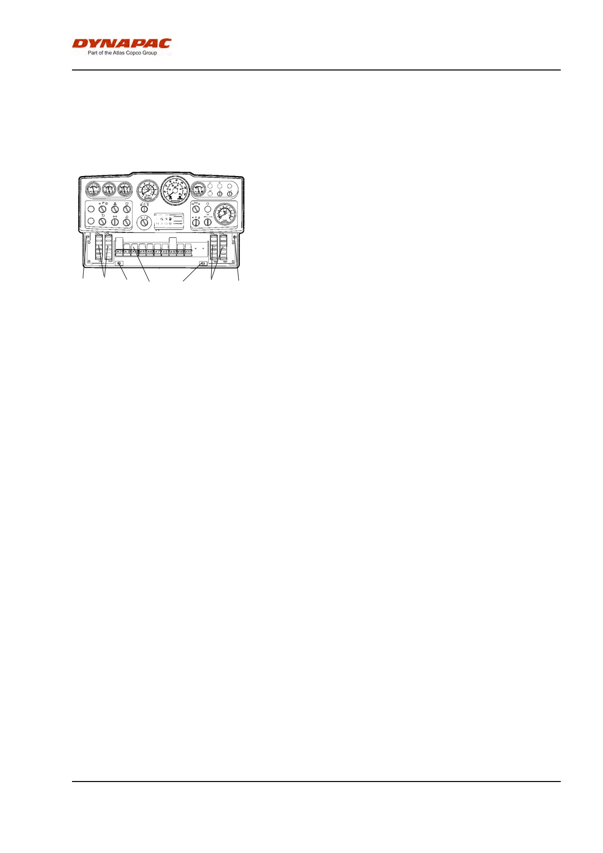
The electrical regulating and control system is
protected against overload by 27 fuses and 12 relays.
The quantity depends on how much extra equipment
the machine has.
The four fuse boxes (1) and relays (3) are located
behind the lower instrument plate, which is opened by
turning the four quick-fit screws (2) a 1/4 turn
counter-clockwise.
2
1
2
3
2
1
2
The machine is equipped with a 12V electrical system
and an AC alternator.
Fig. Instrument panel
1. Fuse boxes (4)
2. Quick-screws
3. Relays
39
Machine description - Electrical system
Fuses
1
7
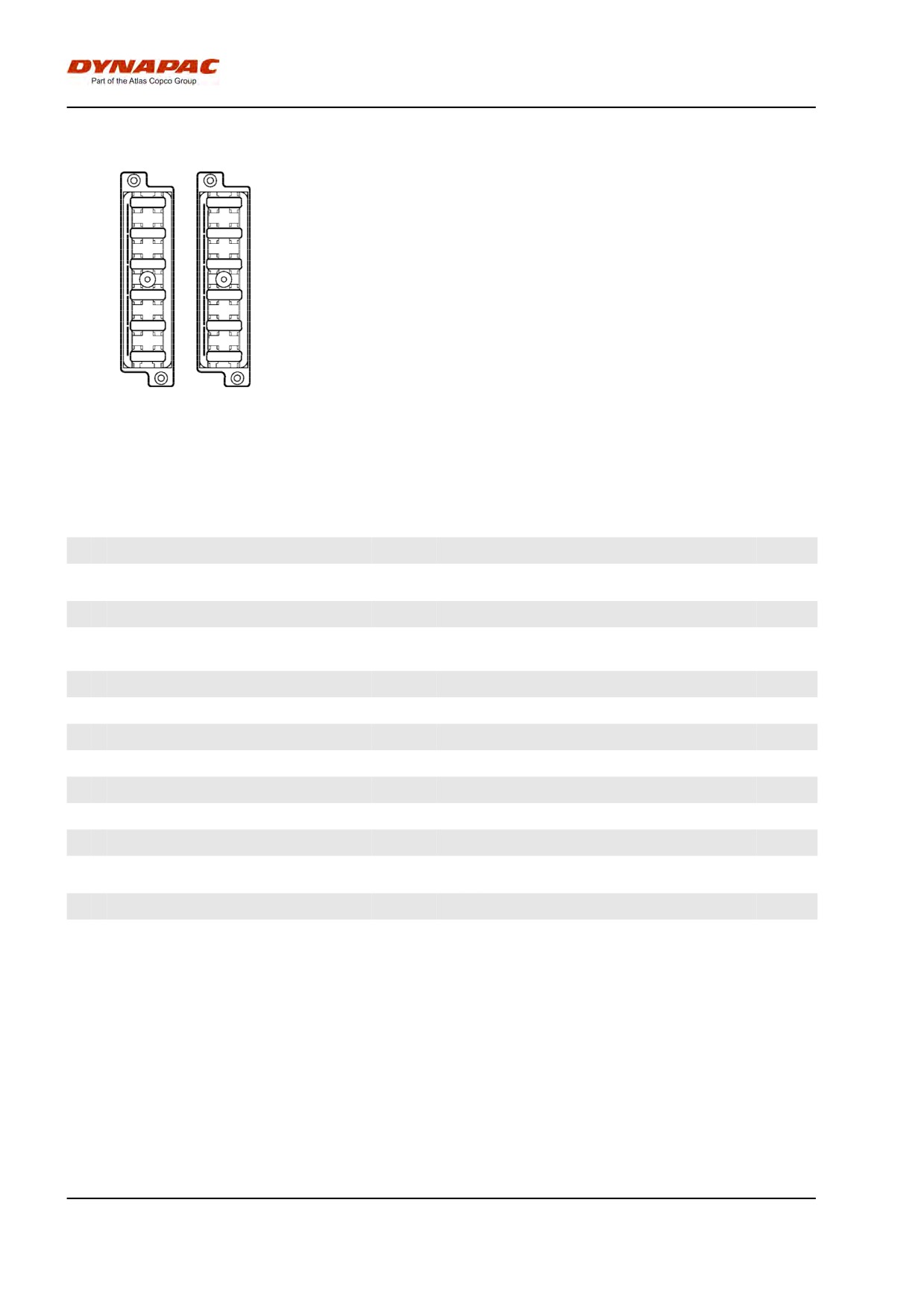
The figure shows the position of the fuses.
2
8
3
9
The table below gives fuse amperage and function. All
fuses are flat pin fuses.
4
10
5
11
The tachograph and memory for the radio are
6
12
protected at the battery master disconnect switch by a
0.5 A and 3 A fuse, respectively.
Fig. Fuse box,
left and right side.
Fuse boxes, left side
Fuse boxes, right side
1.
Brake valve, starter relay, hourmeter
7.5A
1.
* Left working lights
20A
2.
VBS relay
7.5A
2.
* Working lights, right, instrument
20A
illumination
3.
Indicator panel
7.5A
3.
* Headlight, left
7.5A
4.
Horn
7.5A
4.
* Headlight, right, instrument illumination
7.5A
**
5.
* Low/High speed/Strike-off blade
7.5A
5.
Reserve
6.
* Reverse warning
3A
6.
Reserve
7.
Instrumentation
7.5A
7.
* Hazard beacon
10A
8.
* Compaction meter
3A
8.
* Direction indicators, main fuse
10A
9.
* Hazard beacon
7.5A
9.
* Position light, left, front and rear
7.5A
10. * Anti-spin
7.5A
10. * Position light, right, front and rear
5A
11. * Air conditioning
20A
11. * Direction indicator, left, front, rear and side
5A
12. * Air conditioning
20A
12. * Direction indicator, right, front, rear and
5A
side
* Optional
* Optional
** When driving lights are fitted
40
Machine description - Electrical system
Fuses in cab
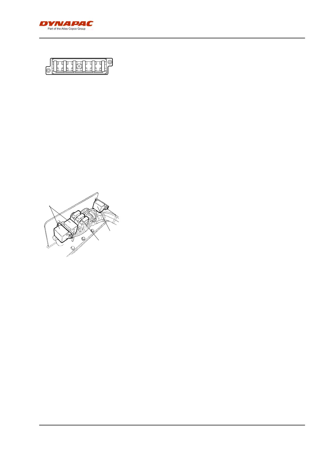
The electrical system in the cab has a separate fuse
box located on the front right side of the cab roof.
1
2
3
4
5
6
The figure shows fuse amperage and function.
Fig. Cab roof fuse box
All fuses are flat pin fuses.
1. Rear cab headlight
20A
2. Front cab headlight, Radio
10A
3. Cab interior lighting
5A
4. Air-Conditioning fan
25A
5. Rear screen wiper/washer
10A
6. Front screen wiper/washers
10A
Main fuses
There are four main fuses (2). They are located behind
3
the battery master disconnect switch. The three
screws need to be unscrewed to remove the plastic
cover.
The fuses are of flat pin type.
1
The starter relay (1) and preheating relays (3) for the
2
diesel engine are also fitted here.
Supply standard
30A
(Green)
Supply cab *
50A
(Red)
Fig. Engine compartment
1. Starter relay
Supply lighting *
40A
(Orange)
2. Main fuses
Supply, Air conditioning*
30A
(Green)
3. Preheating relays
* Optional equipment
41
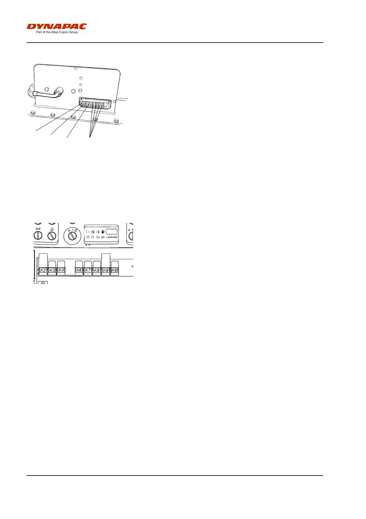
Machine description - Electrical system
Fuses at battery master disconnect switch
Positioning of fuses at battery master disconnect
switch in the engine compartment.
QSB engine (ignition)
5A
Diagnostics lamps, engine
5A
ECM electronics
30A
1
2
3
4
Fig. Engine compartment
1. QSB engine (ignition)
2. Diagnostics lamps engine
3. ECM electronics
4. Reserve
Relays
K2
VBS relay
K3
Main relay
K4
Horn relay
K6
Fuel gauge relay
K7
Reversing alarm relay
K8
Light relay
K9
Indicator relay
Fig. Instrument panel
K10
Brake relay
* Optional
42

Machine description - Electrical system
Relays in cab
2
3
To replace the relays for the air conditioning fan, the
condensor fan on the cab roof and the radio, remove
instrumentpanel (1).
4
1
Fig. Cab roof, front
1. Instrument plate
2. K30 Relay for air conditioning fan
3. K31 Relay for air con fans + radio
4. Fuse box
43
Machine description - Electrical system
44
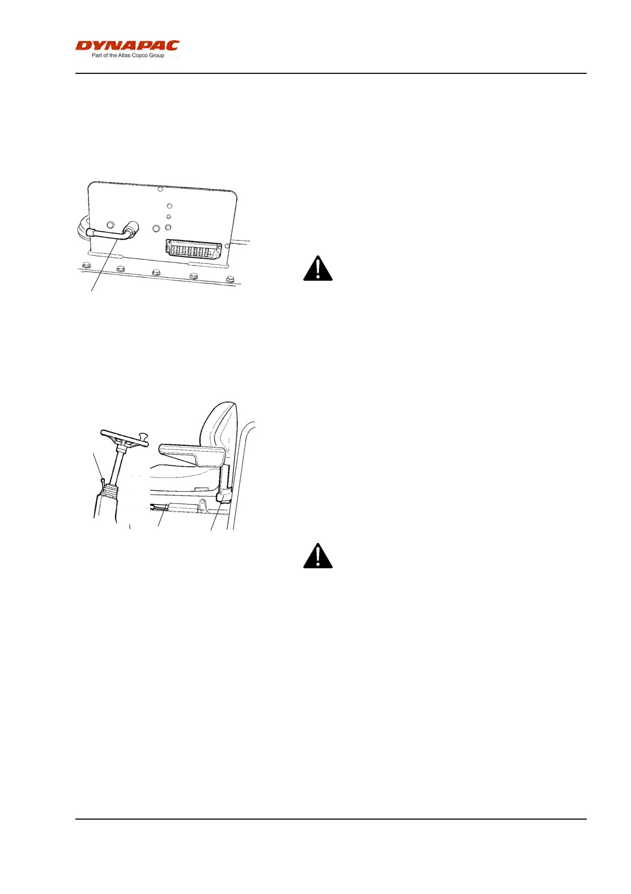
Operation - Starting
Operation - Starting
Before starting
Master switch - Switching on
Remember to carry out daily maintenance. Refer to
the maintenance instructions.
The master switch is located in the engine
compartment. Turn the key (1) to the on position. The
entire roller is now supplied with power.
The engine hood must be unlocked when
operating, so that the battery can be quickly
disconnected if necessary.
1
Fig. Engine compartment
1. Master switch
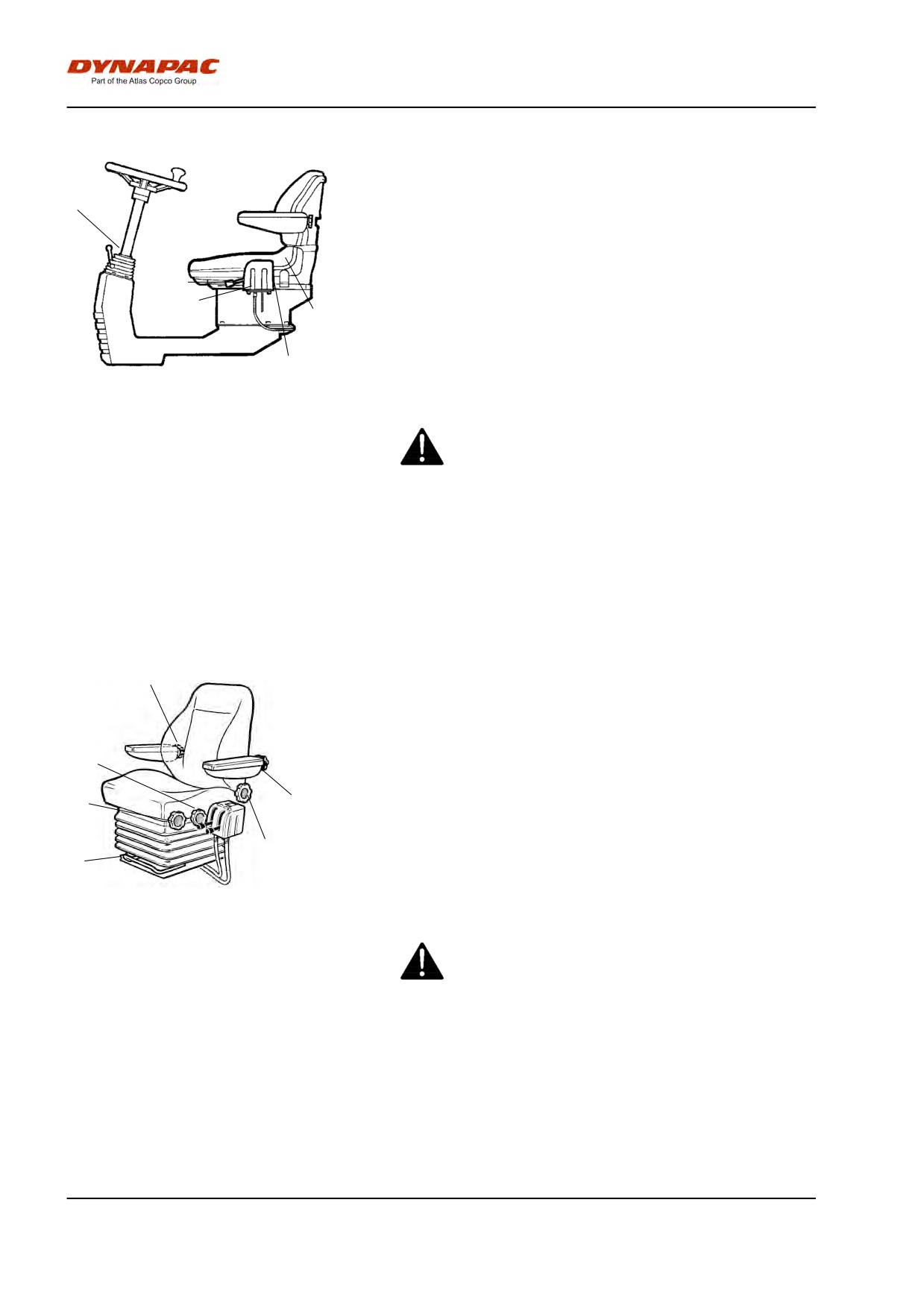
Operator’s seat - Adjusting
Adjust the operator’s seat so that the position is
comfortable and so that the controls are within easy
3
reach.
The seat can be adjusted as follows.
- Length adjustment (1)
- Weight adjustment (2)
Release locking lever (3) to adjust the steering
column. Lock in the new position.
1
2
Always make sure that the seat is secure before
Fig. Operator's seat
beginning operation.
1. Locking lever - Length adjustment
2. Lever - Weight adjustment
3. Locking lever - Steering column
angle
45
Operation - Starting
Control unit - Setting
The control unit has two adjustment options, rotation
and steering column angle.
2
Pull the lever (1) upwards to allow rotation.
Release the locking lever (2) to adjust the steering
column to the desired slope and then lock the steering
4
column in its new position.
3
5
The seat can be adjusted as follows:
- Length adjustment (3)
1
- Back slope (4)
Fig. Operator's station
- Weight adjustment (5)
1. Locking lever - rotation (Optional)
2. Locking lever - steering column
Always make sure that the seat is secure before
angle
beginning operation.
3. Locking lever - length adjustment
4. Lever - backrest slope
5. Lever - weight adjustment
Operator’s seat in cab - Adjusting
6
The control unit has three adjustment options,
transverse travel, rotation and steering column angle.
Adjust the operator's seat so that the position is
3
comfortable and so that the controls are within easy
reach.
2
5
The seat can be adjusted as follows:
- Length adjustment (1)
- Height adjustment (2)
4
- Seat-cushion inclination (3)
1
- Backrest inclination (4)
- Armrest inclination (5)
Fig. Operator’s seat
- Lumbar support adjustment (6)
1. Lever - length adjustment
2. Wheel - height adjustment
3. Wheel - seat cushion inclination
4. Wheel - backrest inclination
Always ensure that the seat is locked in position
5. Wheel - armrest inclination
before operating the roller.
6. Wheel - lumbar support
adjustment
46
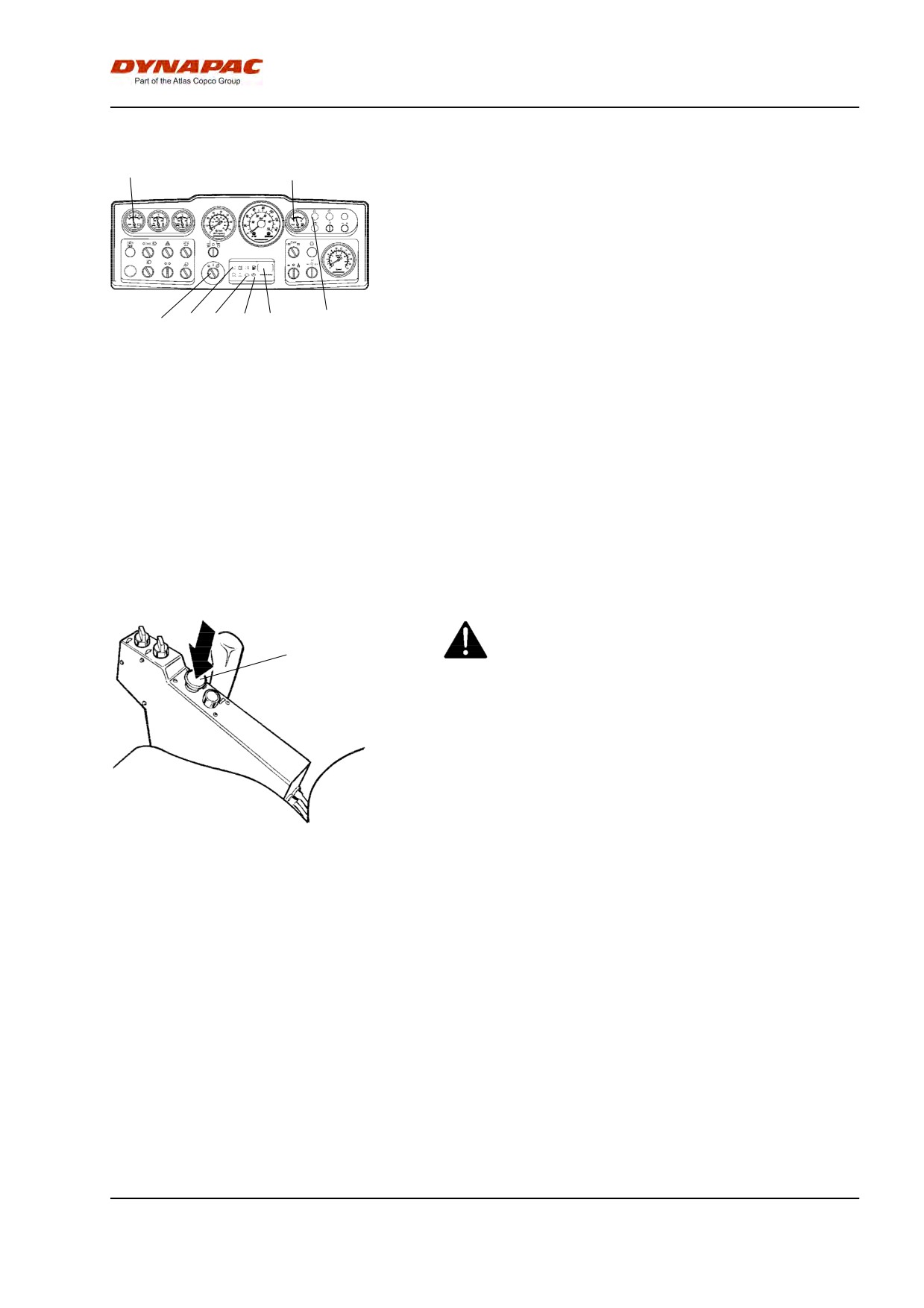
Operation - Starting
Instruments and lamps - Checking
10
15
Turn the switch (1) to the mid-position. All warning
lamps should light for about 5 seconds and the beeper
should sound.
During this time check that the warning lamps light up.
Check that the voltmeter (10) reads at least 12 volts,
and that the fuel gauge (15) shows a reading.
Check that the warning lamps for charging (31), oil
1
31
28
27
26
16
pressure (28), and the parking brake (27) come on.
The hourmeter (26) registers and shows the number of
hours the diesel engine has been running.
Fig. Instrument panel
1. Starter switch
The preheating lamp (16) must go on.
10. Voltmeter (Optional)
15. Fuel gauge
16. Preheating lamp
26. Hourmeter
27. Brake lampa
28. Oil pressure lamp
31. Charging lamp
Parking brake - Check
Make sure that the reserve/parking brake knob (37)
is actually in the pressed-in position. The roller
37
can start to roll when the engine is started on
sloping ground, if the reserve/parking brake is not
applied.
Fig. Control panel
37. Reserve/parking brake knob
47
Operation - Starting
Interlock (Optional)
The roller can be equipped with Interlock.
The engine switches off 7 seconds after the operator
rises from the seat.
The engine stops whether the forward/reverse lever is
in the neutral or the drive position.
The engine does not stop if the parking brake is
activated.
Operator position
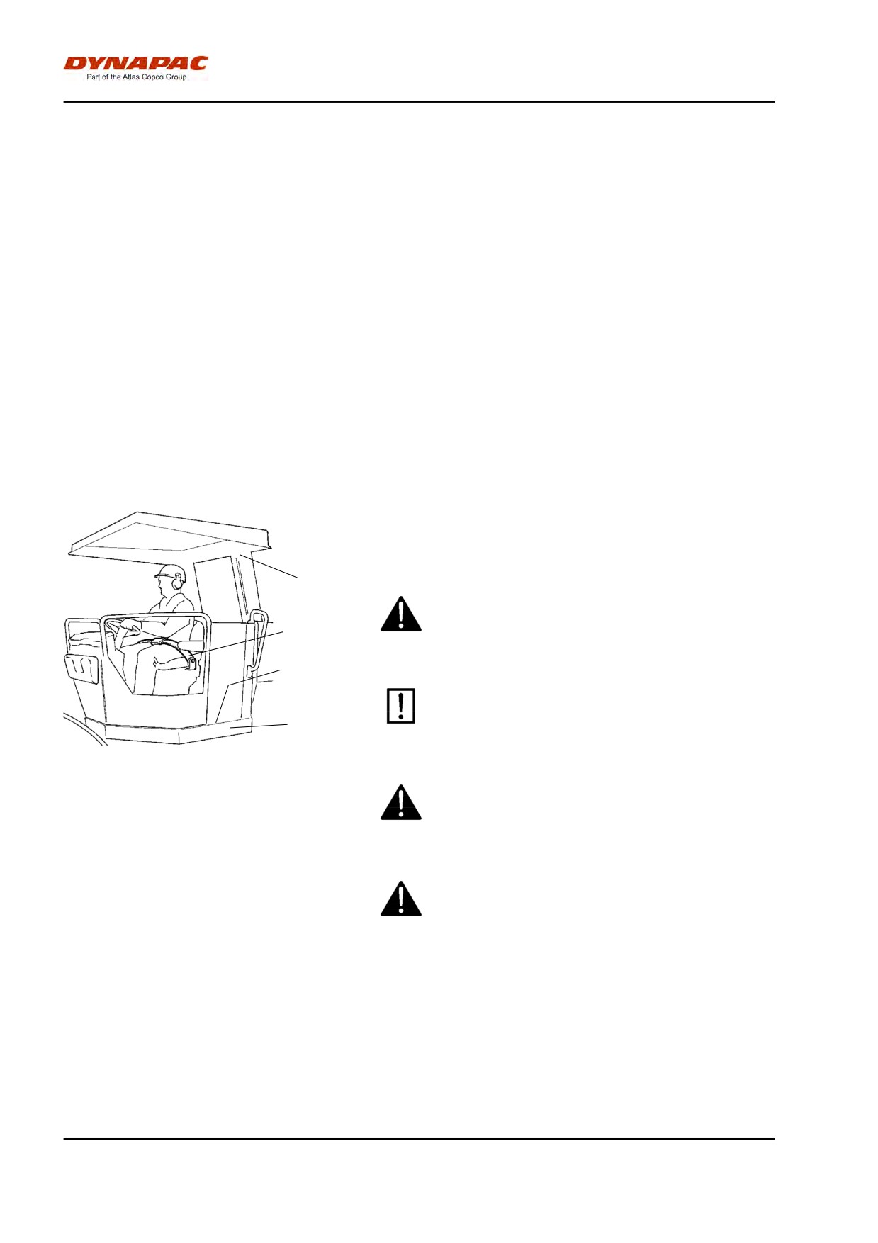
If a ROPS (2) (Roll Over Protective Structure) or a cab
is fitted to the roller, always wear the seat belt (1)
provided and wear a protective helmet.
2
Replace the seat belt (1) if it shows signs of
wear or has been subjected to high levels of
1
force.
4
Check that rubber elements (3) on the platform
are intact. Worn elements will impair comfort.
3
Fig. Operator's station
1. Seat belt
Ensure that the anti-slip (4) on the platform is in
2. ROPS
good condition. Replace where anti-slip friction is
3. Rubber element
poor.
4. Anti-slip
If the machine is fitted with a cab, make sure that
the door is closed when in motion.
48
Operation - Starting
View
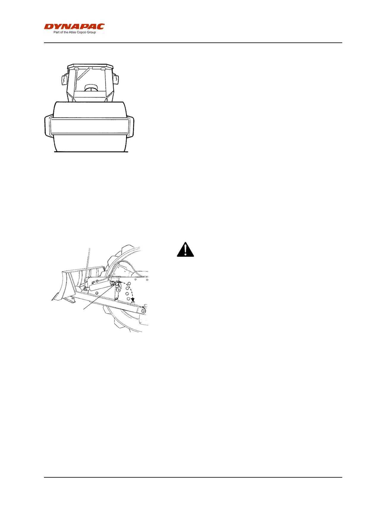
Before starting, make sure that the view forwards and
backwards is unobstructed.
All cab windows should be clean and the rear view
mirrors should be correctly adjusted.
Fig. view
Strike-off blade (Optional)
Always ensure that the strike-off blade is secured
by the locking pin (1) when driving with the blade
in its raised position. Always lower the blade to the
ground before leaving/parking the roller.
1
Fig. Strike-off blade
1. Cotter pin
Starting
49
Operation - Starting
Starting the engine
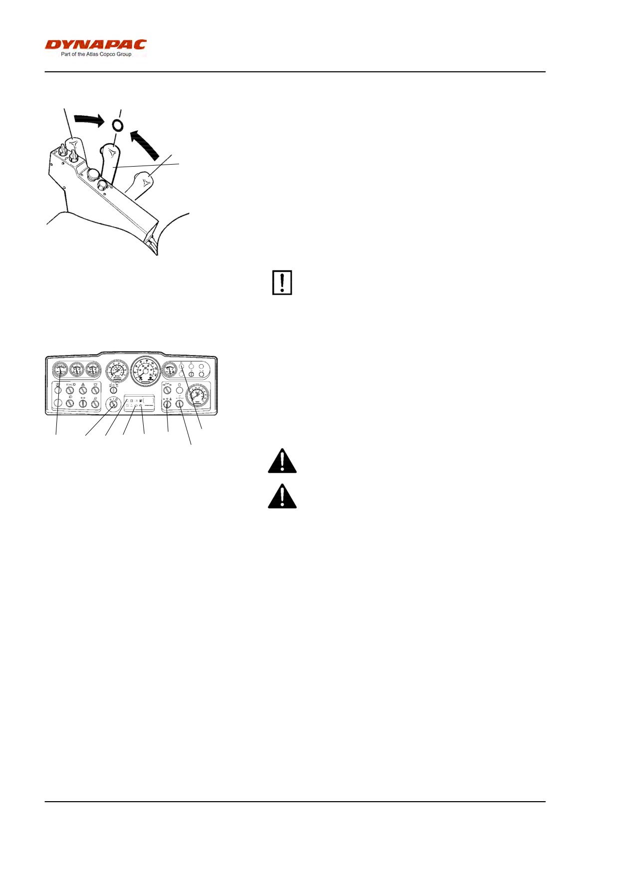
Set the forward/reverse lever (39) in neutral. The
diesel engine cannot be started in any other position
on the control.
39
Set the amplitude selector (24) for Low/High vibration
in position O.
Set the engine speed control (23) in the idling position.
Turn the starter switch (1) to the right to the first
position. The preheating lamp (16) now comes on.
When the lamp goes off, turn the control to the start
position and release as soon as the engine starts. This
Fig. Control panel
particularly important when starting a cold machine.
39. Forward/Reverse lever
Do not run the starter motor for too long. If the
engine does not start immediately, wait a minute
or so before trying again.
Let the engine idle for a few minutes to warm, longer if
the ambient temperature is below +10°C (50°F).
While the engine is warming up, check that the
warning lamps for oil pressure (28) and charging (31)
are not on, and also that the voltmeter (10) shows
13-14 volts. The warning lamp (27) for the parking
16
brake must still be on.
10
1
31 28
27
24
23
Ensue that there is good ventilation (air extraction)
if the engine is run indoors. Risk of carbon
Fig. Instrument panel
monoxide poisoning.
1. Starter switch
When starting up and driving a cold machine,
10. Voltmeter (Optional)
which implies cold hydraulic fluid, the braking
16. Preheating lamp
distance will be longer than normal until the
23. Engine speed control
24. Amplitude selector
machine reaches working temperature.
27. Brake lampa
28. Oil pressure lamp
31. Charging lamp
50
Operation - Driving
Operation - Driving
Operating the roller
Under no circumstances is the machine to be
operated from the ground. The operator must be
seated inside the machine during all operation.
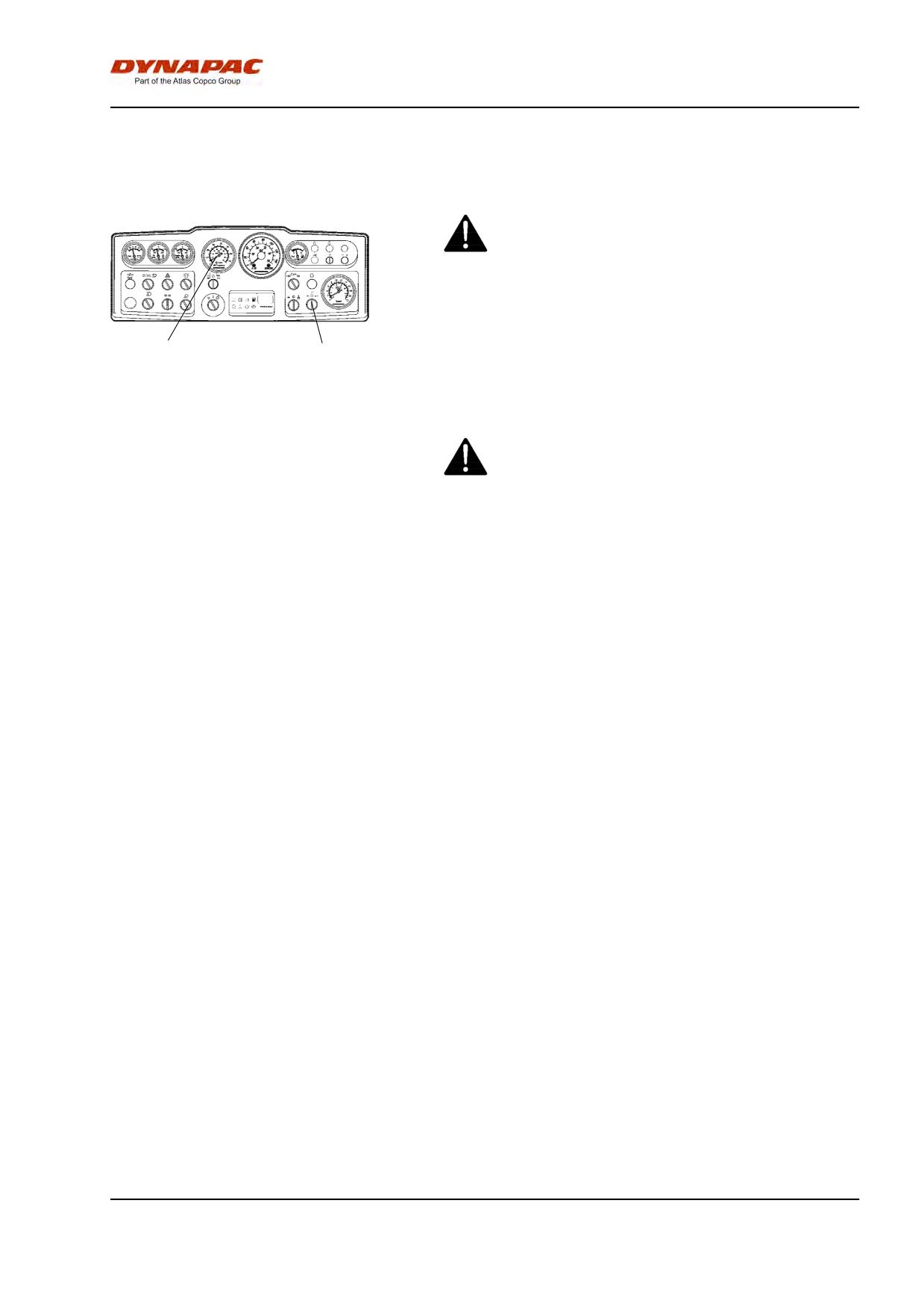
Turn the engine speed control (23) to the position for
13
23
2,200 rpm.
Check that the steering is working correctly by turning
Fig. Instrument panel
the steering wheel once to the right and once to the
13. Tachometer (Optional)
left while the roller is stationary.
23. Engine speed control
Make sure that the area in front of and behind the
roller is clear.
51
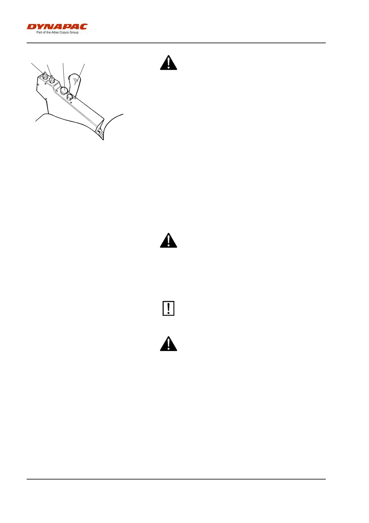
Operation - Driving
35
Pull up the emergency/parking brake knob (37) and
36
37
39
check that the parking brake warning lamp is off.
Remember that the roller can start rolling, if it is on
a slope.
Set the High/Low speed selectors (35) and (36) to the
desired mode, see decal on the control panel.
Maximum speed
Fig. Control panel
Low drum/Low rear axle
5.0 km/h
35. Speed selector, drum/wheels
Low drum/High rear axle
9.0 km/h
(Optional)
* High drum/Low rear axle
6.5 km/h
36. Speed selector, wheels
37. Emergency/Parking brake knob
* High drum/High rear axle
16.0 km/h
39. Forward/Reverse lever
*Only with accessory
The High/High mode may only be used for
transport runs on an even surface.
Carefully move the forward/reverse lever (39) forwards
or backwards, depending on which direction of travel
is required. The speed increases as the lever is moved
away from the neutral position.
The speed should always be controlled using the
forward/reverse lever and never by changing the
engine speed.
Check the emegency brake by depressing the
emergency/parking brake knob (37) while the roller
is slowly moving forward.
52
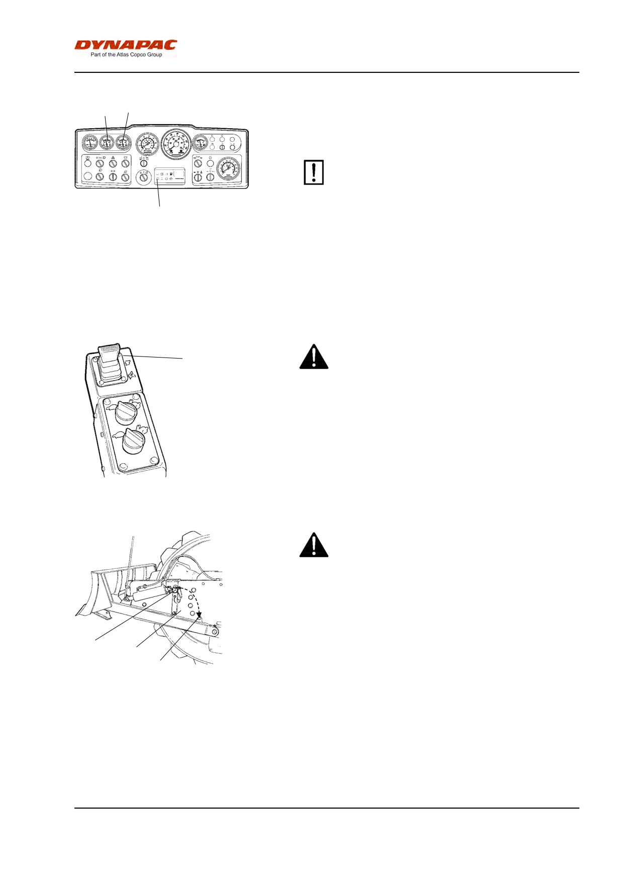
Operation - Driving
11
12
Check while driving that the gauges show normal
readings. In the event of abnormal values or if the
buzzer sounds, immediately stop the roller and the
diesel engine. Check and remedy any fault; see also
the chapter on maintenance and the engine manual.
If the warning lamp for the air filter (30) comes on
during operation (when the diesel engine is
running at full speed), the main filter must be
cleaned or replaced. See the Maintenance
30
Manual.
Fig. Instrument panel
11. Hydraulic oil temperature (Optional)
12. Engine temperature (Optional)
30. Warning lamp, air filter
Operation of strike-off blade (Optional)
Before driving, make certain that the blade is in its
1
uppermost position (raised). Inspect the condition
of the ground before using the blade.
The lever (1) has three positions.
Backward - Raising the blade.
Forward - Lowering the blade.
Forward locked - Float mode, only its own weight
Fig. Controls
presses the blade down.
1. Lever
Lower the blade to the ground before leaving or
parking the roller.
Use the blade only when driving FORWARD.
When using the strike-off blade, the safety link (2)
must be secured with its locking pin in the parking
catch (3).
1
2
3
Fig. Strike-off blade
1. Locking pin
2. Safety link
3. Parking catch
53
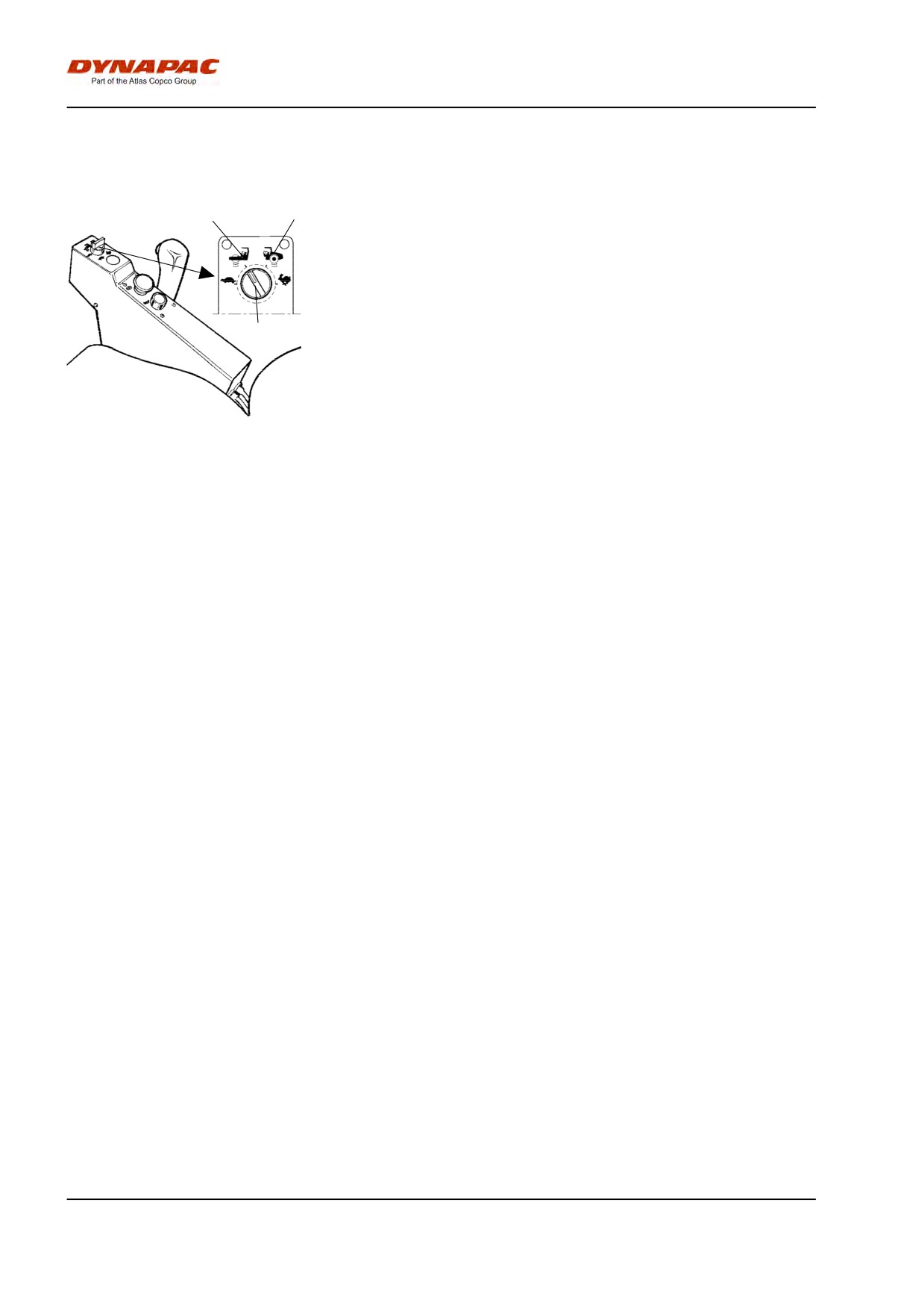
Operation - Driving
Operation on difficult surfaces (Optional)
Drive, drum/wheels
2
3
If the machine should get stuck and it is equipped with
a 2-speed drum drive, set the drive knob as shown
below.
If the drum spins: Turn the knob (35) to Position 2
If the rear tires spin: Turn the knob (35) to Position 3.
35
When the machine has regained its grip set the knobs
in their original positions.
Fig. Control panel
35. Speed selector, drum/wheels
(Optional)
2. Position 2
3. Position 3
54
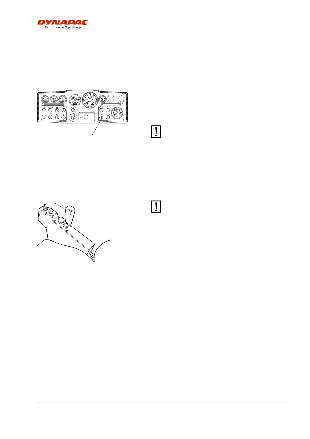
Operation - Vibration
Operation - Vibration
Vibration
Amplitude/frequency - Changeover
There are two drum vibration settings. Use the switch
(24) to adjust.
Turn the knob to the left for low amplitude/high
frequency and to the right for high amplitude/low
frequency.
Setting the amplitude may not be performed
when vibration is in operation.
24
Switch the vibration off first and wait until
vibration stops before setting amplitude.
Fig. Instrument panel
24. Amplitude selector Low/0/High
Manual vibration - Switching on
38
Never activate vibration when the roller is
stationary. This can damage both the surface and
the machine.
Engage and disengage vibration using the switch (38)
on the front of the forward/reverse lever.
Always switch off vibration before the roller comes to a
standstill.
Fig. Control panel
38. Switch, vibration On/Off
The engine does not stop if the parking brake is
activated.
55
Operation - Vibration
56
Operating - Stopping
Operating - Stopping
Braking
Emergency brake
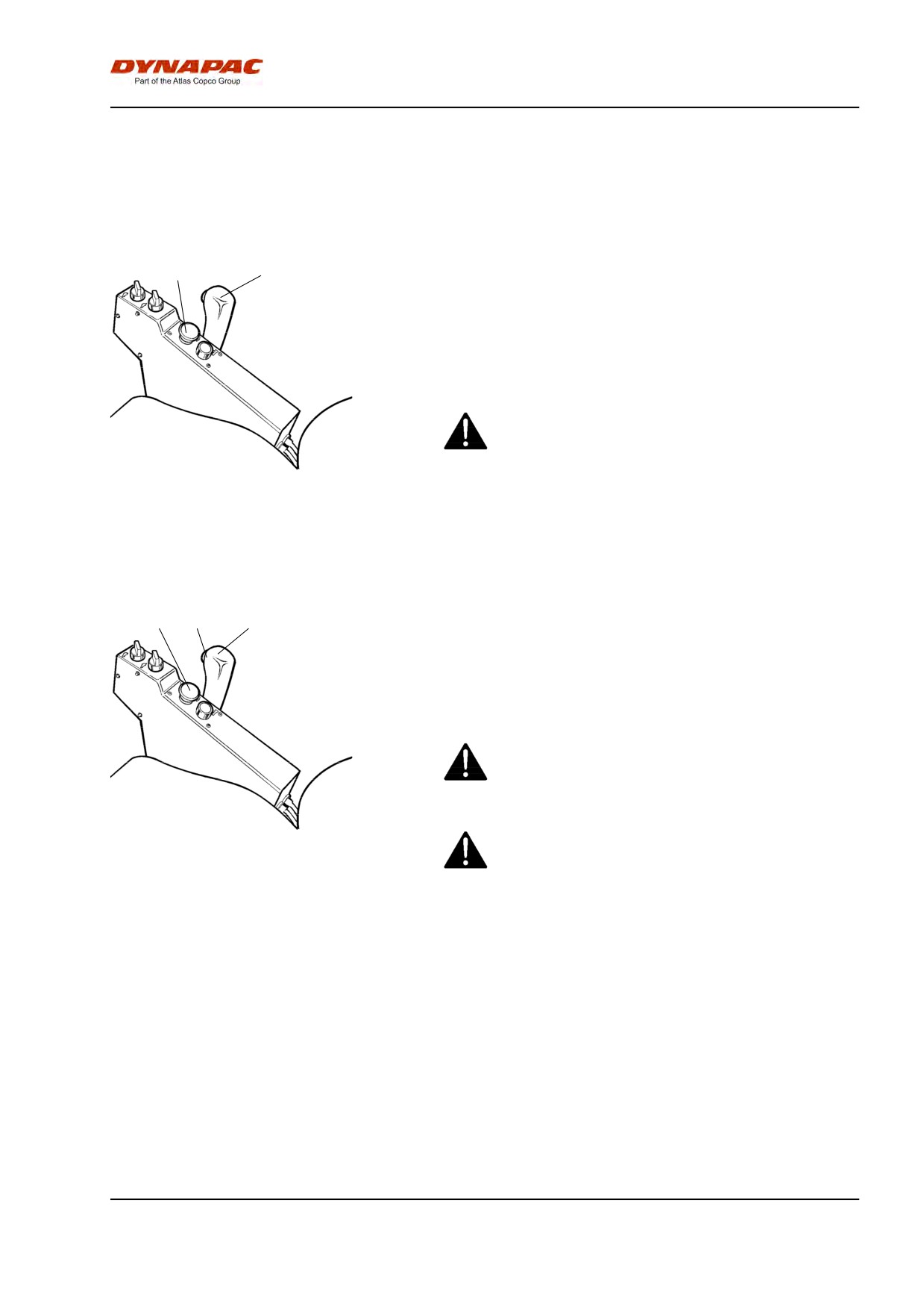
37
39
Braking is normally activated using the
forward/reverse lever. The hydrostatic transmission
retards and slows the roller when the lever is moved
towards the neutral position.
A disc brake in the drum motor and rear axle acts as
an emergency brake when in motion and as a parking
brake when stationary.
To brake, press the reserve/parking brake knob
(37), hold the steering wheel firmly and be
prepared for a sudden stop.
Fig. Control panel
37. Reserve/parking brake knob
39. Forward/Reverse lever
After braking, return the forward/reverse lever to the
neutral position and pull up the emergency/parking
brake knob.
Normal braking
37
38
39
Press the switch (38) to switch off the vibration.
Move the forward/reverse lever (39) to the neutral
position to stop the roller.
Turn the engine speed control back to idling. Allow the
engine to idle for a few minutes to cool down.
When starting and driving a machine that is cold,
remember that the hydraulic fluid is also cold and
that braking distances can be longer than normal
until the machine reaches the working temperature.
Fig. Control panel
37. Reserve/Parking brake knob
Always press the reserve/parking brake knob (37),
38. Switch, vibration On/Off.
39. Forward/Reverse lever
even for brief stops when on sloping ground.
57
Operating - Stopping
Switching off
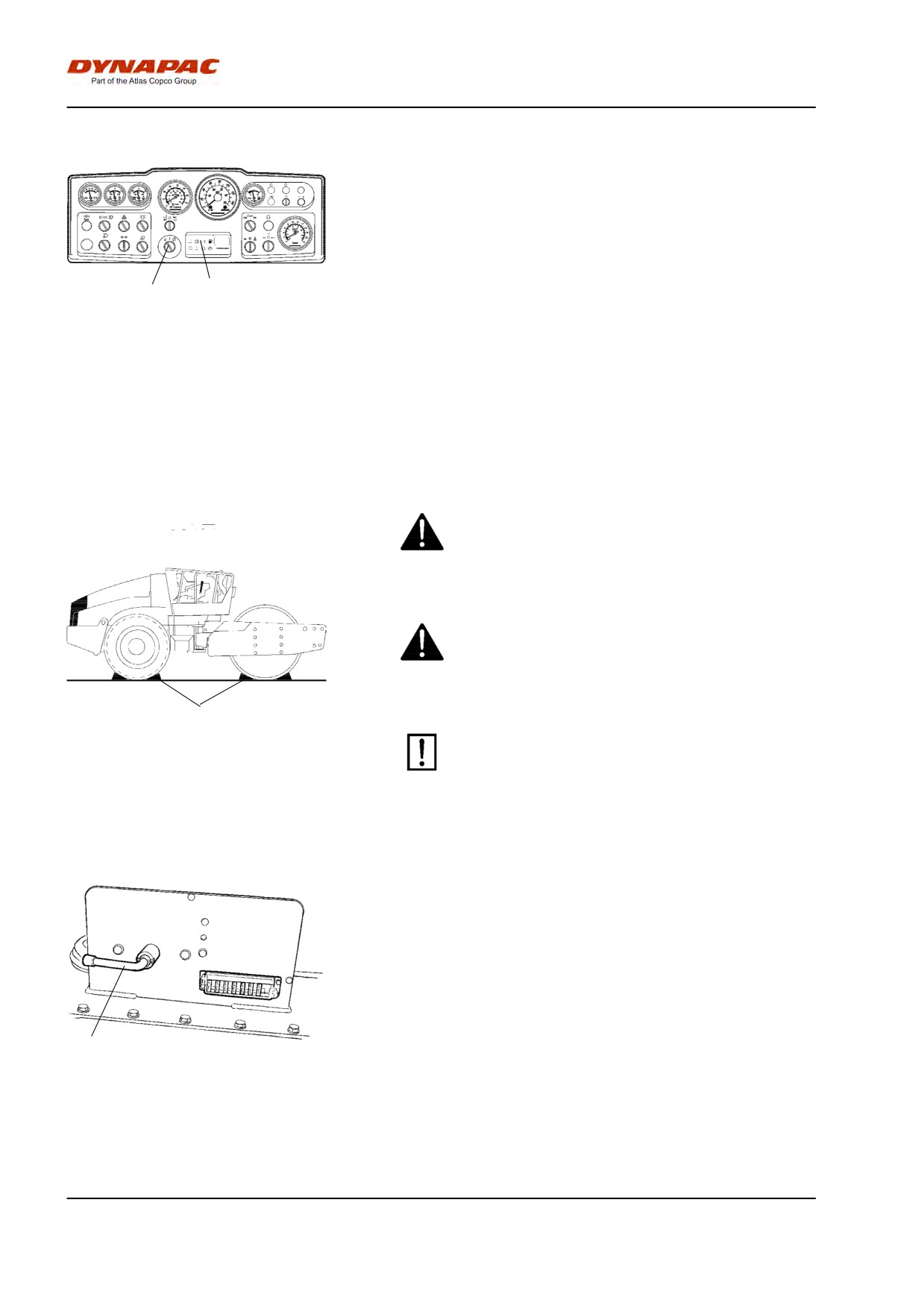
Check instruments and warning lamps to see if any
faults are indicated. Switch off all lights and other
electrical functions.
Turn the starter switch (1) to the left to the shut off
position. On rollers without a cab, lower and lock the
instrument cover.
1
2
Fig. Instrument panel
1. Starter switch
2. Panel for warning lamps
Parking
Chocking the drums
Never disembark from the machine when the is
engine running, unless the emergency/parking
brake knob is depressed.
Make sure that the roller is parked in a safe place
with respect to other road users. Chock the drums
if the roller is parked on sloping ground.
1
Remember the risk of freezing during the winter.
Fig. Arrangement
1. Chock
Fill the engine cooling system and the
screenwash bottle in the cab with suitable
anti-freeze mixtures. See also the maintenance
instructions.
Master switch
Before leaving the roller for the day, switch the master
switch (1) to the disconnected position and remove the
handle.
This will prevent battery discharging and will also
make it difficult for unauthorized persons to start and
operate the machine. Lock the engine compartment
doors.
1
Fig. Tractor frame, rear left
1. Master switch
58
Long-term parking
Long-term parking
The following instructions should be followed
when long term parking (more than one month).
These measures apply when parking for a period of up
to 6 months.
Before re-commissioning the roller, the points marked
with an asterisk * must be returned to the pre-storage
state.
Wash the machine and touch up the paint finish to
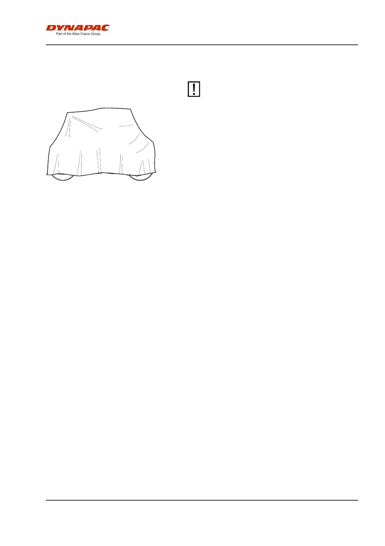
Fig. Roller weather protection
avoid rusting.
Treat exposed parts with anti-rust agent, lubricate the
machine thoroughly and apply grease to unpainted
surfaces.
Engine
* Refer to the manufacturer’s instructions in the engine
manual that is supplied with the roller.
Battery
* Remove the battery from the machine. Clean the
battery, check that the electrolyte level is correct (see
under the heading 'Every 50 hours of operation') and
trickle-charge the battery once a month.
Air cleaner, exhaust pipe
* Cover the air cleaner (see under the heading 'Every
50 hours of operation' or 'Every 1000 hours of
operation') or its opening with plastic or tape. Also
cover the exhaust pipe opening. This is to avoid
moisture entering the engine.
Fuel tank
Fill the fuel tank completely full to prevent
condensation.
Hydraulic reservoir
Fill the hydraulic reservoir to the uppermost level mark
(see under the heading ‘Every 10 hours of operation.’)
Tires (All-weather)
Check that tire pressure is 110 kPa (1.1 kp/cm 2 ), (16
psi).
59
Long-term parking
Steering cylinder, hinges, etc.
Lubricate the articulation bearing with grease (see
under the heading "Every 50 hours of operation").
Grease the steering cylinder piston with conservation
grease.
Grease the hinges on the doors to the engine
compartment and the cab. Grease both ends of the
forward/reverse control (bright parts) (see under the
heading 'Every 500 hours of operation').
Hoods, tarpaulin
* Lower the instrument cover over the instrument
panel.
* Cover the entire roller with a tarpaulin. A gap must
be left between the tarpaulin and the ground.
* If possible, store the roller indoors and ideally in a
building where the temperature is constant.
60
Miscellaneous
Miscellaneous
Lifting
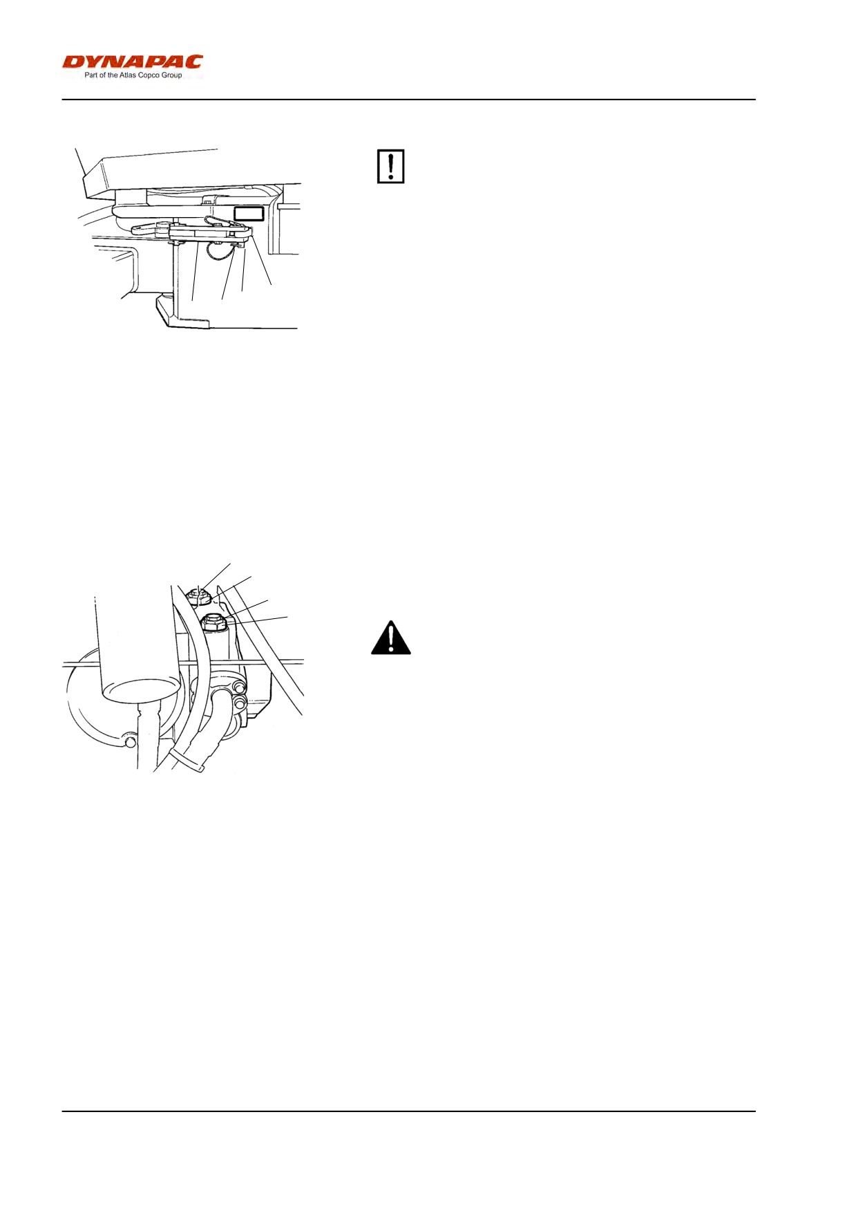
Locking the articulation
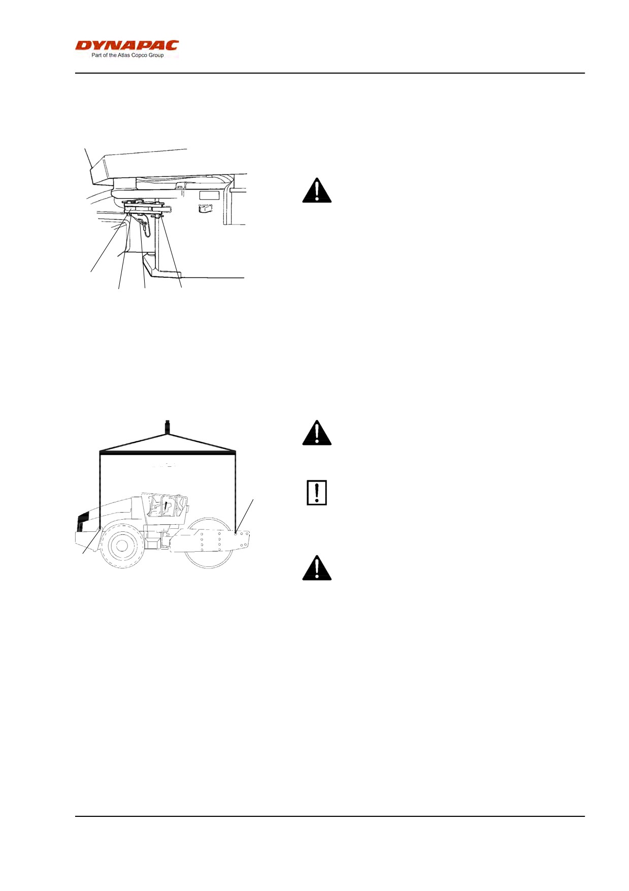
Articulation must be locked to prevent inadvertent
turning before lifting the roller.
Turn the steering wheel to the straight ahead position.
Push in the emergency/parking brake knob.
4
Pull out the lowermost locking pin (2), which has a a
3
2
1
wire attached. Pull up the locking dowel (3) which also
has a wire attached.
Fig. Articulation in the locked position
1. Locking arm
2. Locking pin
Fold out the locking arm (1) and secure it to the upper
3. Locking stud
locking lug (4) on steering joint.
4. Locking lug
Fit the locking stub (3) in the holes through the locking
arm (1) and locking lug (4) and secure the stud in
position with the locking pin (2).
Weight: refer to the hoisting plate on the
roller
Lifting the roller
The machine’s gross weight is specified on the
hoisting plate (1). Refer also to the Technical
specifications.
Lifting equipment such as chains, steel wires,
1
straps and lifting hooks must be dimensioned in
accordance with the relevant safety regulations
for the lifting equipment.
1
Stand well clear of the hoisted machine! Make sure
that the lifting hooks are properly secured.
Fig. Roller prepared for lifting
1. Hoisting plate
61
Miscellaneous
Unlocking the articulation
Remember to unlock the articulation before
operating.
Fold the locking arm (1) back and secure it in the
locking lug (4) with the locking stud (3). Insert the
lowermost locking pin (2) fitted with a wire, to secure
4
the locking stud (3). The locking lug (4) is located on
3
1
2
the tractor frame.
Fig. Articulation in the open position
1. Locking arm
2. Locking pin
3. Locking stud
4. Locking lug
Towing
The roller can be moved up to 300 meters (1,000 ft)
using the instructions below.
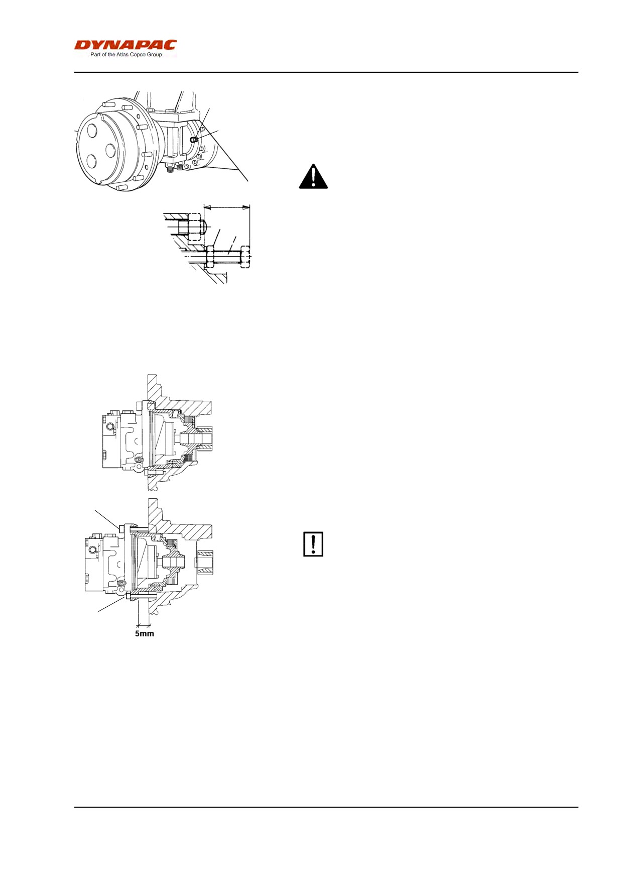
1
Alternative 1
2
1
Short distance towing with the engine running
2
Depress the emergency/parking brake knob and
temporarily shut off the engine. Chock the drums
to prevent the roller from moving
Turn both towing valves (1) (middle hexagonal nut)
three turns counter clockwise, while holding the
multifunction valve (2) (lowermost hexagonal nut) in
Fig. Propulsion pump
place. The valves are placed on the forward drive
1. Towing valve
2. Locknut
pump.
Start the engine and allow it to idle.
The roller can now be towed and can also be steered
if the steering system is otherwise functioning.
62
Miscellaneous
4
Alternative 2
3
Towing short distances where the engine is
inoperative
Chock the drums to prevent the roller from moving
when the brakes are mechanically disengaged.
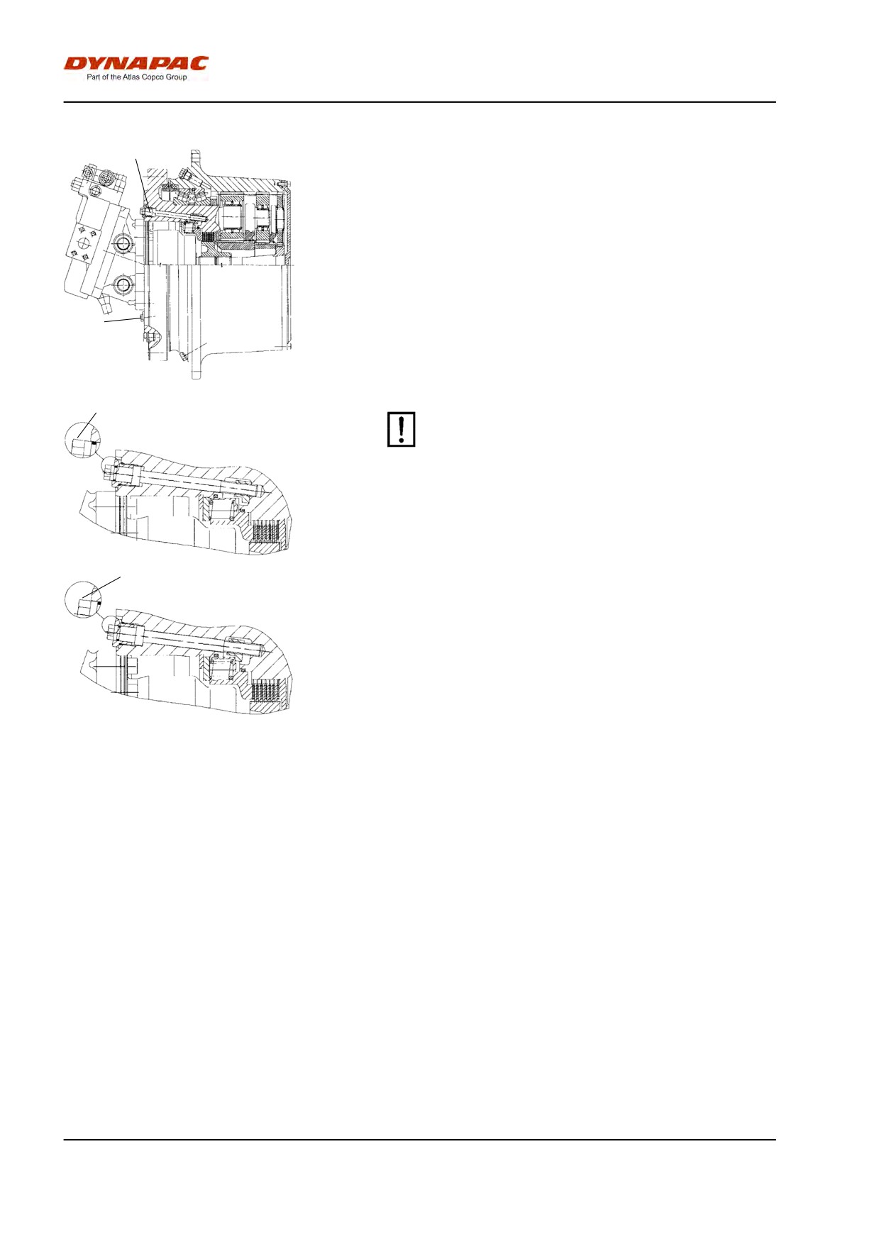
34 mm
3
4
First release both towing valves as per alternative 1.
Fig. Rear axle
3. Locknut
4. Adjusting screw
Rear axle brake
Undo the lock nut (3) and screw the adjustment
screws (4) by hand until resistance increases, and
then one additional turn. The adjustment screws are
located on the rear axle, two screws on each side of
the differential housing.
Drum gearbox brake
The drum brake is disengaged by screwing out the 4
hexagonal socket screws (5) approx. 5 mm, and then
pulling out the engine adapter towards the screw
heads.
The brakes are now disengaged and the roller can be
towed.
5
After towing, remember to reset the towing valves
(1). Unscrew the adjusting screw (4) to its original
position 34 mm from the contact surface and
tighten the lock nuts (3). Tighten the four
hexagonal socket screws (5). See section "short
distance towing" alternative 1 and 2.
5
Fig. Drum brake
5. Screw
63
Miscellaneous
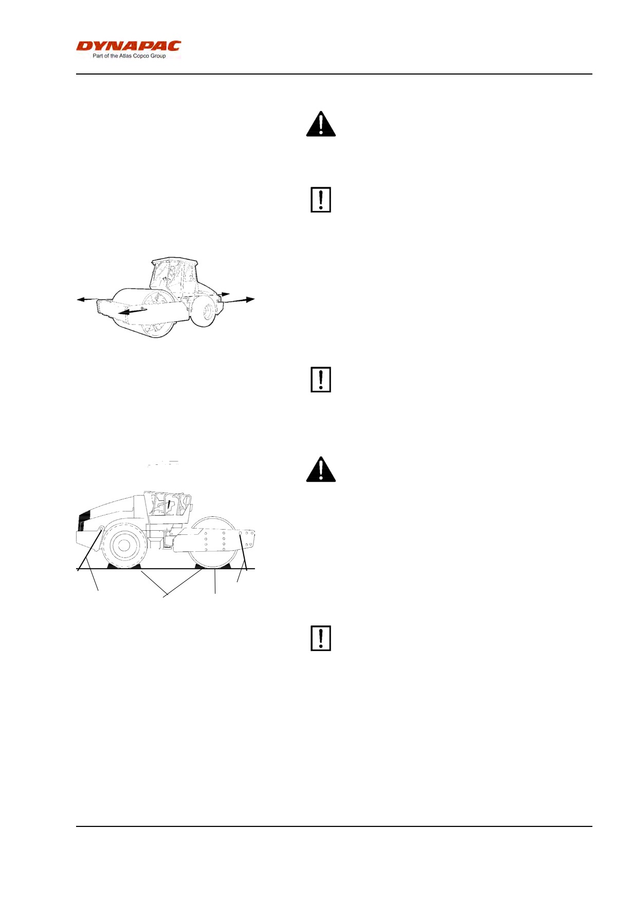
5
Drum gearbox brake (Option)
Disengage the drum brake by screwing in the two
screws (5) until they stop.
Screw in each screw equally, alternating between the
two. This is necessary to prevent jamming the brake
piston.
5
The brakes are now disengaged and the roller can be
towed.
5
After towing, don't forget to reset the towing
valves (1), Screw out the adjustment screw (4) to
its original position 34 mm from the stop surface,
and tighten the locking nuts (3). Loosen the drum
brake screws (5). See the section "Short distance
towing" options 1 and 2.
5
Fig. Drum brake
5. Screw
64
Miscellaneous
Towing the roller
When towing/recovering, the roller must be braked
by the towing vehicle. A towing bar must be used
as the roller has no brakes.
The roller must be towed slowly, max. 3 km/h (2
mph) and only towed short distances, max. 300 m
(330 yards).
When towing/retrieving a machine, the towing device
must be connected to both lifting holes. The pulling
force must act longitudinally on the machine as shown
in the figure. Maximum gross pulling force 200 kN
(44961 lbf).
Fig.Towing
Restore the items for towing according to
alternative 1 or 2 on the preceding pages.
Roller prepared for transport
Lock the articulation before lifting and
transporting. Follow the instructions under the
relevant heading.
Chock the drums (1) and secure the chocks to the
transport vehicle.
Block up under the drum frame (2), to avoid overload
on the rubber suspension of the drum when lashing.
3
3
2
Clamp down the roller with lashing strap at all four
1
corners; decals (3) indicate the fixing points.
Fig. Transport
1. Chock
Remember to return the articulation to its
2. Block up
unlocked position before starting the roller.
3. Lashing wire
65
Operating instructions - Summary
66
Operating instructions - Summary
Operating instructions - Summary
1.
Follow the SAFETY INSTRUCTIONS specified in the Safety Manual.
2.
Make sure that all instructions in the MAINTENANCE section are followed.
3.
Turn the master switch to the ON position.
4.
Move the forward/reverse lever to the NEUTRAL position.
5.
Set the switch for Manual/Automatic vibration to the 0 position.
6.
Set the engine speed control to idle (900 rpm).
7.
Start the engine and allow it to warm up.
8.
Set the engine speed control to the operating position (2,200 rpm).
9.
Set the emergency/parking brake knob in the pulled-out position.
10. Drive the roller. Operate the forward/reverse lever with care.
11. Test the brakes. Remember that the braking distance will be longer if the
roller is cold.
12. Use vibration only when the roller is in motion.
13. IN AN EMERGENCY:
- Push in the EMERGENCY/PARKING BRAKE KNOB
- Hold the steering wheel firmly.
- Brace yourself for a sudden stop.
14. When parking:
- Push in the reserve/parking brake knob.
- Stop the engine and chock the drum and wheels.
15. When lifting: - Refer to the relevant section in the Instruction Manual.
16. When towing: - Refer to the relevant section in the Instruction Manual.
17. When transporting: - Refer to the relevant section in the Instruction Manual.
18. When recovering - Refer to the relevant section in the Instruction Manual.
67
Operating instructions - Summary
68
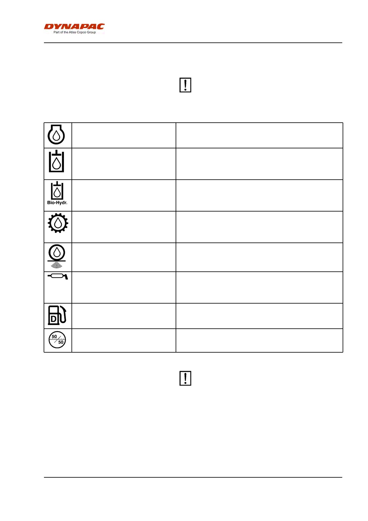
Maintenance - Lubricants and symbols
Maintenance - Lubricants and symbols
Always use high-quality lubricants and the
amounts recommended. Too much grease or
oil can cause overheating, resulting in rapid
wear.
ENGINE OIL
Air temperature -15°C - +50°C (5°F-122°F)
Shell Rimula Super 15W/40, API CH-4 or equivalent.
HYDRAULIC FLUID
Air temperature -15°C-+40°C (5°F-104°F)
Shell Tellus TX68 or equivalent.
Air temperature above +40°C (104°F)
Shell Tellus T100 or equivalent.
BIOLOGICAL HYDRAULIC
BP Biohyd SE-S46
FLUID
When it leaves the factory, the machine may be
filled with biodegradable fluid. The same type of fluid
must be used when changing or topping up.
TRANSMISSION OIL
Air temperature -15°C - +40°C (5°F-104°F)
Shell Spirax AX 80W/90, API GL-5 or equivalent.
Air temperature 0°C (32°F) - above +40°C (104°F)
Shell Spirax AX 85W/140, API GL-5 or equivalent.
DRUM OIL
Mobil SHC 629
GREASE
SKF LGHB2 (NLGI-Klass 2) or equivalent for the
articulated joint.
Shell Retinax LX2 or equivalent for other grease
points.
FUEL
See engine manual.
COOLANT
GlycoShell or equivalent, (mixed 50/50 with water).
Anti-freeze protection down to about -37°C (-34.6°F).
Other fuel and lubricants are required when
operating in areas with extremely high or
extremely low ambient temperatures. See the
‘Special instructions’ chapter, or consult
Dynapac.
69
Maintenance - Lubricants and symbols
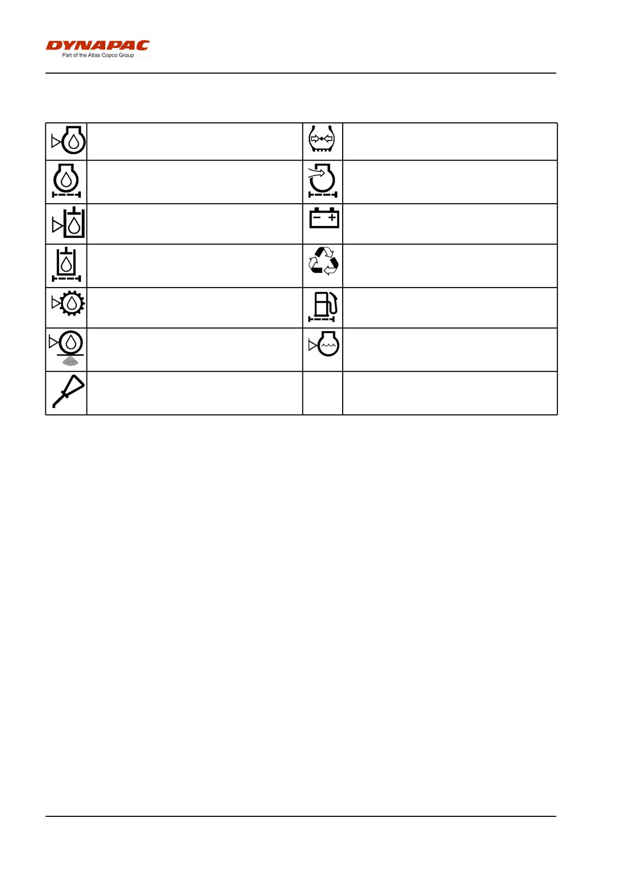
Maintenance symbols
Engine, oil level
Tyre pressure
Engine, oil filter
Air filter
Hydraulic reservoir, level
Battery
Hydraulic fluid, filter
Recycling
Transmission, oil level
Fuel filter
Drum, oil level
Coolant, level
Oil for lubrication
70
Maintenance - Maintenance schedule
Maintenance - Maintenance schedule
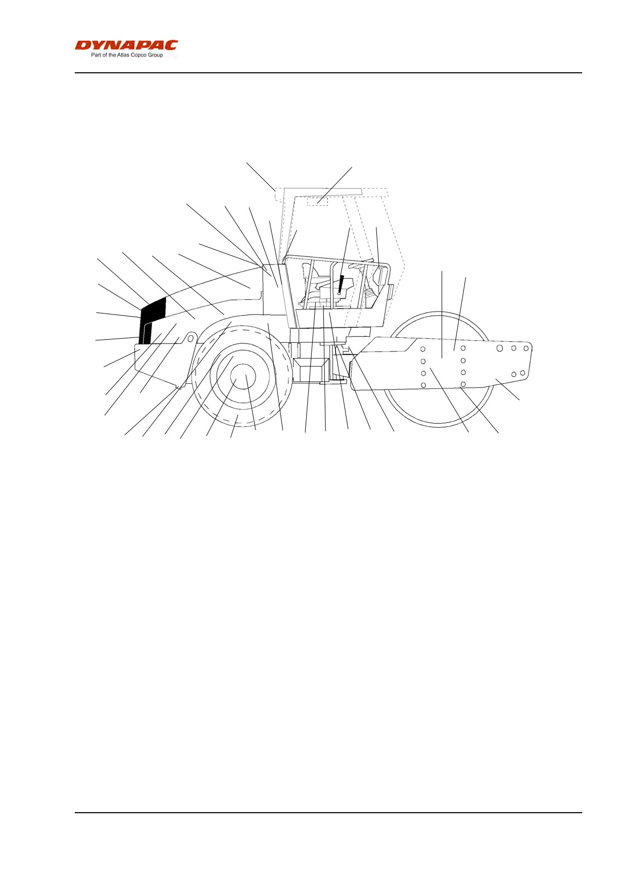
Service and maintenance points
39
38
6
7
8
9
11
10
37
4
5
1
2
3
12
13
33
32
31
30
29
27
14
28
22
20
19
35
34
17
18
16
15
26
25
24
23
21
36
Fig. Service and maintenance points
1.
Radiator grille
14. Scrapers
27. Engine suspension, 4 pcs.
2.
Oil level, diesel engine
15. Drum oil, level plug, x2
28. Feed pump, fuel
3.
Fuel filter, fuel pre-filter
16. Rubber elements and fastening
29. Diesel fuel, filler
screws
4.
Air filter
17. Steering joint
30. Battery
5.
Engine cover, hinges
18. Steering cylinders, x2
31. Radiator
6.
Hydraulic reservoir, sight glass
19. Flywheel casing, hydraulic
32. Hydraulic fluid cooler
pumps
7.
Bleeding filter
20. Wheel nuts
33. Drive belts, cooling, alternator
8.
Hydraulic filter, 2 pcs.
21. Tires, pressure
34. Steering chain
9.
Drainage, hydraulic fluid
22. Rear axle, differential
35. Seat bearing
reservoir
10. Hydraulic fluid, filling
23. Rear axle, planetary gears, 2
36. Steering chain
pcs.
11. Fuse box
24. Rear axle suspension, 2 sides
37. Forward/reverse lever
12. Drum cartridge, filling, 2 fillers
25. Oil filter, diesel engine
38. Fresh air filter *
13. Drum gearbox
26. Drainage, fuel tank
39. Air conditioning *
* Optional equipment
General
Periodic maintenance should be carried out after the
number of hours specified. Use the daily, weekly etc.
periods where number of hours cannot be used.
71
Maintenance - Maintenance schedule
Remove all dirt before filling, when checking
oils and fuel and when lubricating using oil or
grease.
The manufacturer’s instructions found in the
engine manual also apply.
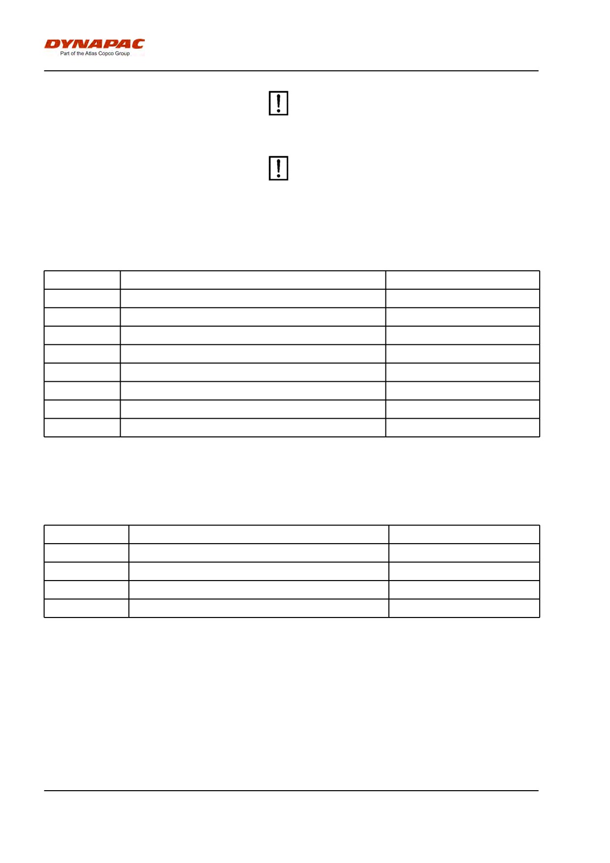
Every 10 hours of operation (Daily)
Refer to the contents to find the page number of the
sections referred to !
Pos. in fig
Action
Comment
Before starting up for the first time on that day
14
Check the scraper setting
1
Check for free circulation of cooling air
31
Check coolant level
Refer to the engine manual
2
Check the engine oil level
Refer to the engine manual
29
Refuel
6
Check fluid level in hydraulic reservoir
Test the brakes
After the FIRST 50 hours of operation
Refer to the contents to find the page number of the
sections referred to !
Pos. in fig
Action
Comment
2
Change the engine oil and oil filter
Refer to the engine manual
3
Change the fuel filter
Refer to the engine manual
8
Change the hydraulic fluid filter
12
Change the drum oil
72

Maintenance - Maintenance schedule
Every 50 hours of operation (Weekly)
Refer to the contents to find the page number of the
sections referred to!
Pos.
Action
Comment
in fig
Check that hoses and couplings are not leaking
4
Inspect/clean the filter element in the air cleaner
Replace as required
17
Lubricate the articulation
20
Check the wheel-nuts are tightened
21
Check the tire pressure
39
Check the air conditioning
Optional
Lubricate the strike-off blade bearings.
Optional
Every 250 hours of operation (Monthly)
Refer to the contents to find the page number of the
sections referred to !
Pos. in fig
Action
Comment
23
Check oil level in rear axle/planetary gearing
13
Check oil level in drum gearbox
15
Check oil level in the drum cartridge
32
Clean the coolers
20
Check the bolted joints
The above applies to new
or reconditioned
components only
24
Check the bolted joints
The above applies to new
or reconditioned
components only
16
Check rubber elements and bolted joints
30
Check battery
39
Check the AC
Optional
73
Maintenance - Maintenance schedule
Every 500 hours of operation (Every three
months)
Refer to the contents to find the page number of the
sections referred to !
Pos. in fig
Action
Comment
3
Replace the fuel filter
Refer to the engine manual
5
Lubricate controls and joints
3
Clean the fuel pre-filter.
25
Change the engine oil and oil filter
Refer to the engine manual
36
Grease the steering chain
Optional
35
Grease the chair bearing
Optional
Every 1000 hours of operation (Every six
months)
Refer to the contents to find the page number of the
sections referred to !
Pos. in fig
Action
Comment
7
Check bleeder filter on hydraulic reservoir
8
Change the hydraulic fluid filter
9
Drain the condensate from hydraulic reservoir
26
Drain condensate from fuel tank
4
Replace the main filter in the air cleaner
22
Change oil in rear axle differential
23
Change oil in the rear axle planetary gearing
38
Replace the fresh air filter in the cab
Optional
Check engine valve clearances
Refer to the engine manual
33
Check belt tension in the drive belt system
Refer to the engine manual
74
Maintenance - Maintenance schedule
Every 2000 hours of operation (Yearly)
Refer to the contents to find the page number of the
sections referred to !
Pos. in fig
Action
Comment
9
Change the hydraulic fluid
10
Change the hydraulic fluid
12
Change the oil in the drum cartridge
15
Change the oil in the drum cartridge
13
Change the oil in the drum gearbox
37
Lubricate the Forward/Reverse lever
17
Checking the steering hitch
39
Overhaul air conditioning
Optional
75
Maintenance - Maintenance schedule
76
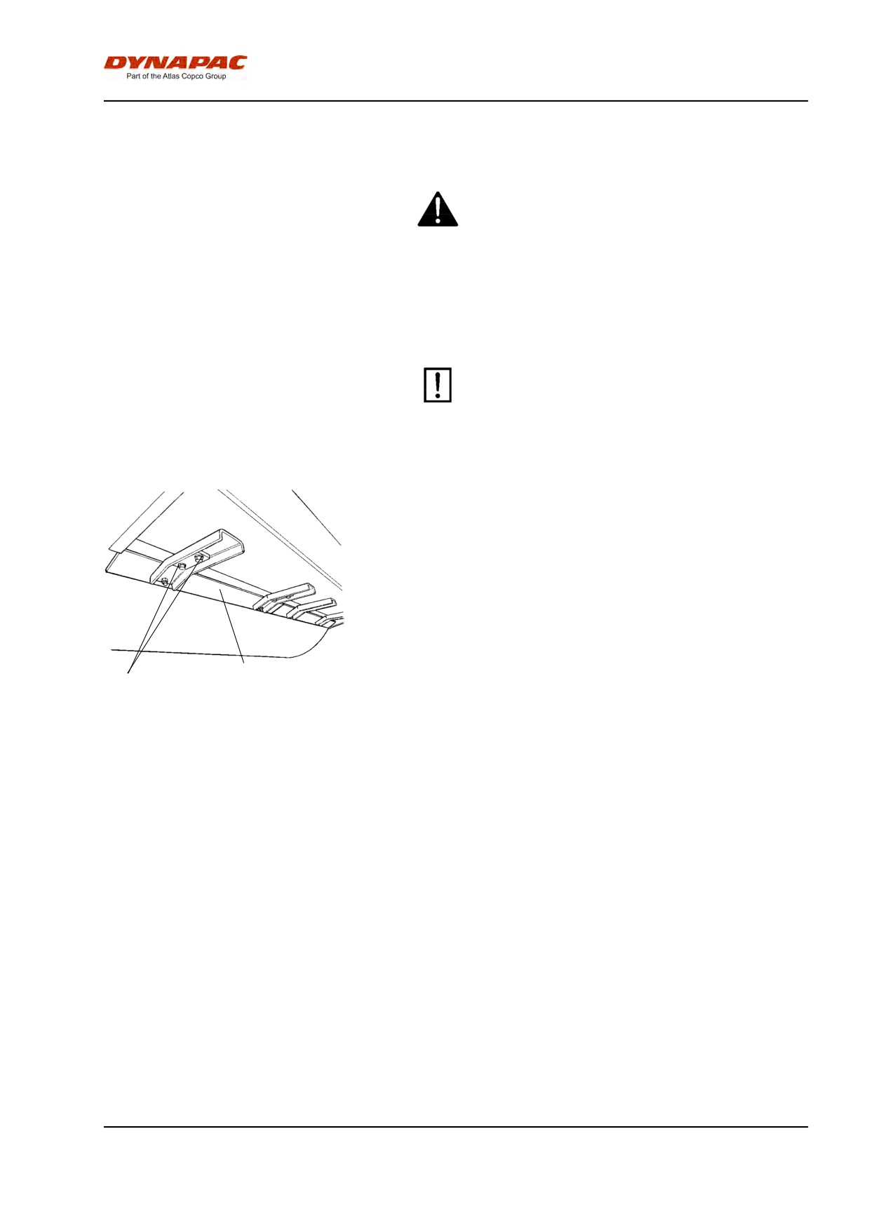
Maintenance - 10h
Maintenance - 10h
Park the roller on a level surface.
When checking and making adjustments, the
engine should be switched off and the
emergency/parking brake should be applied, if
not otherwise specified.
Scrapers - Check, adjustment
It is important to consider movement of the drum
when the machine turns, i.e., the scrapers can be
damaged or wear of the drum may increase if
adjustment is made closer than the values stated.
If necessary, adjust distance to the drum as follows:
Loosen the screws (2) on the scraper attachment.
Then adjust the scraper blade (1) to 20 mm from the
drum.
Tighten the screws (2).
Repeat the procedure for the other scraper blades (x4).
2
1
Fig. Scrapers
1. Scraper blades (x4)
2. Screws
77
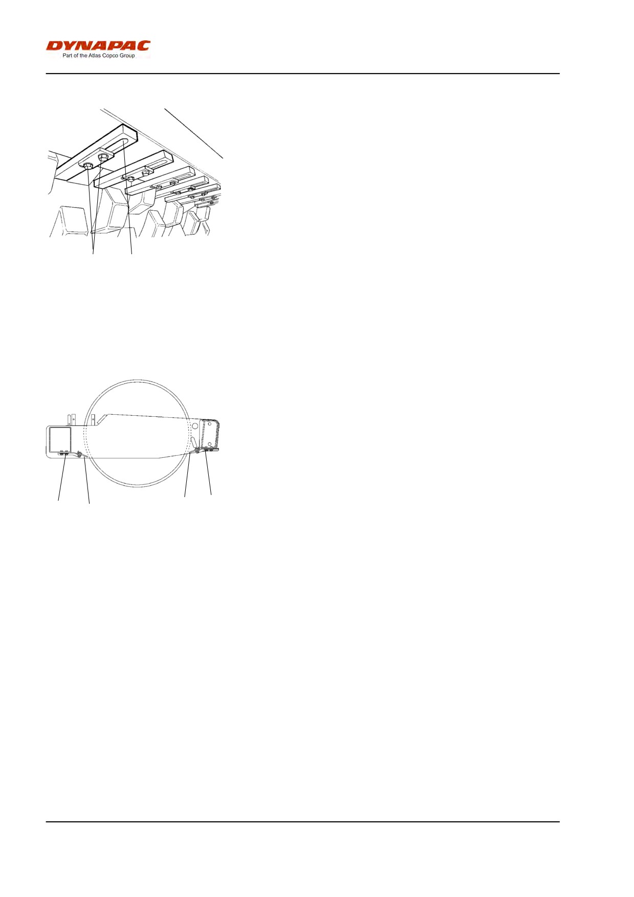
Maintenance - 10h
Scrapers, Pad-drum
Undo the screws (1), then adjust each scraper tooth
(2) to 25 mm (1.0 in) between scraper tooth and drum.
Center each scraper tooth (2) between the pads.
Tighten the screws (1).
1
2
Fig. Scrapers
1. Screws
2. Scraper teeth (x18)
Soften scrapers (Optional)
Loosen the screws (2).
Then, adjust the scraper blade (1) so that it lightly
touches the drum.
Tighten the screws (2).
2
1
2
1
Fig. Scrapers
1. Scraper blade
2. Screws
78
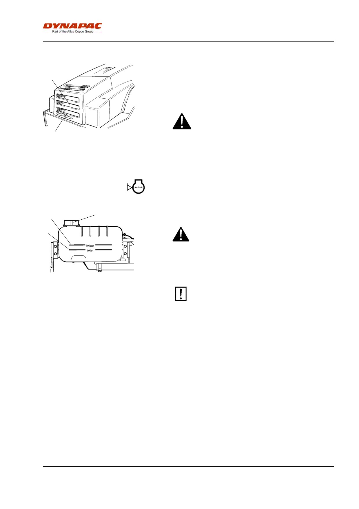
Maintenance - 10h
Air circulation - Check
Ensure that the engine has free circulation of cooling
2
air through the protective grille in the hood.
To open the engine hood, turn the locking arm (1)
upward. Raise the hood to its fully open position,
checking that the red safety catch on the left gas
spring is latched.
If the engine's gas-springs are out of action and
the hood is put at its upper position - block the
hood so that it cannot fall.
1
Fig. Engine hood
1. Hood lock
2. Protective grille
Coolant level - Check
1
3
Check that level of the coolant is between the max.
and min. marks.
Take great caution if the radiator cap must be
2
opened while the engine is hot. Wear protective
gloves and goggles.
Fill with a mixture of 50% water and 50% anti freeze.
See the lubrication specifications in these instructions
and in the engine manual.
Flush the system every other year and change
Fig. Water tank
1. Max. level
the coolant. Make sure also that the air flow
2. Min. level
through the cooler is unobstructed.
3. Filler cap
79
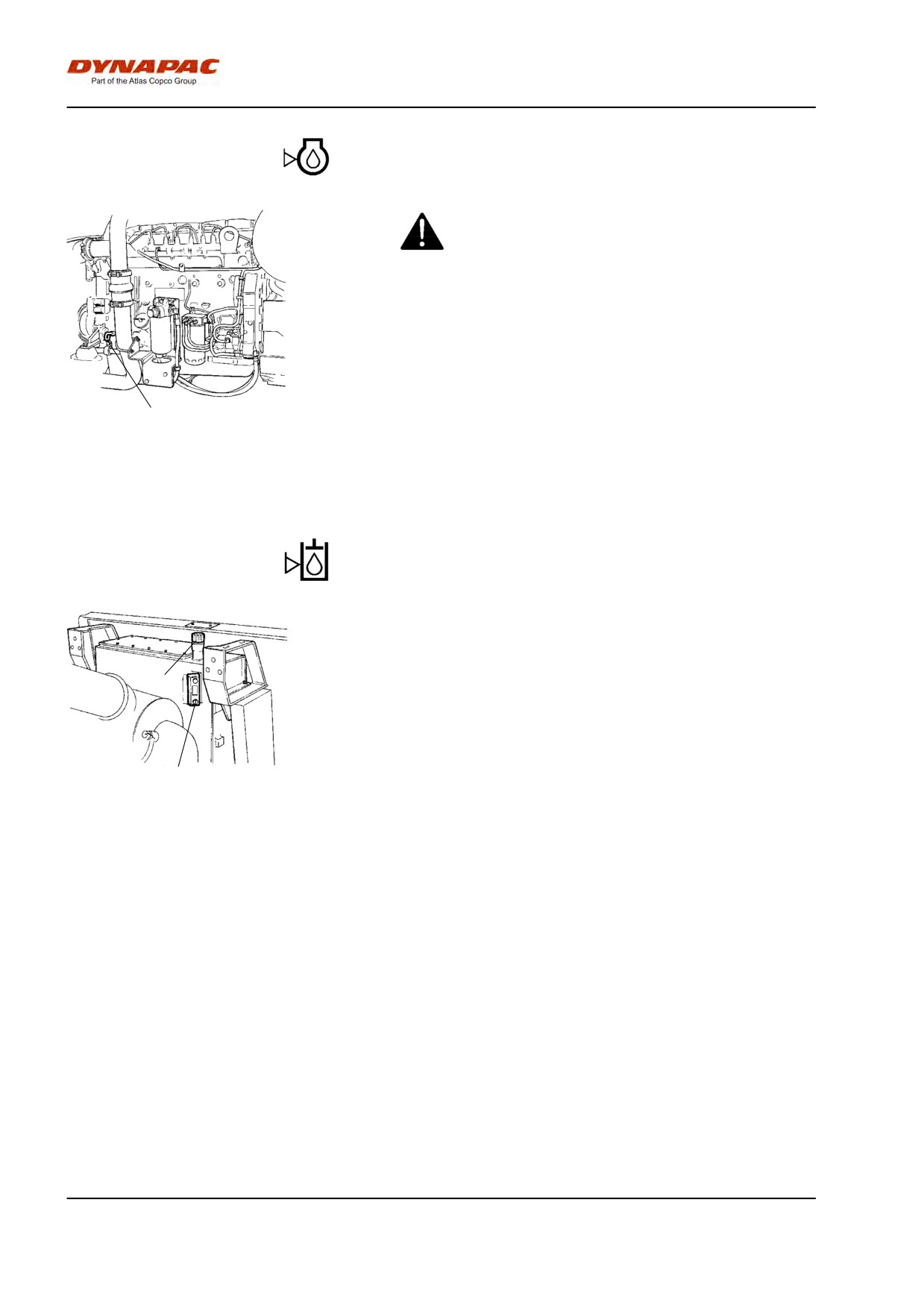
Maintenance - 10h
Diesel engine Check oil level
Take care not to touch any hot parts of the engine
or the radiator when removing the dipstick. Risk
for burns.
The dipstick is located on the engine's right side.
Pull up the dipstick (1) and check that the oil level is
between the upper and lower marks. For further
details, refer to the engine's instruction manual.
1
Fig. Engine compartment
1. Dipstick
Hydraulic reservoir - Check fluid level
Place the roller on a level surface and check that the
oil level in the sight glass (1) is between the max and
min markings. Top up with the type of hydraulic fluid
2
specified in the lubricant specification, if the level is too
low.
1
Fig. Hydraulic reservoir
1. Sight glass
2. Filler pipe
80
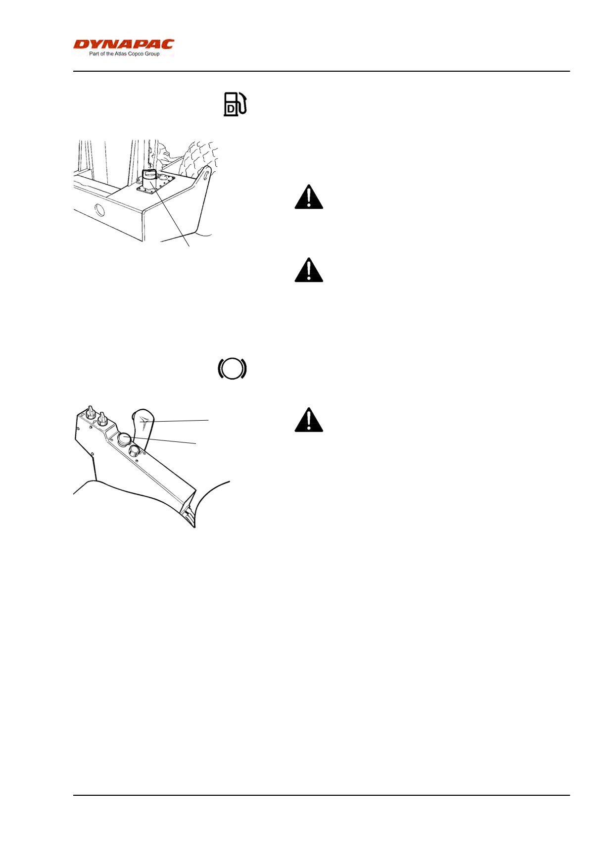
Maintenance - 10h
Fuel tank - Filling
Refuel daily with diesel fuel up to the lower edge of the
filler pipe (1). Follow the engine manufacturer's
specification with regard to the quality of diesel fuel.
Stop the engine. Short-circuit (press) the filler gun
against a non-insulated part of the roller before
refuelling, and against the filler pipe (1) while
refuelling.
1
Never refuel while the engine is running. Do not
smoke and avoid spilling fuel.
Fig. Fuel tank
1. Filler pipe
The tank holds 320 liters (84.5 gal) of fuel.
Brakes - Check
Check the brakes by carrying out the following :
2
1
Drive the roller slowly forwards.
Depress the emergency/parking brake knob (1). The
warning lamp on the instrument panel should come on
and the roller should stop.
After testing the brakes, set the forward/reverse lever
Fig. Control panel
1. Emergency/parking brake knob
(2) in neutral.
2. Forward/reverse lever
Pull up the emergency/parking brake knob.
The roller is now ready for operation.
81
Maintenance - 10h
82
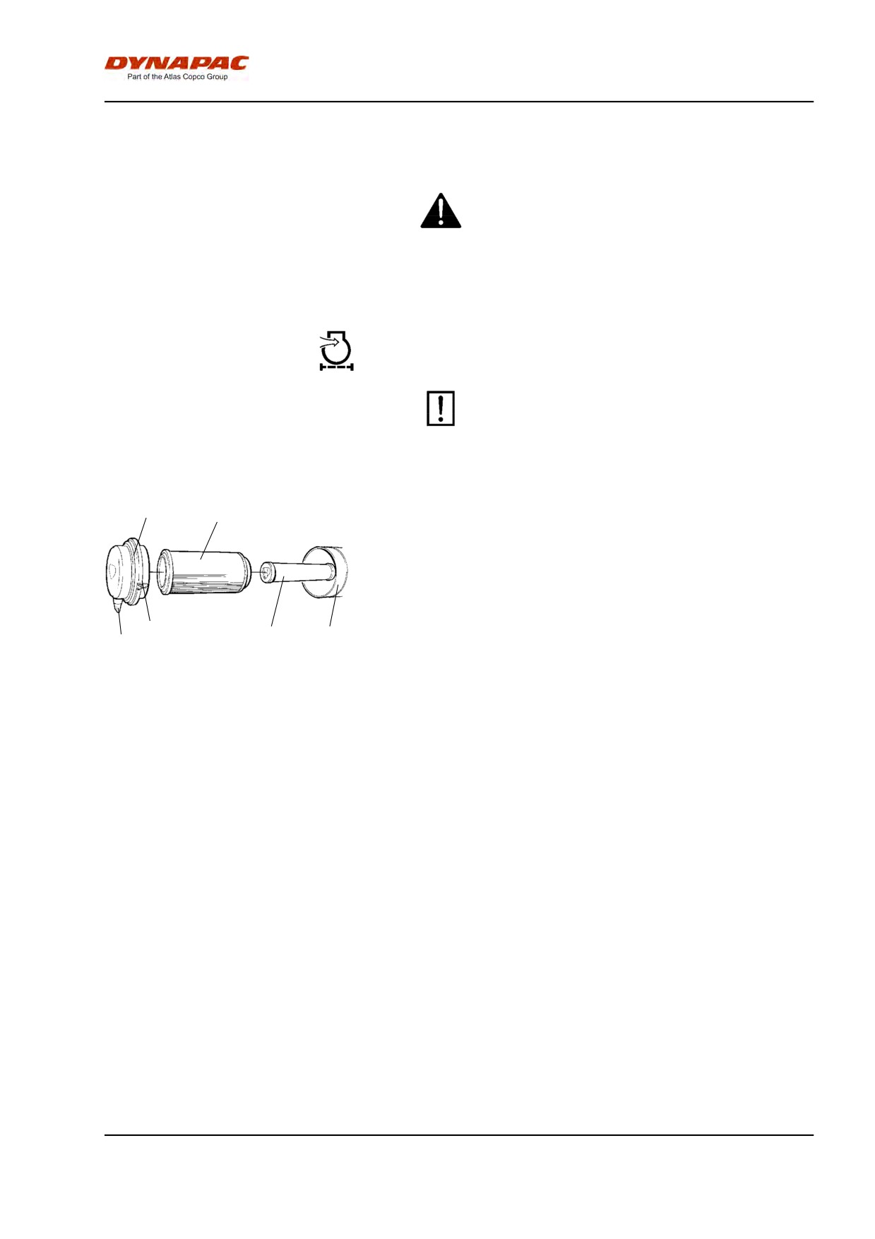
Maintenance - 50h
Maintenance - 50h
Park the roller on a level surface.
When checking and making adjustments, the
engine should be switched off and the
emergency/parking brake should be applied, if
not otherwise specified.
Air cleaner
Checking - Change the main air filter
Change the air cleaner main filter when the
warning lamp on the control panel comes on
when the engine is running at maximum speed.
2
3
Release the clips (1), pull off the cover (2), and pull out
the main filter (3).
Do not remove the backup filter (4).
Clean the air cleaner if necessary, see section Air
cleaner - Cleaning.
When replacing the main filter (3), insert a new filter
1
4
5
6
and refit the air cleaner in the reverse order.
Fig. Air cleaner
Check the condition of the dust valve (6); replace if
1. Clips
necessary.
2. Cover
3. Main filter
4. Backup filter
When refitting the cover, make sure that the dust valve
5. Filter housing
is positioned downwards.
6. Dust valve
83
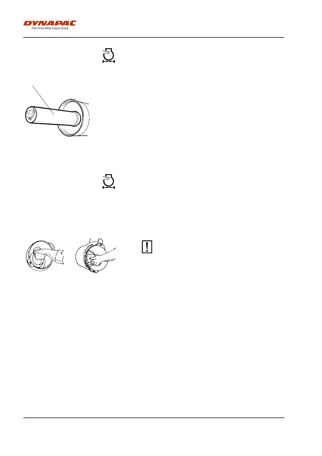
Maintenance - 50h
Backup filter - Change
1
Change the backup filter with a new filter after every
third replacement of the main filter.
To change the backup filter (1), pull the old filter out of
its holder, insert a new filter and reassemble the air
cleaner in the reverse order.
Clean the air cleaner if necessary, see section Air
cleaner - Cleaning.
Fig. Air filter
1. Backup filter
Air cleaner
- Cleaning
Wipe clean the inside of the cover (2) and the filter
housing (5). See the previous illustration.
Wipe clean on both sides of the outlet
pipe.
Wipe also both surfaces for the outlet pipe; see
adjacent figure.
Check that the hose clamps between the filter
housing and the suction hose are tight and that
the hoses are intact. Inspect the entire hose
system, all the way to the engine.
Inner edge of
Outer edge of outlet
outlet pipe.
pipe.
84
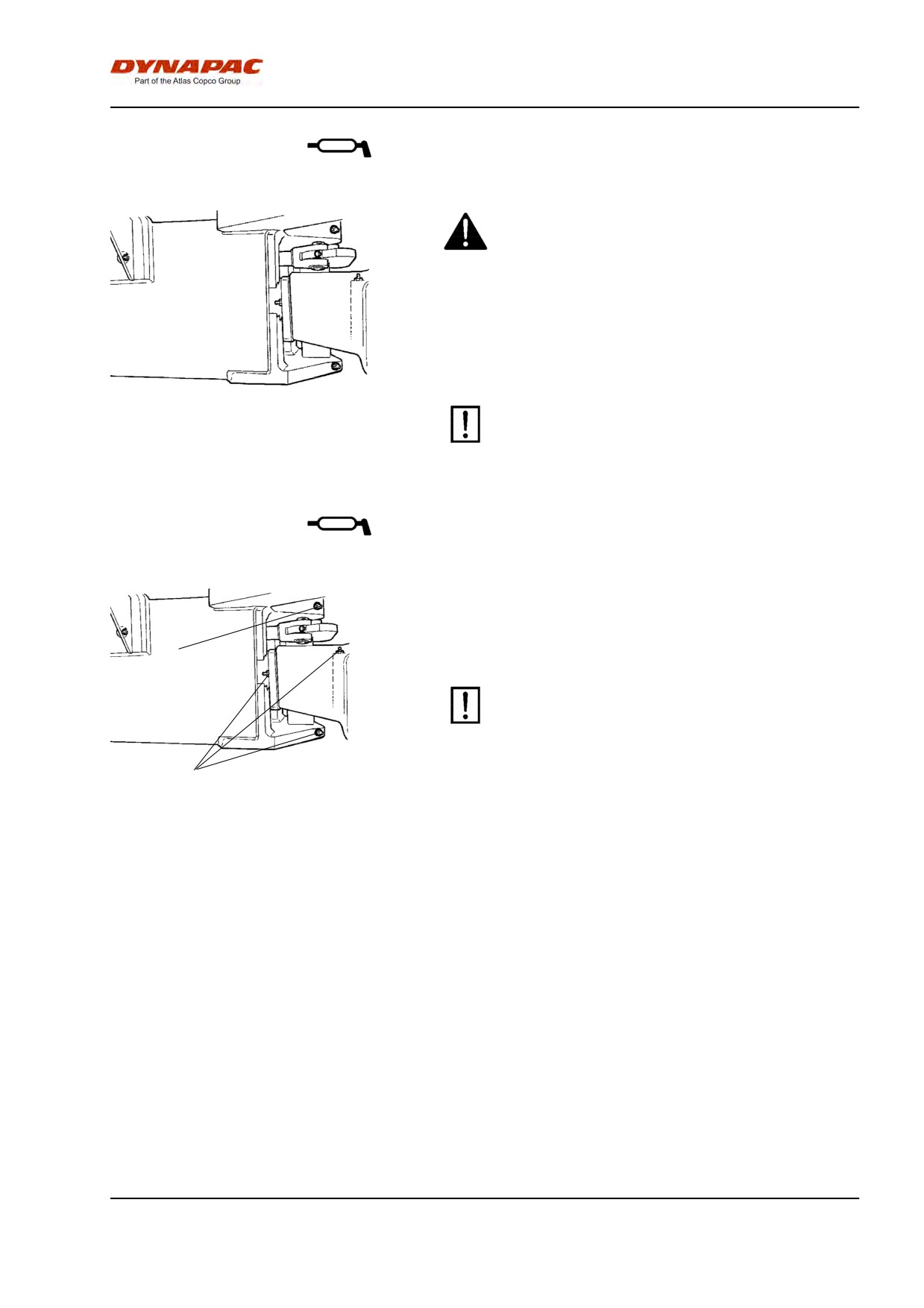
Maintenance - 50h
Articulation - Lubrication
Do not allow anyone to remain in the vicinity of the
steering joint when the engine is running. Risk of
being crushed when the steering is operated.
Press the emergency/parking brake knob before
lubricating.
Turn the steering wheel fully to the left to gain access
to all the steering system's lubricating nipples (4) on
the right-hand side of the machine.
Fig. Steering hitch right side
Use grease as per the lubricant specification
Steering joint - Lubrication
Wipe off any dirt and grease from the nipples.
Grease each nipple (1) with five strokes of a
1
hand-operated grease gun. Make sure that grease
penetrates into the bearings.
If grease does not penetrate the bearings, it may
be necessary to relieve the articulation joint with a
jack while repeating the greasing process.
1
Fig. Articulation, right side
1. Lubricating nipples, articulation
(4 pcs)
85
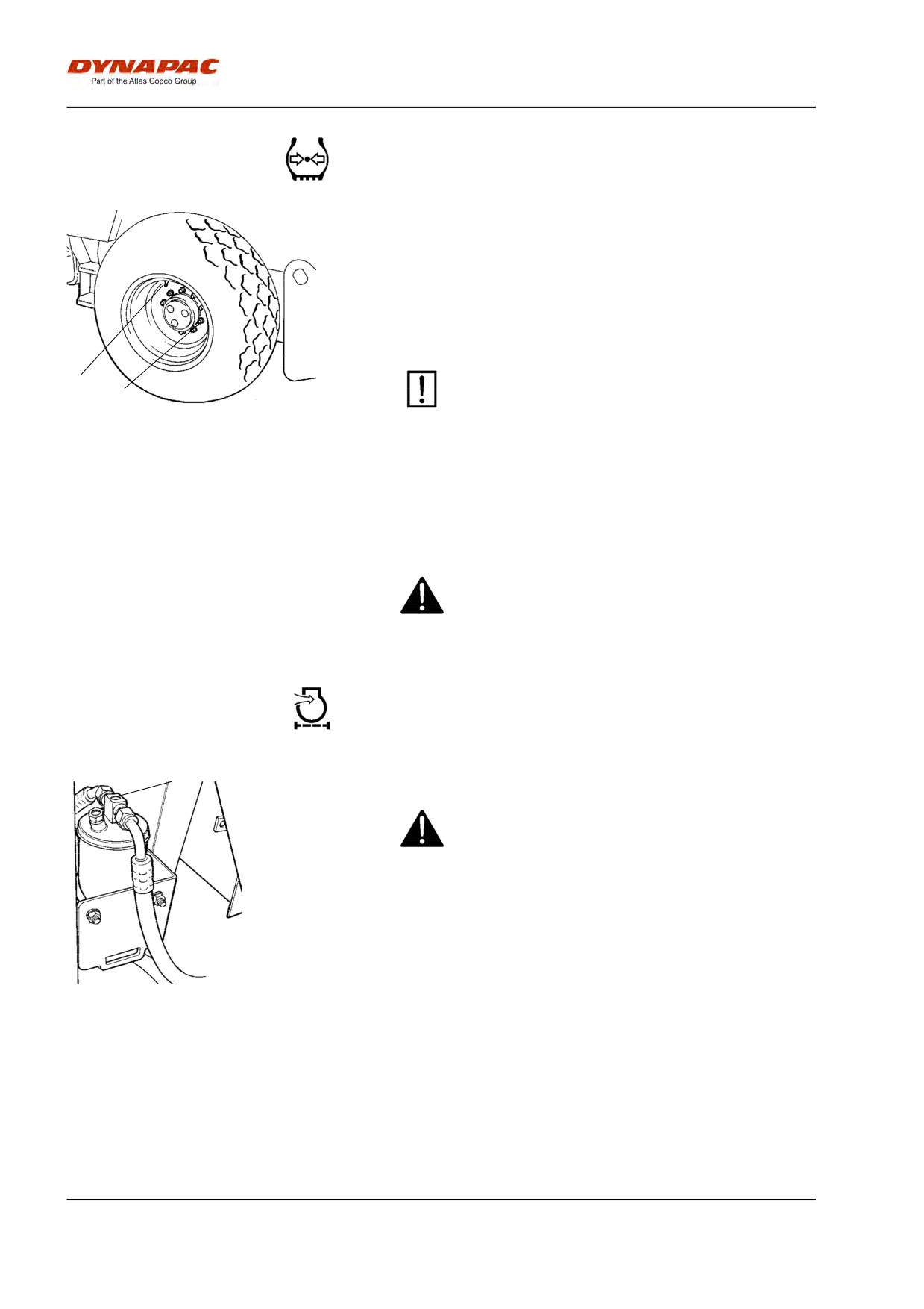
Maintenance - 50h
Tires - Air pressure - Wheel nuts - Tightening
Check the tire pressures using a pressure gauge.
If the tires are filled with fluid, the air valve (1) must be
in the "12 o'clock" position during pumping.
Recommended pressure: See Technical
Specifications.
Check the tire pressure.
1
When changing the tires it is important that both
2
of them have the same rolling radius. This is
necessary to ensure proper functioning of the
Fig. Wheels
anti-slip in the rear axle.
1. Air valve
2. Wheel nut
Check the tightening torque of the wheel nuts (2) at
630 Nm (465 lbf.ft).
Check both wheels and all nuts. (This only applies to a
new machine or newly fitted wheels).
Check the safety manual that accompanies the
roller before filling the tires with air.
Automatic Climate Control (Optional) -
Inspection
1
The system described in this manual is type ACC
(Automatic Climate Control).
Never work under the roller when the engine is
running. Park the roller on a level surface, chock
the wheels and depress the parking brake control.
With the unit in operation, open the engine hood and
check using the sight glass (1) that bubbles are not
visible on the drying filter.
The filter is located on the left side of the engine
Fig. Drying filter
1. Sight glass
compartment's front edge. If bubbles are visible
through the sight glass, it is a sign that the refrigerant
level is too low. If so, stop the unit. The unit may be
damaged if it is run with insufficient refrigerant.
86
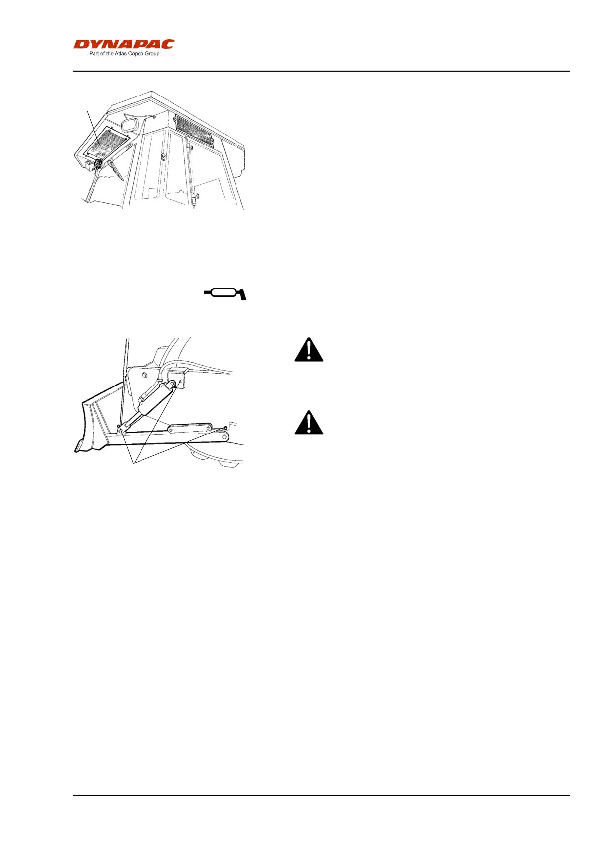
Maintenance - 50h
1
Where cooling capacity is markedly reduced, clean the
condensor element (1) located on the rear edge of the
cab. Also clean the cooling unit in the cab. See under
the heading 2000 hours, automatic climate control -
overhaul.
Fig. Cab
1. Condensor element
Strike-off blade (Optional)
- Lubrication
Always lower the blade to the ground before
leaving or parking the roller.
Make sure that nobody is in the way when
operating the blade.
1
Wipe the nipples clean from grease and dirt, three on
Fig. Strike-off blade
each side of the machine.
1. Lubrication nipples
Grease each nipple (1) with four strokes of the grease
gun. Ensure that grease penetrates the bearings.
87
Maintenance - 50h
88
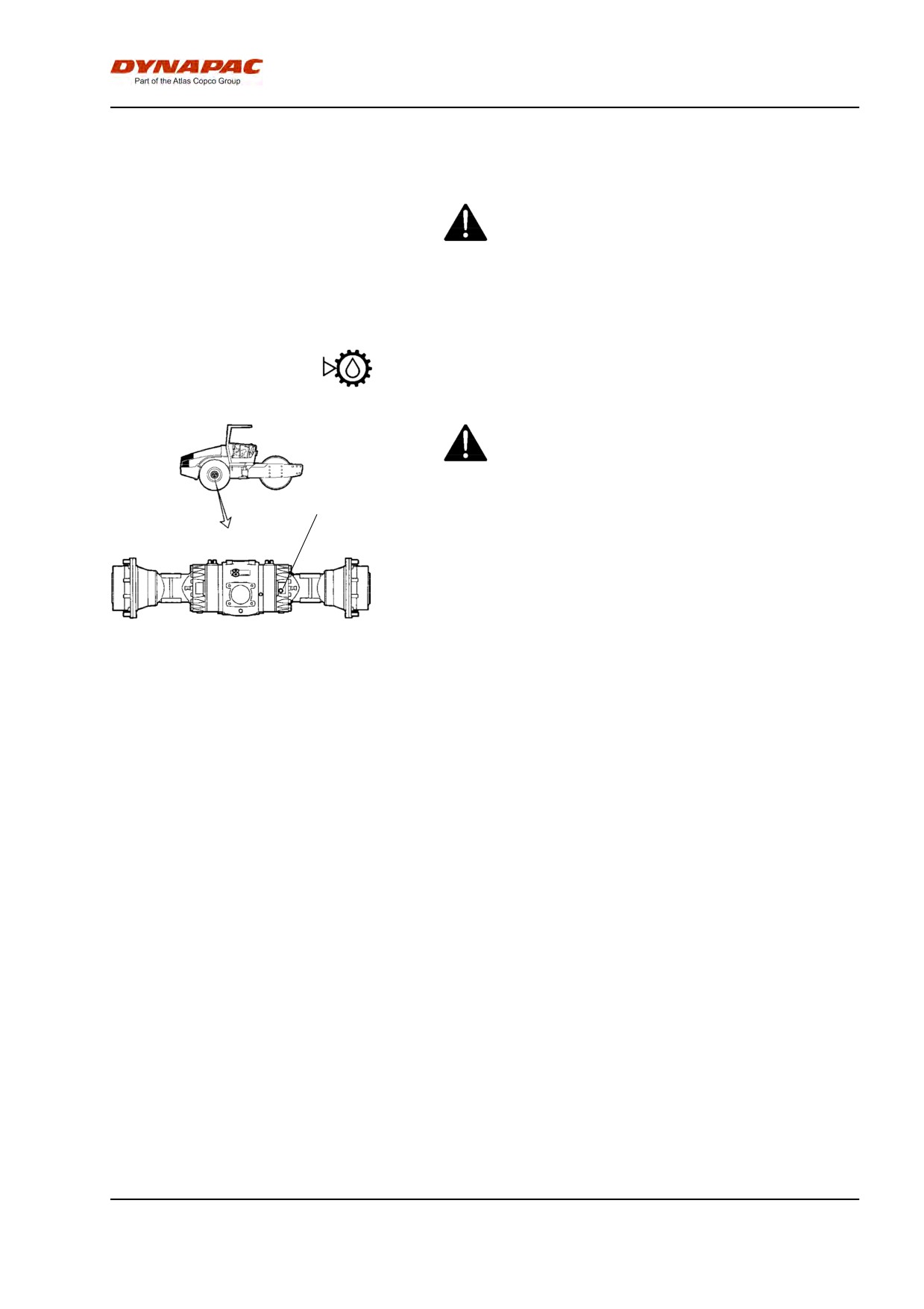
Maintenance - 250h
Maintenance - 250h
Park the roller on a level surface.
When checking and making adjustments, the
engine should be switched off and the
emergency/parking brake should be applied, if
not otherwise specified.
Rear axle differential - Check oil level
Never work under the roller when the engine is
running. Park on a level surface. Block the wheels
securely.
1
Wipe clean and remove the level plug (1) and check
that the oil level reaches the lower edge of the plug
hole. Top off with oil to the right level if the level is low.
Use transmission oil according to the lubricant
specification.
Clean and refit the plug.
Fig. Level check - differential housing
1. Level/Filler plug
89
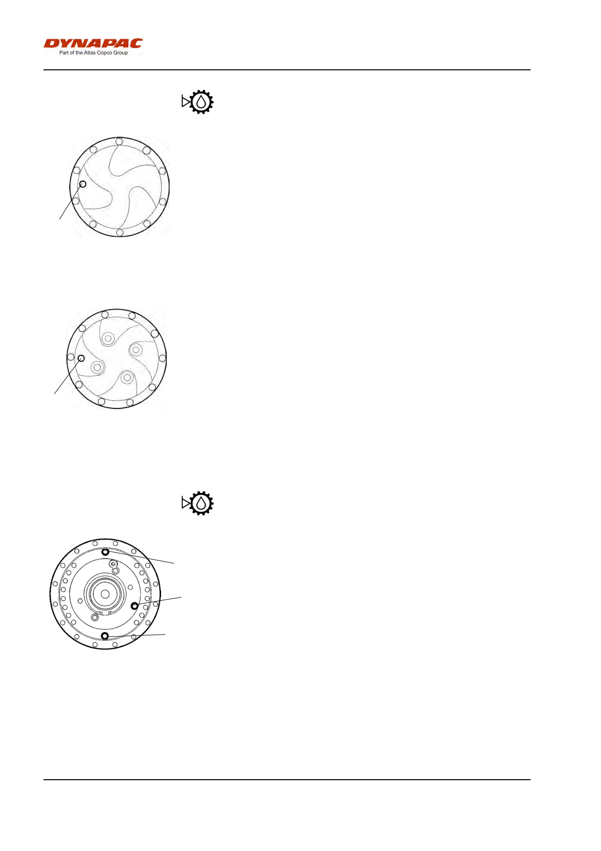
Maintenance - 250h
Rear axle planetary gears - Check oil level
Position the roller with the plug in the planetary gear
(1) in the "9 o'clock" position.
Wipe clean and remove the level plug (1) and check
that the oil level reaches the lower edge of the plug
hole. Top off with oil to the right level if the level is low.
Use transmission oil. See lubrication specification.
1
Clean and refit the plug.
Fig. Level check - planetary gear, std
Check the fluid level in the same way on the rear
1. Level/Filler plug
axle's other planetary gear.
1
Fig. Level check - planetary gear,
optional
1. Level/Filler plug
Drum gearbox - Checking the oil level
Position the drum so that the filler plug (2) is straight
2
up.
Wipe clean the area around the level plug (1) and then
undo the plug.
1
Ensure that the oil level reaches up to the lower edge
of the plug hole.
3
Top off with oil to the right level if the level is low. Use
Fig. Oil level check - drum gearbox
transmission oil according to the lubricant specification.
1. Level plug
2. Filler plug
Clean and refit the plugs.
3. Drain plug
90
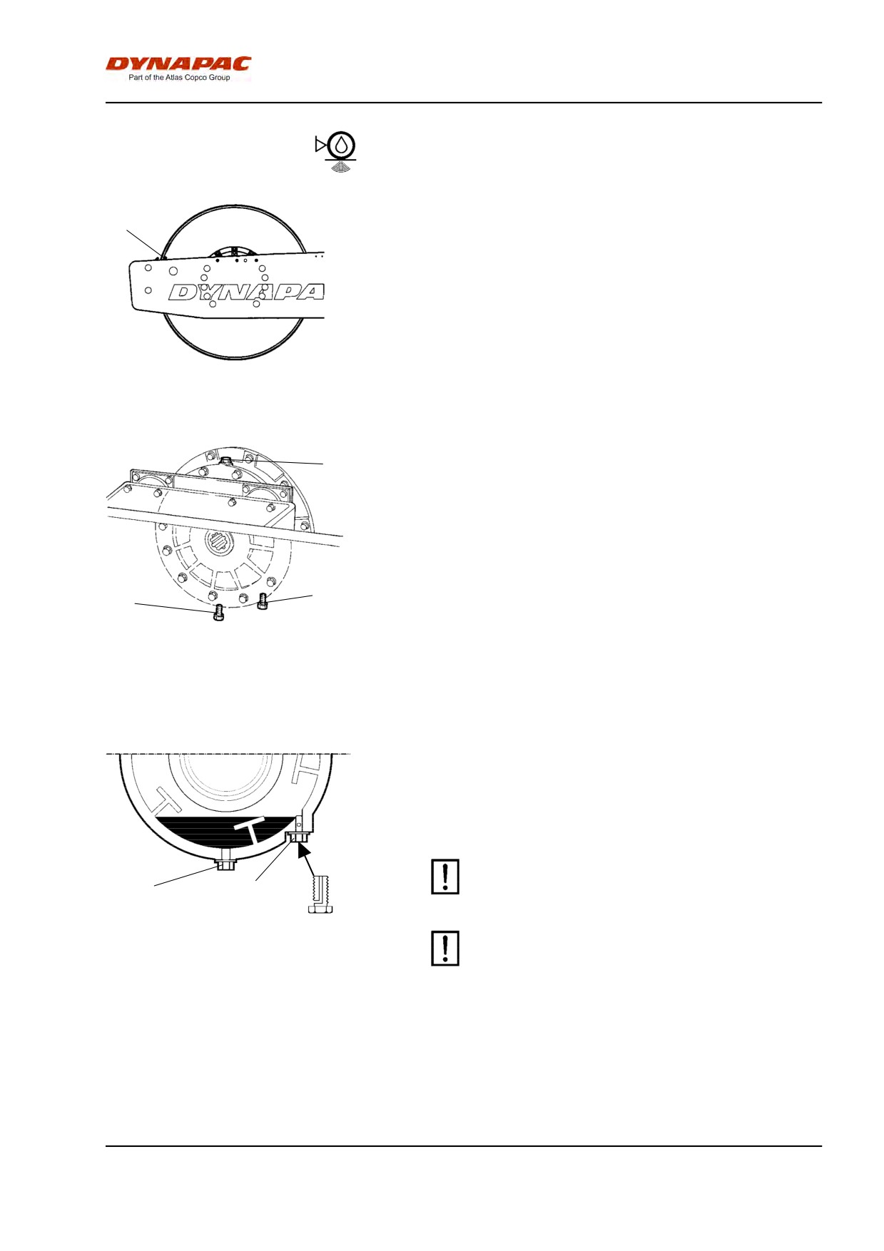
Maintenance - 250h
Drum cartridge - Checking the oil level
Position the machine level so that the indicator pin (1)
1
on the inside of the drum is aligned with the top of the
drum frame.
Fig. Left drum side
1. Indicator pin
1
Wipe clean the filler plug (1) and level plug (3).
Unscrew the filler plug (1).
3
2
Fig. Right drum side
1. Filler plug
2. Drain plug
3. Level plug
Then loosen the level plug (3) on the underside of the
cartridge and unscrew it until the hole in the middle of
the plug becomes visible.
Top off with oil through the filler plug (1), until oil
begins to run out from the level plug's (3) hole. The
level is correct when it stops running.
Ensure that only MOBIL SHC 629 is used in the
cartridges..
2
3
Fig. Drum cartridge
2. Drain plug
Do not overfill with oil - risk for overheating.
3. Level plug
Clean and refit the plugs. Now repeat the procedure
on the opposite side.
91
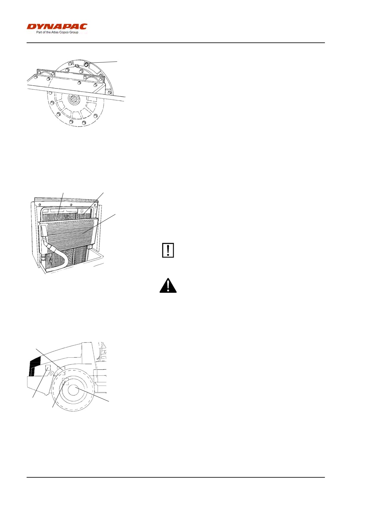
Maintenance - 250h
1
Drum cartridge - Cleaning the ventilation screw
Clean the drum's ventilation hole and ventilation screw
(1). The hole is required to eliminate excess pressure
inside the drum.
Fig. Drum
1. Ventilation screw
Radiator - Check/Cleaning
1
2
Check that air can pass unobstructed through the
radiators (1), (2) and (3).
3
Clean a dirty radiator using compressed air or a
high-pressure water jet.
Blow air or direct water through the cooler in the
opposite direction to that of the cooling air.
Be careful when using a high-pressure washer -
do not place the nozzle too close to the radiator.
Wear protective goggles when working with
Fig. Engine compartment
1. Water cooler
compressed air or high-pressure water jets.
2. Charge air cooler
3. Hydraulic fluid cooler
Bolted joints - Checking tightening torque
1
Steering pump against engine (1) 38 Nm (28 lbf.ft).
Rear axle suspension (2) 330 Nm (243 lbf.ft), oiled.
Engine mounting (3). Check that all M12 bolts (x20)
are tightened, 78 Nm (57 lbf.ft).
Wheel nuts (4). Check that all nuts are tightened, 630
Nm oiled.
3
4
2
(The above applies to new or replaced components
only).
Fig. Right side of machine
1. Steering pump
2. Rear axle
3. Engine suspension
4. Wheel nuts
92
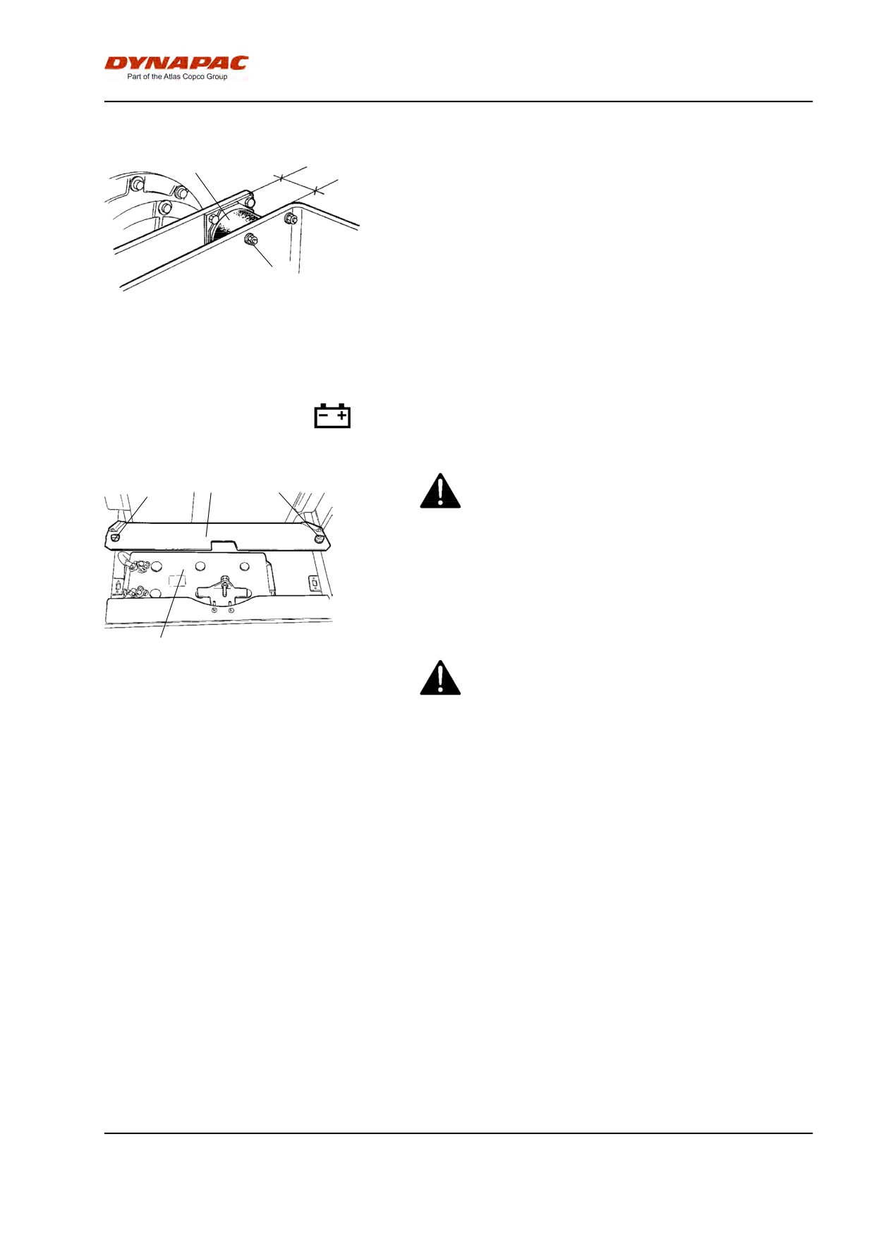
Maintenance - 250h
Rubber elements and fastening screws - Check
1
Check all rubber elements (1), replace all of the
elements if more than 25% of them on one side of the
drum are cracked deeper than 10-15 mm (0.4-0.6 in).
Check using a knife blade or pointed object.
Check also that the screw fasteners (2) are tightened.
2
Fig. Drum, vibration side
1. Rubber element
2. Fastening screws
Battery - Check electrolyte level
1
2
1
Never use a naked flame when checking the
battery as the electrolyte emits explosive gas while
the alternator is charging.
Lift up the engine compartment cover and undo the
quick-release screws (1).
Raise the battery cover (2).
Wipe the top of the battery.
3
Fig. Battery shelf
Wear safety goggles. The battery contains
1. Quick-screws
corrosive acid. Rinse with water if electrolyte
2. Battery cover
comes into contact with the body.
3. Battery
93
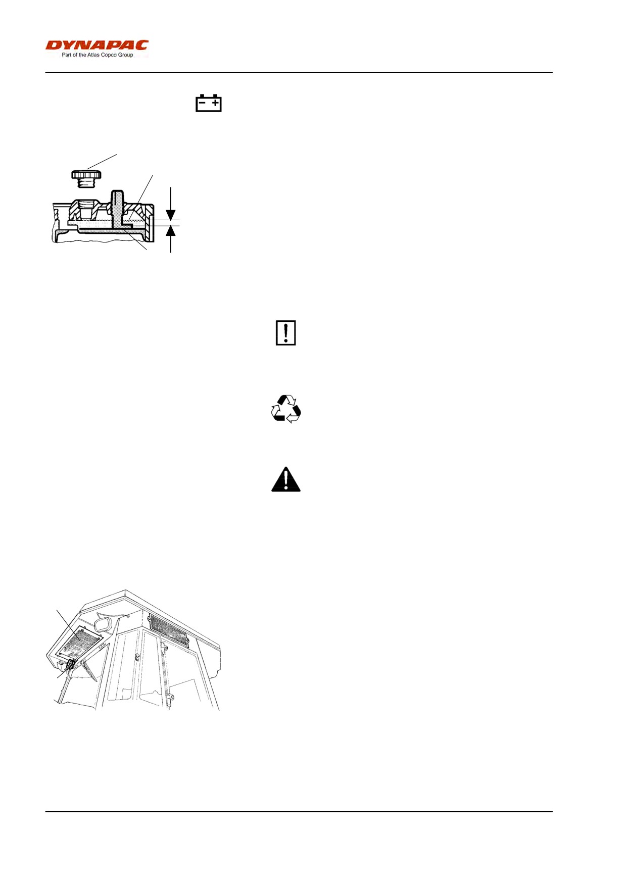
Maintenance - 250h
Battery cell
1
Take off the cell caps (1) and make sure that
2
electrolyte (2) is about 10 mm (0.4 in) above the plates
(3). Check the level of all cells. Top off with distilled
water to the right level if the level is low.
10 mm
If the ambient temperature is below freezing, run the
engine for a while before topping off with distilled
(0.4 in)
water. Otherwise the electrolyte might freeze.
3
Make sure that ventilation holes in the cell cover are
not clogged, then put the cover back on.
The cable shoes should be clean and well tightened.
Fig. Electrolyte level in battery
1. Cell cap
Clean corroded cable shoes and grease them with
2. Electrolyte level
acid-free Vaseline.
3. Plate
Always disconnect the negative cable first when
disconnecting the battery. When connecting the
battery, always connect the positive cable first.
Discard used batteries wisely. Batteries contain
lead, which is harmful to the environment.
Before doing any electric welding on the machine,
disconnect the battery ground cable and then all
electrical connections to the alternator.
Air conditioning (Optional)
- Inspection
Inspect refrigerant hoses and connections and make
2
sure that there are no signs of an oil film that can
indicate a refrigerant leakage.
1
Fig. Air conditioning
1. Refrigerant hoses
2. Condensor element
94
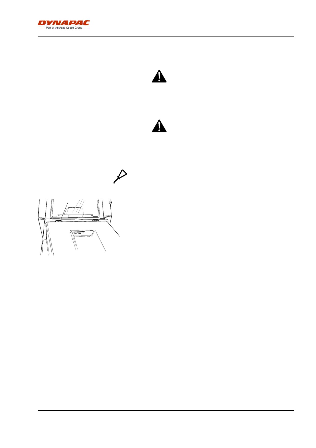
Maintenance - 500h
Maintenance - 500h
Park the roller on a level surface.
When checking and making adjustments, the
engine should be switched off and the
emergency/parking brake should be applied, if
not otherwise specified.
Ensue that there is good ventilation (air
extraction) if the engine is run indoors. Risk of
carbon monoxide poisoning.
Controls and moving joints - Lubrication
1
Lubricate engine hood hinges (1) and the slide rails of
the operator's seat with grease, other joints and
controls with oil. Lubricate the cab hinges with grease.
See the lubrication specification.
Fig. Engine hood
1. Hinge
95
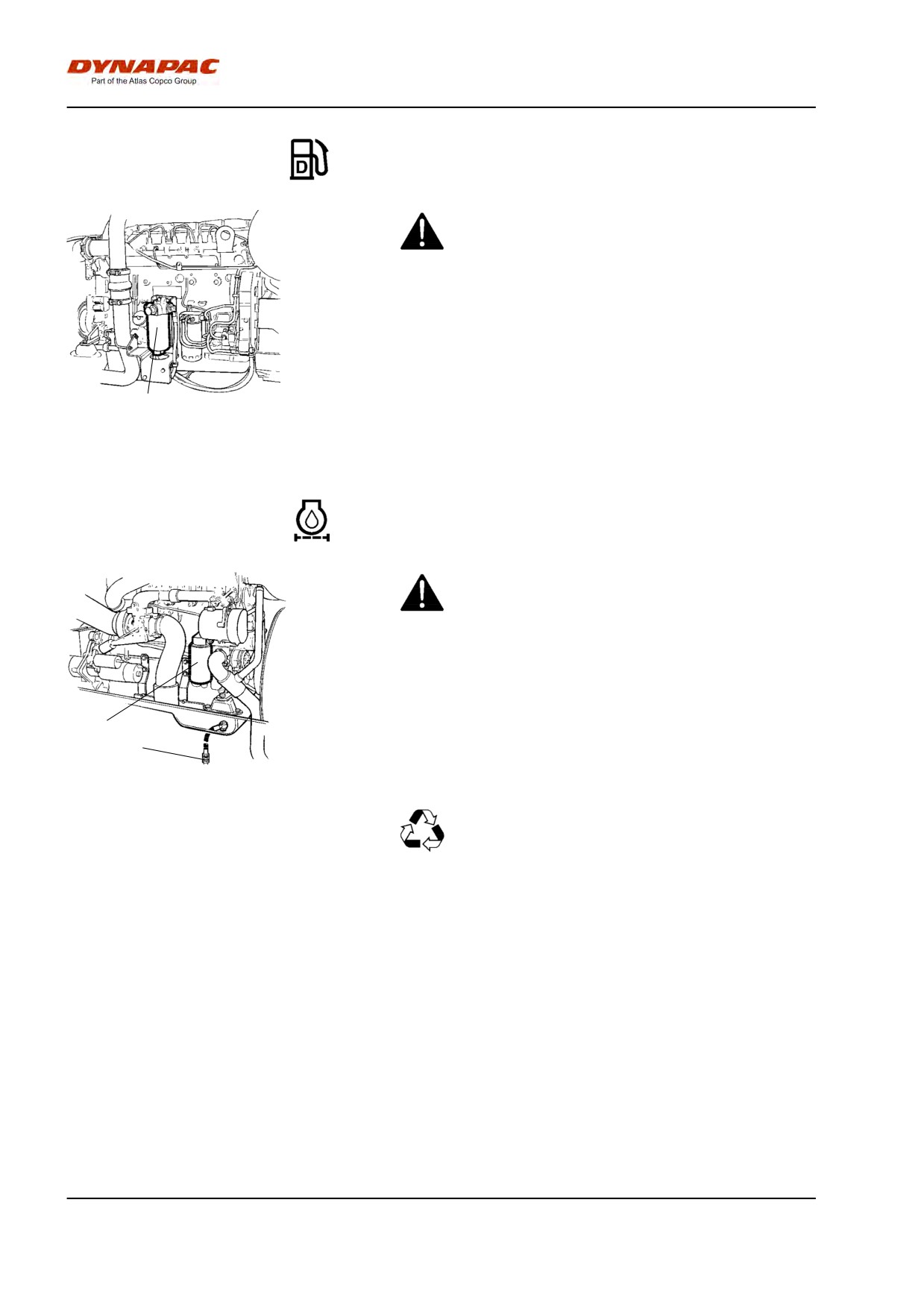
Maintenance - 500h
Fuel pre-filter - Cleaning
Ensure good ventilation (air extraction) if the
diesel engine is run indoors. Risk of carbon
monoxide poisoning.
See instruction manual for the engine when cleaning
the filter, the chapter on the fuel system.
1
Fig. Engine compartment
1. Fuel prefilter
Diesel engine - Oil and Filter change
Take great care when draining warm fluid and oil.
Wear protective gloves and goggles.
The oil drain plug (1) is most easily accessible from
the bottom of the engine and is located attached to a
hose on the rear axle.. Drain the oil when the engine is
2
warm. Place a receptacle that holds at least 19 liters
1
(5 gal) under the drain plug.
Fig. Left side of engine
Replace the engine oil filter (2) at the same time. Refer
1. Drain plug
to the engine manual.
2. Oil filter
Deliver the drained oil and filter to
environmentally correct handling.
96
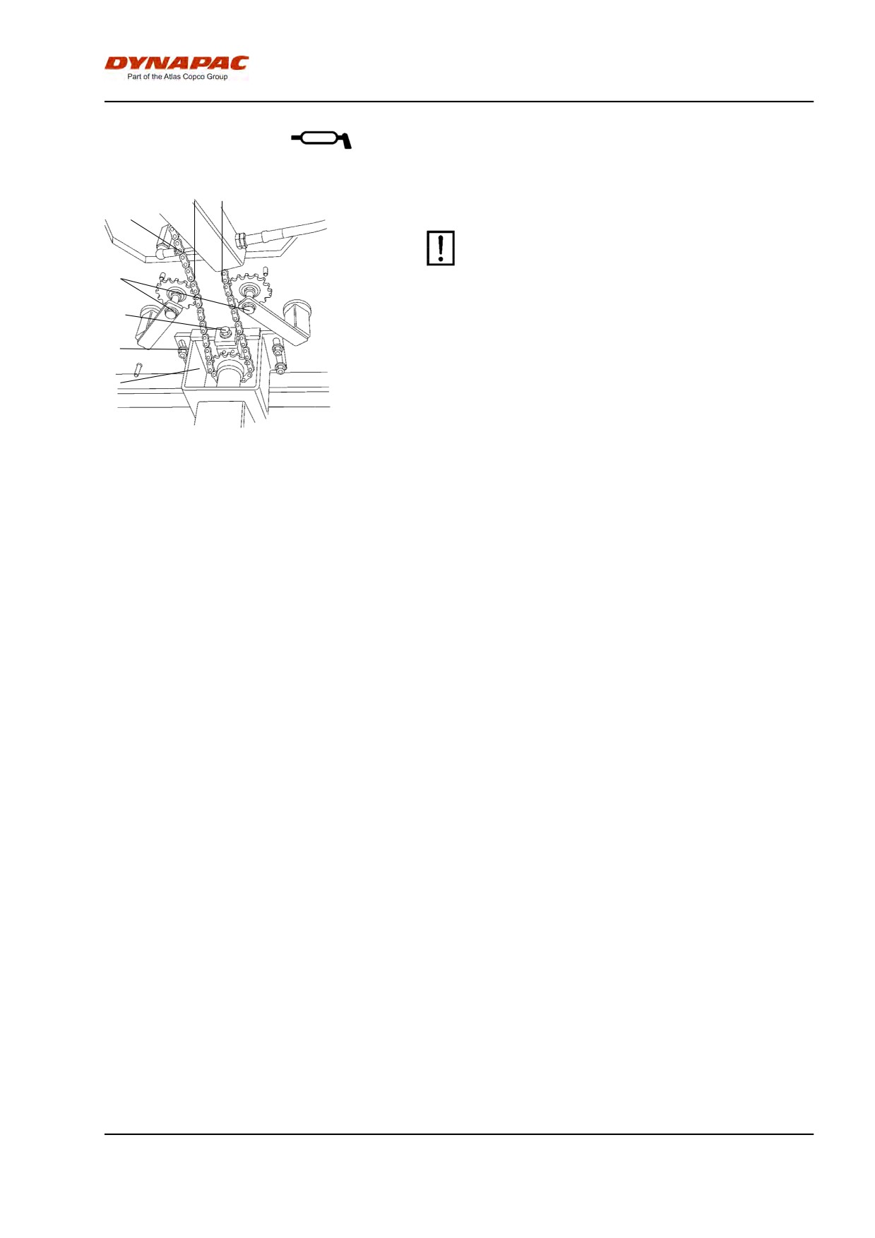
Maintenance - 500h
Steering chain and seat bearing - Lubrication
1
a
Optional on rollers without cab
Keep in mind that the chain is a vital part of the
steering mechanism.
2
3
Clean and lubricate the chain (1) between the seat
bearing and steering valve with grease. The chain can
4
be accessed from underneath the operator's position.
5
It is not necessary to remove the chain.
Adjust the chain as follows if it has slackened so that
size "a" is less than 30 mm (1.2 in): Loosen the nuts
Fig. Underneath operator's position
(4) and adjust the mount (5) backwards with the
1. Steering chain
adjusting nut (3) until size "a" is 50 mm (2 in).
2. Chain-tightening device
3. Adjusting nut
4. Nuts
5. Control valve mount
97
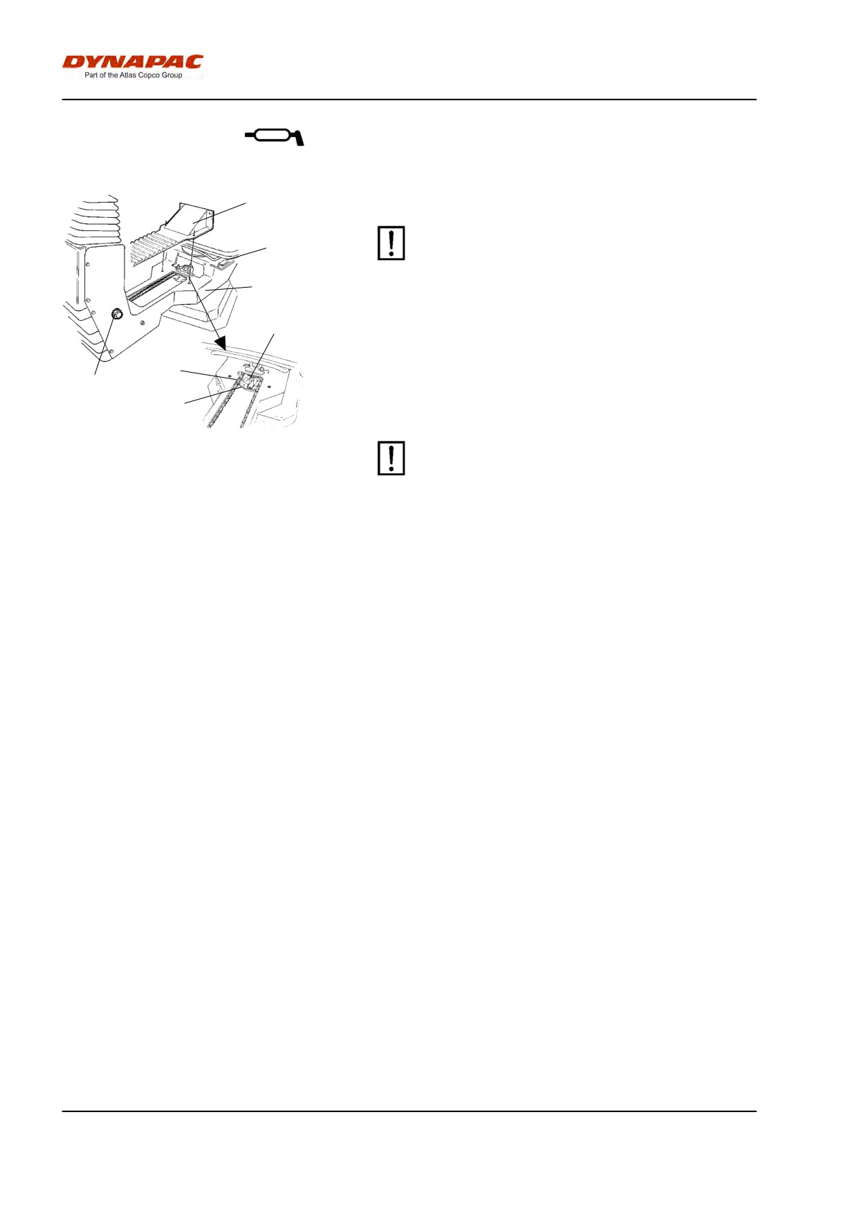
Maintenance - 500h
Seat bearing - Lubrication
5
Optional on rollers without cab
Keep in mind that the chain is a vital part of the
6
steering mechanism.
7
2
Remove the cover (5) to access the lubrication nipple
(1). Lubricate the operator seat slew bearing with three
strokes of a hand-operated grease gun.
3
4
Lubricate the seat locking latch (7) (accessible from
below).
1
Also grease the seat slide rails (6).
Fig. Seat bearing
If the seat starts to be stiff when adjusting, it
1. Grease nipple
should be lubricated more often than specified
2. Cogwheel
here.
3. Steering chain
4. Adjusting screw
5. Cover
6. Slide rails
7. Slew interlock
Clean and grease the chain (3) between the seat and
the steering column.
If the chain is slack on the sprocket (2), loosen the
screws (4) and move the steering column forward.
Tighten the screws and check chain tension.
98
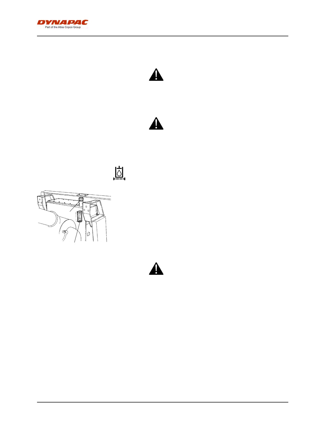
Maintenance - 1000h
Maintenance - 1000h
Park the roller on a level surface.
When checking and making adjustments, the
engine should be switched off and the
emergency/parking brake should be applied, if
not otherwise specified.
Ensue that there is good ventilation (air
extraction) if the engine is run indoors. Risk of
carbon monoxide poisoning.
Hydraulic filter - Replacement
Undo the filler cap/bleeder filter (2) on top of the
reservoir so that over-pressure inside the reservoir can
be eliminated.
2
Make sure that the bleeding filter (2) is not clogged, air
must have unobstructed passage through the cap in
both directions.
If passage in either direction is blocked, clean the filter
3
with a little diesel oil and blow through with
compressed air until the block is removed, or replace
the cap with a new one.
Wear protective goggles when working with
Fig. Hydraulic reservoir
compressed air.
2. Filler cap/Bleeding filter
3. Sight glass
99
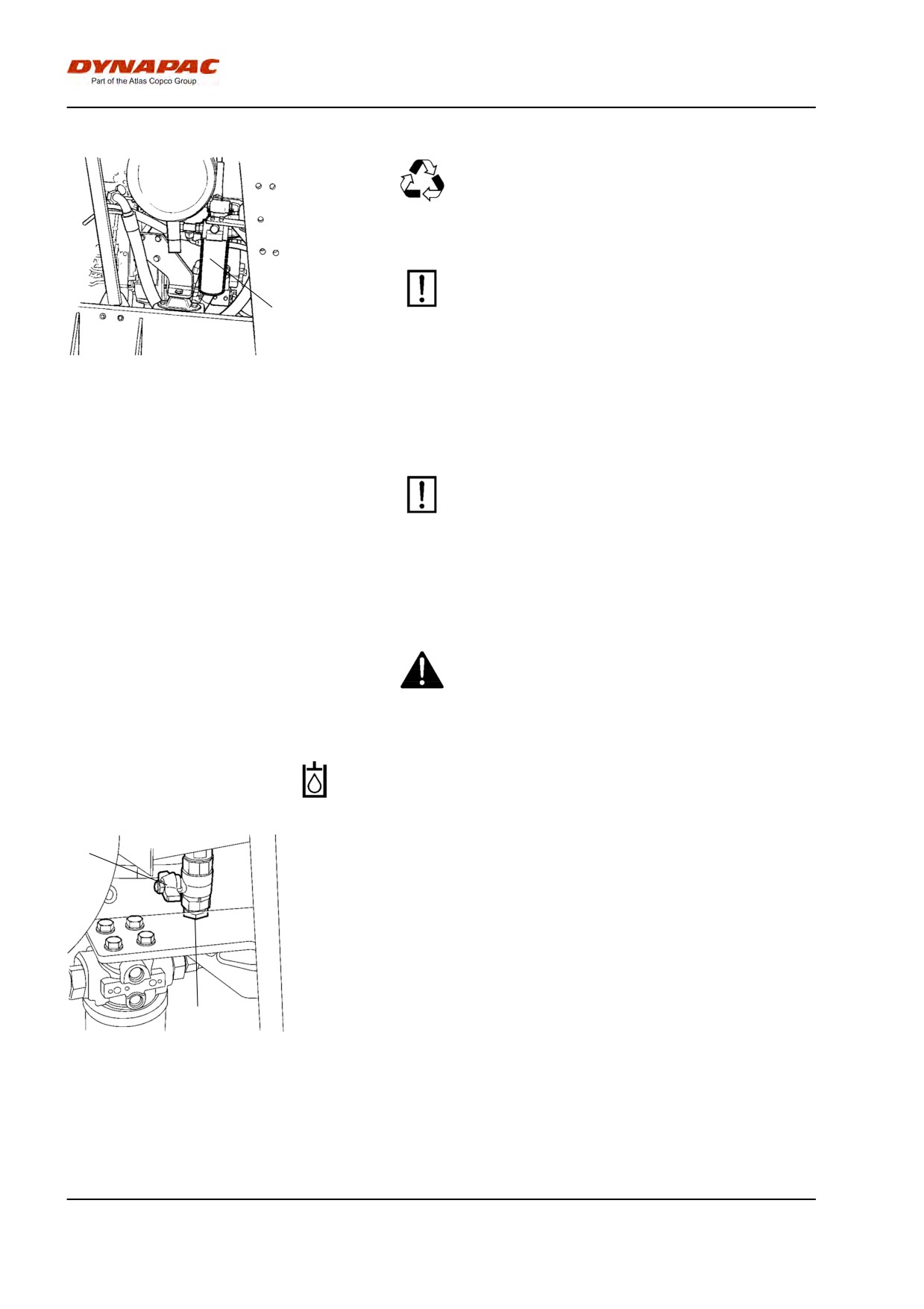
Maintenance - 1000h
Clean thoroughly around the oil filters.
Remove the oil filters (1) and dispose of them in
an approved manner. They are single-use filters
and cannot be cleaned.
Make sure that the old sealing rings are not left
on the filter holders, as this could cause leakage
1
between the new and old gaskets.
Fig. Engine compartment
Thoroughly clean the sealing surfaces of the filter
2. Hydraulic fluid filter (x2).
holders.
Apply a thin coat of fresh hydraulic fluid to the rubber
gaskets on the new filters. Screw on the filter by hand.
First tighten the filter until its seal is in contact
with the filter attachment. Then turn an additional
half revolution. Do not tighten the filter too hard
as this could damage the gasket.
Start the engine and ensure that there is no leakage of
hydraulic fluid from the filters. Check level of fluid in
the sight glass (3) and top up as required.
Ensue that there is good ventilation (air extraction)
if the engine is run indoors. Risk of carbon
monoxide poisoning.
Hydraulic reservoir - Draining
1
The condensate from the hydraulic reservoir is drained
through the drainage tap (1).
Drain the roller after it has been stationary for a long
time, e.g. after standing overnight. Drain as follows:
Remove the plug (2).
Place a container under the tap.
Open the tap (1) and let any trapped condensate run
2
out.
Shut the drainage tap.
Fig. Underside of hydraulic reservoir
1. Drainage tap
Refit the plug.
2. Plug
100
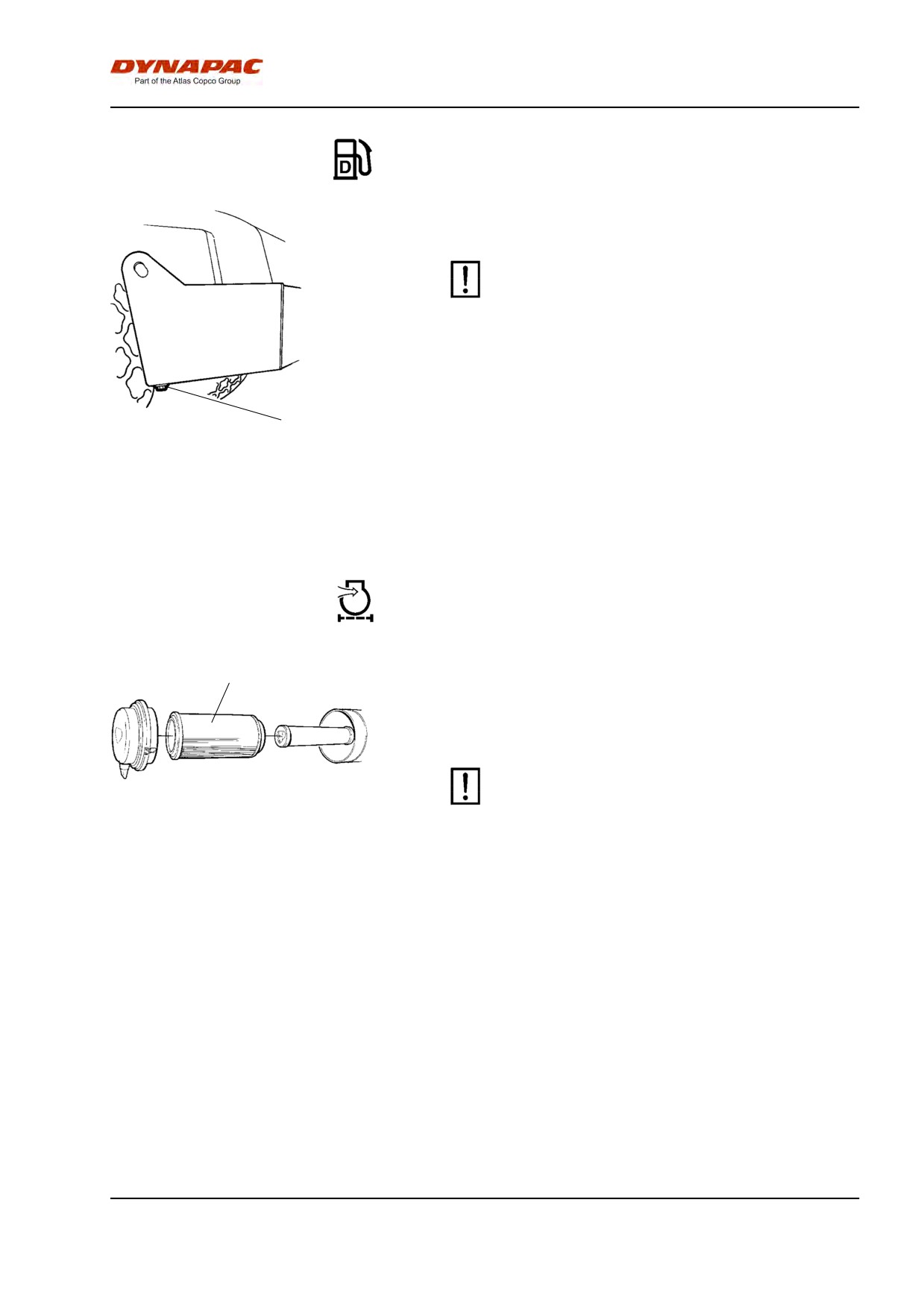
Maintenance - 1000h
Fuel tank - Drainage
Water and sediment in the fuel tank are removed via
the drainage plug in the bottom of the fuel tank.
Be very careful during draining. Do not drop the
plug or else all the fuel will flow out.
Drain the roller after it has been stationary for a long
time, e.g. after standing overnight. The fuel level
1
should be as low as possible.
Fig. Fuel tank
The roller should preferably have been standing with
1. Drain plug
this side somewhat lower, so that water and sediment
will gather near the drainage plug (1). Drain as follows:
Place a container under the plug (1).
Remove the plug and drain the water and sediment
until only pure fuel runs from the plug. Refit the plug.
Air filter - Changing
1
Replace the air cleaner main filter (1) even if it has not
been cleaned five times See under the heading 'Every
50 hours of operation' for information on changing the
filter.
If a blocked filter is not replaced, the exhaust
Fig. Air cleaner
fumes will be black and the engine will loose
1. Main filter
power. There is also a risk of severe damage to
the engine.
101
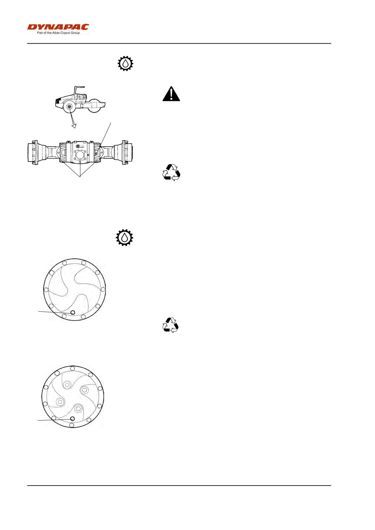
Maintenance - 1000h
Rear axle differential - Oil change
Never work under the roller when the engine is
running. Park on a level surface. Block the wheels
securely.
1
Wipe clean and remove the level/filler plug (1) and all
three drain plugs (2), and then drain the oil into a
suitable receptacle. The volume is approx. 12 liters
(12.7 qts).
Save the oil and dispose of it in an
approved manner.
2
Fig. Rear axle
1. Level/Filler plug
2. Drain plugs
Refit the drainage plugs and top up with fresh oil until
the correct level is reached. Refit the level/filler plug.
Use transmission oil, see Lubricant Specification.
Rear axle's planetary gears - Draining the oil
Position the roller with the plug (1) at its lowest
position.
Wipe clean and remove the plug (1) and drain the oil
into a receptacle. The volume is approx. 2 liters (2.1
qts).
1
Save the oil and hand in to an
environment-friendly waste disposal station.
Fig. Draining the oil - planetary gear,
std
1. Level/Filler plug
1
Fig. Draining the oil - planetary gear,
optional
1. Level/Filler plug
102
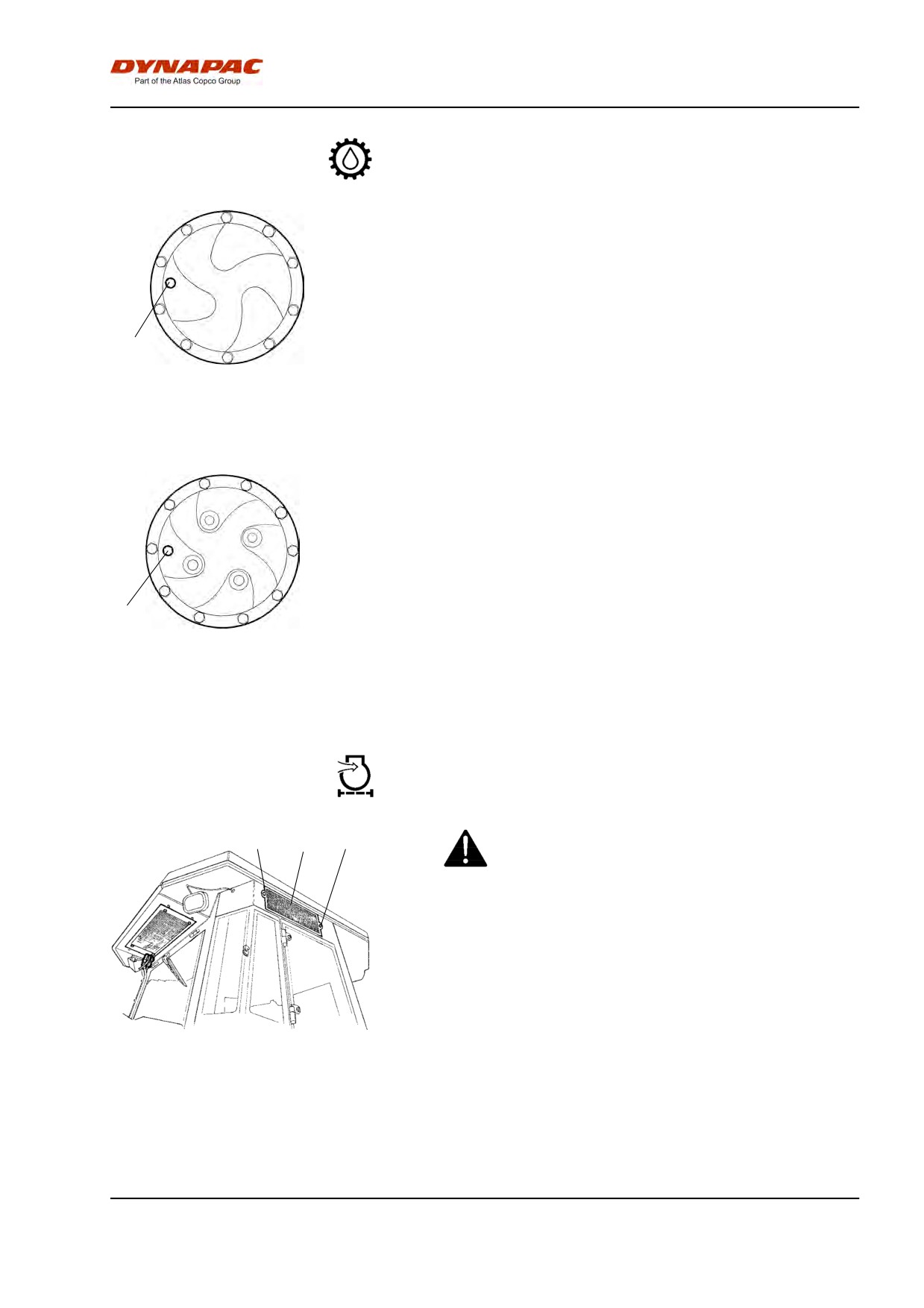
Maintenance - 1000h
Rear axle's planetary gears - Oil change - Oil
filling
Set the roller so that the plug (1) in the planetary gear
is at "9 o' clock".
Wipe clean and remove the plug (1).
Fill with oil to the lower edge of the level hole. Use
transmission oil. See lubrication specification.
1
Clean and refit the plug (1).
Fig. Oil filling - planetary gear, std
Fill with oil in the same way as for the rear axle's
1. Level/Filler plug
second planetary gear.
1
Fig. Oil filling - planetart gear, optional
1. Level/Filler plug
Air conditioning (Optional)
Fresh air filter - Change
2
1
2
Use a step ladder to reach the filter (1). The filter
can also be accessed via the right cab window.
Loosen the two screws (2) on the cab's right side.
Take down the whole holder and remove the filter
insert.
Replace with a new filter.
It may be necessary to change the filter more often if
Fig. Cab
the machine is working in a dusty environment.
1. Fresh air filter
2. Screw (x2)
103
Maintenance - 1000h
104
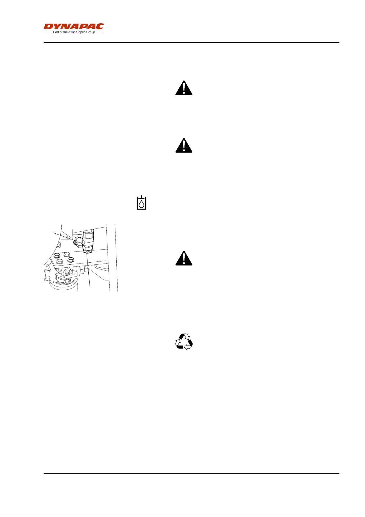
Maintenance - 2000h
Maintenance - 2000h
Park the roller on a level surface.
When checking and making adjustments, the
engine should be switched off and the
emergency/parking brake should be applied, if
not otherwise specified.
Ensue that there is good ventilation (air
extraction) if the engine is run indoors. Risk of
carbon monoxide poisoning.
Hydraulic reservoir - Oil change
1
Obtain a container for collecting the used fluid. The
container should be able to hold at least 60 liters (16
gal).
Observe care when draining hot hydraulic fluid.
Wear protective gloves and goggles.
2
A suitable container may be an empty oil drum or
similar item which is placed beside the roller. The fluid
Fig. Underside of hydraulic reservoir
then runs in a hose from the drainage plug (1) to the
1. Drainage tap
oil drum, after the plug (2) has been removed and the
2. Plug
tap opened.
Save the oil and dispose of it in an approved
manner.
Fill up with fresh hydraulic fluid as per the instructions
under the heading "Hydraulic reservoir - Check fluid
level". Replace the hydraulic fluid filters at the same
time.
Start the diesel engine and operate the various
hydraulic functions.
Check the fluid level and top up if necessary.
105
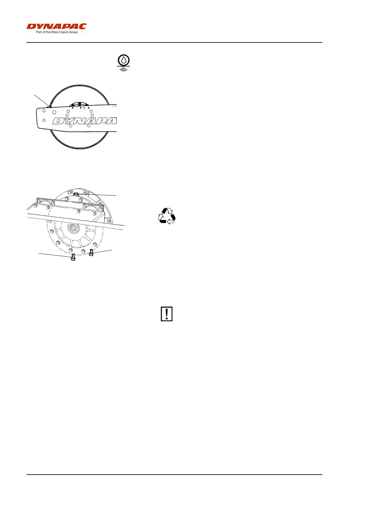
Maintenance - 2000h
Drum cartridge - Oil change
Position the machine level so that the indicator pin (1)
1
on the inside of the drum is aligned with the top of the
drum frame.
Fig. Left drum side
1. Indicator pin
1
Place a receptacle for about 5 liters (1.32 gal)
underneath the drain plug (2).
Save the oil and hand in to an
environment-friendly waste disposal station.
3
Clean and unscrew the filler plug (1) and the drain
2
plug (2).
Allow all the oil to run out. Fit the drain plug and fill
with new synthetic oil in accordance with the
Fig. Right drum side
instructions under "Drum cartridge - checking the oil
1. Filler plug
level".
2. Drain plug
3. Level plug
Repeat the procedure on the opposite side.
Ensure that only MOBIL SHC 629 is used in the
cartridges..
106
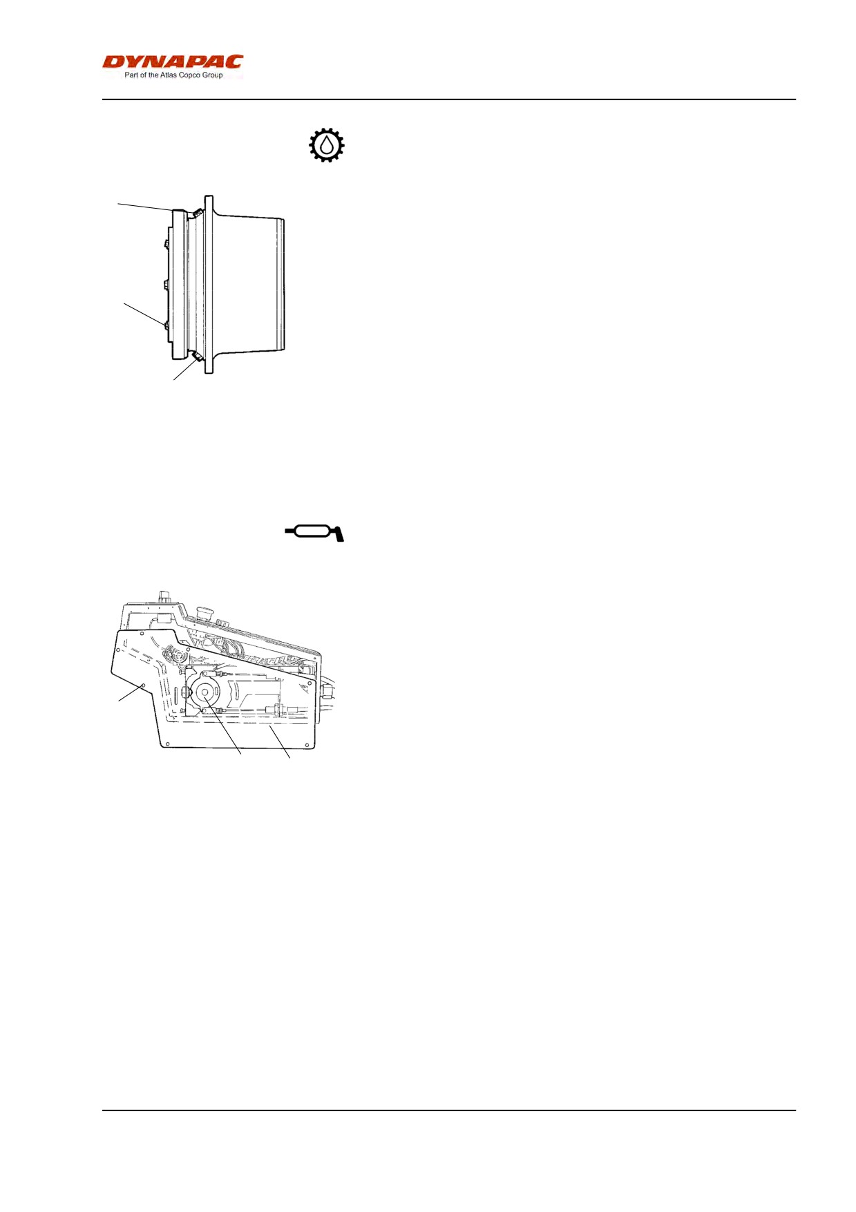
Maintenance - 2000h
Drum gearbox - Oil change
2
Place the roller on a level surface with the plugs (1)
and (2) as illustrated.
Wipe clean, unscrew the plugs (1, 2 and 3) and drain
the oil into a suitable receptacle, capacity about 3.5
liters (1 gal.).
3
Refit the plug (1) and fill with oil up to the level plug
(3), according to "Drum gearbox - Checking the oil
level".
Use transmission oil according to the lubricant
1
specification.
Fig. Drum gearbox
Clean and refit the level plug (3) and filler plug (2).
1. Drain plug
2. Filler plug
3. Level plug
Forward/Reverse lever
- Lubrication
Remove the screws (1) and take off the plate (2).
Grease the contact surface on the cam disc (3).
Refit the plate (2) with the screws (1).
1
3
2
Fig. Forward/Reverse lever
1. Screw
2. Plate
3. Cam disc
107
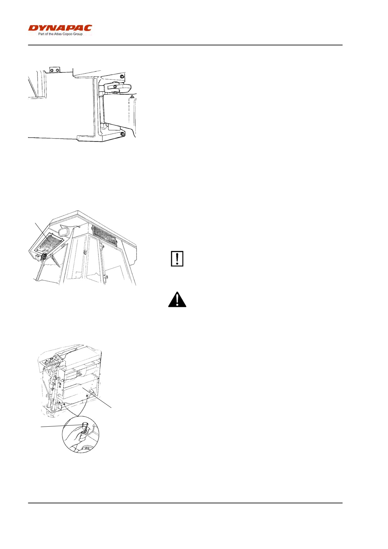
Maintenance - 2000h
Steering hitch - Check
Inspect the steering hitch to detect any damage or
cracks.
Check and tighten any loose bolts.
Check also for any stiffness and play.
Fig. Steering hitch
Automatic Climate Control (Optional)
- Overhaul
Regular inspection and maintenance are necessary to
1
ensure satisfactory long-term operation.
Clean all dust from the condenser element (1) using
compressed air. Blow from above downwards.
The air jet can damage the element flanges if it is
too powerful.
Fig. Cab
Wear protective goggles when working with
1. Condensor element
compressed air.
Inspect the condenser element attachment.
Clean all dust from the cooling unit and the cooling
element (1) using compressed air.
Check the system hoses for chafing. Make sure that
drainage from the cooling unit is unobstructed so that
no condensation accumulates inside the unit.
Drain by pinching the valves (2)
1
2
Fig. Automatic climate control
1. Cooling element
2. Drain valve (x2).
108
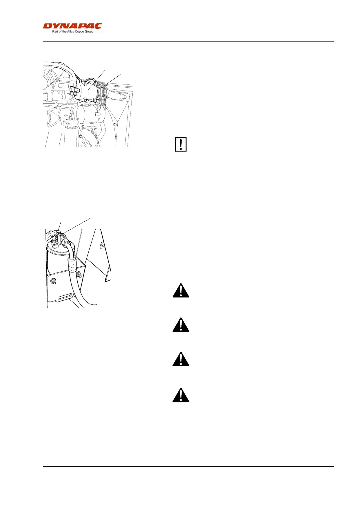
Maintenance - 2000h
Compressor - Check (Optional)
1
Inspect the attachment of the compressor (1).
2
The compressor is located over the alternator in the
engine compartment.
The unit should, if possible, be run at least five
minutes every week to ensure the lubrication of the
gaskets and compressor in the system.
Check the drive belt (2) for any physical damage or
cracks.
The air conditioning unit should not be run when
the outdoor temperature is below 0 C, other than
for the above.
Fig. Engine compartment
1. Compressor
2. Drive belt
Drying filter - Check
2
1
With the unit in operation, open the engine hood and
check using the sight glass (1) that bubbles are not
visible on the drying filter. If bubbles are visible
through the sight glass, it is a sign that the refrigerant
level is too low. If so, stop the unit. The unit may be
damaged if it is run with insufficient refrigerant.
Check the moisture indicator (2). It should be blue. If it
is beige, the dryer cartridge should be changed by an
authorized service company.
The compressor will be damaged if the unit is run
with too little refrigerant.
Do not disconnect or undo the hose couplings.
Fig. Drying filter in engine
compartment
1. Sight glass
2. Moisture indicator
The cooling system is pressurized. Incorrect
handling can result in serious personal injury.
The system contains pressurized refrigerant. It is
forbidden to release refrigerants into the
atmosphere. Work on the refrigerant circuit is only
to be carriedd out by authorized companies.
109