DYNAPAC Vibratory Roller CA 262/362/512. Operation & Maintenance (2003)
DYNAPAC
CA 262/362/512
MAINTENANCE
M262EN2
Box 504, SE-371 23 Karlskrona, Sweden
Telephone
+46 455 30 60 00
Telefax
+46 455 30 60 30
Web www.dynapac.com
Vibratory Roller
CA 262/362/512
Maintenance
M262EN2, August 2003
Diesel engine:
CA 262/362/512: Cummins 6BTAA 5.9C
These instructions apply from:
CA 262D PIN (S/N) *67520262*
CA 262PD PIN (S/N) *67620262*
CA 362D PIN (S/N) *72420362*
CA 362PD PIN (S/N) *72520362*
CA 512D PIN (S/N) *70420512*
CA 512PD PIN (S/N) *70520512*
Dynapac’s medium-range vibratory soil compactors are the CA 262/362 and CA 512. They are
available in D (smooth drum) and PD (padfoot) versions, of which the CA 362D and CA 512D
are designed for the compaction of rock fill. The PD versions have their major range of
application on cohesive material and disintegrated rock.
All types of base courses and subbase courses can be compacted deeper and the interchange-
able drums, D to PD, and vice versa, facilitate even greater variety in the range of application.
The cab is an optional feature of the machines, but is included in this manual. Other
accessories, such as the compaction meter, compaction computer and speed recorder, are
described in separate instructions.
Reservation for changes.
Printed in Sweden.
CONTENTS
Page
Lubricants and symbols
3
Technical specifications
4-7
Maintenance schedule
8
Maintenance measures
9, 10
Every 10 hours of operation (Daily)
11-14
Every 50 hours of operation (Weekly)
15-18
Every 250 hours of operation (Monthly)
19-23
Every 500 hours of operation (Every three months) 24, 25
Every 1000 hours of operation (Every six months) .. 26-29
Every 2000 hours of operation (Yearly)
30-33
Long-term storage
34
Special instructions
35
Electrical system, fuses, relays
36-38
WARNING SYMBOLS
Safety instruction - Personal Safety
Special caution - Machine or component
damage
GENERAL
Read through the entire manual before
starting any maintenance operations.
Ensure good ventilation (air extraction) if the
diesel engine is run indoors.
If the gas-springs of the hood are out of action
and the hood is put at its upper position -
block the hood so that it cannot fall.
It is important that the roller is maintained correctly to
ensure proper function. It should be kept clean so that any
leakage, loose bolts and loose connections can be
discovered in time.
Make a habit of inspecting the roller every day before start-
ing up by checking all round and underneath the machine
to detect any sign of leakage or other faults.
SPARE A THOUGHT FOR THE
ENVIRONMENT! Do not let oil, fuel and other
environmentally hazardous substances contami-
CALIFORNIA
nate the environment.
This manual contains instructions for periodic measures
Proposition 65 Warning
that should normally be performed by the operator.
Diesel engine exhaust and some of its
There are additional instructions relating to the
constituents are known to the State of
diesel engine, for which the manufacturer’s
California to cause cancer, birth defects,
instructions are detailed in the engine manual.
and other reproductive harm.
This is found under a separate flap in the roller’s
product binder.
2
CA 262/362/512 M262EN2
LUBRICANTS AND SYMBOLS
Always use high-quality lubricants, in the quantities specified. Excess grease or oil can
promote overheating, resulting in premature wear.
ENGINE OIL
Shell Rimula Super 15W/40 or equivalent
API Service CH-4 (CG-4)
HYDRAULIC FLUID
ambient air temperature
-10°C - +40°C (14°F - 104°F)
Shell Tellus TX68 or equivalent
ambient air temperature
Shell Tellus TX100 or equivalent
above +40°C (above 104°F)
BIODEGRADABLE
Shell Naturelle HF-E46
HYDRAULIC FLUID
When it leaves the factory, the machine may be filled
with biologically degradable fluid. The same type of
fluid must be used when changing or topping off.
TRANSMISSION OIL
ambient air temperature
Shell Spirax SAE 80W/90, HD API, GL-5
-15°C - +40°C (5°F - 104°F)
ambient air temperature
Shell Spirax HD85W/140 or equivalent
above +40°C (above 104°F)
DRUM CARTRIDGE OIL
Mobil SHC 629
GREASE
SKF LGHB2 (NLGI Class 2) or equivalent for the
articulated joint
Shell Retinax LX2 or equivalent for other grease points
FUEL
See the engine manual
COOLANT
GlycoShell or equivalent
mixed 50/50 with water
Anti-freeze protection down to about -41°C (-106°F).
Other fuel and lubricants are required for operation in extremely high or extremely low
ambient temperature. See the “Special instructions” chapter, or consult Dynapac.
Engine, oil level
Air pressure
Engine, oil filter
Air filter
Hydraulic fluid tank, level
Battery
Hydraulic fluid filter
Recycling
Transmission, oil level
Fuel filter
Drum, oil level
Coolant, level
Oil for lubrication
CA 262/362/512 M262EN2
3
TECHNICAL SPECIFICATIONS
Weights & dimensions
CA262D
CA262PD
CA362D
Operating mass with ROPS, EN500 kg (lbs)
10500 (23,153)
11900 (26,240)
13050 (28,775)
Operating mass without ROPS, kg (lbs)
10000 (22,050)
11400 (25,137)
12550 (27,672)
Operating mass with cab, kg (lbs)
10500 (23,152)
11900 (26,239)
13050 (28,775)
Length, standard-equipped roller, mm (in)
5618 (221)
5702 (224)
5673 (223)
Width, standard-equipped roller, mm (in)
2344 (92)
2344 (92)
2384 (94)
Height, with ROPS, mm (in)
2945 (116)
2977 (117)
2945 (116)
Height, without ROPS, mm (in)
2188 (86)
2212 (87)
2190 (86)
Height, with cab, mm (in)
2954 (116)
2976 (117)
2960 (116)
Height, with AC and hazard beacon, mm (in)
3254 (128)
3254 (128)
3254 (128)
Weights & dimensions
CA362PD
CA512D
CA512PD
Operating mass with ROPS, EN500 kg (lbs)
12950 (28,555)
15600 (34,398)
15800 (34,839)
Operating mass without ROPS, kg (lbs)
12450 (27,452)
15100 (33,295)
15300 (33,736)
Operating mass with cab, kg (lbs)
12950 (28,554)
15600 (34,398)
15800 (34,839)
Length, standard-equipped roller, mm (in)
5702 (224)
6000 (236)
6000 (236)
Width, standard-equipped roller, mm (in)
2384 (94)
2350 (92)
2350 (92)
Height, with ROPS, mm (in)
2977 (117)
2945 (116)
2987 (118)
Height, without ROPS, mm (in)
2212 (87)
2134 (84)
2208 (87)
Height, with cab, mm (in)
2976 (117)
2952 (116)
2987 (118)
Height, with AC and hazard beacon, mm (in)
3254 (128)
3254 (128)
3254 (128)
Fluid volumes, litres (gal or qts)
CA 262/362
CA 512
Rear axle:
• Differential
12,0 (12.7 qts)
12,5 (13.2 qts)
• Planetary gears
2,0 (2.1 qts)/each side
1,85 (2.0 qts)/each side
Drum gearbox
3,0 (3.2 qts)
3,5 (3.7 qts)
Drum cartridge
2,3 (2.4 qts) / each side
2,3 (2.4 qts) / each side
Hydraulic reservoir
52 (13.7 gal)
52 (13.7 gal)
Oil in hydraulic system
23 (6 gal)
23 (6 gal)
Lubrication oil, diesel engine
14 (14.8 qts)
14 (14.8 qts)
Coolant, diesel engine
29 (7.7 gal)
30 (7.9 gal)
Fuel tank
320 (84.5 gal)
320 (84.5 gal)
Electrical system
Battery
12 V, 170 Ah
Alternator
14 V, 105 A / 95 A
Fuses
See under heading “Electrical System”
Tires
Tire dimensions
23.1 x 26.0 8 Ply (std), 600/60-30,5, 14ply (Tractor)
Tire pressure
110 kPa (1,1 kp/cm2)
The tires can be optionally filled with fluid, (extra weight up to 700 kg/tire)
(1,544 lbs/tire). When servicing, bear this extra weight in mind.
4
CA 262/362/512 M262EN2
TECHNICAL SPECIFICATIONS
Vibration data
CA262D
CA262PD
CA362D
Static linear load kg/cm (pli)
25,5 (143)
-
37,5 (210)
Amplitude (High)mm (in)
1,7 (0.066)
1,6 (0.062)
1,7 (0.066)
Amplitude (Low)mm (in)
0,8 (0.031)
0,8 (0.031)
0,8 (0.031)
Frequency (High amplitude)Hz (vpm)
33 (1980)
33 (1980)
33 (1980)
Frequency (Low amplitude)Hz (vpm)
33 (1980)
33 (1980)
33 (1980)
Centrifugal force
(High amplitude)kN (lb)
246 (55,350)
300 (67,500)
300 (67,500)
Centrifugal force
(Low amplitude)kN (lb)
119 (26,775)
146 (32,850)
146 (32,850)
Vibration data
CA362PD
CA512D
CA512PD
Static linear load kg/cm (pli)
-
47,4 (267)
-
Amplitude (High)mm (in)
1,6 (0.062)
1,8 (0.071)
1,7 (0.066)
Amplitude (Low)mm (in)
0,8 (0.031)
1,0 (0.039)
1,0 (0.039)
Frequency (High amplitude)Hz (vpm)
33 (1980)
29 (1740)
29 (1740)
Frequency (Low amplitude)Hz (vpm)
33 (1980)
33 (1980)
33 (1980)
Centrifugal force
(High amplitude)kN (lb)
300 (67,500)
300 (67,500)
300 (67,500)
Centrifugal force
(Low amplitude)kN (lb)
146 (32,850)
238 (53,550)
238 (53,550)
CA 262/362/512 M262EN2
5
TECHNICAL SPECIFICATIONS
Tightening torque
Tightening torque in Nm (lbf.ft) for oiled, bright
galvanized bolts tightened with a torque wrench.
M
STRENGTH CLASS
thread
8.8
10.9
12.9
M6
8,4 (6.2)
12 (8.9)
14,6 (10.8)
M8
21 (15.5)
28 (20.7)
34 (21.1)
M10
40 (15.5)
56 (41.3)
68 (25.1)
M12
70 (51.6)
98 (72.3)
117 (86.3)
M16
169 (124.7)
240 (177)
290 (213.9)
M20
330 (243.4)
470 (346.7)
560 (413.1)
M24
570 (420.4)
800 (590.1)
960 (708.1)
M30
1130 (833.5)
1580 (1165.4) 1900 (1401.4)
M36
1960 (1445.7)
2800 (2065.3)
-
ROPS
ROPS bolts must always be tightened dry.
Bolt size:
M24 (P/N 90 39 64)
Strength class:
10,9
Tightening torque:
800 Nm (590 lbf.ft)
(for Dacromet treated)
Hydraulic system
Opening pressure,
MPa (psi)
CA262/362
CA512
Drive system
38,0(5,500)
38,0(5,500)
Charge system
2,0(290)
2,0(290)
Vibration system
40(5,800)
37,5(5,400)
Steering system
18,0(2,600)
18,0(2,600)
Brake release
1,4(200)
1,4(200)
Air conditioner (Optional)
The system described in this manual is of the ACC
type (Automatic Climate Control), ie, a system that
maintains the set temperature in the cab, on condition
that windows and doors are kept closed.
Refrigerant designation: HFC-R134:A
Weight of refrigerant when newly filled CA262/362/
512=1600 gram
6
CA 262/362/512 M262EN2
TECHNICAL SPECIFICATIONS
Vibrations - Drivers seat
The vibration values are measured in conformance
(ISO 2631)
with the driving mode described in EU directive
2011/14/EC on EU equipped machines, on soft
polymer material with vibration switched ON and
the operator’s seat in transport mode.
Whole-body vibration is measured at less than the
action value of 0.5 m/s2 specified in EU directive
2002/44/EC. (The limit value is 1.15 m/s2.)
Hand/arm vibration is measured at less than the
action value of 2.5 m/s2 specified in the same
directive. (The limit value is 5 m/s2.)
Vibration levels may vary when driving on
different courses and with different seat
positions.
Acoustic values
The acoustic values are measured in conformance with EU directive
2011/14/EC on EU-equipped machines, on soft polymer material
with vibration switched ON and the operator’s seat in transport
mode.
Model
Guaranteed
Acoustic
Acoustic
acoustic
pressure level,
pressure level,
power level
operator’s ear
operator’s ear
dB(A) LwA
(platform)
(cab)dB(A)
dB(A) LpA
LpA
CA 262/362
112
86
77
CA 512
112
84
77
Noise level can vary when driving on different
courses and with different seat positions.
CA 262/362/512 M262EN2
7
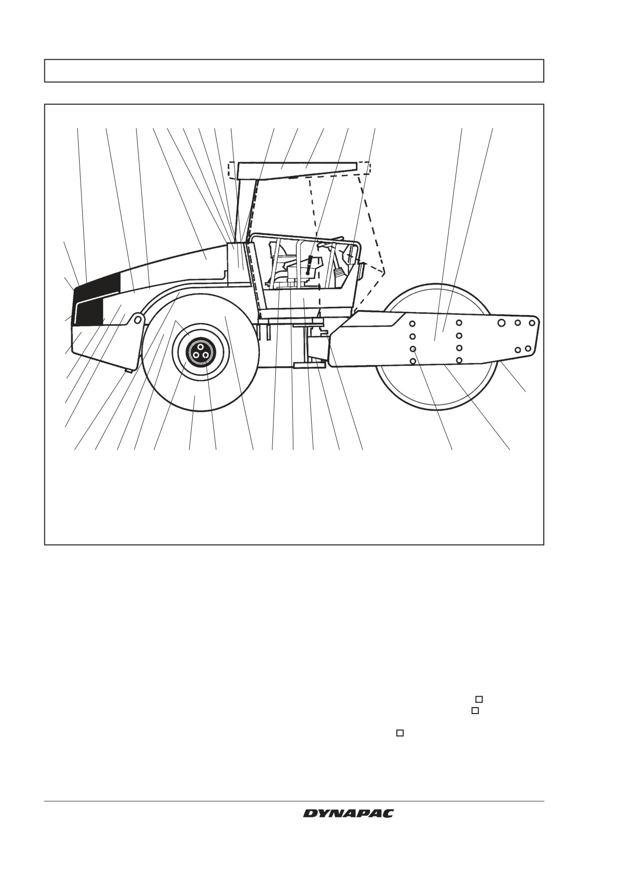
MAINTENANCE SCHEDULE
1
2
3
4
5
6
7
8
9
10
38
39
37
11
12
13
33
32
31
30
29
14
28
27
26
25
24 23 22
21
20
19 36
35 34
18
17
16
15
Fig. 1 Service and maintenance points
1. Radiator grille
14. Scrapers
27. Diesel engine mountings, 4 pcs.
2. Oil level, diesel engine
15. Drum cartridge oil, level plugs, 2 pcs.
28. Feed pump, fuel
3. Fuel filter, initial fuel filter
16. Rubber elements and attachment
29. Diesel fuel, filler
4. Air filter
screws
30. Battery
5. Engine cover, hinges
17. Steering joint
31. Radiator
6. Hydraulic fluid reservoir,
18. Steering cylinders, 2 pcs.
32. Hydraulic fluid cooler
sightglass
19. Flywheel casing, hydraulic pumps
33. Drive belts, cooling, alternator
7. Bleeding filter
20. Wheel nuts
34. Steering chain
8. Hydraulic fluid filters (2 filters)
21. Tires, pressure
35. Seat bearing
9. Drainage, hydraulic fluidreservoir
22. Rear axle, differential
36. Steering chain
10. Hydraulic fluid, filler
23. Rear axle, planetary gears, 2 pcs.
37. Forward/Reverse lever
11. Fuse-box
24. Rear axle suspension, 2 sides
38. Air conditioner
12. Drum cartridge, filling, 2 fillers
25. Oil filter, diesel engine
39. Fresh air filter
13. Drum gearbox
26. Drainage, fuel tank
= Optional
8
CA 262/362/512 M262EN2
MAINTENANCE MEASURES
The periodic measures should be performed primarily
after the specified hours of operation. Use the daily,
weekly, etc. time periods only where this is not
possible.
Remove all dirt before filling, when checking
oils and fuel, and when lubricating with oil or
grease.
The engine manual specifies additional ser-
vice/maintenance instructions which relate to
the diesel engine.
Every 10 hours of operation (Daily)
Item. in
Measure
See page
Comments
fig. 1
Before starting each day
14
Check scraper setting
11, 12
1
Check for free circulation of cooling air
12
31
Check coolant level
12
See engine manual
2
Check diesel engine oil level
13
See engine manual
29
Top up fuel tank
13
6
Check fluid level in hydraulic reservoir
13
38
Check brakes
14
Every 50 hours of operation (Weekly)
Item. in
Measure
See page
Comments
fig. 1
4
Check that hoses and couplings are not leaking15
4
Inspect/clean the filter element in the air cleaner 15
Replace as required
17
Lubricate steering joint
16
18
Lubricate steering cylinders’ attachments
16
20
Check the wheel-nuts are tightened
17
New machine only
21
Check tire pressure
17
38
Inspect the air conditioning
17
Optional
Lubricate the strike-off blade bearings.
18
Optional
After the first 50 hours of operation change only the drum oil and all the oil filters.
CA 262/362/512 M262EN2
9
MAINTENANCE MEASURES
Every 250 hours of operation (Monthly)
Item. in
Measure
See page
Comments
fig. 1
23
Check oil level in rear axle/planetary gearing
19
13
Check oil level in drum gearbox
20
15
Check oil level in the drum cartridge
21
32
Clean the radiators
21
20, 24
Re-tighten bolted joints
22
Applies only to new or
reconditioned component
16
Check rubber elements and screw fasteners
22
30
Check battery
23
Inspect the air conditioning
23
Optional
Every 500 hours of operation (Every three months)
Item. in
Measure
See page
Comments
fig. 1
3
Replace fuel filter
See engine manual
5
Lubricate controls and joints
24
3
Clean the pre-filter
24
25
Change engine oil and oil filter
24
See engine manual
36
Lubricate the steering chain
25
Optional
35
Lubricate the seat bearing
25
Optional
Every 1000 hours of operation (Every six months)
Item. in
Measure
See page
Comments
fig. 1
7
Check bleeder filter on hydraulic reservoir
26
8
Change hydraulic fluid filter
26
9
Drain condensate from hydraulic reservoir
26
26
Drain condensate from fuel tank
27
4
Replace air cleaner main filter
27
22
Change oil in rear axle differential
27
23
Change oil in the rear axle planetary gearing
28
39
Replace the fresh air filter in the cab
29
Optional
Check diesel engine valve clearance
See engine manual
33
Check belt tension for drive belt system
See engine manual
Every 2000 hours of operation (Yearly)
Item. in
Measure
See page
Comments
fig. 1
9, 10
Change fluid in hydraulic reservoir
30
12, 15
Change oil in the drum cartridge
30
13
Change oil in drum gearbox
31
37
Lubricate Forward/Reverse control
31
17
Inspecting the steering joint
31
38
Overhaul air conditioning
32
Optional
10
CA 262/362/512 M262EN2
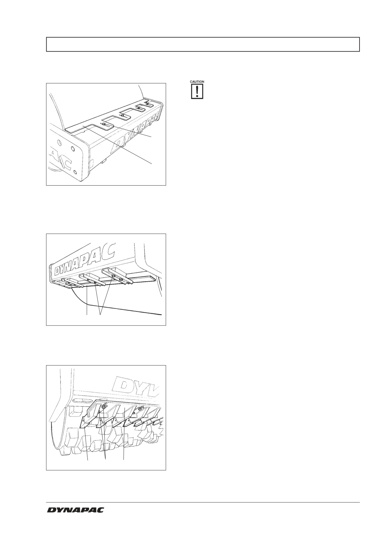
EVERY 10 HOURS OF OPERATION (Daily)
Scrapers
- Checking / Adjustment
It is important to consider movement of the
drum when the machine turns, ie, the scrapers
can be damaged or wear of the drum may
increase if adjustment is made closer than the
values stated.
If necessary, adjust distance to the drum as follows:
2
CA 262
Loosen the screws (2) and adjust the scraper (1) to 20
1
mm from the drum.
Tighten the screws.
Fig. 2
Scrapers
1. Scraper blade
2. Screws (x4)
CA 362/512
Loosen the screws (2) and adjust the scraper (1) to 20
mm from the drum.
Tighten the screws.
Repeat the procedure on the other scraper.
1
2
Fig. 3
Scrapers
1. Scraper blade
2. Screws
CA 262PD/362PD/512PD
Loosen the screws (1), then adjust the beam (2) to 25
mm between the teeth (3) and the drum.
Tighten the screws (1).
3
1
2
Fig. 4
Scrapers
1. Screws
2. Scraper beam
3. Scraper teeth
CA 262/362/512 M262EN2
11
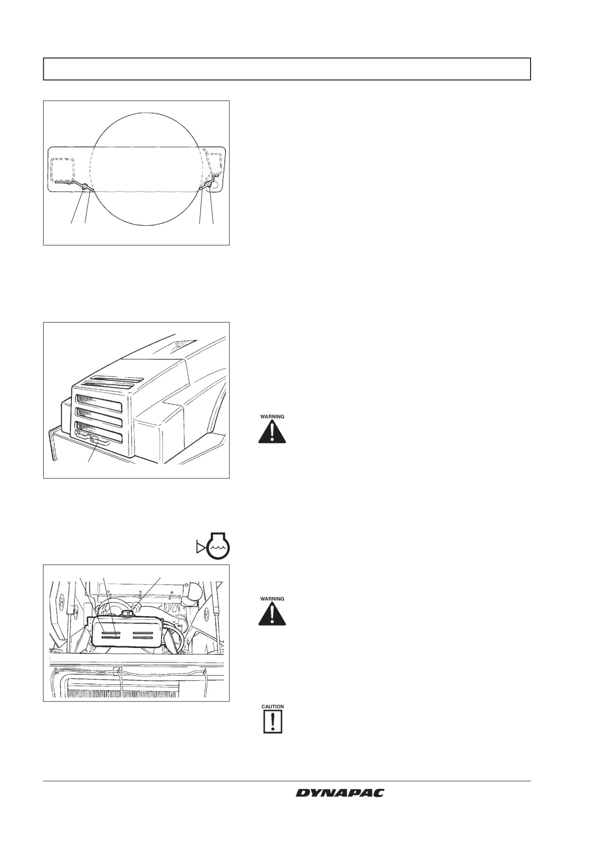
EVERY 10 HOURS OF OPERATION (Daily)
CA 262/362/512 Soft scrapers
Loosen the screws (2) and adjust to light contact
against the drum. Tighten the screws.
2
1
1
2
Fig. 5
Scrapers
1. Scraper blade
2. Screws
Circulation of air - Check
Ensure that the engine has free circulation of cooling air
through the vents in the hood.
To open the engine hood, turn the locking arms upward
(1) and raise the hood to its fully open position, check-
ing that the red safety catch on the left gas spring is
latched.
If the gas-springs of the hood are out of
action and the hood is put at its upper
position - block the hood so that it cannot
fall.
1
Fig. 6
Cooling vents
1. Hood lock
Coolant level - Check
Check that level of the coolant is between the max. and
1
2
3
min. marks.
Danger of scalding. Take great caution if the
radiator cap must be opened while the
engine is hot. Wear protective gloves and
goggles.
Fill with a mixture of 50% water and 50% anti freeze.
See page 3 in these instructions and in the engine
manual.
Fig. 7
Radiator
Flush the system every other year and change
1. Max. level
the coolant. Ensure also that air can flow
2. Min. level
unrestricted through the radiator.
3. Filler cap
12
CA 262/362/512 M262EN2
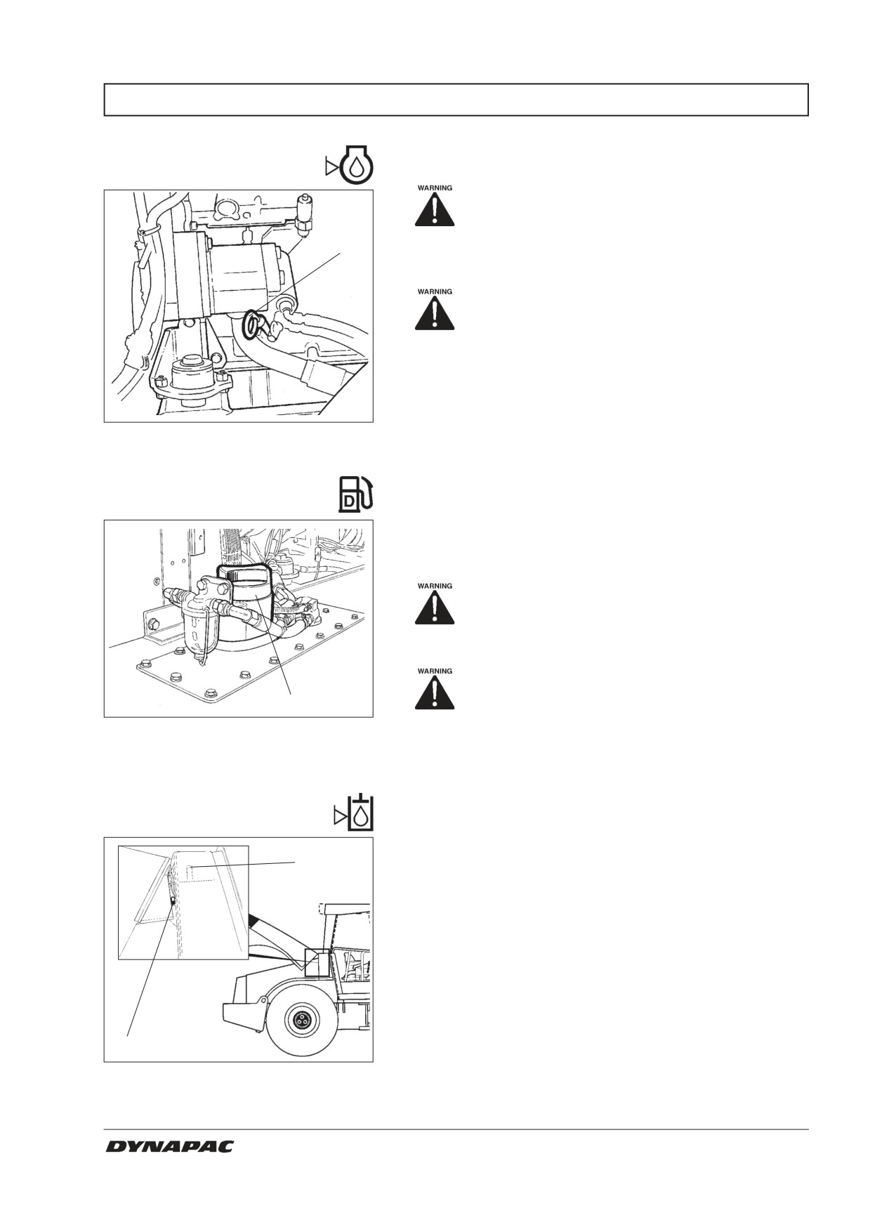
EVERY 10 HOURS OF OPERATION (Daily)
Diesel engine
- Check oil level
Place the roller on a level surface. Switch
the engine off and push in the reserve/
parking brake knob for all checking and
1
adjustments on the roller, unless otherwise
specified.
Danger of burns. Take care not to touch
any hot parts of the engine or the radiator
when removing the dipstick.
The dipstick is located on the engine’s right side.
Pull up the dipstick (1) and check that the oil level is
between the upper and lower marks. For further details,
Fig. 8
Engine compartment
refer to the engine manual.
1. Oil dipstick
Fuel tank - Filling
Refuel daily with diesel fuel up to the lower edge of the
filler pipe (1). Follow the engine manufacturer’s
specification with regard to the quality of diesel fuel.
Switch off the diesel engine. Short-circuit
(press) the filler gun against a non-insula-
ted part of the roller before refuelling, and
against the filler pipe (1) while refuelling.
Never refuel while the engine is running,
1
do not smoke, and avoid spilling fuel.
Fig. 9
Fuel tank
The fuel tank holds 320 litres (84.5 gal).
1. Filler pipe
Hydraulic reservoir
- Check fluid level
Position the roller on a level surface and check that the
2
sight glass reading (1) is between the max. - min.
marks. Top off with hydraulic fluid according to the lu-
bricant specification if the level is too low.
1
Fig. 10
Hydraulic fluid reservoir
1. Sight glass
2. Filler pipe
CA 262/362/512 M262EN2
13
EVERY 10 HOURS OF OPERATION (Daily)
Brake function - Check
1
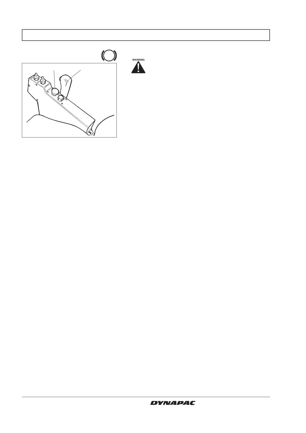
2
Check operation of the brakes as follows:
Drive the roller slowly forward.
Push the reserve/parking brake knob (1); the warning
lamp on the instrument panel should light and the roller
should stop.
After testing the brakes, set the forward/reverse lever
(2) in neutral.
Fig. 11
Control panel
Pull up the reserve/parking brake knob.
1. Reserve/parking brake knob
2. Forward/reverse lever
The roller is now ready for operation.
14
CA 262/362/512 M262EN2
EVERY 50 HOURS OF OPERATION (Weekly)
Air cleaner
- Check/clean
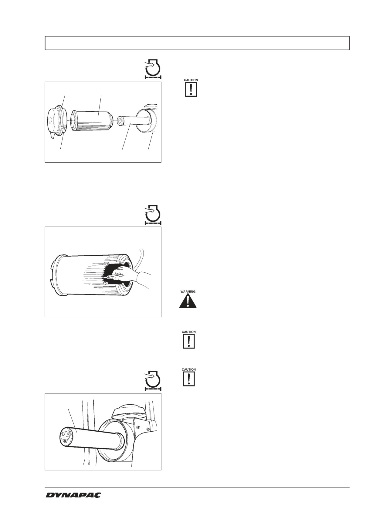
Replace or clean the air cleaner’s main filter if
2
3
the warning lamp on the instrument panel lights
up when the diesel engine is operating at full
speed.
Undo the three locking braces (1). Then pull off the
cover (2) and pull out the main filter (3).
Do not remove the backup filter (4).
1
4
5
Fig. 12
Air cleaner
1. Locking braces
2. Cover
3. Main filter
4. Backup filter
5. Filter housing
Main filter - Cleaning with
compressed air
If the main filter is to be cleaned, compressed air at
max. 5 bar (72 psi) pressure should be used. Blow up
and down along the paper creases on the inside of the
filter.
Hold the nozzle at least 2-3 cm (0.8-1.2 in) away from
the paper creases so that the paper does not tear un-
der the pressure of air.
Use protective goggles when working with
compressed air.
Fig. 13
Main filter
Wipe the inside of the cover (2) and filter housing (5).
Check that the hose clamps between the filter
housing and inlet hose are tightened and that
they do not leak. Check the entire length of the
hose all the way to the engine.
Once the main filter has been cleaned a maxi-
Backup filter
mum of 5 times, it must be replaced.
- Replacement
Replace the backup filter with a new one at every 5th
4
replacement or cleaning of the main filter. The backup
filter cannot be cleaned.
When replacing the backup filter (4), pull out the old fil-
ter from its holder, insert a new one and refit the air
cleaner in the reverse order to the instructions given in
the figure above.
Fig. 14
Air filter
4. Backup filter
CA 262/362/512 M262EN2
15
EVERY 50 HOURS OF OPERATION (Weekly)
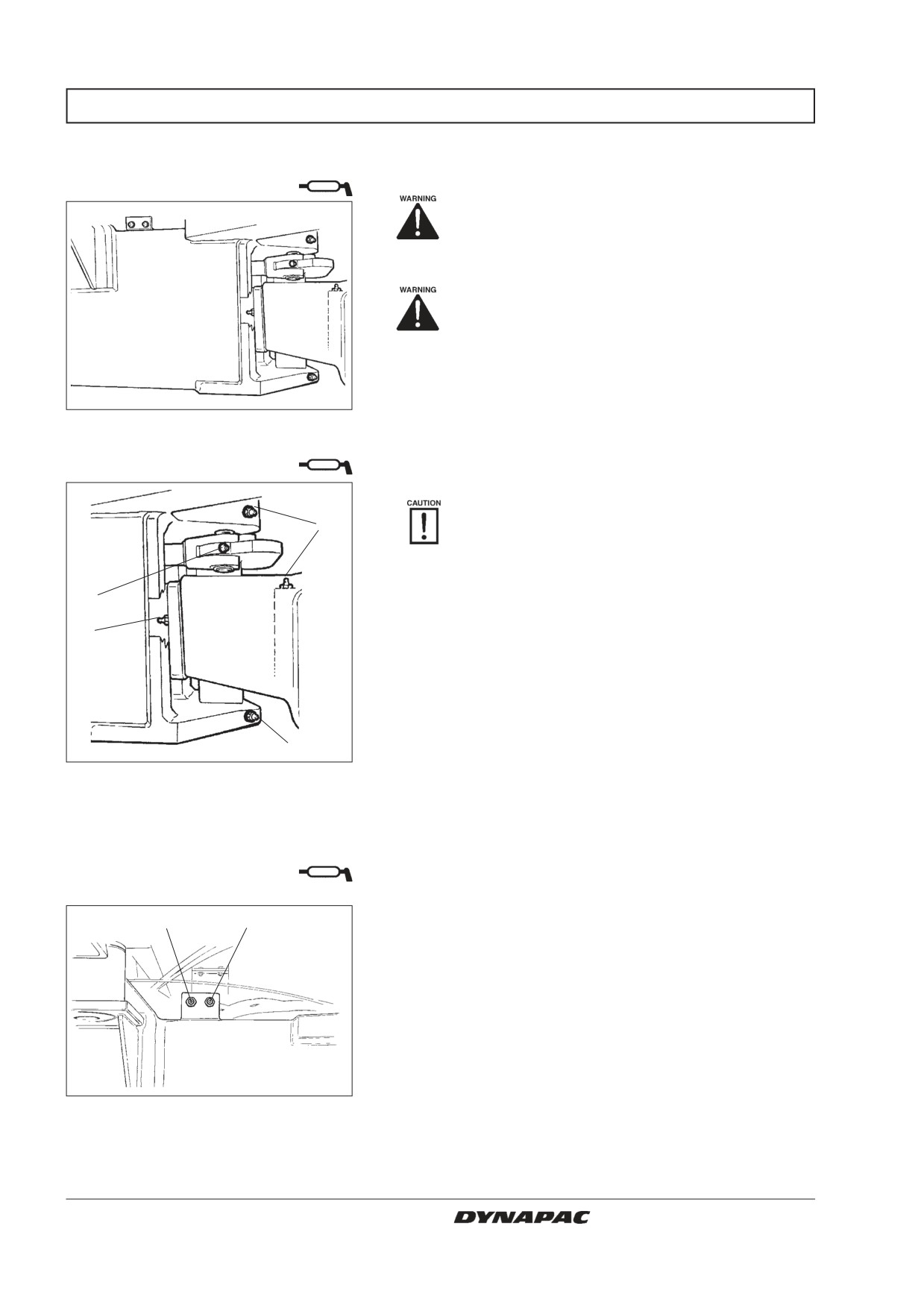
Steering joint/Steering cylinders
- Lubrication
Place the roller on a level surface. Switch the
engine off and push in the reserve/parking
brake knob for all checking and adjustments
on the roller, unless otherwise specified.
Allow no one to get near the steering joint
when the engine is running. Danger of being
crushed when steering is operated. Push
the reserve/parking brake knob before
lubricating.
Turn the steering wheel fully to the left to gain access to
Fig. 15 Steering joint, right side
all lubricating nipples of the steering system on the right-
hand side of the machine (7 on CA 512 and 6 on CA
Steering joint - Lubrication
262-362).
1
Use grease as per the lubricant specification.
Wipe off any dirt and grease from the nipples.
3
Lubricate each nipple (1, 2, and 3) with five strokes of a
manual grease gun. Check that grease penetrates
2
through the bearings.
If grease does not penetrate through the bearings, it
may be necessary to relieve the load on the articulated
joint with a hydraulic jack and then repeat the greasing
process.
1
Fig. 16 Steering joint, right side
1. Lubricating nipples, steering joint (x3)
2. Lubricating nipple, steering joint 512
(on the left side on 262-362)
3. Lubricating nipples, cylinder mount (x1)
Steering cylinder
- Lubrication
Wipe all the nipples clean from dirt and grease.
4
5
Lubricate each nipple (4 and 5) with two strokes of a
grease gun.
Turn the steering wheel fully to the right to gain access
to the front lubricating nipple on the left steering
cylinder and the lubricating nipple on the bearing bush-
ing (CA 262-362). Allow a little grease to remain on the
nipples after lubrication, it will prevent dirt from entering.
Fig. 17 Steering cylinder, right side
4. Lubricating nipple, rear right steering
cylinder mount (x1)
5. Lubricating nipple, rear left steering
cylinder mount (x1)
16
CA 262/362/512 M262EN2
EVERY 50 HOURS OF OPERATION (Weekly)
Tires - Tire pressure
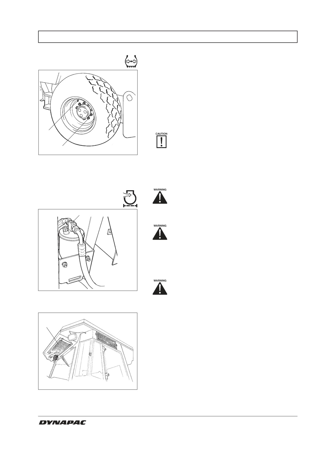
Wheel nuts - Tightening
Check the tire pressures using a pressure gauge.
If the tires are filled with fluid, the air valve (1) must be
in the “12 o’clock” position during pumping.
The relevant tire pressures are given under the heading
“Specifications”.
Check both tires.
1
When changing the tires it is important that
both of them have the same rolling radius. This
2
is necessary to ensure proper functioning of
the anti-slip in the rear axle.
Fig. 18 Wheels
1. Air valve
Check the tightening torque of the wheel nuts (2) at 470
2. Wheel nut
Nm (350 lbf.ft). Check both wheels and all the nuts.
(Applies only to new machine or recently fitted wheels.)
Air conditioning (Optional)
Check the safety manual that accompanies
the roller before filling the tires with air.
- Inspection
1
The system described in this manual is of the ACC
type (Automatic Climate Control)
Never work under the roller with the engi-
ne running. Park on a level surface, chock
the wheels and press the parking brake
control.
Open the engine hood while the unit is running and look
at the sight glass (1) to make sure that no bubbles are
visible on the dryer filter.
Always push the parking brake knob.
Fig. 19
Drying filter
1. Sight glass
The filter is located on the left side in the front of the
engine compartment. If bubbles are visible through the
sight glass, it is a sign that the level of refrigerant is too
low. If so, stop the unit. There is a risk of damage to the
1
unit if it is run with insufficient refrigerant.
In the event of noticeable deterioration of cooling capa-
city, clean the condenser element (1), which is located
at the rear of the cab roof. Also clean the cooling unit
inside the cab.
Fig. 20
Cab
1. Condenser element
CA 262/362/512 M262EN2
17
EVERY 50 HOURS OF OPERATION (Weekly)
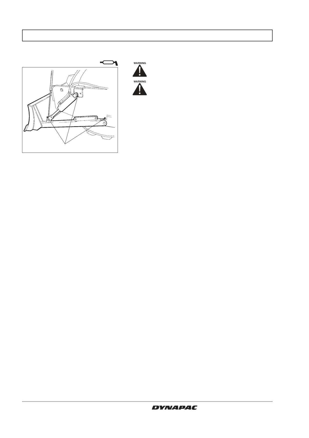
Strike-off blade - Lubrication
(Optional CA262PD)
Always lower the blade to the ground be-
fore leaving or parking the roller.
Make sure that nobody is in the way when
operating the blade.
Lower the blade.
Wipe the nipples clean from grease and dirt, three on
each side of the machine.
Grease each nipple (1) with four strokes of the grease
gun. Ensure that grease penetrates the bearings.
1
Fig. 21
Strike-off blade
1. Lubricant nipples
18
CA 262/362/512 M262EN2
EVERY 250 HOURS OF OPERATION (Monthly)
Rear axle differential
- Check oil level
Never work under the roller with the engi-
ne running. Park on a level surface. Block
the wheels securely.
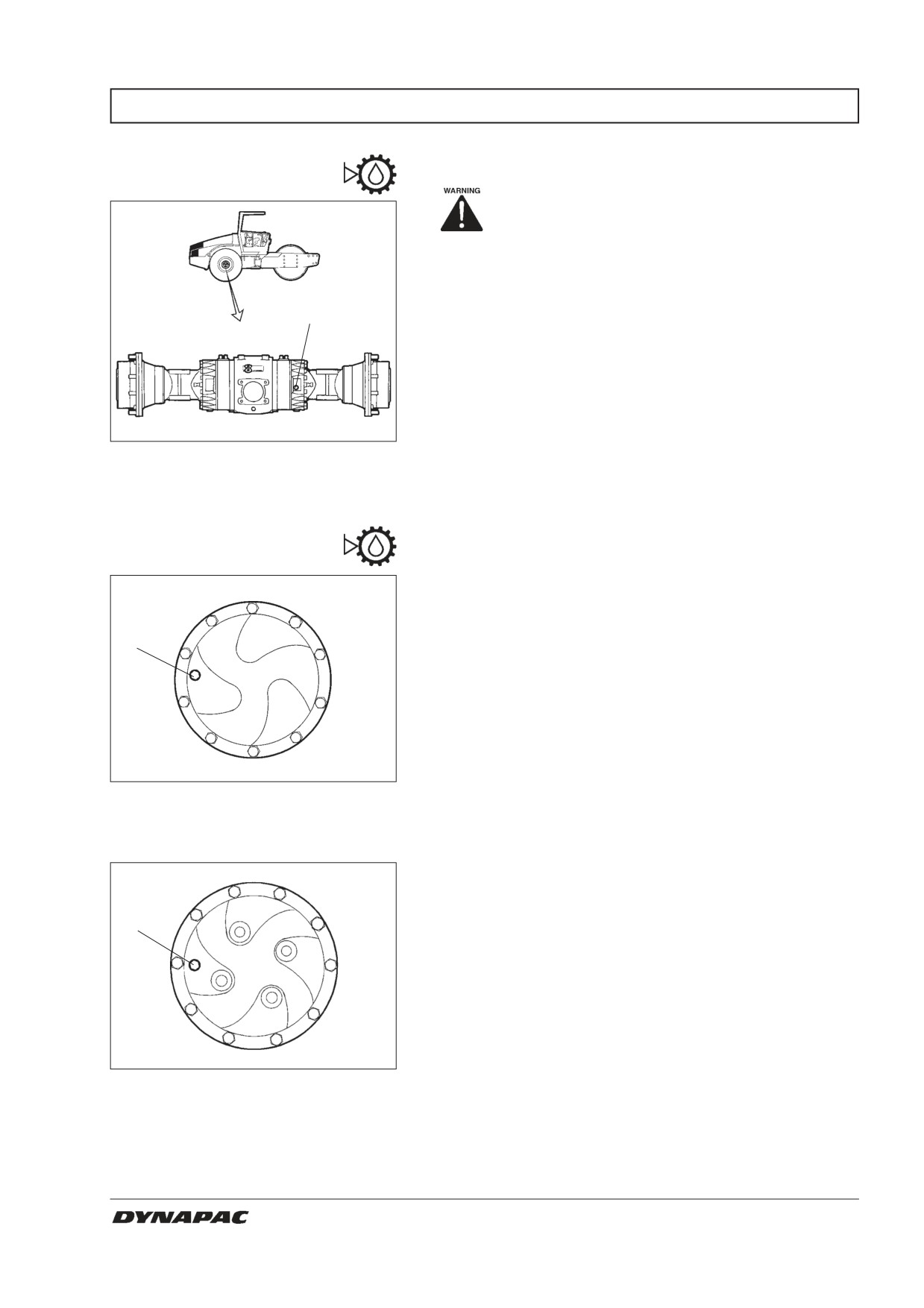
Wipe clean and remove the level plug (1) and check
that the oil level reaches the lower edge of the plug
1
hole. Top off with oil to the right level if the level is low.
Use transmission oil according to the lubricant
specification.
Fig. 22 Oil level check - differential housing
1. Oil level/Filler plug
Rear axle planetary gears
- Check oil level
Position the roller with the level plug (1) in the planetary
gears at 9 o’clock.
Wipe clean and remove the level plug (1) and check that
1
the oil level reaches the lower edge of the plug hole. Top
off with oil to the right level if the level is low. Use trans-
mission oil according to the lubricant specification.
Check the oil level in the same way in the rear axle’s
other planetary gear.
Fig. 23 Oil level check - planetary gear
(CA 262-362 Std.)
1. Oil level/Filler plug
1
Fig. 24
Oil level check - planetary gear
(CA 512 std) (CA 262-362 optional)
1. Oil level/Filler plug
CA 262/362/512 M262EN2
19
EVERY 250 HOURS OF OPERATION (Monthly)
Drum gearbox
- Check oil level
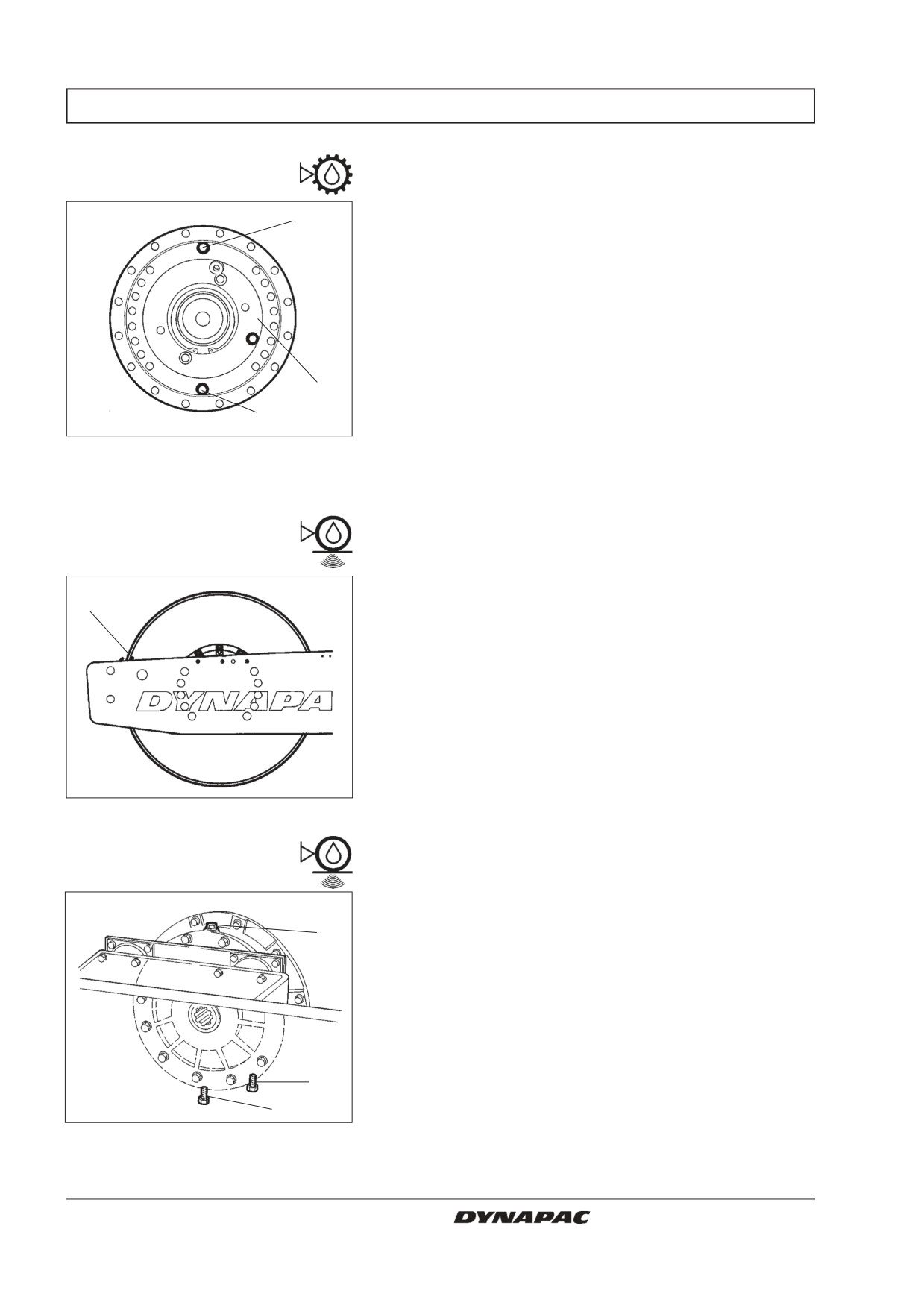
Wipe clean the area around the plug (1) and then undo
2
the plug.
Ensure that the oil level reaches up to the lower edge of
the plug hole.
Top off with oil to the right level if the level is low. Use
transmission oil according to the lubricant specification.
Position the roller with the filler plugs (2) straight up.
1
3
Clean and screw in the plugs tightly.
Fig. 25 Oil level check - Drum gearbox
1. Oil level plug
2. Filler plug
3. Drainplug
Drum cartridge
- Checking the oil level
Position the machine level so that the indicator pin (1)
1
on the inside of the drum is aligned with the top of the
drum frame.
Fig. 26
Left side of drum
1. Indicator pin
Drum cartridge
- Checking the oil level
Wipe the filling plug and level plug clean from dirt.
Unscrew the filling plug (1)
1
3
2
Fig. 27
Roller, right-hand side
1. Filler plug
2. Drain plug
3. Level plug
20
CA 262/362/512 M262EN2
EVERY 250 HOURS OF OPERATION (Monthly)
Drum cartridge
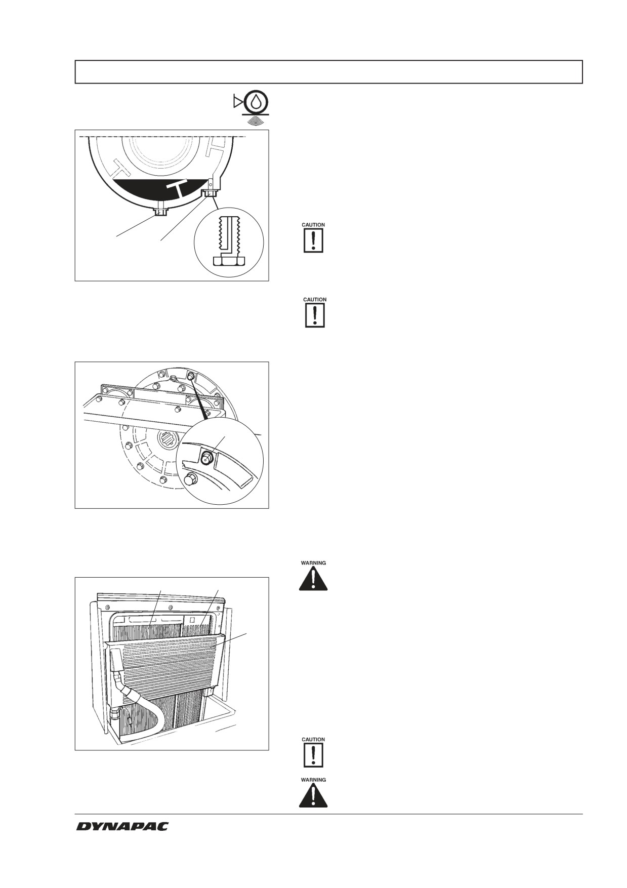
Then unscrew the level plug (3) at the bottom of the
cartridge until the hole in the middle of the plug
becomes visible.
Top off with oil through the filling plug (1), until oil begins
to run out from the level-plug hole. The level is correct
when it stops running.
Ensure that only MOBIL SHC 629 is used in
2
3
the cartridges.
Clean and refit the plugs. Repeat the procedure on the
opposite side.
Fig. 28
Drum cartridge
2. Drain plug
Do not overfill with oil - risk for overheating.
3. Level plug
Drum cartridge
- Cleaning the ventilation screw
Clean the drum ventilation hole. The hole is required to
eliminate excess pressure inside the drum.
1
Fig. 29
Drum
1. Ventilated screw
Radiator
- Check/clean
Place the roller on a level surface. Switch
1
2
the engine off and push in the reserve/
parking brake knob for all checking and
adjustments on the roller, unless otherwise
specified.
3
Check that air can flow freely through the radiators (1),
(2) and (3).
A dirty radiator should be blown clean with compressed
air, or alternatively cleaned with a high-pressure washer.
Blow or wash the cooler in the opposite direction to that
of the cooling air.
Be careful when using a high-pressure washer
- do not place the nozzle too close to the
Fig. 30
Engine room
radiator.
1. Water cooler
2. Intercooler
Use protective goggles when working with
3. Hydraulic fluid cooler
compressed air or a high-pressure washer.
CA 262/362/512 M262EN2
21
EVERY 250 HOURS OF OPERATION (Monthly)
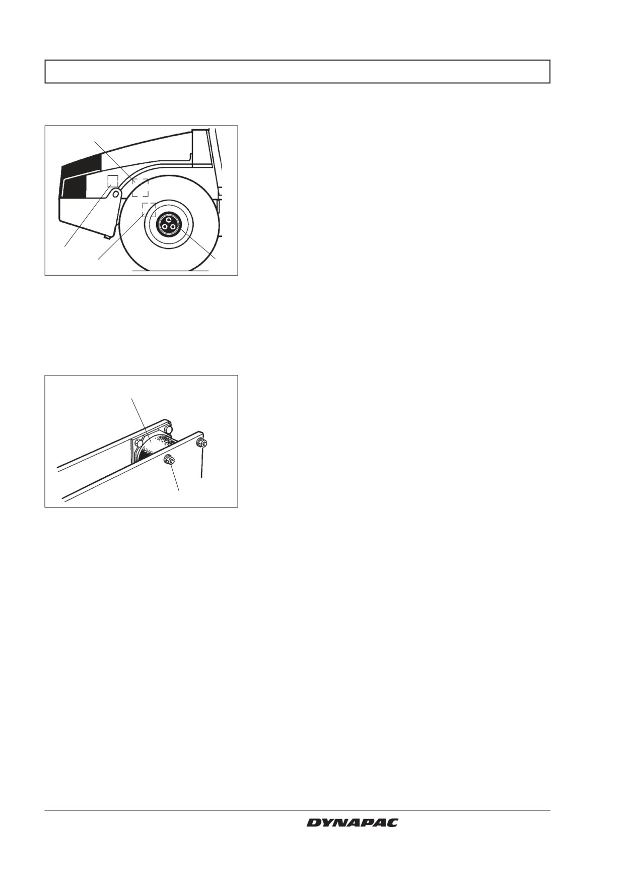
Bolted joints
- Checking tightening torque
Rear axle suspension (2) 330 Nm (243 lbf.ft), oiled.
1
Steering pump against engine (1) 38 Nm (28 lbf.ft).
Engine suspension (3). Check that all M12 bolts (x20)
are tightened, 78 Nm (57 lbf.ft).
Wheel nuts (4). Check that all nuts are tightened, 470
Nm (347 lbf.ft), oiled.
3
(The above applies to new or replaced components
2
4
only.)
Fig. 31
Right side of machine
1. Steering pump
2. Rear axle
3. Engine suspension
4. Wheel nuts
Rubber elements and screw
fasteners - Check
Check all the rubber elements (1), and replace them all if
1
more than 25% of the elements on the same side of the
roller have cracks deeper than 10-15 mm (0.4-0.6 in).
Use a knife blade or other pointed tool when carrying
out this check.
Check also that the screw fasteners (2) are tightened.
2
Fig. 32
Roller, vibration side
1. Rubber element
2. Screw fasteners
22
CA 262/362/512 M262EN2
EVERY 250 HOURS OF OPERATION (Monthly)
Battery
- Check electrolyte level
Make sure there are no open flame in the
1
2
3
1
vicinity when checking the electrolyte level.
An explosive gas is formed in the battery
during the charging process.
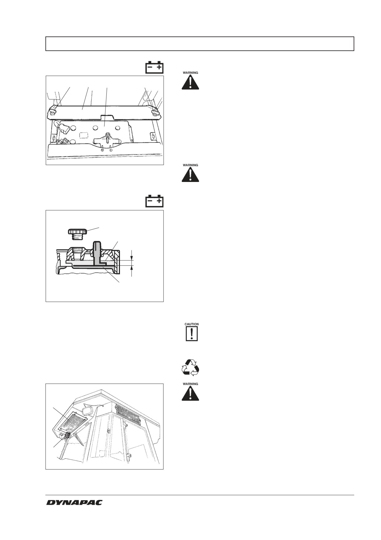
Lift up the engine compartment cover and undo the
quick-release screws (1).
Raise the battery cover (2).
Dry the upper face of the battery.
Fig. 33
Battery box
Use protective goggles. The battery con-
1. Quick-release screws
tains corrosive acid. In the event of con-
2. Battery cover
tact, rinse with water.
3. Battery
Battery cell
Remove the cell covers and check that the fluid level is
about 10 mm (0.4 in) above the plates. Check the level
1
in all the cells. If the level is lower, top up to the correct
level with distilled water. If the ambient air temperature
2
is below freezing point, the engine should be run for a
while after the distilled water is added, otherwise there
is a risk that the water might freeze.
10 mm
Check that the ventilation holes in the cell covers are
not blocked, then refit the covers.
3
The cable terminals must be properly tightened and
clean. Corroded cable connections should be cleaned
Fig. 34
Electrolyte level in battery
1. Cell cover
and greased with alkaline Vaseline.
2. Electrolyte level
3. Plate
When disconnecting the battery, always
disconnect the negative cable first. When
connecting the battery, always connect the
positive cable first.
Discard used batteries properly. Batteries
Air conditioning (Optional)
contain lead, which is detrimental to the envi-
ronment.
- Inspection
Before doing any electric welding on the
machine, disconnect the battery ground
cable and then all electrical connections to
2
the alternator.
Inspect refrigerant hoses and connections and make
sure that there are no signs of oil film that could indicate
leakage of refrigerant.
1
Fig. 35
Air conditioning
1. Refrigerant hoses
2. Condenser element
CA 262/362/512 M262EN2
23
EVERY 500 HOURS OF OPERATION (Every three months)
Controls and moving
joints - Lubrication
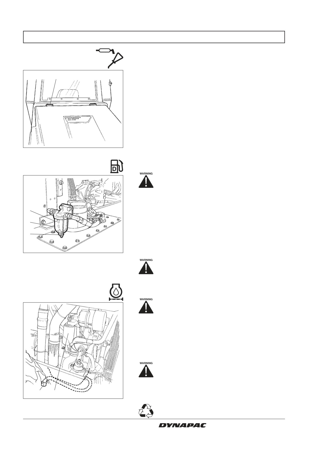
Lubricate engine hood hinges (1) and the slide rails of
1
the operator’s seat with grease, other joints and
controls with oil. Lubricate the cab hinges with grease.
See lubricant specification.
Fig. 36
Engine hood
1. Hinge
Prefilter - Cleaning
Place the roller on a level surface. Switch
the engine off and push in the reserve/
parking brake knob for all checking and
adjustments on the roller, unless otherwise
specified.
3
Loosen the screw (1) and remove the glass bowl (2).
2
Take out the strainer (3) and clean using a non-
1
flammable fluid. Reinstall the strainer and the bowl.
Start the engine and check that the pre-filter does not leak.
Fig. 37
Engine
1. Screw
Make sure there is adequate ventilation
2. Glass bowl
(extraction) if the diesel engine is run in-
3. Strainer
doors. Risk of carbon monoxide poisoning.
Diesel engine
- Changing the filter and oil
Position the roller on a level surface. Stop
the engine and apply the parking brake/
reserve brake.
The oil drain plug (1) is most easily accessible from
underneath the engine. It is fitted on a tube to the rear
axle. Drain the oil when the engine is warm. Place a
receptacle for at least 15 litres (16 qts) underneath the
drain plug.
Danger of being scalded when draining off
hot oil. Protect your hands.
Change the engine oil filter (2) at the same time.
1
2
See also the engine manual.
Fig. 38
Left side of engine
1. Drain plug
Dispose of the drained oil and filter in an
2. Oil filter
approved manner.
24
CA 262/362/512 M262EN2
EVERY 500 HOURS OF OPERATION (Every three months)
Steering chain and
Seat bearing - Lubrication
Optional on rollers without cab
a
Remember that the chain is a vital part of the
steering mechanism.
1
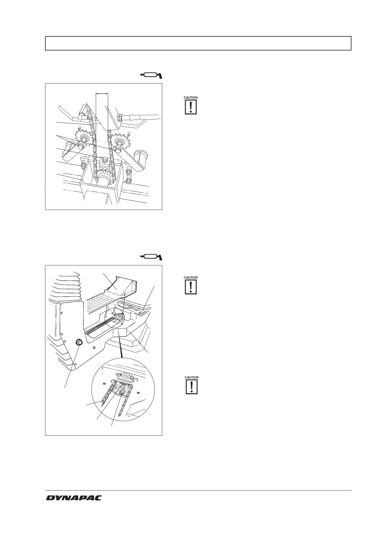
Clean and lubricate the chain (1) between the seat
2
bearing and steering valve with grease. The chain is
accessible underneath the platform.
3
It is not necessary to remove the chain.
4
5
Adjust the chain as follows if it has slackened so that
size “a” is less than 30 mm (1.2 in): Loosen the nuts (4)
and adjust the mount (5) backwards with the adjusting
nut (3) until size “a” is 50 mm (2 in).
Fig. 39
Underneath operator’s position
1. Steering chain
2. Chain-tightening device
3. Adjusting nut
4. Nuts
5. Control valve mount
Seat bearing - Lubrication
Optional on rollers without cab
5
6
Remember that the chain is a vital part of the
steering mechanism.
Remove the cover (5) to gain access to the lubrication
nipple (1).
Lubricate the slew bearing of the operator’s seat with
three strokes of a hand-operated grease gun.
Lubricate the seat locking latch (7), accessible from
below.
7
Also grease the slide rails of the seat (6).
If the seat begins to bind when resetting, it
4
needs to be lubricated more often.
3
Clean and grease the chain (3) between the seat and
the steering column.
2
If the chain becomes slack on the cogwheel (2), loosen
1
the screws (4) and move the steering column forward,
tighten the screws and check the tension of the chain.
Fig. 40
Seat bearing
1. Lubrication nipple
2. Cogwheel
3. Steering chain
4. Adjusting screw
5. Cover
6. Slide rails
7. Slew interlock
CA 262/362/512 M262EN2
25
EVERY 1000 HOURS OF OPERATION (Every six months)
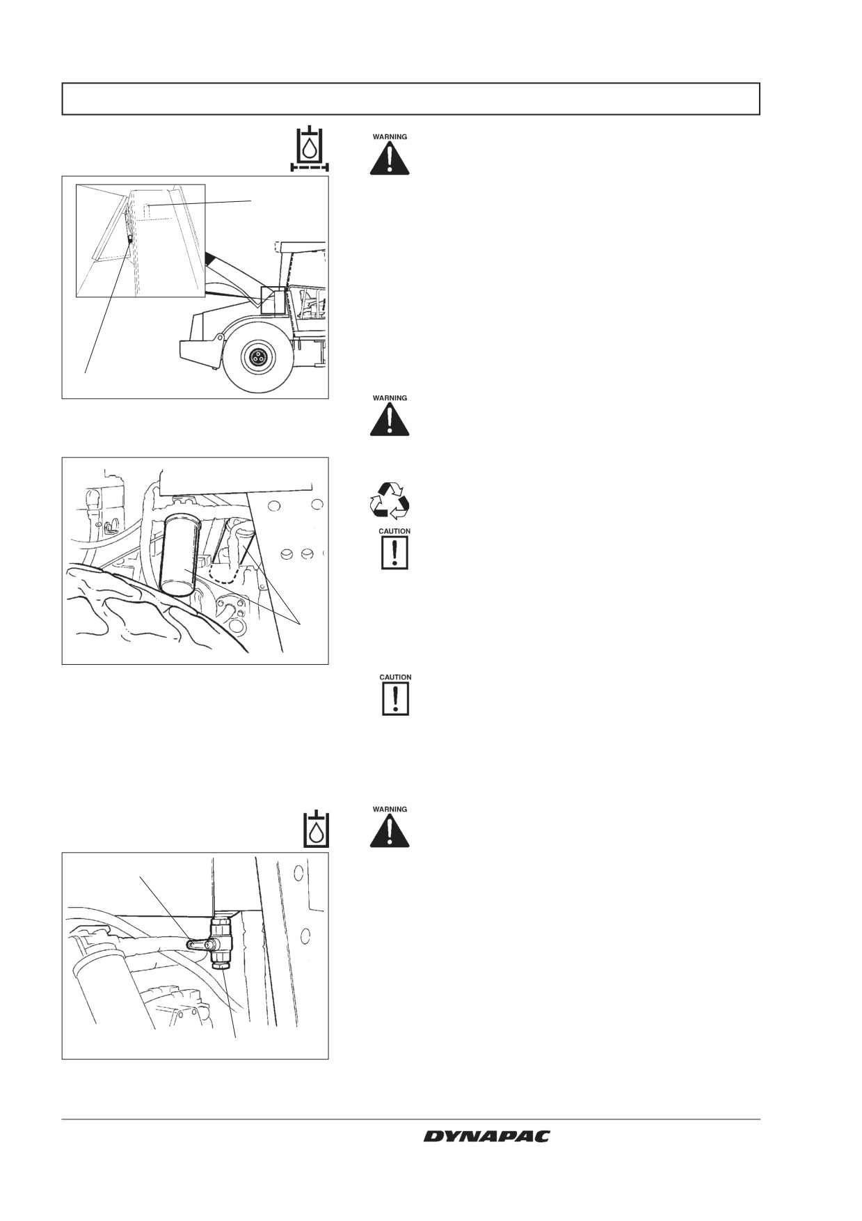
Hydraulic fluid filter
Place the roller on a level surface. Switch
- Change
the engine off and push in the reserve/
parking brake knob for all checking and
adjustments on the roller, unless otherwise
2
specified.
Undo the cover/bleeder filter (2) on top of the reservoir
so that over-pressure inside the reservoir can be elimi-
nated.
Check that the bleeder filter (2) is not blocked - air
should flow freely through the cover in both directions.
If there is a blockage in either direction, clean the filter
with a little diesel oil and blow through with compressed
air until the blockage disappears, or replace the cover
3
with a new one.
Fig. 41
Hydraulic fluid reservoir
Always use protective goggles when work-
2. Filler cover/bleeder filter
ing with compressed air.
3. Sight glass
Clean thoroughly around the oil filters.
Remove the oil filters (1) and dispose of them
in an approved manner. They are single-use
filters and cannot be cleaned.
Check that the old sealing rings do not remain
stuck on the filter holders, otherwise this might
give rise to oil leakage between the old and
new seals.
Clean the filter holder sealing surfaces thoroughly.
1
Apply a thin film of hydraulic fluid on the seals of the
new filter. Screw on the filter by hand.
Fig. 42
Engine compartment
First tighten the filter until its seal is in contact
1. Hydraulic fluid filters (x2)
with the filter attachment. Then turn an addi-
tional half revolution. Do not over-tighten the
filter as this might damage the seal.
Start the engine and ensure that there is no leakage of
hydraulic fluid from the filters. Check level of fluid in the
sight glass (3) and top up as required.
Hydraulic reservoir
Make sure there is adequate ventilation
(extraction) if the diesel engine is run in-
- Drainage
doors. Risk of carbon monoxide poisoning
1
Condensate in the hydraulic reservoir is removed via
the drainage tap (1).
Drainage should be performed when the roller has been
standing for a long period of time, for example over-
night. Drain as follows:
Remove the plug (2).
Place a container under the tap.
Open the tap (1) and let any trapped condensate run out.
2
Shut the drainage tap.
Fig. 43 Hydraulic reservoir, underside
1. Drainage tap
Refit the plug.
2. Plug
26
CA 262/362/512 M262EN2
EVERY 1000 HOURS OF OPERATION (Every six months)
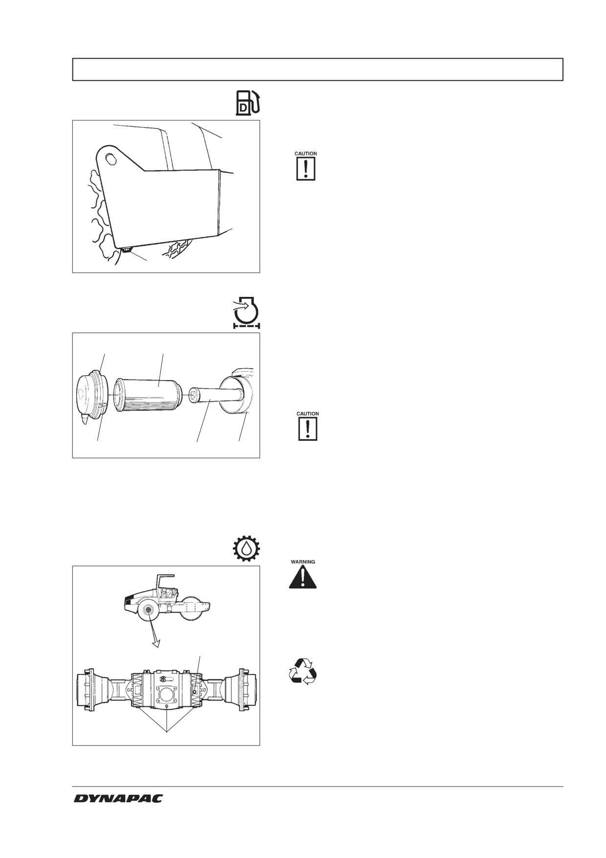
Fuel tank - Drainage
Water and sediment in the fuel tank are removed via
the drainage plug in the bottom of the fuel tank.
Be very careful during draining. Do not drop
the plug or else all the fuel will flow out.
Drainage should be performed when the roller has been
standing for a long period of time, for example over-
night. The fuel level should be as low as possible.
The roller should preferably have been standing with
this side somewhat lower, so that water and sediment
1
will gather near the drainage plug (1). Drain as follows:
Fig. 44 Fuel tank
1. Drainage plug
Place a container under the plug (1).
Air filter - Replacement
Undo the plug and drain off the water and sediment until
only clean diesel fuel appears through the plug opening.
2
3
Refit the plug.
Replace the main filter (3) of the air cleaner even if it
has not yet been cleaned five times, see under 50
hours for filter replacement.
If a clogged filter is not replaced the exhaust
fumes will be black and the engine will loose
power. There will also be danger of severe
1
4
5
damage to the engine.
Fig. 45 Air cleaner
1. Locking braces
2. Cover
3. Main filter
4. Backup filter
5. Filter housing
Rear axle differential
- Oil change
Never work under the roller with the engi-
ne running. Park on a level surface and
block the wheels securely.
Wipe clean and remove the level/filler plug (1) and all
three drain plugs (2) and drain the oil into a suitable
receptacle. The volume is almost 12 litres (12.7 qts).
1
Save the oil and deposit it in an approved
manner.
Refit the drainage plugs and top up with fresh oil until
the correct level is reached.
Note: It takes a while for the oil to flow into the axle. Do
2
not fill the entire volume all at once.
Fig. 46 Rear axle
Refit the oil-level/filler plug. Use transmission oil, see
1. Oil level/Filler plug
the lubrication specification.
2. Drainage plugs
CA 262/362/512 M262EN2
27
EVERY 1000 HOURS OF OPERATION (Every six months)
Rear axle planetary gears
- Oil change
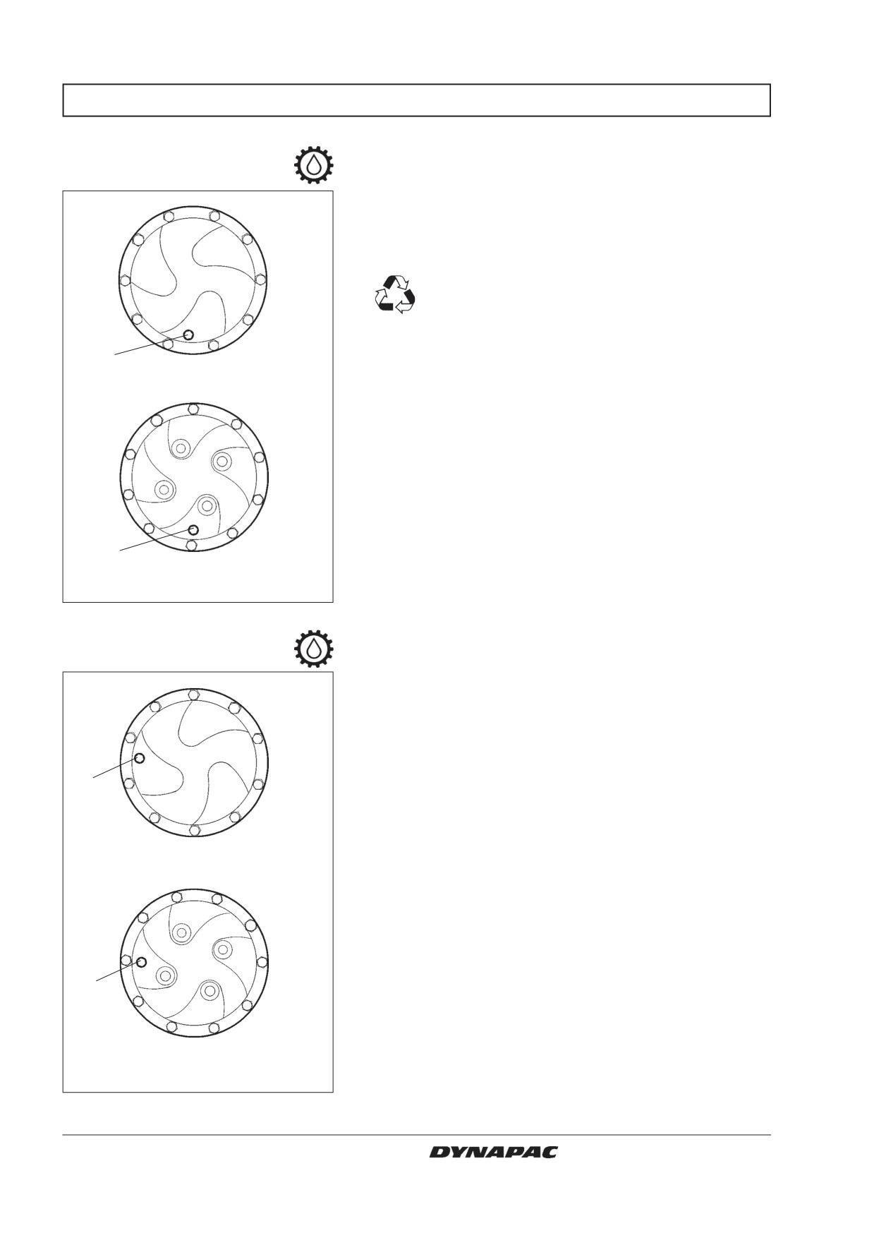
Position the roller with the plug (1) at its lowest position.
Wipe clean, unscrew the plug (1) and drain the oil into a
suitable receptacle. The volume is about 2 litres (2.1 qts).
Save the oil and deposit it in an approved
manner.
1
CA 262-362 Std.
1
CA 512
(CA 262/362 Optional)
Fig. 47 Planetary gear/drainage position
1. Plug
Position the roller with the plug at 9 o’clock.
Fill with oil to lower edge of level hole.
Refit the plug and repeat the process on the other side.
Use transmission oil. See the lubrication specification.
1
CA 262-362 Std.
1
CA 512
(CA 262/362 Optional)
Fig. 48 Planetary gear/filling position
1. Plug
28
CA 262/362/512 M262EN2
EVERY 1000 HOURS OF OPERATION (Every six months)
Fresh air filter - Replacement
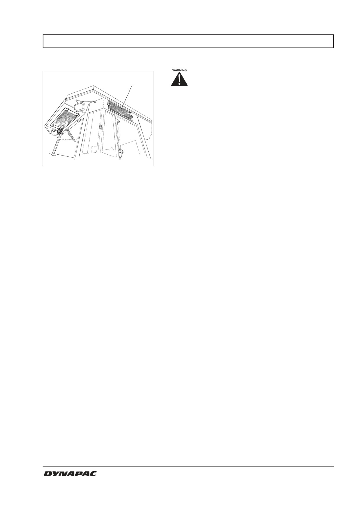
Use a stepladder to reach the filter (1).
1
As an alternative the filter can be reached
via the cab window on the right side.
Loosen the two screws (2) at the rear of the cab roof.
Take down the whole holder and remove the filter
insert.
Replace with a new filter.
It may be necessary to replace the filter more often if
the machine is used in a dusty environment.
Fig. 49
Cab
1. Fresh air filter
2. Screw (x2)
CA 262/362/512 M262EN2
29
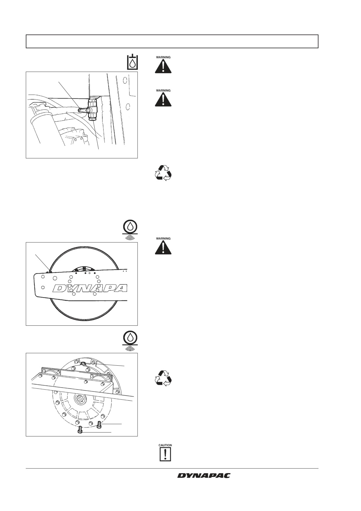
EVERY 2000 HOURS OF OPERATION (Yearly)
Hydraulic reservoir
Place the roller on a level surface. Switch the
– Fluid change
engine off and push in the reserve/parking
brake knob for all checking and adjustments
1
on the roller, unless otherwise specified.
Danger of being burned when draining hot
oil. Protect your hands.
Obtain a container for collecting the used fluid. The con-
tainer should have a volume of at least 60 litres (16 gal).
A suitable container may be an empty oil drum or similar
item which is placed beside the roller. The fluid then
runs in a hose from the drainage plug (1) to the oil drum,
2
after the plug (2) has been removed and the tap opened.
Fig. 50
Hydraulic reservoir, underside
1. Drainage tap
Save the oil and deposit it in an approved
2. Plug
manner.
Fill up with fresh hydraulic fluid as per the instructions
under the heading “Hydraulic reservoir - Check fluid
level”.
Replace the hydraulic fluid filters at the same time.
Start the diesel engine and operate the various hydraulic
Drum cartridge
functions.
- Oil change
Make sure there is adequate ventilation
(extraction) if the diesel engine is run in-
1
doors.
(Risk of carbon monoxide poisoning)
Check the fluid level and top up if necessary.
Position the machine level so that the indicator pin (1)
on the inside of the drum is aligned with the top of the
drum frame.
Fig. 51
Left side of drum
1. Indicator pin
Place a receptacle for about 5 litres (5.3 qts)
underneath the drain plug (2).
1
Save the oil and deposit it in an approved
manner.
Clean and unscrew the filler plug (1) and the drain plug
(2). Allow all of the oil to drain off. Fit the drain plug, and
fill with fresh synthetic oil according to instructions
under the heading “Drum cartridge - checking the oil
3
level”.
2
Repeat the procedure on the opposite side.
Fig. 52
Right side of the drum
1. Filler plug
Ensure that only MOBIL SHC 629 is used in
2. Drain plug
the cartridges..
3. Level plug
30
CA 262/362/512 M262EN2
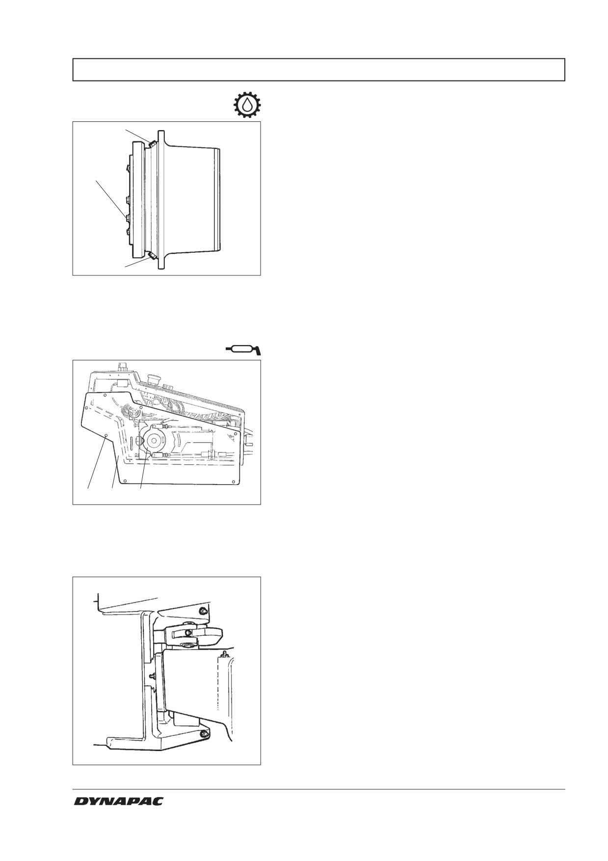
EVERY 2000 HOURS OF OPERATION (Yearly)
Drum gearbox
- Changing the oil
Place the roller on a level surface with the plugs (1) and
2
(2) as illustrated.
Wipe clean, unscrew the plugs (1, 2 and 3) and drain
the oil into a suitable receptacle, capacity about 3.5
3
liters (3.7 qts).
Refit the plug (1) and fill with oil up to the level plug (3),
according to “Drum gearbox - Checking the oil level”.
Use transmission oil, see Lubricant Specification.
1
Clean and refit the level plug (3) and filler plug (2).
Fig. 53
Drum gearbox
1. Drain plug
2. Filler plug
3. Level plug
Forward/Reverse lever
- Lubrication
Unscrew the screws (1) and remove the plate (2).
Grease the contact surface of the cam disc (3).
Refit the plate (2) with the screws (1).
1
2
3
Fig. 54
Forward/Reverse lever
1. Screw
2. Plate
3. Cam disk
Steering joint - Check
Inspect the steering joint to detect any damage or
cracks.
Check and correct any loose bolts.
Check also for any stiffness and play.
Fig. 55
Steering joint
CA 262/362/512 M262EN2
31
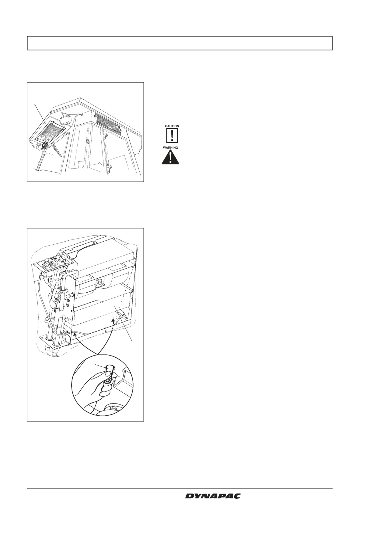
EVERY 2000 OPERATING HOURS (Yearly)
Air conditioning (Optional)
- Overhaul
Regular inspection and maintenance are necessary to
ensure satisfactory long-term operation.
1
Clean the condenser element (1) free from dust with
the aid of compressed air. Blow from above.
The air jet could damage the flanges of the
elements if it is too powerful.
Wear protective goggles when working
with compressed air.
Inspect the fastening of the condenser element.
Fig. 56
Cab
1. Condenser element
Clean the cooler unit and the cooling elements (1) free
from dust with the aid of compressed air.
Inspect the system hoses for chafing. Make sure that
drainage from the cooling unit is unobstructed so that
condensation does not accumulate inside the unit.
Check the drain by squeezing the valves (2)
underneath the cab.
1
2
Fig. 57
Aircondition
1. Cooling element
2. Drain valve (x2)
32
CA 262/362/512 M262EN2
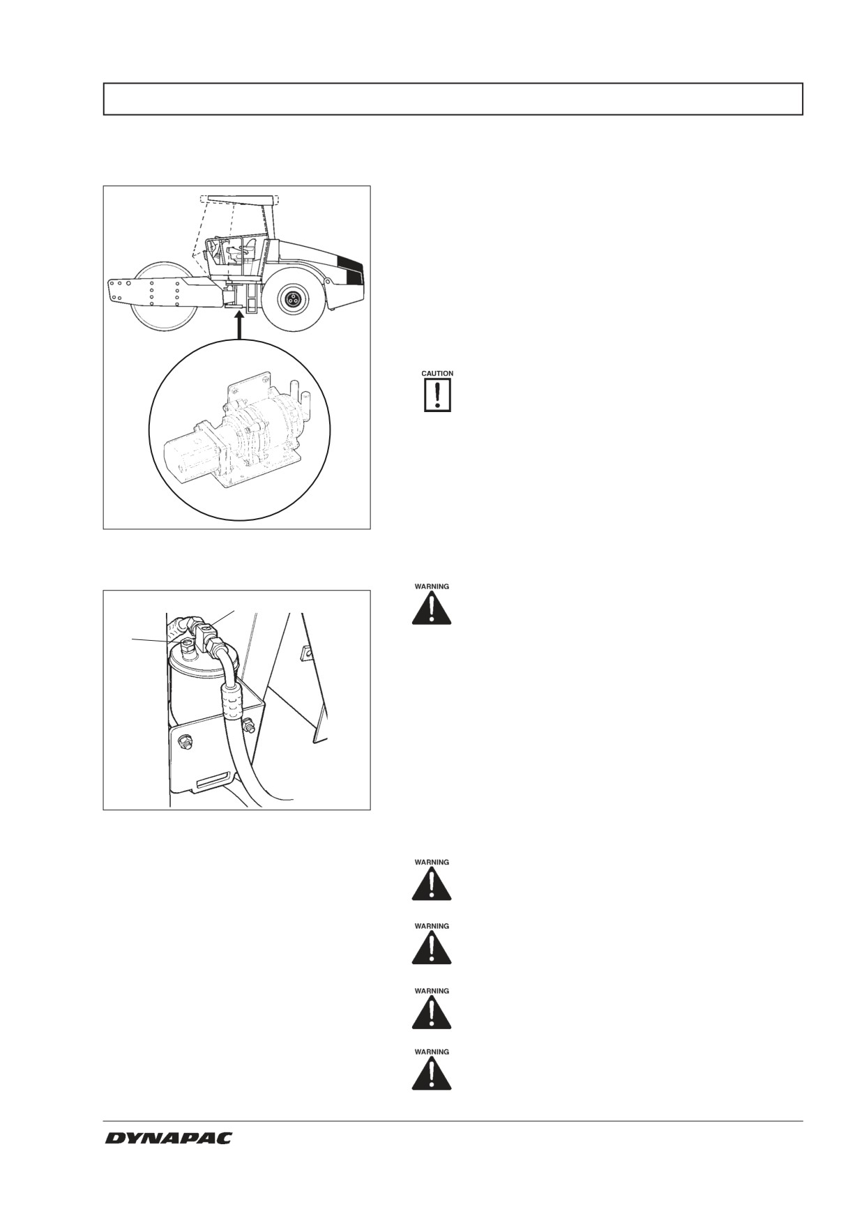
EVERY 2000 OPERATING HOURS (Yearly)
Compressor - Inspection
(Optional)
Inspect the compressor and hydraulic motor
fastenings.
These are located under the cab between the rear
sides of the frame. The components are accessible
from below.
The unit should be run at least five minutes every
week, if possible, to ensure lubrication of rubber
gaskets in the system.
The air unit should not be run when the
outdoor temperature is below 0°C (32°F).
Fig. 58
Compressor
Drying filter - Inspection
Never work under the roller with the engi-
1
ne running. Park on a level surface, chock
the wheels and press the parking brake
2
control.
Open the engine hood while the unit is operating and
check in the sight glass (1) that no bubbles are visible
on the dryer filter. If bubbles are visible through the
sight glass, it is a sign that the level of refrigerant is too
low. If so, stop the unit. There is a risk of damage to the
unit if it is run with insufficient refrigerant.
Check the moisture indicator (2). The color should be
Fig. 59
Drying filter in engine compartment
blue; if it is beige the dryer cartridge must be replaced
1. Sight glass
by an authorized service company.
2. Moisture indicator
The compressor will be damaged if the unit
is run with too little refrigerant.
Do not disconnect the hose coupling.
The cooling system is pressurized.
Incorrect handling can result in serious
personal injuries.
The system contains pressurized refriger-
ant. Releasing refrigerants into the air is
prohibited. The refrigerant circuit may only
be repaired by an authorized company.
CA 262/362/512 M262EN2
33
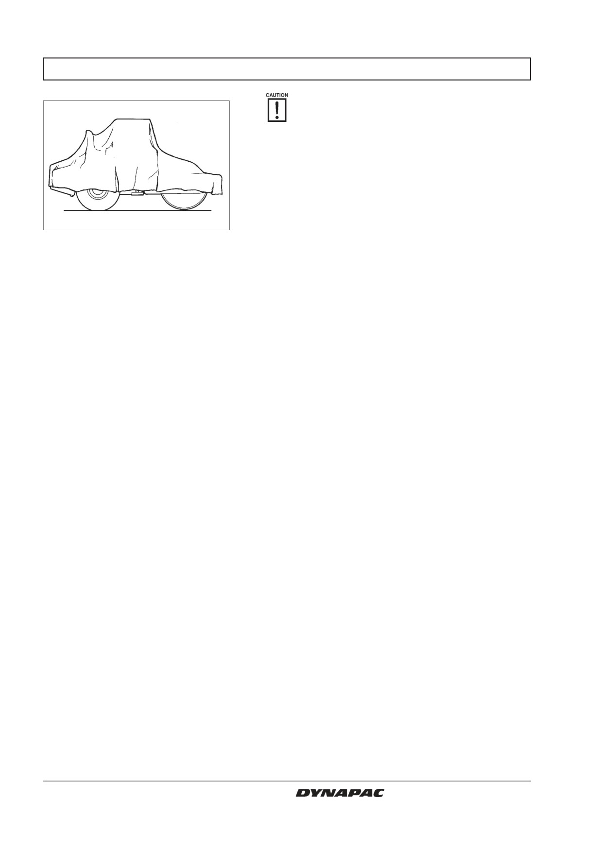
LONG-TERM STORAGE
For long-term storage (longer than one month),
the following instructions should be followed.
These instructions apply for storage lasting up
to 6 months.
Before re-commissioning the roller, the points
marked with an asterisk * must be restored.
Fig. 60 Protecting the roller from the
elements
Diesel engine
See the manufacturer’s instructions in the engine
instruction manual, which is supplied together with
the roller.
Battery
Remove the battery from the roller, clean it’s
exterior, check its electrolyte level and recharge it
once a month.
Cover the air cleaner or its opening with plastic or
Air cleaner, exhaust pipe
tape, and cover also the exhaust pipe’s opening.
This is done so as to prevent moisture from
penetrating into the engine.
Fuel tank
Fill the fuel tank completely to prevent condensation.
Hydraulic reservoir
Drain off any condensation water and fill the hydrau-
lic reservoir to the upper mark.
Lubricate the steering joint bearings and the steering
Steering cylinder, hinges etc.
cylinder’s two bearings with grease.
Grease the steering cylinder’s piston with
conservation grease.
Grease also the engine compartment cover’s hin-
ges, the seat slide rails, the engine-speed control
and the forward/reverse control mechanism.
Tires (All-weather)
Check that tire pressure is 110 kPa (1,1 kp/cm2),
(16 psi).
Covers, tarpaulin
*
Place the instrument cover on the steering column.
Cover the entire machine with a tarpaulin, which
should hand some way off the ground. If possible,
store the roller indoors, preferably in a building with a
uniform temperature.
34
CA 262/362/512 M262EN2
SPECIAL INSTRUCTIONS
Standard lubricants and other
Upon delivery from the factory, the various systems
and components are filled with the oils specified see
recommended oils
lubricant specification and they can be used at ambient
temperatures from -10°C to +40°C (14°F - 104°F).
A maximum temperature of +35°C (95°F)
applies for biological hydraulic fluid.
When operating in hotter ambient temperatures, but up
to max. +50°C (122°F), the following instructions apply:
Higher ambient temperature
The diesel engine can handle this temperature with the
standard oil, but the following oils must be used in the
max. +50°C (122°F)
other components:
Hydraulic system with mineral fluid: Shell Tellus TX100
or corresponding.
Other components using transmission oil:
Shell Spirax HD 85W/140 or corresponding.
Temperatures
The temperature limits apply for a roller with standard
features.
Rollers with extra equipment such as noise suppress-
ers etc. may require additional attention at the upper
temperatures.
When washing the machine, do not direct the
High-pressure washing
jet of water directly at the fuel or hydraulic fluid
tank covers. This is particularly important
when using a high-pressure washing unit.
Do not spray water directly on electric components or
the instrument panel. Put a plastic bag over the filler
cap of the fuel tank and secure with a rubber band.
This will prevent water from entering the venting hole in
the filler cap. This could otherwise cause operational
disturbance, for example, a clogged filter.
Extinguishing fires
If there is a fire in or on the machine, it is best to use an
ABE-class fire extinguisher. However, a BE-class CO2
extinguisher is also suitable.
If the roller is equipped with a protective structure
ROPS, protective cab
(ROPS, Roll Over Protective Structure), or protective
cab, never subject the structure or cab to welding or
drilling. Never attempt to repair a damaged structure or
cab; they must be replaced with new ones.
When an auxiliary starter battery is used, always
Starting assistance
connect the positive terminal on the auxiliary battery to
the positive terminal on the roller’s battery, and
negative to negative.
CA 262/362/512 M262EN2
35
ELECTRICAL SYSTEM, FUSES, RELAYS
Fuses and relays
The electrical regulating and control system is
protected against overload by 27 fuses and 12 relays.
The number depends on how much extra equipment is
fitted on the machine.
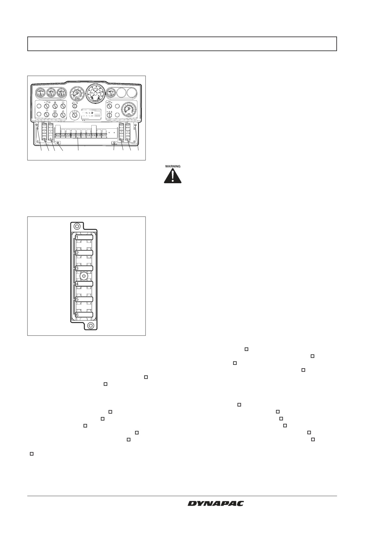
The four fuse boxes (1,2,3,4) and the relays are
located behind the lower instrument plate, which can be
removed by turning the four quick-screws (5) a ¼-turn.
The machine is equipped with a 12 V electrical system
5 1 2 5
6
5
3 4 5
and an alternator.
Fig. 61
Instrument panel
Connect the battery to the correct polarity
1,2,3,4. Fuse boxes
5. Quick-screws
(- to ground). The cable between battery
6. Relays
and alternator must not be disconnected
when the engine is running.
Fuses on the machine
The figure shows the rating and function of the different
fuses.
All fuses are flat pin fuses.
The tachograph and memory for the radio are protected
at the battery master disconnect switch by a 10A fuse.
Fig. 62
Fuse box, left side (1)
Fuse box, right side (3)
7.5A
1. Brake valve, starter relay, hourmeter
20A
1. Working lights, left
7.5A
2. VBS relay
20A
2. Working lights, right, instrument illumination
7.5A
3. Indicating panel
7.5A
3. Headlight, left
7.5A
4. Horn
7.5A
4. Headlight, right, instrument illumination*
7.5A
5. Low/High speed/Strike-off blade
5. -
3A
6. Reversing alarm
6. -
Fuse box, left side (2)
Fuse box, right side (4)
7.5A
1. Instrumentation
10A
1. Hazard beacon
3A
2. Compaction meter
10A
2. Direction indicators, main fuse
7.5A
3. Hazard beacon
7.5A
3. Position light, left, front and rear
7.5A
4. Anti-spin
5A
4. Position light, right, front and rear
15A
5. Windscreen wiper, utility cab
5A
5. Direction indicator, left, front, rear and side
5A
6. Interior lighting, utility cab
5A
6. Direction indicator, right, front, rear and side
= Optional
* When driving lights are fitted
36
CA 262/362/512 M262EN2
ELECTRICAL SYSTEM, FUSES, RELAYS
Fuses in the cab
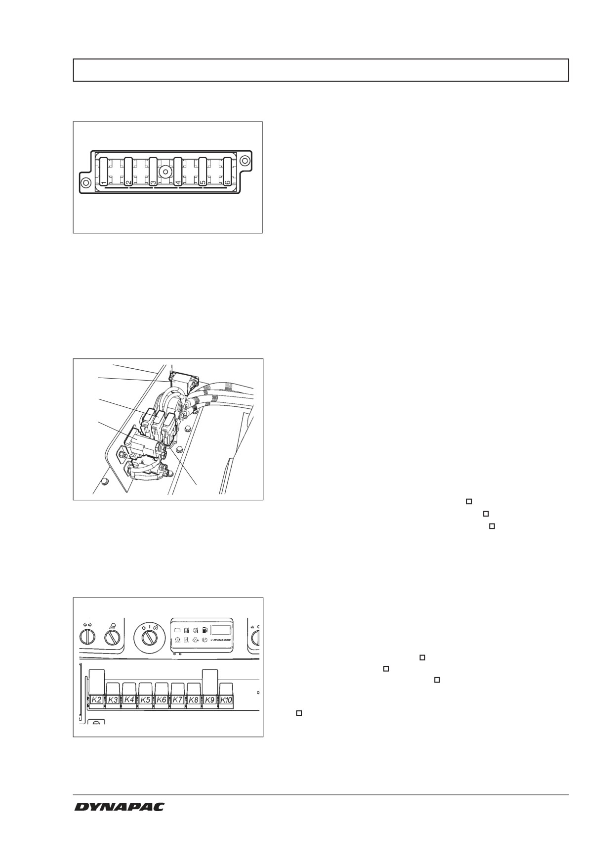
The electric system in the cab is equipped with its own
fuse box, located overhead at the front right part of the
cab.
The figure shows the ampere rating and function of the
different fuses. All fuses are of the flat pin type.
Fig. 63
Fuse box overhead in cab
20A
1. Condenser fans, cab roof
10A
2. Radio
5A
3. Cab interior lighting
25A
4. Air conditioner fan
10A
5. Rear screen wiper/screen-wash
10A
6. Front screen wiper/screen-wash
Main fuses
There are three main fuses (2). These are located
1
behind the battery master disconnect switch. The three
screws need to be unscrewed to remove the plastic
2
cover.
3
The fuses are of the flat pin type.
The starter relay (1), preheater relay (3) and fuses for
the preheater relays (4) are also fitted here.
4
Supply, standard
30 A (Green)
Supply, cab
50 A (Red)
Fig. 64
Engine compartment
Supply, lighting
40 A (Orange)
1. Starter relay
Preheater supply relay 125 A (Orange)
2. Main fuses
3. Preheater relay
4. Fuses for preheater
Relays
K2
VBS relay
K3
Main relay
K4
Horn relay
K5
Hourmeter relay
K6
Fuel level relay
K7
Reverse alarm relay
K8
Lights relay
K9
Direction indicator relay
K10
Brakes relay
= Optional
Fig. 65
Instrument panel
CA 262/362/512 M262EN2
37
ELECTRICAL SYSTEM, FUSES, RELAYS
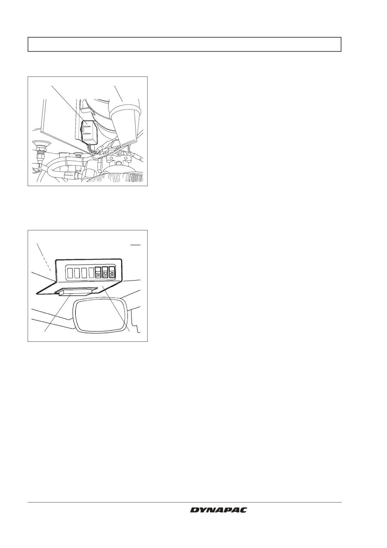
Control box
The control box (1) automatically regulates preheating
1
2
of the diesel engine, ie, the box receives its activating
signal from a temperature sensor on the engine intake
pipe.
Fig. 66 Engine compartment
1. Control box for engine preheater
2. Air cleaner
Relays in cab
Unscrew the instrument plate (1) to replace the relays
2, 3
for air conditioner fan and condenser fan on the cab
roof, and radio.
4
1
Fig. 67
Cab roof, front
1. Instrument plate
2. K30 Relay for air conditioner fan
3. K31 Relay for condenser fans + radio
4. Fuse box
38
CA 262/362/512 M262EN2