DYNAPAC Vibratory roller CC 422/422C/CC 422HF/CC 422CHF/CC 432, CC 522/522C/CC 522HF/522CHF. Operation & Maintenance (2003)
DYNAPAC
CC 422/422C/CC 422HF/422CHF
CC 432
CC 522/522C/CC 522HF/522CHF
MAINTENANCE
M422EN5
Box 504, SE-371 23 Karlskrona, Sweden
Telephone
+46 455 30 60 00
Telefax
+46 455 30 60 30
Web www.dynapac.com
Vibratory roller
CC 422/422C/CC 422HF/CC 422CHF/CC 432
CC 522/522C/CC 522HF/522CHF
Maintenance
M422EN5, August 2003
Diesel engine:
Cummins B 3.9 TAA
These instructions apply from:
CC 422
PIN (S/N) *42520422*
CC 422C
PIN (S/N) *42620427*
CC 422HF
PIN (S/N) *43520423*
CC 422CHF PIN (S/N) *43620429*
CC 432
PIN (S/N) *42720433*
CC 522
PIN (S/N) *42920523*
CC 522C
PIN (S/N) *43020527*
CC 522HF
PIN (S/N) *43720522*
CC 522CHF PIN (S/N) *43820526*
The Dynapac CC 422 is a vibratory roller in the 10-tonne class, with articulated
steering and with propulsion, brakes and vibration on both drums.
The above roller is also available in a so-called Combi version with model designation
CC 422C. It weighs about 9 tonnes and has a vibratory drum at the front and four
smooth rubber tyres at the rear; all with drive and braking functions.
CC 432 is a vibratory roller in the 11-ton class, with articulated steering and
vibration on both drums.
CC 522 is the designation of this model, the biggest roller in the series. It features wider
and larger diameter drums compared with the CC 422 and is in the 12 tonne class.
This roller is also available in a combi version, weighing about 11 tons and
with model designation CC 522C.
Reservation for changes.
Printed in Sweden.
CONTENTS
Page
Lubricants and symbols
3
Technical specifications
4-7
Maintenance schedule
8
Maintenance measures
9, 10
Every 10 hours of operation (Daily)
11-16
Every 50 hours of operation (Weekly)
17-20
Every 250 hours of operation (Monthly)
21, 22
Every 500 hours of operation (Every three months) . 23-27
Every 1000 hours of operation (Every six months) . 28, 29
Every 2000 hours of operation (Yearly)
30-34
Long-term storage
35
Special instructions
36
Electrical system, fuses
37-39
WARNING SYMBOLS
Safety instructions - Personal safety
Special caution - Machine or component damage
GENERAL
Read the entire manual before starting any
service work.
Make sure that ventilation (extraction) is
adequate if the engine is run indoors.
The machine must be cared for properly to ensure
satisfactory operation. Keep the machine clean to
facilitate quick and timely detection of any leakage, loose
bolts and loose connections.
Make a habit each day, before starting up, of checking the
roller to detect any leakage or damage. Also check the
ground underneath the roller, where it is most often easier
to detect any leakage.
TAKE CARE OF THE ENVIRONMENT! Do not
CALIFORNIA
leave behind any oil, fuel or other substances
that are detrimental to the environment.
Proposition 65 Warning
This manual contains instructions for periodic measures
Diesel engine exhaust and some of its
that should normally be performed by the operator.
constituents are known to the State of
The manufacturer’s instructions noted in the
California to cause cancer, birth defects,
engine manual also apply. This is placed under a
and other reproductive harm.
separate flap in the product folder for the roller.
2
CC 422/HF/422C/CHF - CC 432 - CC 522/HF/522C/CHF M422EN5
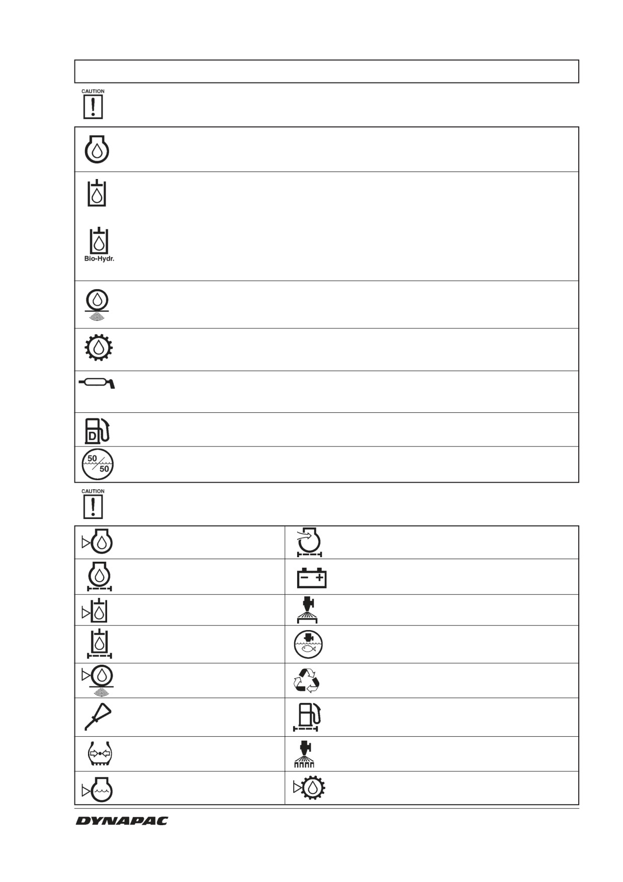
LUBRICANTS AND SYMBOLS
Always use high-quality lubricants in the recommended amounts. Too much grease or oil can
cause overheating and subsequent increased wear.
ENGINE OIL
ambient temperature
Shell Rimula SAE 15W/40 or equivalent.
-10°C-+40°C (14°F-104°F) API CF-4/SG (CD/CE)
HYDRAULIC FLUID
ambient temperature
-10°C to +40°C (14°F-104°F) Shell Tellus TX68 or equivalent
above +40°C (above 104°F) Shell Tellus TX100 or equivalent
BIOLOGICAL
Shell Naturelle HF-E46
HYDRAULIC FLUID
When it leaves the factory, the machine may be filled
with biologically degradable fluid. The same type of
fluid must be used when changing or topping off.
DRUM OIL
ambient temperature
-15°C to +40°C (5°F-104°F) Mobil SHC 629 or equivalent
TRANSMISSION OIL
ambient air temperature
Shell Spirax SAE 80W/90, HD API, GL-5
-15°C - +40°C (5°F - 104°F)
GREASE
SKF LGHB2 (NLGI Class 2) or equivalent for the
articulated joint.
Shell Retinax LX2 or equivalent for other grease points.
FUEL
See engine manual.
COOLANT
GlycoShell or corresponding.
mixed 50/50 with water
Anti-freeze protection down to about -41°C (-106°F).
Other fuel and lubricants are required for operation in extremely high or extremely low
ambient temperature. See the “Special instructions” chapter, or consult Dynapac.
Engine, oil level
Air filter
Engine, oil filter
Battery
Hydraulic reservoir, level
Sprinkler
Hydraulic fluid filter
Sprinkler water
Drum, oil level
Recycling
Lubricating oil
Fuel filter
Air pressure
Sprinkler, tyres
Coolant, level
Transmission, oil level
CC 422/HF/422C/CHF - CC 432 - CC 522/HF/522C/CHF M422EN5
3
TECHNICAL SPECIFICATIONS
Weights & dimensions
CC422/HF
CC422C/CHF CC432
Operating mass with ROPS, EN500, kg (lbs) 10400 (22,932)
9950 (21,940)
11900 (26,240)
Operating mass without ROPS, kg (lbs)
10000 (22,050)
9550 (21,058)
11500 (25,358)
Operating mass with cab, kg (lbs)
10400 (22,932)
9950 (21,940)
11900 (26,240)
Length, standard equipped roller, mm (in)
4950 (195)
4950 (195)
4950 (195)
Width, standard equipped roller, mm (in)
1810 (71)
1810 (71)
1810 (71)
Width, with cab, mm (in)
2025 (80)
2025 (80)
2025 (80)
Height, without cab (Shipping height), mm (in) 2170 (85)
2170 (85)
2170 (85)
Height, with cab, mm (in)
2970 (117)
2970 (117)
2970 (117)
Height, with AC, mm (in)
2970 (117)
2970 (117)
2970 (117)
Height, with AC and hazard beacon, mm (in)
3295 (130)
3295 (130)
3295 (130)
Weights & dimensions
CC522/HF
CC522C/CHF
Operating mass with ROPS, EN500, kg (lbs) 11850 (26,129)
11000 (24,255)
Operating mass without ROPS, kg (lbs)
11450 (25,247)
10600 (23,373)
Operating mass with cab, kg (lbs)
11850 (26,129)
11000 (24,255)
Length, standard equipped roller, mm (in)
5090 (200)
5090 (200)
Width, standard equipped roller, mm (in)
2090 (82)
2090 (82)
Width, with cab, mm (in)
2160 (85)
2160 (85)
Height, without cab (Shipping height), mm (in) 2240 (88)
2240 (88)
Height, with cab, mm (in)
3040 (120)
3040 (120)
Height, with AC, mm (in)
3040 (120)
3040 (120)
Height, with AC and hazard beacon, mm (in)
3365 (132)
3365 (132)
Fluid volumes, Litres
CC422/HF CC422C/CHF CC432
CC522/HF CC522C/CHF
Drum (qts)
14 (14.8)
14 (14.8)
6 (6.3)
14 (14.8)
14 (14.8)
Hydraulic reservoir (qts)
40 (42.3)
40 (42.3)
40 (42.3)
40 (42.3)
40 (42.3)
Fuel tank (gal)
200 (52.8)
200 (52.8)
200 (52.8)
200 (52.8)
200 (52.8)
Emulsion tank (gal)
-
485 (128)
-
-
485 (128)
Water tank (gal)
485 (128)
485 (128)
485 (128)
485 (128)
485 (128)
Diesel engine, lubr. oil (qts)
11 (11.6)
11 (11.6)
11 (11.6)
11 (11.6)
11 (11.6)
Transmission (qts)
0,8 (0.9)
0,8 (0.9)
0,8 (0.9)
0,8 (0.9)
0,8 (0.9)
Diesel engine, coolant (qts)
7,9 (8.4)
7,9 (8.4)
7,9 (8.4)
7,9 (8.4)
7,9 (8.4)
4
CC 422/HF/422C/CHF - CC 432 - CC 522/HF/522C/CHF M422EN5
TECHNICAL SPECIFICATIONS
Electrical system
Battery
12 V 170 Ah
Alternator
12 V 95A
Fuses
5, 7,5, 15, 20 och 25 Ampére
Vibrationsdata
CC422/HF
CC422C/CHF
CC432
CC522/HF
CC522C/CHF
Static linear load, (kg/cm)
Front:
30,7/30,7
30,7/30,7
35,1
30,2/30,2
30,2
Rear:
31,2/31,2
-
35,7
30,6/30,6
-
Amplitude, (mm)
High:
0,8/0,7
0,8/0,7
0,6
0,67/0,59
0,67/0,59
Low:
0,4/0,28
0,4/0,28
0,3
0,34/0,24
0,34/0,24
Frequency, (Hz)
At High amplitude:
49/49
49/49
49
49/49
49/49
At Low amplitude:
49/62
49/62
49
49/62
49/62
Centrifugal force, (kN)
At High amplitude:
128/111
128/111
133
128/111
128/111
At Low amplitude:
65/72
65/72
68
65/72
65/72
Vibrationsdata
CC422/HF
CC422C/CHF
CC432
CC522/HF
CC522C/CHF
Static linear load, (pli)
Front:
171.9/171.9
171.9/171.9
196.6
169.1/169.1
169.1
Rear:
174.7/174.7
-
199.9
171.4/171.4
-
Amplitude, (in)
High:
0.031/0.028
0.031/0.028
0.024
0.026/0.023
0.026/0.023
Low:
0.016/0.011
0.016/0.011
0.012
0.013/0.009
0.013/0.009
Frequency, (vpm)
At High amplitude:
2940/2940
2940/2940
2940
2940/2940
2940/2940
At Low amplitude:
2940/3720
2940/3720
2940
2940/3720
2940/3720
Centrifugal force, (lb)
At High amplitude:
28,800/24,950
28,800/24,950
29,925
28,800/24,950
28,800/24,950
At Low amplitude:
14,625/16,186
14,625/16,186
15,287
14,625/16,186
14,625/16,186
Traction
CC422/HF CC422C/CHF CC432
CC522/HF CC522C/CHF
Speed range, km/h (mph)
0-11 (0-7)
0-11 (0-7)
0-11 (0-7) 0-12 (0-7.5)
0-12 (0-7.5)
Climbing ability (theoretical) %
42
47
36
34
34
Tires
CC422C/CHF
CC522C/CHF
Tire dimension
E20 (13/80 R20) Lisse
E20 (13/80 R20) Lisse
Tire pressure(kPa)
200 (2,0 kp/cm²), (29 psi)
200 (2,0 kp/cm²), (29 psi)
CC 422/HF/422C/CHF - CC 432 - CC 522/HF/522C/CHF M422EN5
5
TECHNICAL SPECIFICATIONS
Tightening torque
Tightening torque in Nm (lbf.ft) for oiled, bright
galvanized bolts tightened with a torque wrench.
M
STRENGTH CLASS
thread
8.8
10.9
12.9
M6
8,4
12
14,6
M8
21
28
34
M10
40
56
68
M12
70
98
117
M16
169
240
290
M20
330
470
560
M24
570
800
960
M30
1130
1580
1900
M36
1960
2800
-
ROPS
ROPS bolts must always be tightened dry.
Bolt size:
M24 (P/N 903792)
Strength class:
10,9
Tightening torque: 800 Nm (590lbf.ft)
(for Dacromet treated)
Hydraulic system
Opening pressure, MPa (psi) CC 422/432/522
Drive system
42,0 (6,100)
Charge system
2,4 (350)
Vibration system
35,0 (5,100)
Steering system
20,0 (2,900)
Brake release
1,5 (220)
Air Condition (Optional)
The system described in this manual is of the ACC
type (Automatic Climate Control), ie, a system that
maintains the set temperature in the cab, on condition
that windows and door are kept closed.
Refrigerant designation: HFC-R134:A
Weight of refrigerant newly filled: 1600 gram
6
CC 422/HF/422C/CHF - CC 432 - CC 522/HF/522C/CHF M422EN5
TECHNICAL SPECIFICATIONS
Vibration
The vibration levels are measured in conformance
(ISO 2631)
with the operation cycle described in EU directive
2010/14/EC on EU equipped machines, on soft
polymer material with vibration switched ON and
operator’s seat in the transport mode.
Whole-body vibration is measured at less than the
action value of 0.5 m/s2 specified in EU directive
2002/44/EC. (The limit value is 1.15 m/s2.)
Hand/arm vibration is measured at less than the
action value of 2.5 m/s2 specified in the same
directive. (The limit value is 5 m/s2.)
Vibration levels may vary when driving on
different courses and with different seat
positions.
Acoustic values
The acoustic values are measured in conformance with the operation
cycle described in EU directive 2010/14/EC on EU-equipped
machines, on soft polymer material with vibration switched ON and
operator's seat in the transport mode.
Model
Guaranteed
Acoustic
Acoustic
acoustic
pressure level,
pressure level,
power level
operator’s ear
operator’s ear
dB(A)
(platform)
(cab) dB(A)
dB(A)
CC 422
110
-
-
CC 422HF
110
-
-
CC 422C
110
-
-
CC 422CHF
110
-
-
CC 432
110
-
-
CC 522
109
-
-
CC 522HF
109
-
-
CC 522C
109
-
-
CC 522CHF
109
-
-
Noise level can vary when driving on different
courses and with different seat positions.
CC 422/HF/422C/CHF - CC 432 - CC 522/HF/522C/CHF M422EN5
7
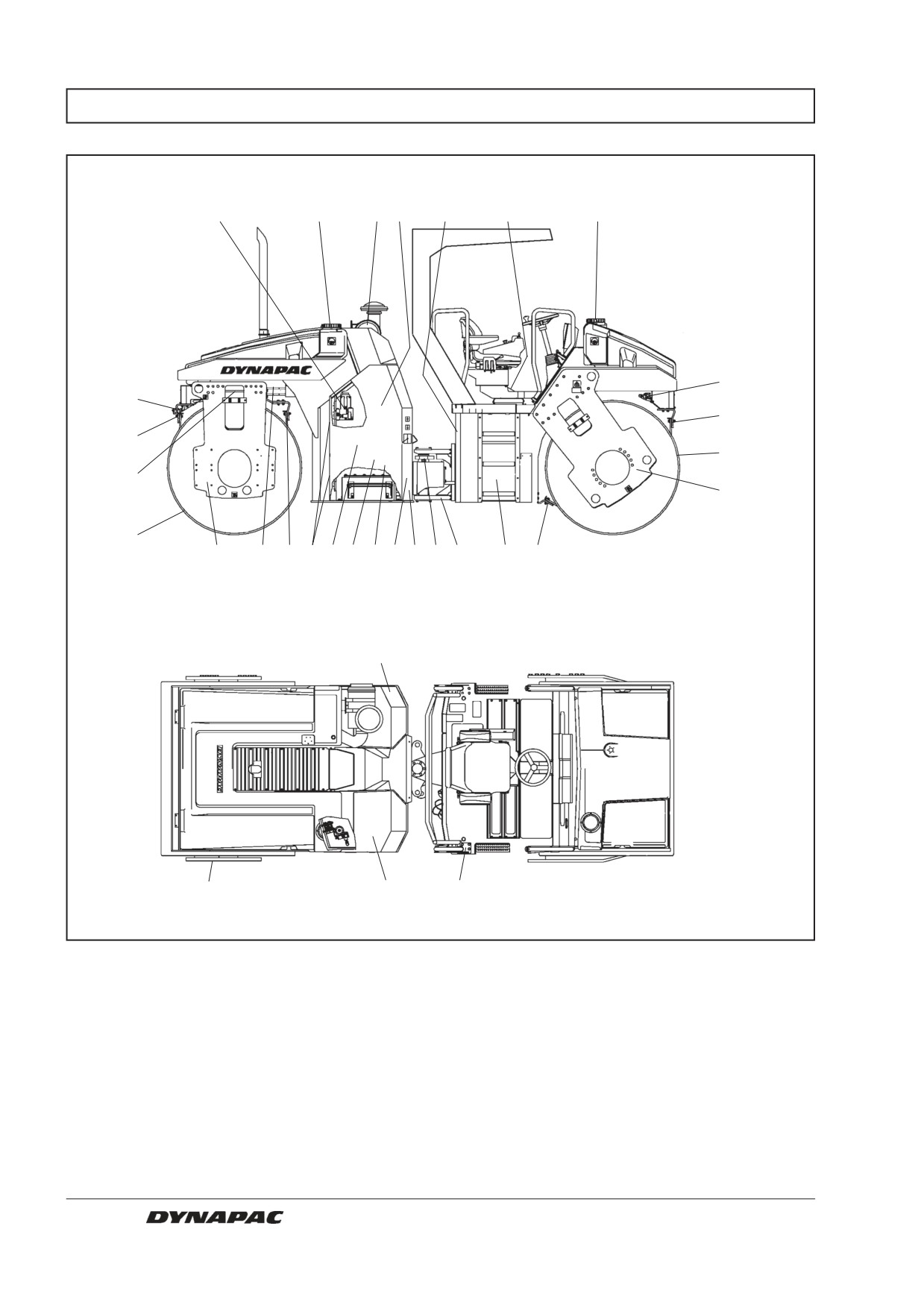
MAINTENANCE SCHEDULE
23
5
1
2
3
4
5
6
6
7
7
8
20
19
8
19
18
7 17 16 15 14 13 12 11 10
9
7
21, 22
23
24
25
Fig. 1 Service and maintenance points
1. Air cleaner
10. Articulated steering
19. Rubber element
2. Engine oil
11. Steering cylinder
20. Pivot bearing
3. Fuel cap
12. Hydraulic fluid filter
21. Battery
4. Seat bearing
13. Hydraulic fluid level
22. Hydraulic fluid cooler/Radiator
5. Water tanks
14. Hydraulic reservoir cap
23. Tire (Combi)
6. Watering system
15. Hydraulic reservoir
24. Pump gearing
7. Scrapers
16. Diesel engine
25. Rail catch
8. Drums
17. Hinge
9. Fuel tank
18. Pivot cylinder
8
CC 422/HF/422C/CHF - CC 432 - CC 522/HF/522C/CHF M422EN5
MAINTENANCE MEASURES
The periodic measures should be performed primarily
after the specified hours of operation. Use the daily,
weekly, etc. time periods only where this is not possible.
Remove all dirt before filling, when checking
oils and fuel, and when lubricating with oil or
grease.
The engine manual specifies additional ser-
vice/maintenance instructions which relate to
the diesel engine.
Every 10 hours of operation (Daily)
Item in
Measure
See page
Comments
fig. 1
Before starting each day
2
Check level of engine oil
11
See engine manual
22
Check level of engine coolant
11
13
Check level in hydraulic reservoir
12
3
Refuel
12
5
Fill the water tanks
12
6
Check the watering system/drum
13
6
Emergency watering
14
7
Check setting of scrapers/drum
14
Inspect spring-action scrapers
14
23
Check the watering system/tyres
15
23
Check setting of scrapers/tyres
15
Check brakes
16
Every 50 hours of operation (Weekly)
Item in
Measure
See page
Comments
fig. 1
10
Lubricate the steering articulation
17
11
Lubricate steering cylinder mounts
17
18
Lubricate control cylinder for pivot steering
17
Optional
1
Inspect and if necessary clean the filter
element in the air cleaner
18
Replace as required
23
Check the tire pressure (Combi)
19
24
Check oil level in pump gearing
19
Inspect the air conditioning
20
Optional
Inspect/lubricate the edge cutter
20
Optional
After the first 50 hours of operation change only the drum oil and all the oil filters.
CC 422/HF/422C/CHF - CC 432 - CC 522/HF/522C/CHF M422EN5
9
MAINTENANCE MEASURES
Every 250 hours of operation (Monthly)
Item in
Measure
See page
Comments
fig. 1
22
Clean the hydraulic cooler and the
water radiator
21
Or when required
21
Check level of battery fluid
21
Inspect the air conditioning
23
Optional
Every 500 hours of operation (Every three months)
Item in
Measure
See page
Comments
fig. 1
16
Change engine fuel filter
See engine manual
2
Change the engine oil and oil filter
22, 23
See engine manual
8
Check oil level in drums
24
20
Lubricate the pivot bearing
25
Optional
19
Check the rubber elements and bolted joints
25
14
Check the cap/vent of the hydraulic reservoir
25
17
Lubricate hinges and controls
26
4
Lubricate the seat bearing
26
Grease the steering chain
27
16
Change/clean the engine prefilter
27
Every 1000 hours of operation (Every six months)
Item in
Measure
See page
Comments
fig. 1
16
Check engine valve clearance
See engine manual
16
Check the engine belt-drive system
See engine manual
12
Change hydraulic filter
28
1
Change main filter of the air cleaner
28
24
Change oil in the pump gearing
29
Replace air cleaner filter in cab
29
8
Change oil in drum/drums (HF version)
29
Every 2000 hours of operation (Yearly)
Item in
Measure
See page
Comments
fig. 1
15
Change fluid in hydraulic reservoir
30
8
Change oil in drum/drums
30
9
Empty and clean the fuel tank
30
5
Empty and clean the water tanks
31
Lubricate the Forward/Reverse control
31
10
Check the condition of the articulation
32
Overhaul air conditioning
33
Optional
Overhaul compressor
34
Optional
Overhaul drying filter
34
Optional
10
CC 422/HF/422C/CHF - CC 432 - CC 522/HF/522C/CHF M422EN5
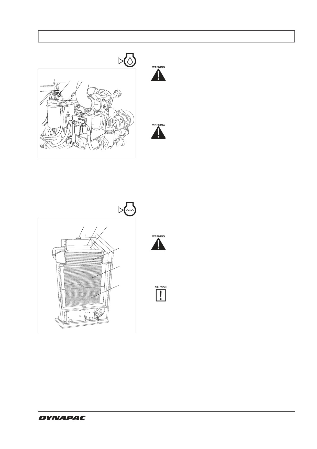
EVERY 10 HOURS OF OPERATION (Daily)
Diesel engine,
oil level - Check
Place the roller on a level surface. Switch
1
2
the engine off and push in the reserve/
parking brake knob for all checking and
adjustments on the roller, unless otherwise
specified.
The oil dipstick is accessible through the right door of
the engine compartment.
Beware of hot parts of the engine and ex-
haust pipe when taking out the oil dipstick.
Observe caution. Wear gloves and safety
goggles.
Fig. 2
Engine compartment
The dipstick is located on the short side of the engine
1. Oil dipstick
above the hydraulic pumps.
2. Filler cap
Pull up the dipstick (1) and ensure that the oil level is
between the upper and lower mark. For further details,
see the engine manual.
Coolant level - Check
Check that level of the coolant is between the max. and
1
2
3
min. marks.
Observe caution if the filler cap must be
4
opened while the engine is hot. Wear glo-
ves and safety goggles.
5
Fill with a mixture of 50% water and 50% anti freeze.
See page 3 in these instructions and in the engine
manual.
6
Flush the system every other year and
change the coolant. Ensure also that air can
flow unrestricted through the radiator.
Fig. 3
Radiator
1. Filler cap
2. Level/max. mark
3. Level/min. mark
4. Intercooler
5. Radiator
6. Hydraulic fluid cooler
CC 422/HF/422C/CHF - CC 432 - CC 522/HF/522C/CHF M422EN5
11
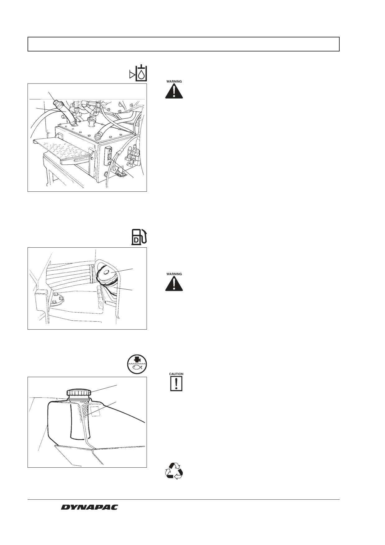
EVERY 10 HOURS OF OPERATION (Daily)
Hydraulic reservoir,
level check - Filling
Place the roller on a level surface. Switch
3
the engine off and push in the reserve/
parking brake knob for all checking and
2
adjustments on the roller, unless otherwise
specified.
Open the right door of the engine compartment.
Make sure that the oil level is between the max/min
marks. Top off with hydraulic fluid according to the
lubricant specification if the level is too low.
1
Fig. 4
Hydraulic reservoir
1. Oil sight glass
2. Filler hose
3. Filler cap
Fuel tank - Refueling
Refuel every day before starting to work. Screw off the
lockable tank cap (1) and fill diesel fuel to the lower
1
edge of the filler pipe (2).
Never refuel while the engine is running,
2
do not smoke, and avoid spilling fuel.
See the engine handbook for the grade of diesel fuel.
The tank holds 200 litres (52.8 gal) of fuel.
Fig. 5
Fuel tank
1. Tank cap
2. Filler pipe
Water tanks - Filling
Screw off the tank cap (1) and fill with pure
1
water. Do not remove the strainer (2).
2
Fill both water tanks; they hold 485 liters (128 gal)
each.
A step is located on the hydraulic reservoir behind the
right door of the engine compartment to facilitate ac-
cess to the tank cap, and also a retractable step on the
right front drum fork.
Sole additive: A small amount of environment
Fig. 6
Rear water tank
friendly antifreeze, and for combi-models
1. Tank cap
possibly cutting fluid.
2. Strainer
12
CC 422/HF/422C/CHF - CC 432 - CC 522/HF/522C/CHF M422EN5
EVERY 10 HOURS OF OPERATION (Daily)
Sprinkler system/Drum
- Checking/Cleaning
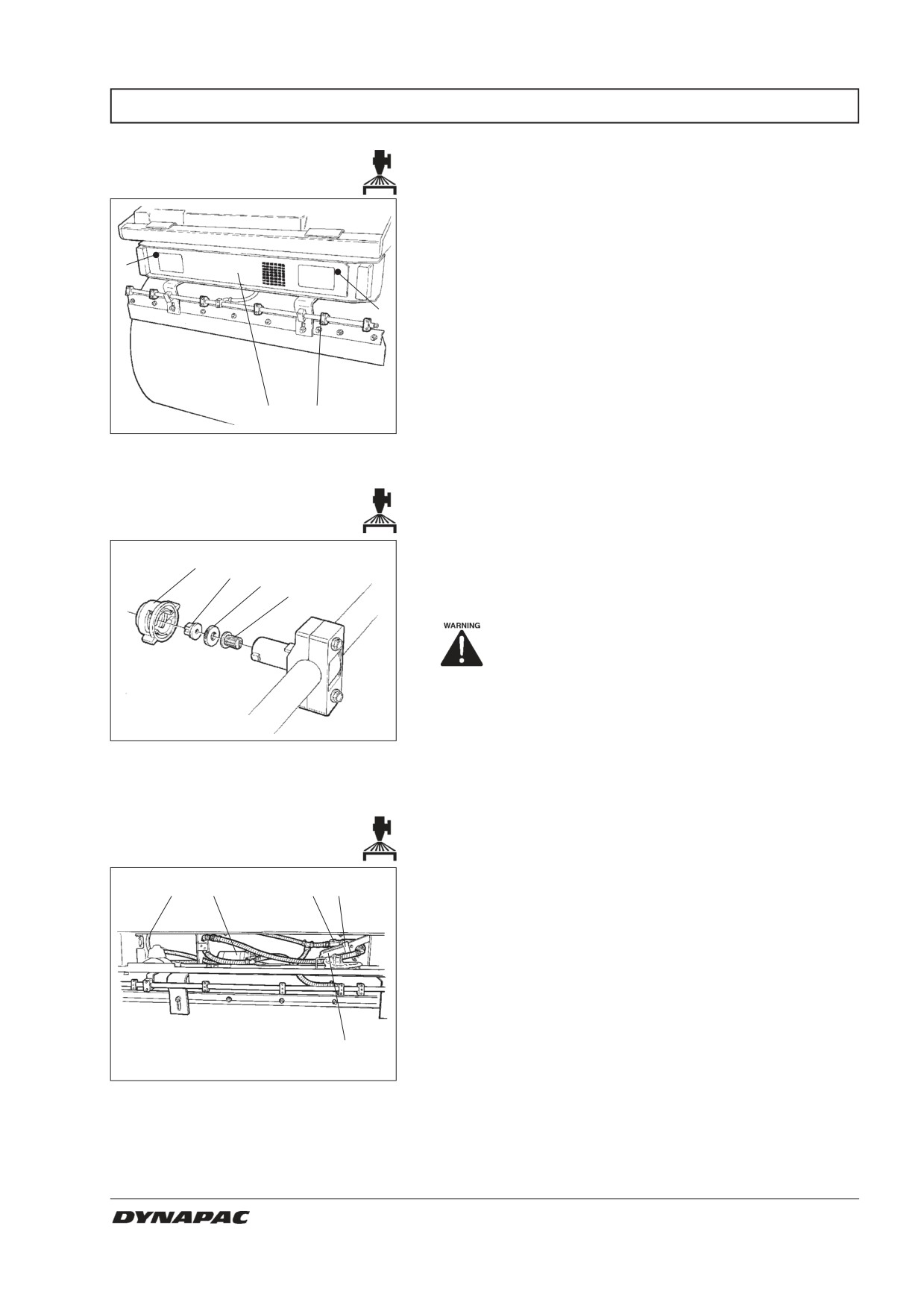
Start the sprinkler system and make sure that no
nozzle (1) is clogged. If necessary, clean clogged
nozzles and the coarse filter located adjacent to the
water pump (2); see figures below.
3
A pump system is located underneath each water tank
3
behind the cover (2), which is opened by turning the
quick-screws (3) a 1/4 turn counter-clockwise. To lock
the cover, place the screws with the slot vertical and
push straight in.
2
1
Fig. 7
Rear drum
1. Nozzle
2. Pump system/cover
3. Quick-screws
Dismantle the clogged nozzle by hand. Blow the nozzle
2
(2) and fine filter (4) clean with compressed air, or
3
4
install replacement parts and clean the clogged parts at
a later opportunity.
Use protective goggles when working with
compressed air.
Fig. 8
Nozzle
1. Sleeve
2. Nozzle
3. Seal
4. Fine filter
When cleaning the coarse filter (1), close the stopcock
5
4
2
1
(2) and loosen the filter housing (3).
Clean the filter and filter housing, ensure that the rubber
gasket in the filter housing is intact.
After inspection and any cleaning, start the system and
check that it works.
A drain cock (5) is located in the left part of the pump
3
system area. This facilitates draining of both tank and
pump system.
Fig. 9
Pump system
1. Coarse filter
2. Stop cock
3. Filter housing
4. Water pump
5. Drain cock
CC 422/HF/422C/CHF - CC 432 - CC 522/HF/522C/CHF M422EN5
13
EVERY 10 HOURS OF OPERATION (Daily)
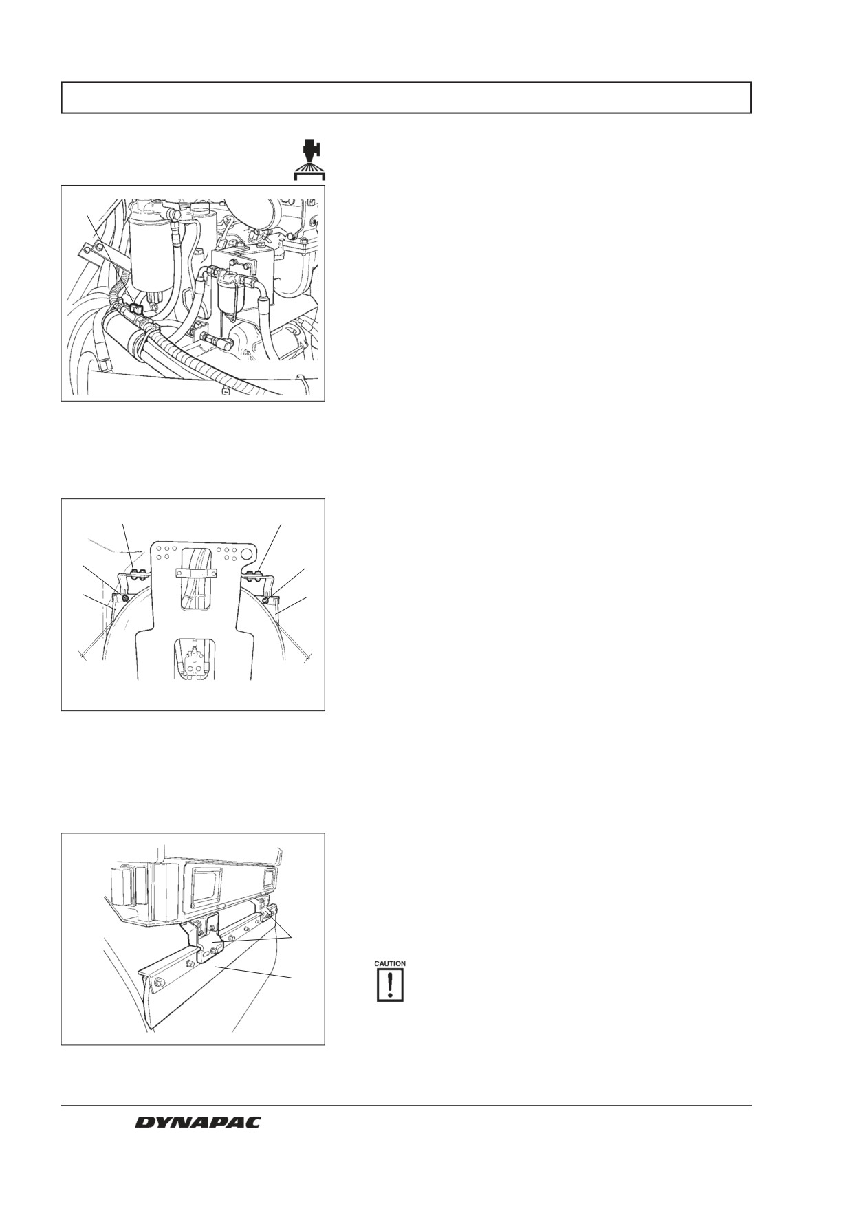
Emergency watering
If one of the water pumps stops, the remaining pump
1
will be able to keep the sprinkler system operating -
however, at reduced capacity.
To operate with only one pump, open the stopcock (1)
in the water hose in the engine compartment, and also
the stopcock on the coarse filter by the pump that has
stopped, see pump system.
Fig. 10
Engine compartment, right side
1. Stopcock
Scrapers, fixed
- Checking/Setting
Make sure that the scrapers are undamaged. Adjust the
3
3
scrapers so that they lie 1-2 mm (0.04-0.08 in) from the
drum. For special asphalt compounds, it may be better if
2
the scraper blades (1) lie lightly against the drums.
2
1
Asphalt remnants can accumulate on the scraper and
1
affect the contact force.
Loosen the screws (2) to adjust the scraper blade up or
down.
1-2 mm
1-2 mm
Loosen the screws (3) to adjust the contact pressure of
the scraper blade against the drum.
Fig. 11
Rear drum scrapers
1. Scraper blade
Remember to tighten all the screws after any
2. Adjusting screws
adjustment.
3. Adjusting screws
Scrapers, spring loaded
(Optional) - Checking
Make sure that the scrapers are undamaged. The
spring loaded scrapers require no adjustment because
the spring force provides the correct contact force.
Asphalt remnants can accumulate on the scraper and
affect the contact force.
1
Clean as needed.
2
The scrapers must be retracted from the drum
during transport driving.
Fig. 12
Spring loaded scrapers
1. Spring mechanism
2. Scraper blade
14
CC 422/HF/422C/CHF - CC 432 - CC 522/HF/522C/CHF M422EN5
EVERY 10 HOURS OF OPERATION (Daily)
Sprinkler system/Wheels
- Checking/Cleaning
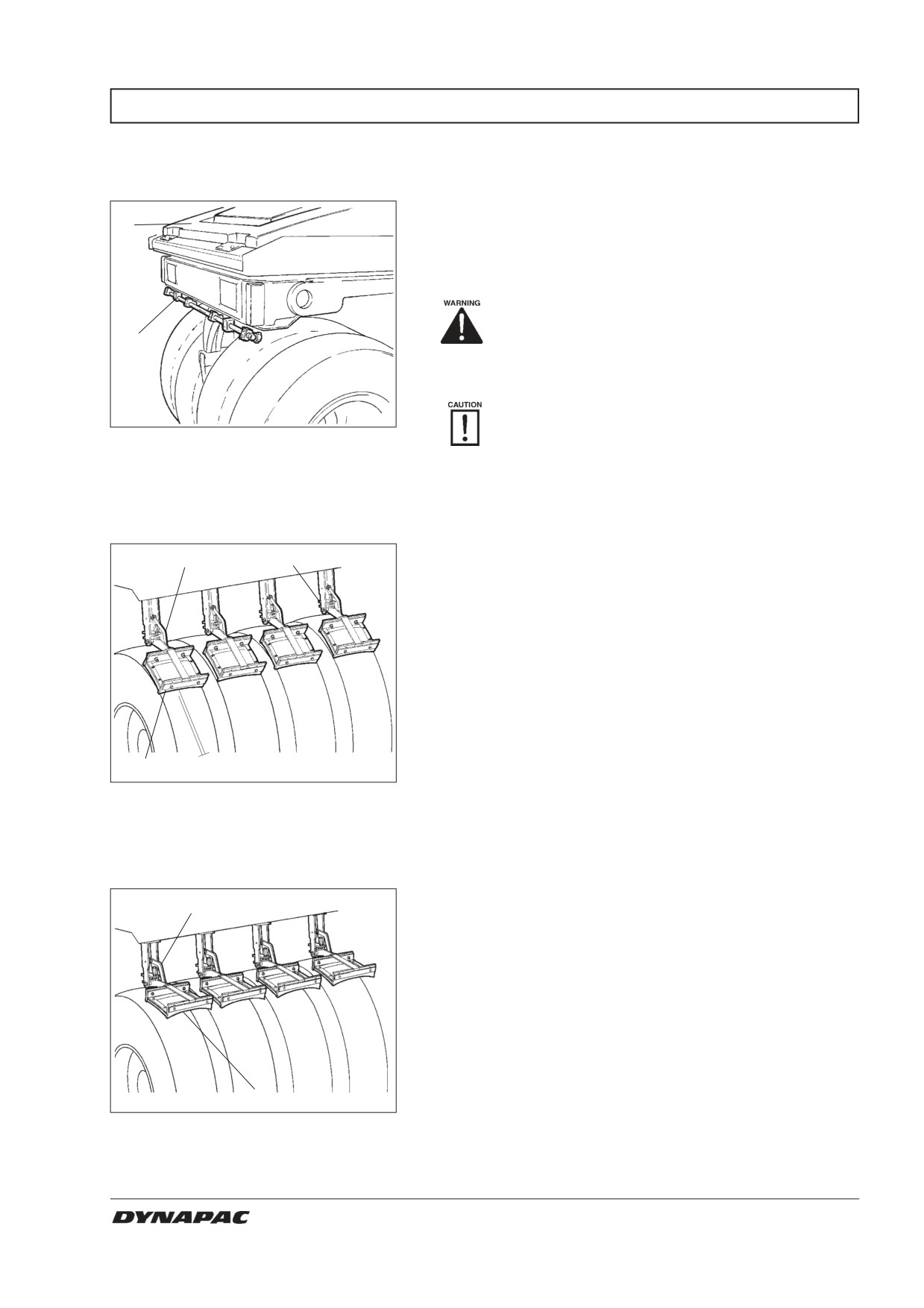
Fill the rear tank with emulsion fluid; for example, water
1
mixed with 2% cutting fluid. Make sure that the sprink-
ler nozzles (2) are not clogged. Clean them and the
filter if necessary. See under Sprinkler system/Drum -
Check/Cleaning, for detailed instructions.
Fluids that are flammable or detrimental to
2
the environment may not be used in the
emulsion tank.
Inspect the tire tread now and then to detect
asphalt compound that has fastened. This is
Fig. 13
Wheel rack
likely until the tires are sufficiently warm.
1. Rear water tank
2. Sprinkler nozzle
Scrapers
- Checking/Setting
Make sure that the scrapers are undamaged. Adjust
2
3
the scrapers so that they lie 1-2 mm (0.04-0.08 in) from
the tires. For special asphalt compounds, it may be
better if the scraper blades (1) lie lightly against the
tires. Contact is adjusted with the screw at the back of
the scraper mount.
1
1-2 mm
Fig. 14
Tire scrapers
1. Scraper blade
2. Locking bracket
3. Adjusting screw
The scrapers shall hang freely away from the tyres
2
during transport driving. Lift up the scraper blades (1)
and latch them in the raised position with locking
bracket (2).
1
Fig. 15
Tire scrapers
1. Scraper blade
2. Locking bracket
CC 422/HF/422C/CHF - CC 432 - CC 522/HF/522C/CHF M422EN5
15
EVERY 10 HOURS OF OPERATION (Daily)
Brake function
- Check
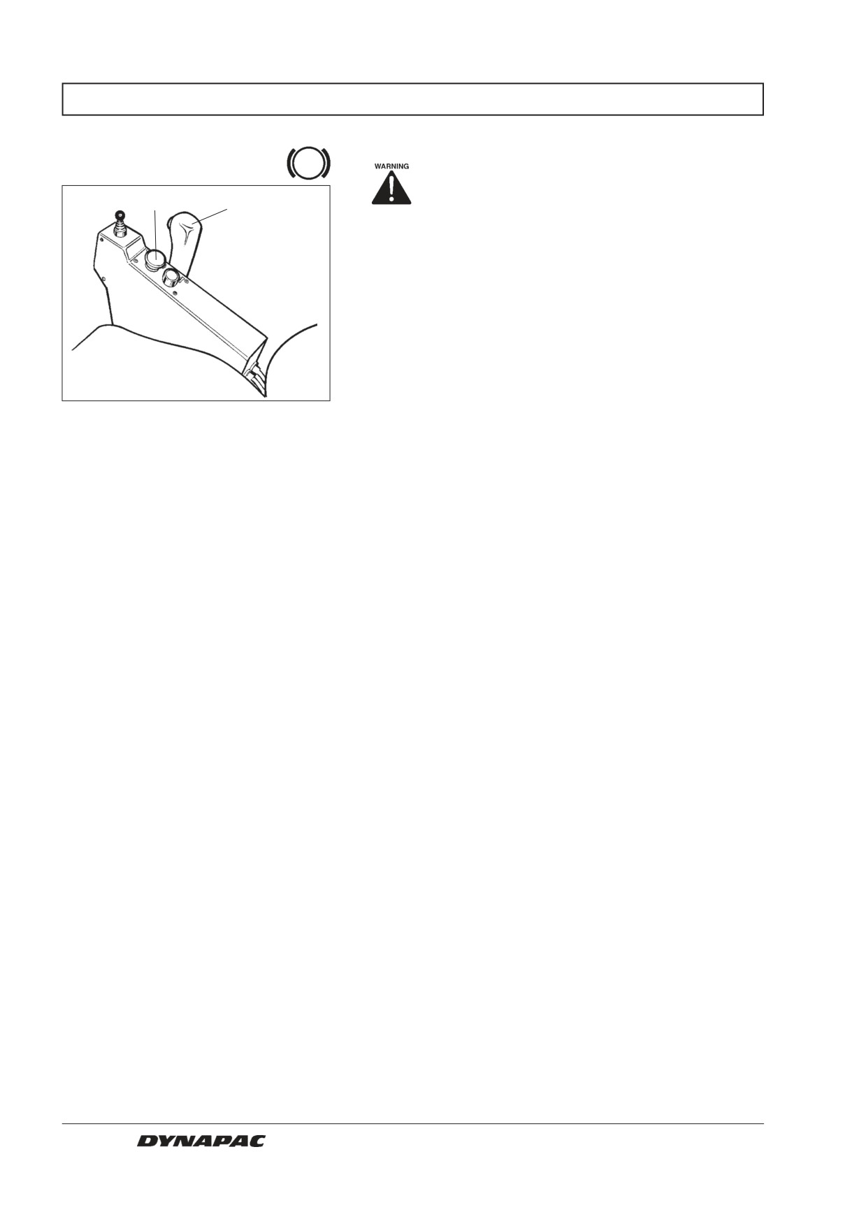
Check operation of the brakes as follows:
38
40
Drive the roller slowly forward.
Push the reserve/parking brake knob (38); the warning
lamp on the instrument panel should light and the roller
should stop.
After testing the brakes, set the forward/reverse lever
(40) in neutral.
Pull up the reserve/parking brake knob.
Fig. 16
Control panel
38. Reserve/parking brake knob
The roller is now ready for operation.
40. Forward/reverse lever
16
CC 422/HF/422C/CHF - CC 432 - CC 522/HF/522C/CHF M422EN5
EVERY 50 HOURS OF OPERATION (Weekly)
Steering joint
- Lubrication
Place the roller on a level surface. Switch the
1
engine off and push in the reserve/parking-
brake knob for all checking and adjustments
on the roller, unless otherwise specified.
Allow no one to get near the steering joint
when the engine is running. Danger of
being crushed when steering is operated.
Push the reserve/parking brake knob before
lubricating.
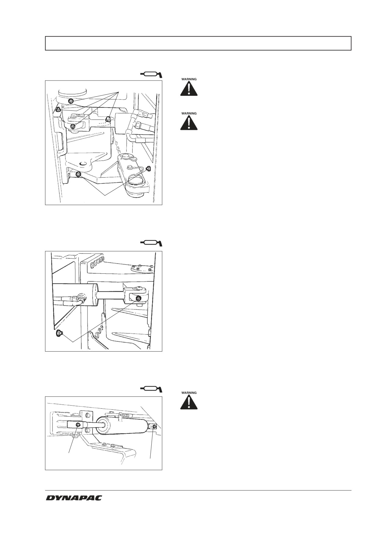
Turn the steering wheel fully to the left to gain access
to all four grease nipples (1) from the right side of the
machine.
Wipe the grease nipples (1). Grease each nipple with
1
five strokes of the hand-operated grease gun. Make
Fig. 17
Right side of articulation
sure that grease penetrates the bearings. If grease
1. Grease nipples
does not penetrate the bearings, it may be necessary
to relieve the articulation joint with a jack while repea-
Steering cylinder
ting the greasing process.
- Lubrication
Turn the machine back for driving straight ahead. This
makes the two grease nipples of the steering cylinder
accessible from the left side of the machine.
Wipe the nipples (1) and grease each one with three
strokes of the hand-operated grease gun.
1
Fig. 18
Left side of articulation
1. Grease nipples
Pivot cylinder
- Lubrication (Optional)
Allow no one near the rear drum while the
engine is running. Danger of being crus-
hed when the drum is operated.
Turn the rear drum for turning left to make the two
grease nipples (1) accessible from the right side of the
machine.
1
Wipe the nipples and lubricate in the same way as for
1
the steering cylinder above.
Fig. 19
Pivot cylinder
1. Grease nipples
CC 422/HF/422C/CHF - CC 432 - CC 522/HF/522C/CHF M422EN5
17
EVERY 50 HOURS OF OPERATION (Weekly)
Air cleaner
- Check/Cleaning
Replace or clean the main filter of the air
2
3
cleaner when the warning lamp on the instru-
ment panel lights at full engine revs.
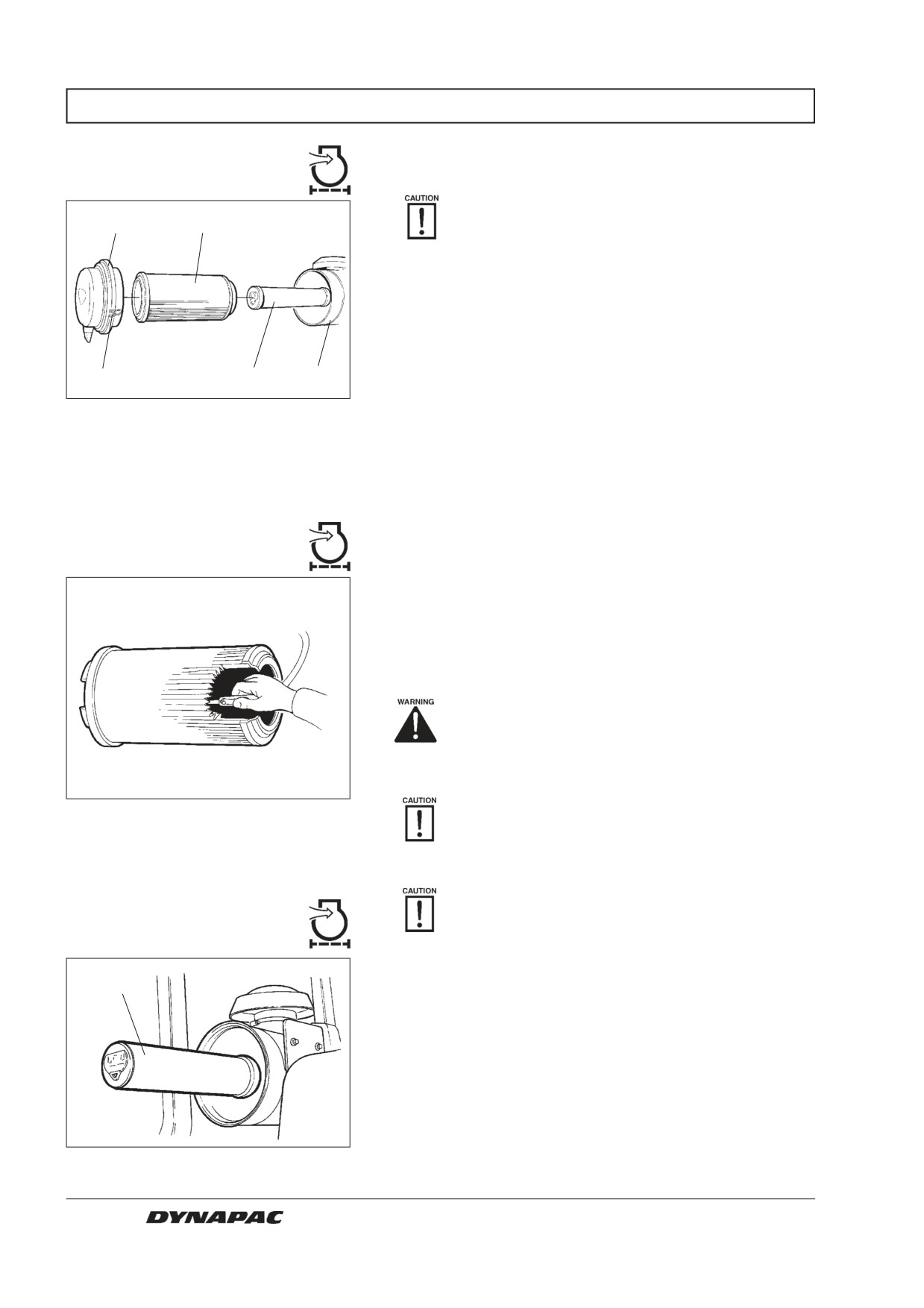
Release the three locking braces (1) and pull off the
cover (2), pull out the main filter (3).
Do not remove the backup filter (4).
1
4
5
Fig. 20
Air cleaner
1. Locking braces
2. Cover
3. Main filter
4. Backup filter
5. Filter housing
Main filter - Cleaning with
compressed air
Use compressed air at a maximum pressure of 5 bar
(72 psi) to clean the main filter by blowing up and down
along the inside of the pleated paper filter.
Hold the air nozzle at least 2 to 3 cm (0.8-1.2 in) from
the paper pleats so as not to tear the paper.
Use protective goggles when working with
compressed air.
Wipe the inside of the cover (2) and the filter housing (5).
Fig. 21
Main filter
Ensure that the hose clips between the filter
housing and the intake hose are tightened and
that the hoses are intact. Inspect the entire
hose system all the way to the engine.
Change the main filter after cleaning it five
Backup filter
times.
– Replacement
Replace the backup filter with a new one after cleaning
4
or changing the main filter five times. The backup filter
cannot be cleaned and reused.
To change the backup filter (4), pull the old filter out
from its holder, insert a new one and reassemble the air
cleaner in the reverse order.
Fig. 22
Air filter
4. Backup filter
18
CC 422/HF/422C/CHF - CC 432 - CC 522/HF/522C/CHF M422EN5
EVERY 50 HOURS OF OPERATION (Weekly)
Tires
- Tire pressure
Check the tire pressure with a pressure gauge.
Make sure that the tires have equal pressure.
Recommended pressure: See Technical
Specifications.
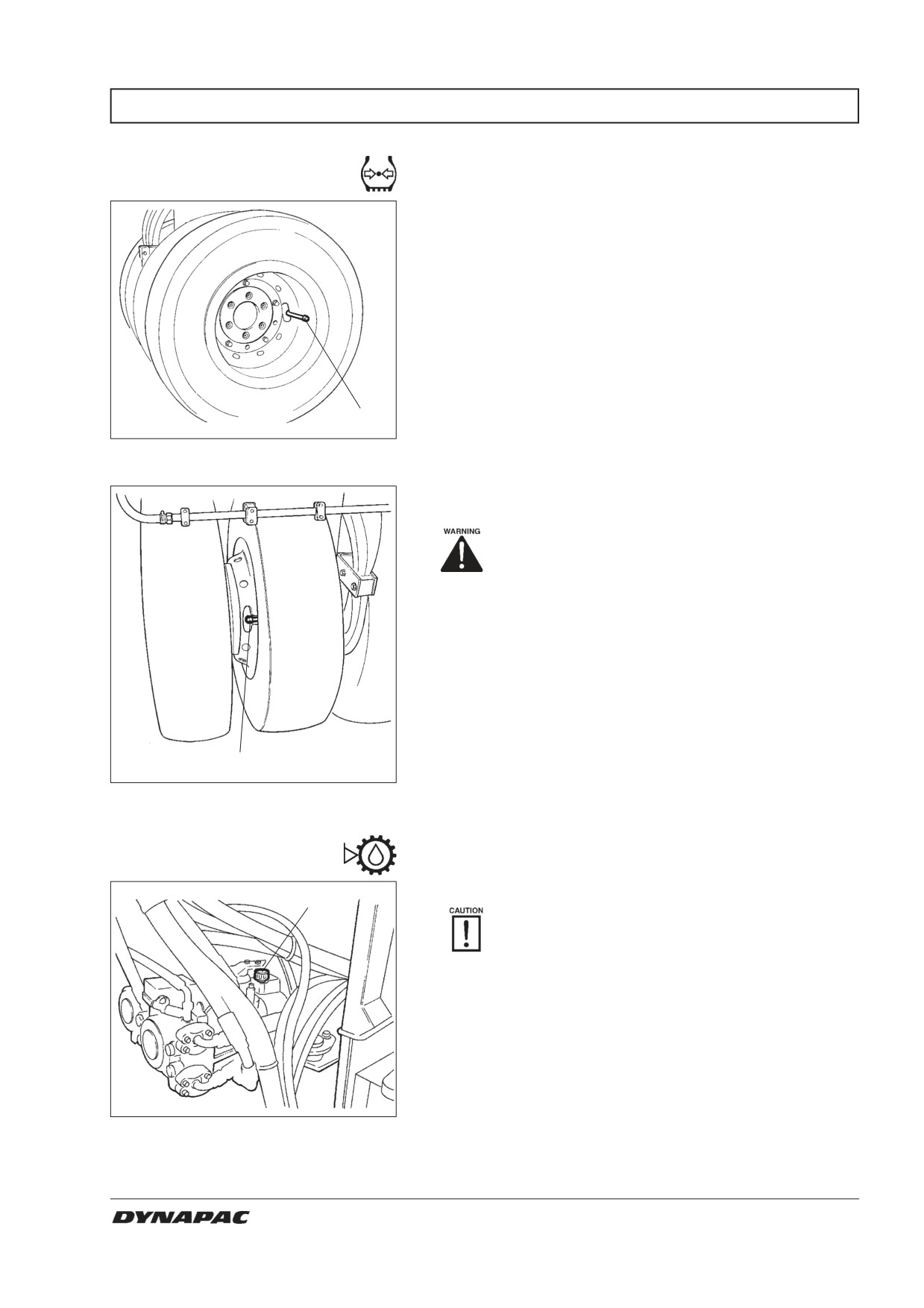
The figure shows the position of the air valve on the
outer tires.
1
Fig. 23
Outer wheel
1. Air valve
The figure shows the position of the air valve on the
inner tires.
Check the safety manual that accompanies
the roller before filling the tires with air.
1
Fig. 24
Inner wheel
1. Air valve
Pump drive, oil level
- Checking/Topping up
Position the roller on a flat surface.
1
When checking the oil level, the engine must
be switched OFF and the parking brake
applied.
Open the right door of the engine compartment and
screw off the dipstick (1).
The oil level must be between the two marks at the
bottom of the dipstick.
Fill with transmission oil if required; see lubricant
specification.
Fig. 25
Pump gearing
Ensure that the rubber packing between the dipstick
1. Dipstick
and gear housing is in place, and firmly screw in the
dipstick.
CC 422/HF/422C/CHF - CC 432 - CC 522/HF/522C/CHF M422EN5
19
EVERY 50 HOURS OF OPERATION (Weekly)
Air conditioning
- Inspection (Optional)
Never work under the roller with the engi-
ne running. Park on a level surface, chock
the wheels and press the parking brake
control.
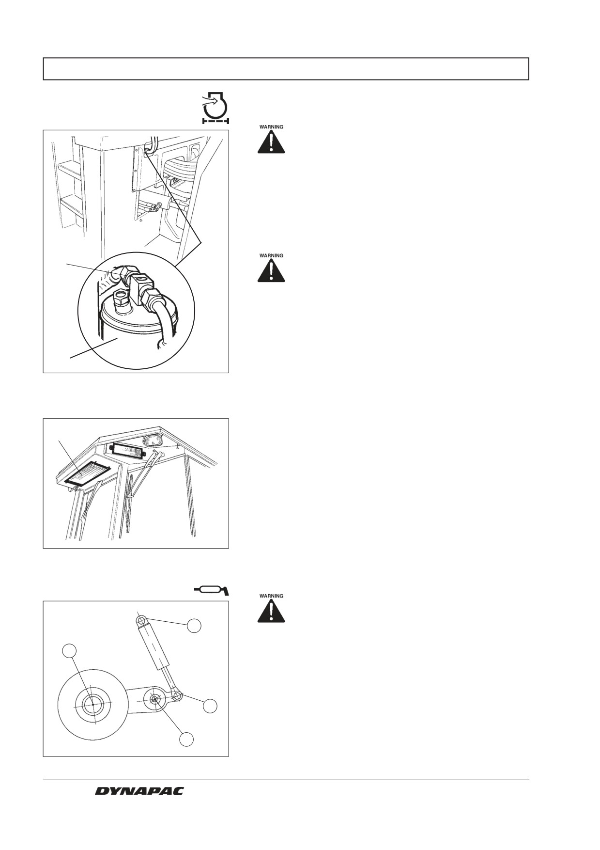
When the unit is in operation, check in the sight glass
(1) that no bubbles are visible in the dryer filter.
Steer the roller fully to the right for easier access to the
dryer filter.
1
Always push the parking brake knob.
The filter is located on the left side underneath the cab.
If bubbles are visible in the sight glass it is a sign that
the level of refrigerant is too low. The sight glass is
visible where the hoses go in under the cab floor, see
figure. If so, stop the unit. There is a risk of damage to
the unit if it is run with insufficient level of refrigerant. Fill
2
with refrigerant.
Fig. 26
Drying filter
1. Sight glass
2. Filter housing
In the event of noticeable deterioration of cooling capa-
1
city, clean the condenser element (1), which is located
at the rear of the cab roof. Also clean the cooling unit
inside the cab.
Fig. 27
Cab
1. Condenser element
Edge cutter - Lubrication
See the Operation manual for how to ope-
rate the edge cutter.
2
Grease the four points indicated in the figure.
1
Additional lubrication should also be with grease, see
Lubricant specifications.
Grease all bearing points with five strokes of a
3
handoperated grease gun.
4
Fig. 28
Four lubrication points
20
CC 422/HF/422C/CHF - CC 432 - CC 522/HF/522C/CHF M422EN5
EVERY 250 HOURS OF OPERATION (Monthly)
Hydraulic fluid cooler
- Check/Cleaning
Place the roller on a level surface. Switch
the engine off and push in the reserve/parking-
1
brake knob for all checking and adjustments
on the roller, unless otherwise specified.
Open the left-hand door to the engine compartment to
2
gain access to the radiator and the hydraulic fluid
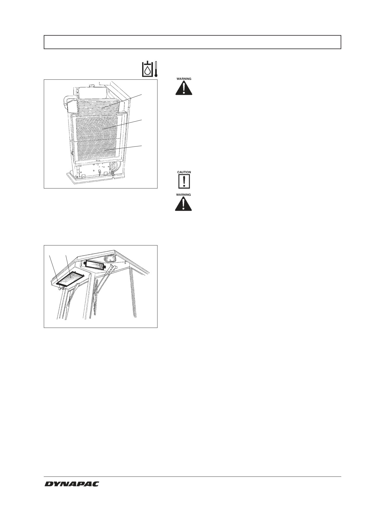
cooler.
Ensure that air can flow unrestricted through the cooler
and radiator, (1), (2) and (3).
3
Blow a dirty cooler and radiator clean with compressed
air, or wash using a high-pressure washing jet.
Take care when using a high-pressure
washing jet, do not hold the nozzle too close to
the cooler.
Fig. 29
Radiator
1. Intercooler
Use protective goggles when working with
2. Radiator
compressed air.
3. Hydraulic fluid cooler
Air conditioning
- Inspection (Optional)
Inspect refrigerant hoses and connections and make
1
2
sure that there are no signs of oil film that could indicate
leakage of refrigerant.
Fig. 30
Air conditioning
1. Refrigerant hoses
2. Condenser element
CC 422/HF/422C/CHF - CC 432 - CC 522/HF/522C/CHF M422EN5
21
EVERY 250 HOURS OF OPERATION (Monthly)
Battery - Checking the
electrolyte level
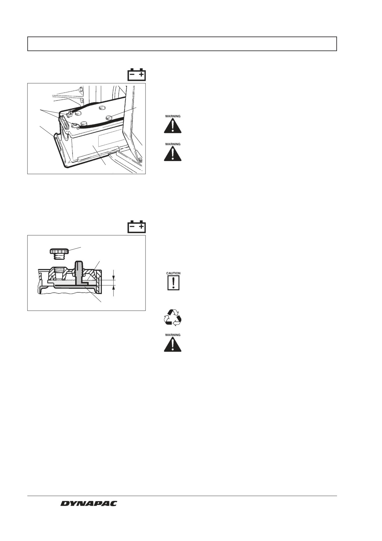
Open the left door of the engine compartment.
Pull out the battery that is located on the floor behind
2
the coolers.
3
Use safety goggles. The battery contains
4
acid. Rinse with water if electrolyte comes
into contact with the body.
Never use an open flame when checking
the electrolyte level. Explosive gas is genera-
ted when the alternator is charging.
1
Take off the cell caps and make sure that electrolyte is
Fig. 31
Battery space
about 10 mm (0.4 in) above the plates. Check the level
1. Battery
of all cells. Top off with distilled water to the right level if
2. Cell cap
the level is low. The engine should be run for a while
3. Cable shoes
before topping off with distilled water if the ambient
4. Pull-out handle
temperature is below freezing. Otherwise, the electrolyte
might freeze.
Battery cell
Make sure that ventilation holes in the cell cover are
not clogged. Then put the cover back on.
1
The cable shoes should be clean and well tightened.
2
Clean corroded cable shoes and grease them with
acid-free Vaseline.
When disconnecting the battery, always
10 mm
disconnect the negative cable first. When
connecting the battery, always connect the
positive cable first.
3
Discard used batteries properly. Batteries
Fig. 32
Electrolyte level in battery
contain lead, which is detrimental to the
1. Cell cap
environment.
2. Electrolyte level
3. Plate
Before doing any electric welding on the
machine, disconnect the battery ground
cable and then all electrical connections to
the alternator.
22
CC 422/HF/422C/CHF - CC 432 - CC 522/HF/522C/CHF M422EN5
EVERY 500 HOURS OF OPERATION (Every three months)
Engine
- Changing the oil
Place the roller on a level surface. Switch
the engine off and push in the reserve/parking-
brake knob for all checking and adjustments
on the roller, unless otherwise specified.
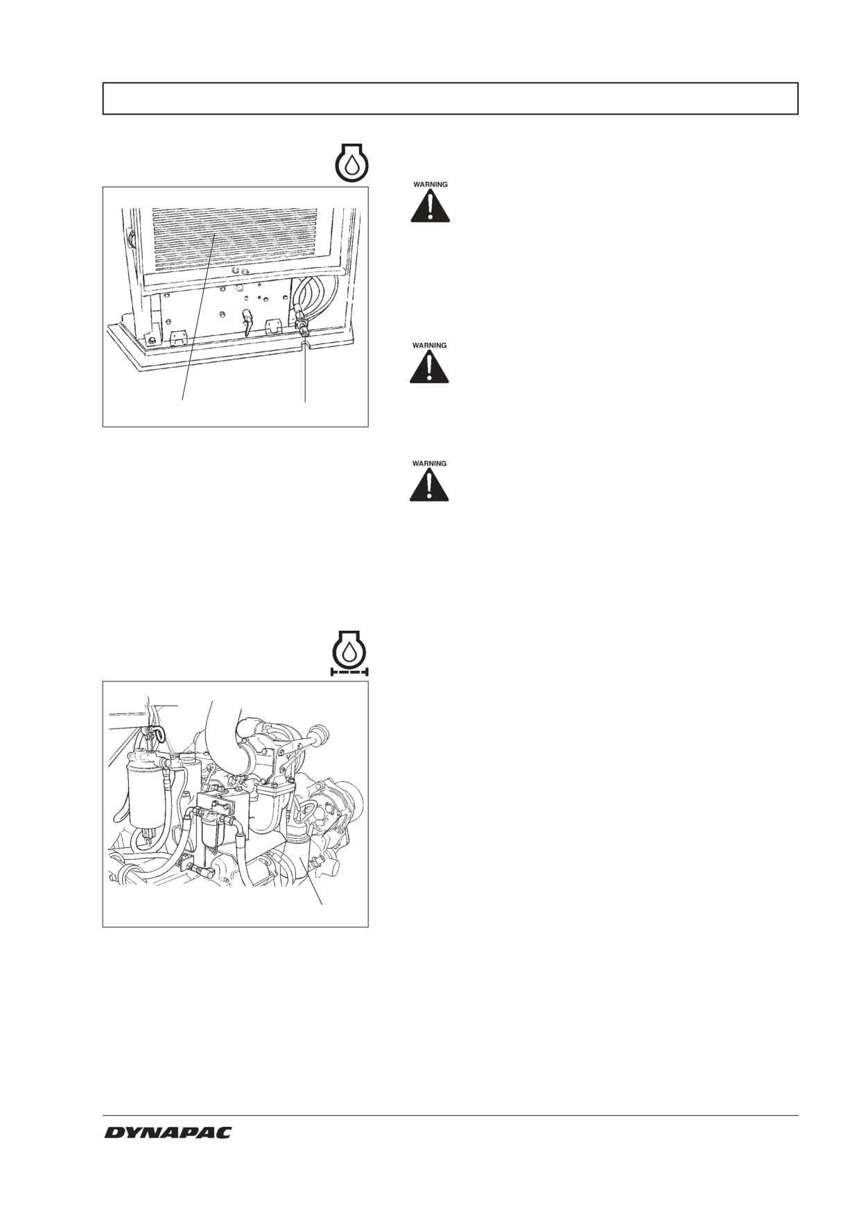
The engine oil drain plug is located adjacent to the
battery behind the left door of the engine compartment.
Run the engine warm before draining the oil.
Ensure that ventilation (evacuation) is
adequate if the engine is run indoors.
(Risk of carbon monoxide poisoning).
2
1
Place a suitable receptacle, for at least 15 litres (4 gal),
Fig. 33
Engine compartment, left side
under the drain plug.
1. Oil drain
2. Radiator
Observe caution when draining the engine
oil. Wear gloves and safety goggles.
Unscrew the oil drain plug (1). Allow all of the oil to
drain off, and refit the plug.
Fill with fresh engine oil; see lubricant specification or
the engine manual for the correct grade of oil.
Check the dipstick to ensure that the engine oil level is
Engine
correct, for details see the engine manual.
– Changing the oil filter
The oil filter (1) can be reached most easily through the
right-hand door of the engine compartment.
See the engine manual for details concerning changing
of the filter.
1
Fig. 34
Engine compartment, right side
1. Oil filter
CC 422/HF/422C/CHF - CC 432 - CC 522/HF/522C/CHF M422EN5
23
EVERY 500 HOURS OF OPERATION (Every three months)
Drum, oil level
- Inspection/Filling
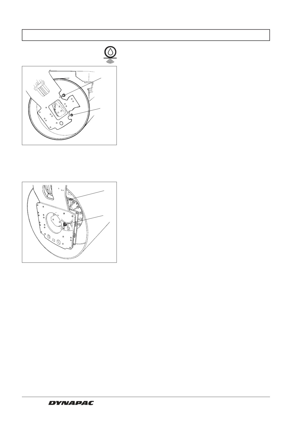
Position the roller with the filler plug (1) - the large plug -
straight up.
1
Wipe clean around the level plug (2) - the small plug -
and unscrew it.
Make sure that the oil level reaches up to the lower
2
edge of the hole, top off with fresh oil as required. See
Lubricant specification.
When removing the filler plug, wipe it clean from any
metal on its magnet.
Make sure that plug seals are intact and replace with
new seals as required.
Fig. 35
Drum, vibration side
Refit the plugs.
1. Filler plug
2. Level plug
Check both drums.
Drive a distance and make sure that the plugs are tight.
CC 432
1
Position the roller with the filler plug (1) straight up.
Wipe clean round the sight glass (2).
2
Ensure that the oil level reaches half way in the sight
glass, top up with fresh oil if the level is not correct.
See Lubricant specification.
When removing the filler plug, wipe it clean from any
metal on its magnet.
Refit the plug.
Fig. 36
Drum, vibration side (CC432)
1. Filler plug
Inspect all four drum halves.
2. Sight glass
Drive a distance and ensure that the plugs are tight.
24
CC 422/HF/422C/CHF - CC 432 - CC 522/HF/522C/CHF M422EN5
EVERY 500 HOURS OF OPERATION (Every three months)
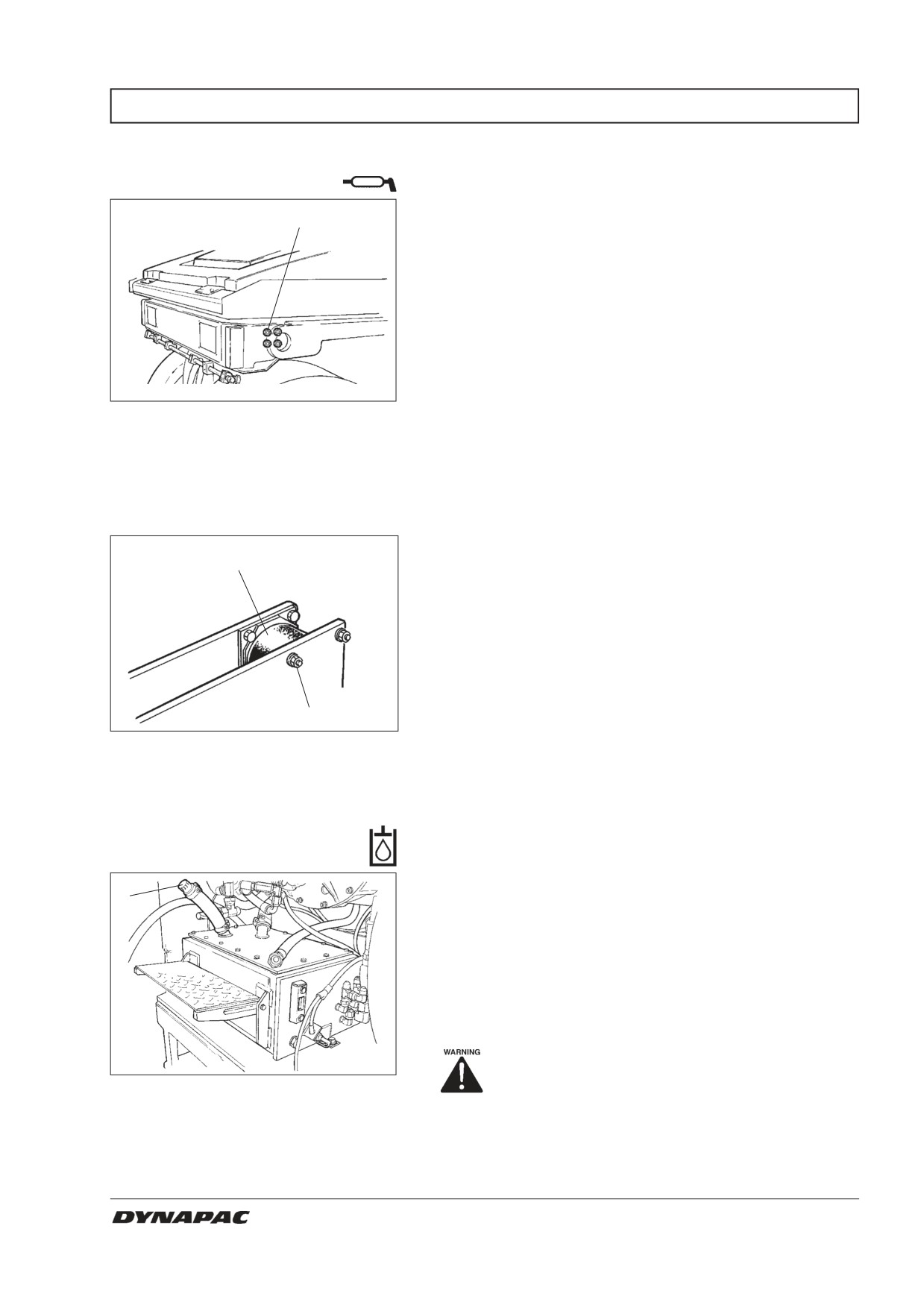
Pivot bearing (Optional)
- Lubrication
Grease each nipple (1) with five strokes of a
1
handoperated grease gun.
Use grease according to the lubricant specification.
Fig. 37
Rear drum, right side
1. Grease nipples, 4 off
Rubber elements and
fastening screws - Check
Check all rubber elements (1), replace all of the
1
elements if more than 25% of them on one side of the
drum are cracked deeper than 10-15 mm (0.4-0.6 in).
Use the blade of a knife or pointed object to assist
when checking.
Make sure that the fastening screws (2) are tightened.
2
Fig. 38
Drum, vibration side
1. Rubber element
2. Fastening screws
Hydraulic reservoir cap
- Check
Open the right door of the engine compartment.
1
Unscrew and make sure that the reservoir cap is not
clogged, air must have unobstructed passage through
the cap in both directions.
If clogged in either direction, clean with a little diesel oil
and blow with compressed air until free passage is
assured or replace the cap with a new one.
Use protective goggles when working with
Fig. 39
Engine compartment, right side
compressed air.
1. Tank cap
CC 422/HF/422C/CHF - CC 432 - CC 522/HF/522C/CHF M422EN5
25
EVERY 500 HOURS OF OPERATION (Every three months)
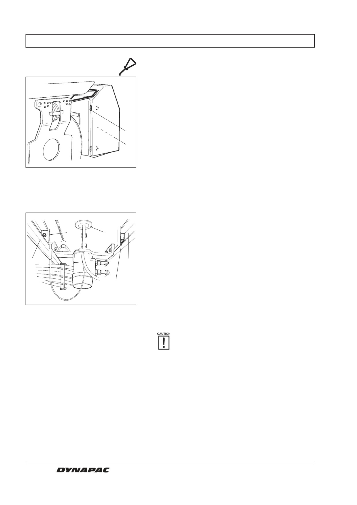
Hinges, controls
- Lubrication
Lubricate both hinges (1) on the engine compartment
doors until grease penetrates through.
Grease the hinges of the cab door in the same way.
Lubricate the hinges of the front and rear spotlight
covers with a few drops of oil.
1
Lubricate the forward/reverse control wires by the
control arm of the hydraulic pump. Apply a few drops of
2
oil to the mouth of the control sleeve.
Fig. 40
Engine hood
1. Hinge
2. Control wires
Seat bearing - Lubrication
Remove both steps from under the operator’s platform,
or one step and cover plate on the other side of the roller
if fitted with a cab.
1
3
Lubricate the seat sliding rails for transverse travel with
five strokes of a hand-operated grease gun. Grease all
four nipples, two of which (1) are accessible from each
2
2
side.
Also grease the slew bearing of the seat with a few
1
strokes of the gun. The lubrication nipple (3) is
accessible after the cover on the seat frame underneath
the front of the seat is removed.
Fig. 41
Seat bearing, underneath
1. Grease nipples
Also lubricate the seat locking mechanism, both for
2. Slide rails
transverse travel and slewing. Use engine oil or drum oil.
3. Lubrication nipple
If the seat begins to bind when resetting, then it
should be lubricated more often than specified
here.
26
CC 422/HF/422C/CHF - CC 432 - CC 522/HF/522C/CHF M422EN5
EVERY 500 HOURS OF OPERATION (Every three months)
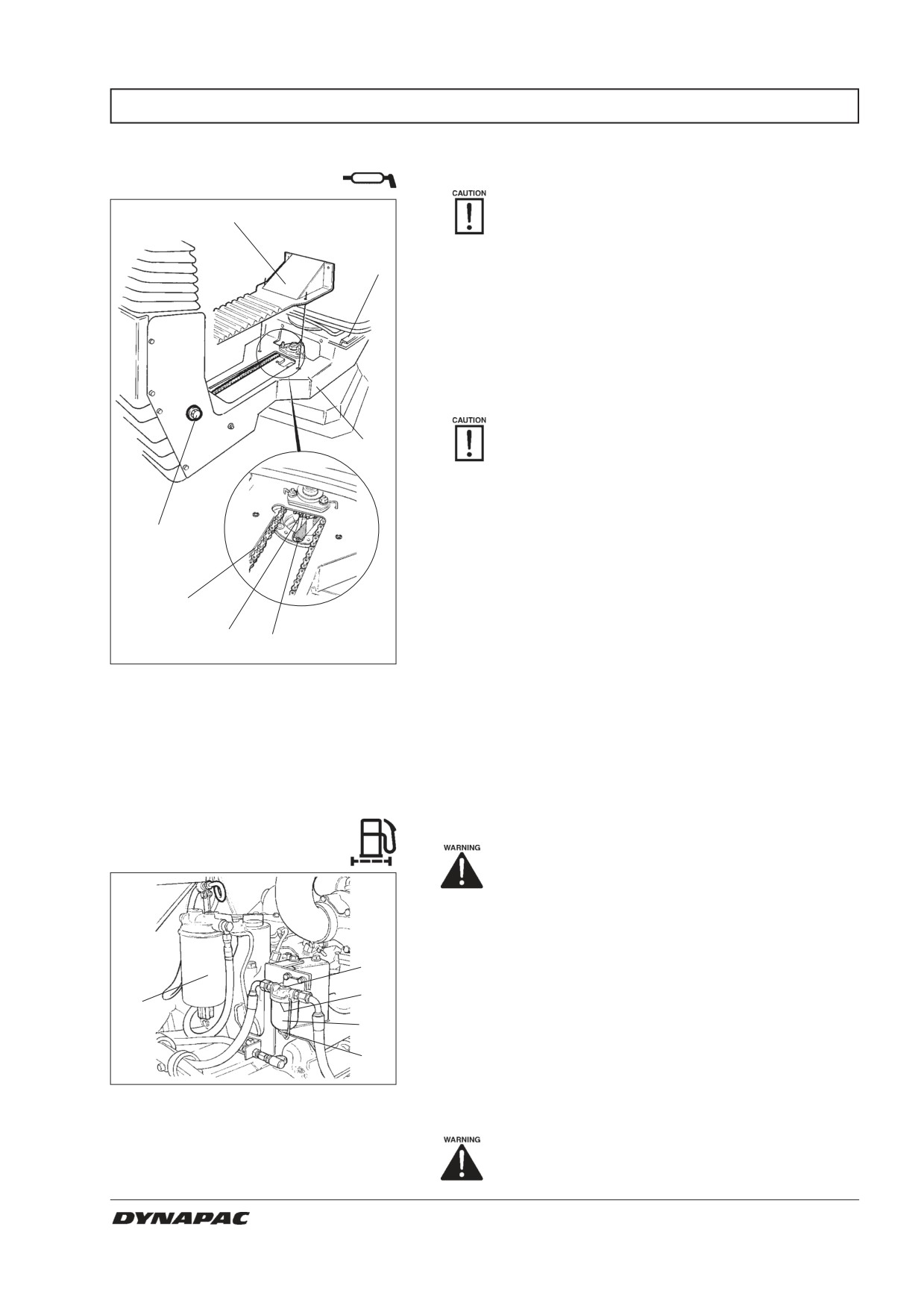
Seat bearing
- Lubrication
Remember that the chain is a vital part of the
5
steering mechanism.
6
Remove the cover (5) to gain access to the lubrication
nipple (1). Lubricate the slew bearing of the operator’s
seat with three strokes of a hand-operated grease gun.
Lubricate the seat locking latch (7), accessible from
below.
Also grease the slide rails of the seat (6).
If the seat begins to bind when resetting, it
7
needs to be lubricated more often.
lean and grease the chain (3) between the seat and
the steering column.
If the chain becomes slack on the cogwheel (2), loosen
4
the screws (4) and move the steering column forward,
tighten the screws and check the tension of the chain.
3
2
1
Fig. 42
Seat bearing
1. Lubrication nipple
2. Cogwheel
3. Steering chain
4. Adjusting screw
5. Cover
6. Slide rails
7. Slew interlock
Diesel engine fuel filter
- Change/cleaning
Place the roller on a level surface. Switch
the engine off and push in the reserve/
parking brake knob for all checking and
adjustments on the roller, unless otherwise
specified.
1
Prefilter, loosen the screw (1) and remove the glass
bowl (2).
3
5
2
Take out the strainer (3) and clean using a non-
flammable fluid. Reinstall the strainer and the bowl.
4
Replace fuel filter. See engine manual.
Fig. 43
Diesel engine
1. Prefilter
Start the engine and check that the pre-filter does not leak.
2. Glass bowl
Make sure there is adequate ventilation
3. Strainer
4. Nut
(extraction) if the diesel engine is run in-
5. Fuel filter
doors. Risk of carbon monoxide poisoning.
CC 422/HF/422C/CHF - CC 432 - CC 522/HF/522C/CHF M422EN5
27
EVERY 1000 HOURS OF OPERATION (Every six months)
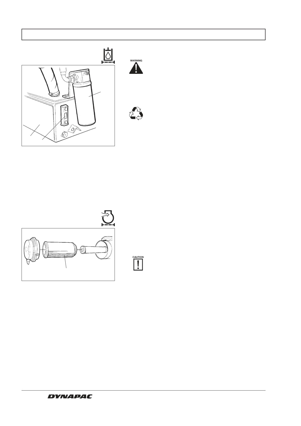
Hydraulic fluid filter
- Changing
Place the roller on a level surface. Switch the
engine off and push in the reserve/parking-
brake knob for all checking and adjustments
on the roller, unless otherwise specified.
1
Open the right door of the engine compartment.
Remove the oil filter (1) and discard it in a safe
manner, it is of the expendable type and
cannot be cleaned.
Thoroughly clean the sealing surface of the filter holder.
2
3
Apply a thin coat of fresh hydraulic fluid on the rubber
Fig. 44
Hydraulic reservoir
gasket of the new filter.
1. Hydraulic filter
2. Reservoir
Screw on the filter by hand, first until the filter gasket
3. Sight glass
makes contact with the filter base and then a further ½
turn.
Start the engine and check that the filter does not leak.
Check level of the hydraulic fluid in the sight glass (3)
and top up as required, see under the heading “Every
10 hours of operation”.
Air filter - Replacement
Replace the main filter (3) of the air cleaner even if it
has not yet been cleaned five times; see under the
heading “Every 50 hours of operation” for changing the
filter.
If a clogged filter is not replaced the exhaust
fumes will be black and the engine will loose
3
power. There will also be danger of severe
damage to the engine.
Fig. 45
Air cleaner
3. Main filter
28
CC 422/HF/422C/CHF - CC 432 - CC 522/HF/522C/CHF M422EN5
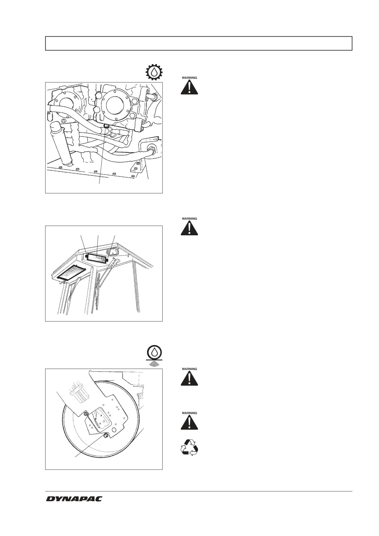
EVERY 1000 HOURS OF OPERATION (Every six months)
Pump drive
- Oil change
Observe caution when draining hot oil.
Wear gloves and safety goggles.
Use a receptacle that will hold at least 1.5 litre (1.6 qts)
for draining the oil.
Unscrew the drain plug (1) and also unscrew the
dipstick to allow the oil to flow freely, see under the
”Every 50 hours of operation” heading.
Wipe away any metal particles from the magnetic drain
plug, and refit the plug and its packing.
The gearbox holds 0.8 liter (0.85 qts). For topping off,
1
see under the ”Every 50 hours of operation” heading.
Fig. 46
Pump gearing
1. Drain plug
Fresh air filter - Replacement
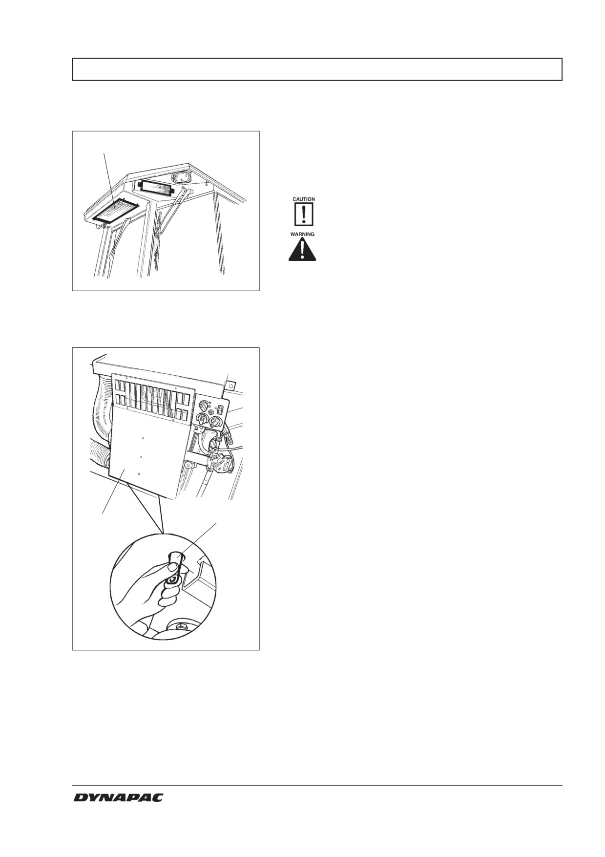
Use a stepladder to reach the filter (1).
2
1
2
There are two fresh-air filters (1), one on each side of
the cab. Unscrew the screws (2), take down the entire
housing and remove the filter insert.
Replace with new filters.
It may be necessary to change the filters more often if
the machine is run in a dusty environment.
Fig. 47
Cab
1. Fresh air filter (x2)
2. Screw (x2)
Drum
- Oil change (HF version)
Make sure there is adequate ventilation
(extraction) if the diesel engine is run in-
doors. Risk of carbon monoxide poisoning.
Drive the roller until the drain plug (1) - the large plug -
is straight down.
Switch off the engine and push the reserve/
parking brake knob.
Place a receptacle that will hold at least 20
liters (21 qts) under the plug. Save the oil and
dispose of it in an approved manner.
1
Remove the plug (1) and allow all the oil to run out. See
Fig.48
Drum, vibration side
under the heading ”Every 500 hours of operation” for
1. Drain plug
filling oil.
CC 422/HF/422C/CHF - CC 432 - CC 522/HF/522C/CHF M422EN5
29
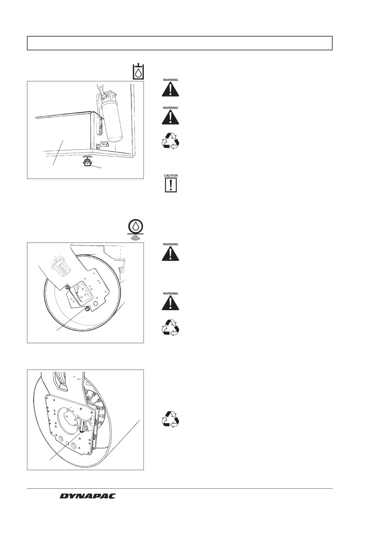
EVERY 2000 HOURS OF OPERATION (Yearly)
Hydraulic reservoir
- Changing the fluid
Place the roller on a level surface. Switch the
engine off and push in the reserve/parking-
brake knob for all checking and adjustments
on the roller, unless otherwise specified.
Observe caution when draining hot oil.
Wear gloves and safety goggles.
Place a receptacle that will hold at least 50
liters (53 qts) under the plug. Save the oil and
dispose of it in an approved manner.
Remove the drain plug (1) and allow all the oil to run
2
1
out, wipe and refit the drain plug.
Fill with fresh hydraulic fluid of the grade
Fig. 49
Engine compartment, right side
indicated in the Lubricant specification.
1. Drain plug
2. Hydraulic reservoir
Replace the hydraulic filter as described under the
heading ”Every 1000 hours of operation.”
Start the engine and operate the various hydraulic
functions. Check the level in the reservoir and top off
as required.
Drum - Oil change
Make sure that ventilation (extraction) is
adequate if the engine is run indoors. Risk
of carbon monoxide poisoning.
Drive the roller until the drain plug (1) - the large plug -
is straight down.
Switch off the engine and push the reserve/
parking brake knob.
Place a receptacle that will hold at least 20
liters (7 qts) under the plug. Save the oil and
1
dispose of it in an approved manner.
Fig. 50
Drum, vibration side
Remove the plug (1) and allow all the oil to run out. See
1. Drain plug
under the heading ”Every 500 hours of operation” for
filling oil.
CC 432 (four drum halves)
Position the roller with the drain plug (1) straight down.
Place a receptacle that will hold at least 7
liters (21 qts) under the plug. Save the oil and
dispose of it in an approved manner.
Remove the plug (1) and allow all the oil to run out. See
under the heading ”Every 500 hours of operation” for
filling oil.
1
Change the oil in all four drum halves.
Fig. 51
Drum, vibration side (CC432)
1. Drain plug
30
CC 422/HF/422C/CHF - CC 432 - CC 522/HF/522C/CHF M422EN5
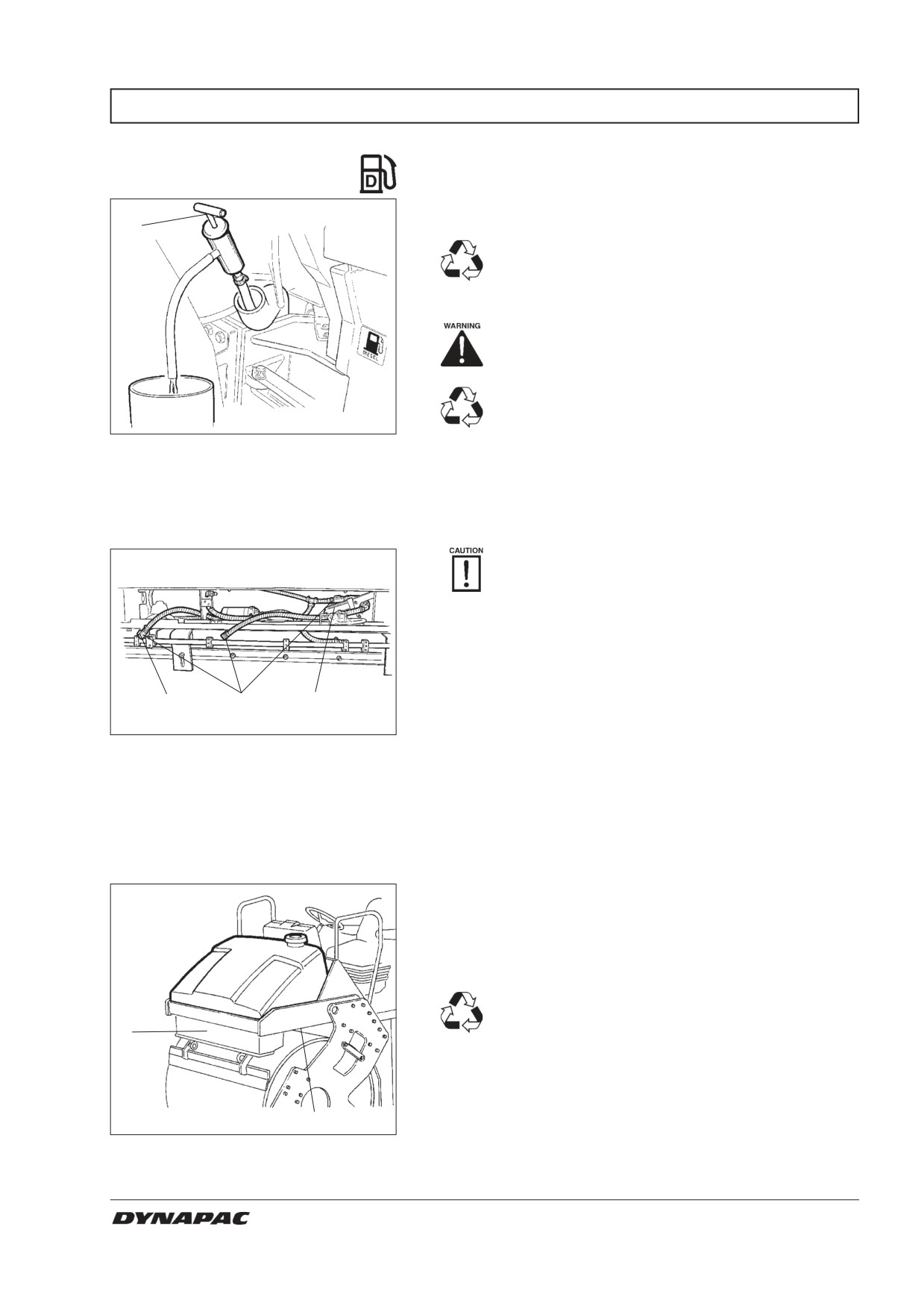
EVERY 2000 HOURS OF OPERATION (Yearly)
Fuel tank
- Cleaning
It is easiest to clean the tank when it is almost empty.
1
Pump out any bottom sediment with a suitable
pump; for example, an oil emptying pump.
Save the oil in a can and dispose of it in an
approved manner.
Remember the danger of fire when hand-
ling fuel.
The fuel tank is made of recyclable plastic
(polyethylene).
Fig. 52
Fuel tank
1. Oil emptying pump
Watering system
- Draining
Remember the risk of freezing during the
winter period and drain the tank, pump and
leads; or mix the water with a small amount of
environmentally friendly antifreeze.
The easiest way to empty the tank is to screw off the
filter housing (1) and disconnect the hoses by releasing
the quick-couplings.
2
3
1
There is also a drain cock (red square) under each
Fig. 53
Pump system
water tank.
1. Filter housing
2. Drain cock
Open the drain cock (2) to empty the water pump.
3. Quick-couplings
Water tank - Cleaning
Clean the tanks with water and a suitable detergent for
plastic surfaces.
Refit the filter housing (1) or the drain plug (2), fill with
water and check for tightness.
The water tanks are made of recyclable
plastic (polyethylene).
1
2
Fig. 54
Water tank
1. Pump system
2. Drain plug
CC 422/HF/422C/CHF - CC 432 - CC 522/HF/522C/CHF M422EN5
31
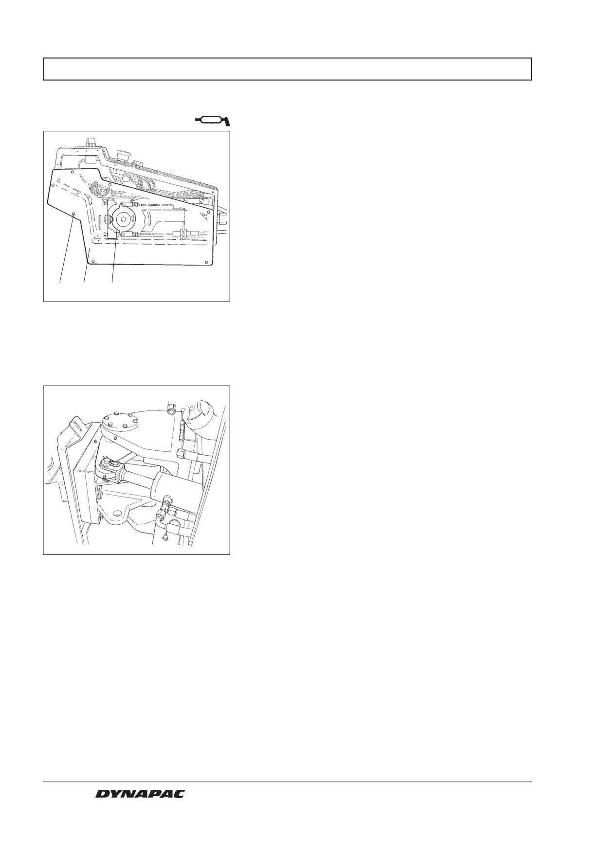
EVERY 2000 HOURS OF OPERATION (Yearly)
Forward/Reverse lever
- Lubrication
Remove the screws (1) and take off the plate (2).
Lubricate the sliding surface of the cam disc (3) with
grease.
Refit the plate (2) and the screws (1).
1
2
3
Fig. 55
Forward/Reverse lever
1. Screw
2. Plate
3. Cam disc
Steering joint - Check
Inspect the steering joint to detect any damage or
cracks.
Check and correct any loose bolts.
Check also for any stiffness and play.
Fig. 56
Steering joint
32
CC 422/HF/422C/CHF - CC 432 - CC 522/HF/522C/CHF M422EN5
EVERY 2000 HOURS OF OPERATION (Yearly)
Air conditioning
- Overhaul (Optional)
Regular inspection and maintenance are necessary to
1
ensure satisfactory long-term operation.
Clean the condenser element (1) free from dust with
the aid of compressed air. Blow from above.
The air jet could damage the flanges of the
elements if it is too powerful.
Wear protective goggles when working
with compressed air.
Inspect the fastening of the condenser element.
Fig. 57
Cab
1. Condenser element
Clean the cooler unit and the cooling elements (1) free
from dust with the aid of compressed air.
Inspect the system hoses for chafing. Make sure that
drainage from the cooling unit is unobstructed so that
condensation does not accumulate inside the unit.
Check the drain by squeezing the valves (2) underne-
ath the cab.
1
2
Fig. 58
Aircondition
1. Cooling element
2. Drain valve (x2)
CC 422/HF/422C/CHF - CC 432 - CC 522/HF/522C/CHF M422EN5
33
EVERY 2000 HOURS OF OPERATION (Yearly)
Compressor - Inspection
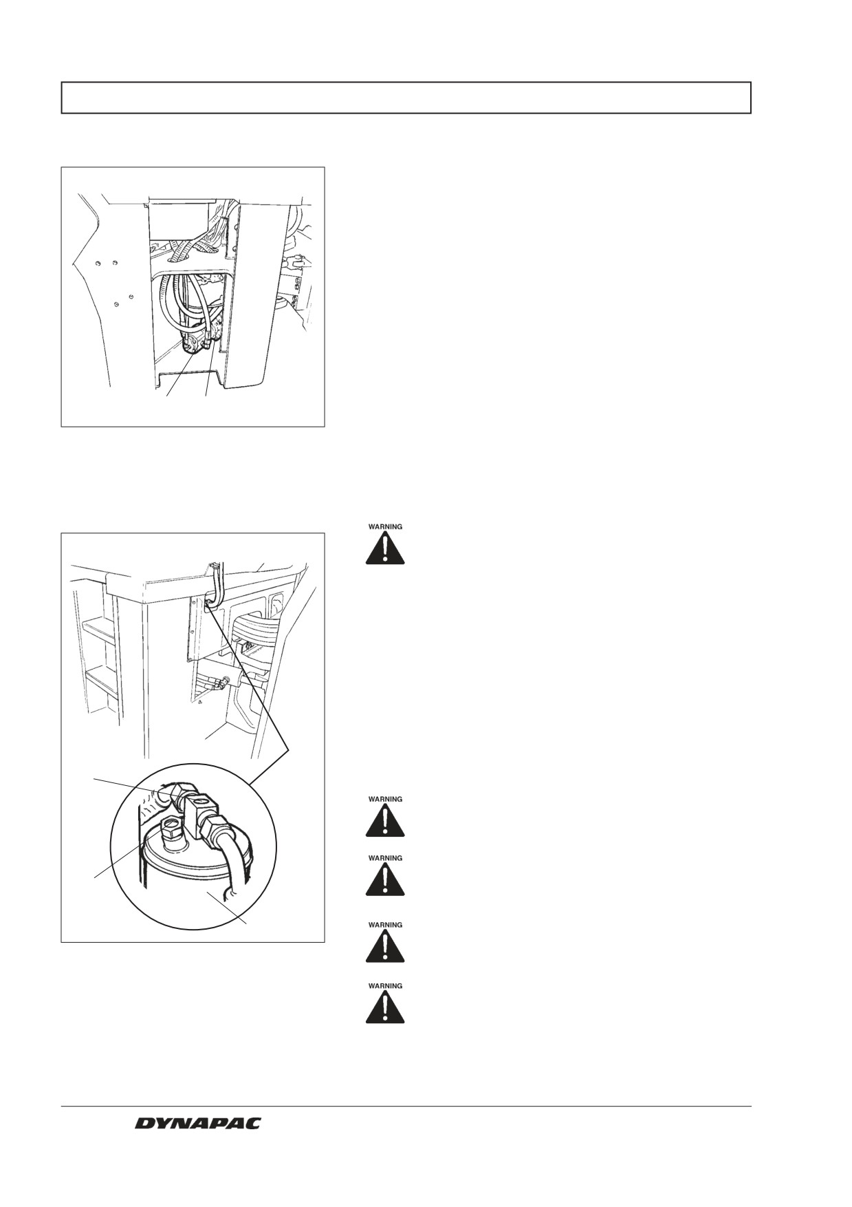
Inspect fastening of the compressor and hydraulic
motor. These components are located behind the steps
to the cab. Dismantle the steps.
The unit should be run at least five minutes every
week, if possible, to ensure that the rubber gaskets in
the system remain lubricated.
1
2
Fig. 59
Compressor
1. Hydraulic motor
2. Compressor
Drying filter - Inspection
Never work under the roller with the engi-
ne running. Park on a level surface, chock
the wheels and press the parking brake
control.
Open the engine hood while the unit is operating and
check in the sight glass (1) that no bubbles are visible
on the dryer filter. If bubbles are visible through the
sight glass, it is a sign that the level of refrigerant is too
low. If so, stop the unit. There is a risk of damage to the
unit if it is run with insufficient refrigerant.
Check the moisture indicator (2). The color should be
blue; if it is beige the dryer cartridge must be replaced
1
by an authorized service company.
The compressor will be damaged if the unit
is run with too little refrigerant.
2
Do not disconnect the hose coupling.
3
The cooling system is pressurized.
Incorrect handling can result in serious
Fig. 60
Dryer filter, underneath cab
personal injuries.
1. Sight glass
2. Moisture indicator
The system contains pressurized refriger-
3. Dessicator cartridge
ant. Releasing refrigerants into the air is
prohibited. The refrigerant circuit may only
be repaired by an authorized company.
34
CC 422/HF/422C/CHF - CC 432 - CC 522/HF/522C/CHF M422EN5
LONG-TERM STORAGE
The following instructions should be followed
for storage longer than one month:
The measures apply for a period of up to 6
months.
The items marked * must be restored before
using the roller.
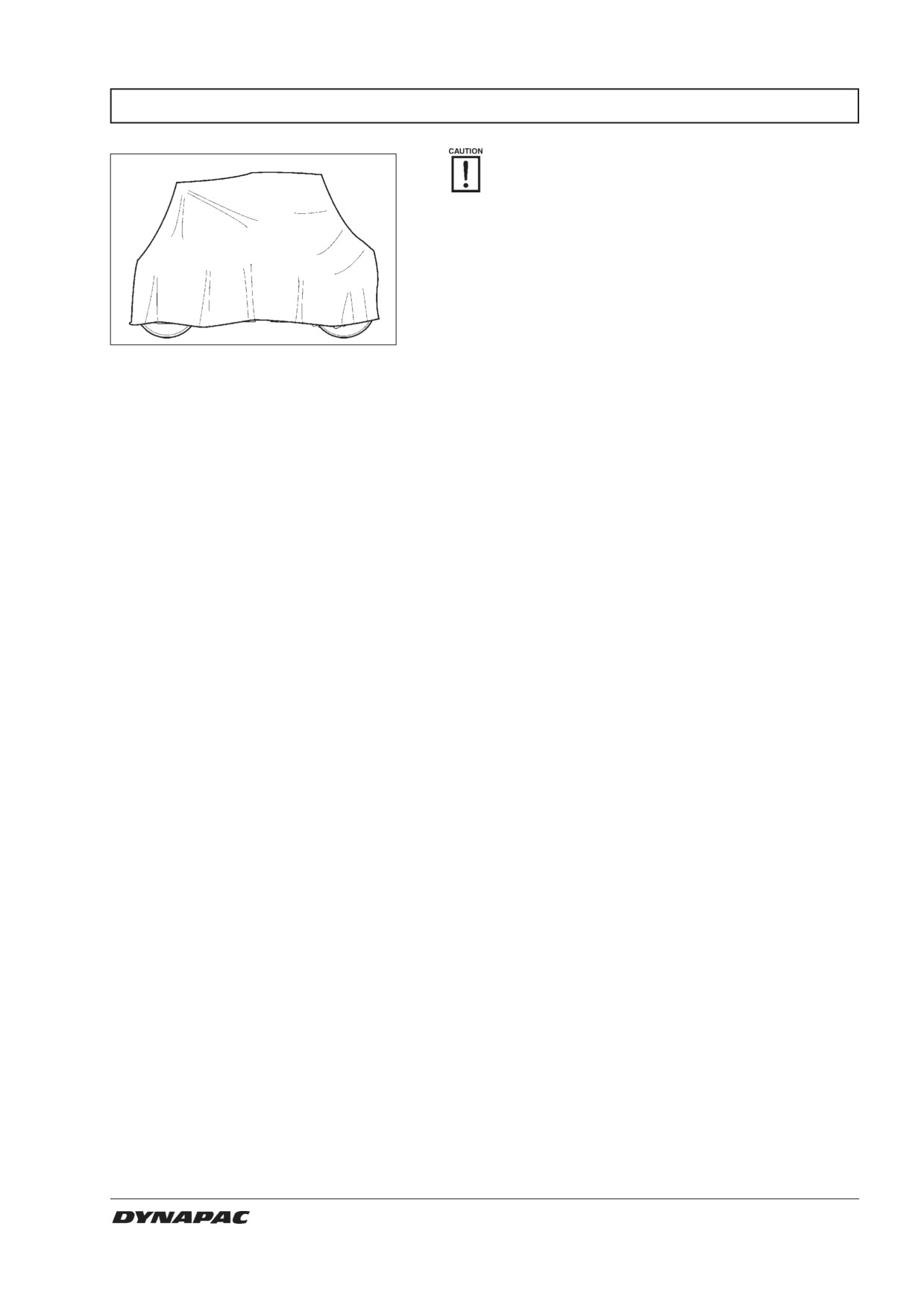
Fig. 61
Roller protected against the weather
Diesel engine
See manufacturer’s instructions in the engine
manual that accompanies the roller.
Battery
Remove the battery from the roller, clean it, check
that the electrolyte level is correct (see under the
heading ”Every 50 hours of operation”) and
tricklecharge the battery once a month.
Air cleaner, exhaust pipe
Cover the air cleaner (see under the heading ”Every
50 hours of operation” and also under the heading
”Every 1000 hours of operation”) or its opening with
plastic or tape, and also cover the exhaust opening.
This is necessary to prevent moisture from entering
the engine.
Fuel tank
Fill the fuel tank completely to prevent condensation.
Hydraulic reservoir
Fill the hydraulic reservoir to the uppermost level
mark, see under the heading ”Every 10 hours of
operation.”
Sprinkler system
Empty the water tank completely (see under the
heading ”Every 10 hours of operation”), also hoses,
filter housing and water pump. Remove all the
sprinkler nozzles (see under the heading ”Every 10
hours of operation”).
Steering cylinder, hinges, etc.
Lubricate bearings of the steering joint and both
bearings of the steering cylinder with grease (see
under the heading ”Every 50 hours of operation”).
Grease the piston rod of the steering cylinder with
inhibitor grease. Grease the hinges on doors to the
engine compartment and the cab, and also grease
both ends of the forward/reverse control (bright
parts) (see under the heading ”Every 500 hours of
operation”).
Tires (Combi)
Make sure that tire pressure is at least 200 kPa,
(2,0 kp/cm²) (29 psi).
Hoods, tarpaulin
Lower the instrument shield plate on the steering
*
column. Cover the entire roller with a tarpaulin. The
tarpaulin must be free from the ground. Store the
roller indoors if possible, preferably on premises with
an even temperature.
CC 422/HF/422C/CHF - CC 432 - CC 522/HF/522C/CHF M422EN5
35
SPECIAL INSTRUCTIONS
Standard oils and other
When they leave the factory, the systems and
components are filled with oil or fluid as indicated in the
recommended fluids
Lubrication specification and are thus suitable for
operation in ambient temperatures between -10°C and
+40°C (14°F - 104°F).
A maximum temperature of +35°C (95°F)
applies for biological hydraulic fluid.
Higher ambient temperature
The following recommendations apply for operation in
higher ambient temperatures up to a maximum of
above +50°C (122°F)
+50°C (122°F):
The diesel engine can be run at this temperature using
the normal oil, but for other components, the following
fluids must be used: Hydraulic system: mineral fluid
Shell Tellus TX100 or equivalent.
Temperature
The temperature limits apply to standard versions of
the roller.
Rollers that are fitted with additional equipment, such
as noise suppression, etc., may require extra observa-
tion in the higher temperature ranges.
High-pressure washing
Never aim a water jet directly at the cap of
the fuel tank or hydraulic reservoir. This is
especially important when using a high-
pressure jet.
Do not spray water directly on electric components or
the instrument panel. Put a plastic bag over the filler
cap of the fuel tank and secure with a rubber band.
This will prevent water from entering the venting hole
in the filler cap. This could otherwise cause
operational disturbance, for example, a clogged filter.
Fire fighting
In the event of fire in the machine, use an ABE powder
fire extinguisher if possible. A BE-type carbon dioxide
fire extinguisher may also be used.
Protective structure (ROPS),
If the roller is equipped with a protective structure
(ROPS, Roll Over Protective Structure), or protective
protective cab
cab, never subject the structure or cab to welding or
drilling. Never attempt to repair a damaged structure or
cab; they must be replaced with new ones.
Starting aid
When using an auxiliary battery to assist starting,
always connect the positive terminal of the auxiliary
battery to the positive terminal of the roller battery, and
negative to negative.
36
CC 422/HF/422C/CHF - CC 432 - CC 522/HF/522C/CHF M422EN5
ELECTRICAL SYSTEM, FUSES
Fuses
The electrical regulating system and control system are
protected by 24 fuses, located in the instrument panel
and in the engine compartment.
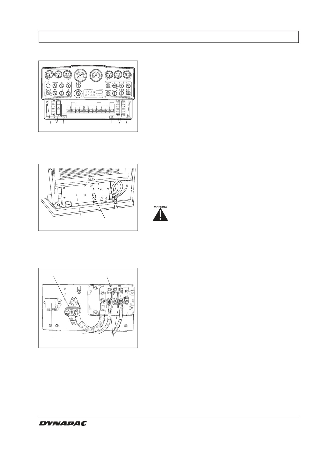
The four fuse boxes (1) are located behind the lower
instrument plate, which is opened by turning the four
quick-screws (2) a 1/4 turn counter-clockwise.
2 1 2
2
1
2
Fig. 62
Instrument panel
1. Fuse boxes
2. Quick-screws
Fuses in the engine compartment are located together
with the battery disconnecter, behind the left cover of
the engine compartment.
The machine is equipped with a 12 V electrical system
and an alternator.
Connect the battery to the correct polarity
(- to ground). The cable between battery-
2
1
and alternator must not be disconnec-
tedwhen the engine is running.
Fig. 63
Battery space
1. Battery disconnector
2. Main fuse panel
The main fuse panel is located behind the left cover of
1
2
the engine compartment.
The main fuses and start relay are easily accessible on
lowering the cover forward.
4
3
Fig. 64
Main fuse panel
1. Battery disconnecter
100A
2. Main fuse,,
Cab/standard electricity
125A
3. Preheating, engine
4. Start relay
CC 422/HF/422C/CHF - CC 432 - CC 522/HF/522C/CHF M422EN5
37
ELECTRICAL SYSTEM, FUSES
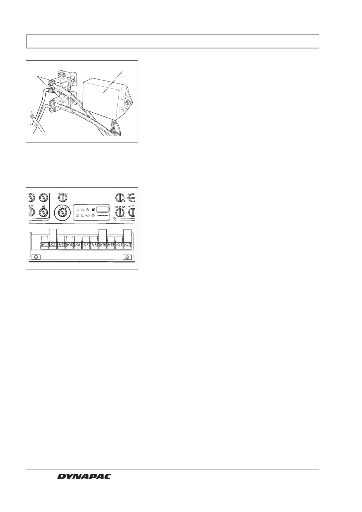
The control unit and relays for preheating the diesel
1
engine are located behind the left door of the engine
2
compartment on the wall adjacent to the rear drum.
Fig. 65
Engine compartment, left side
1. Control unit for preheating
2. Heating relay
Relays
K1
Lights relay
K2
Direction indicator relay
K3
Brakes relay
K4
Reverse alarm relay
K5
Fuel level relay
K7
Horn relay
K8
Sprinkler
K9
Main relay
K10
AVC
K11
Neutral switch
K12
VBS relay
Fig. 66
Instrument panel
38
CC 422/HF/422C/CHF - CC 432 - CC 522/HF/522C/CHF M422EN5
ELECTRICAL SYSTEM, FUSES
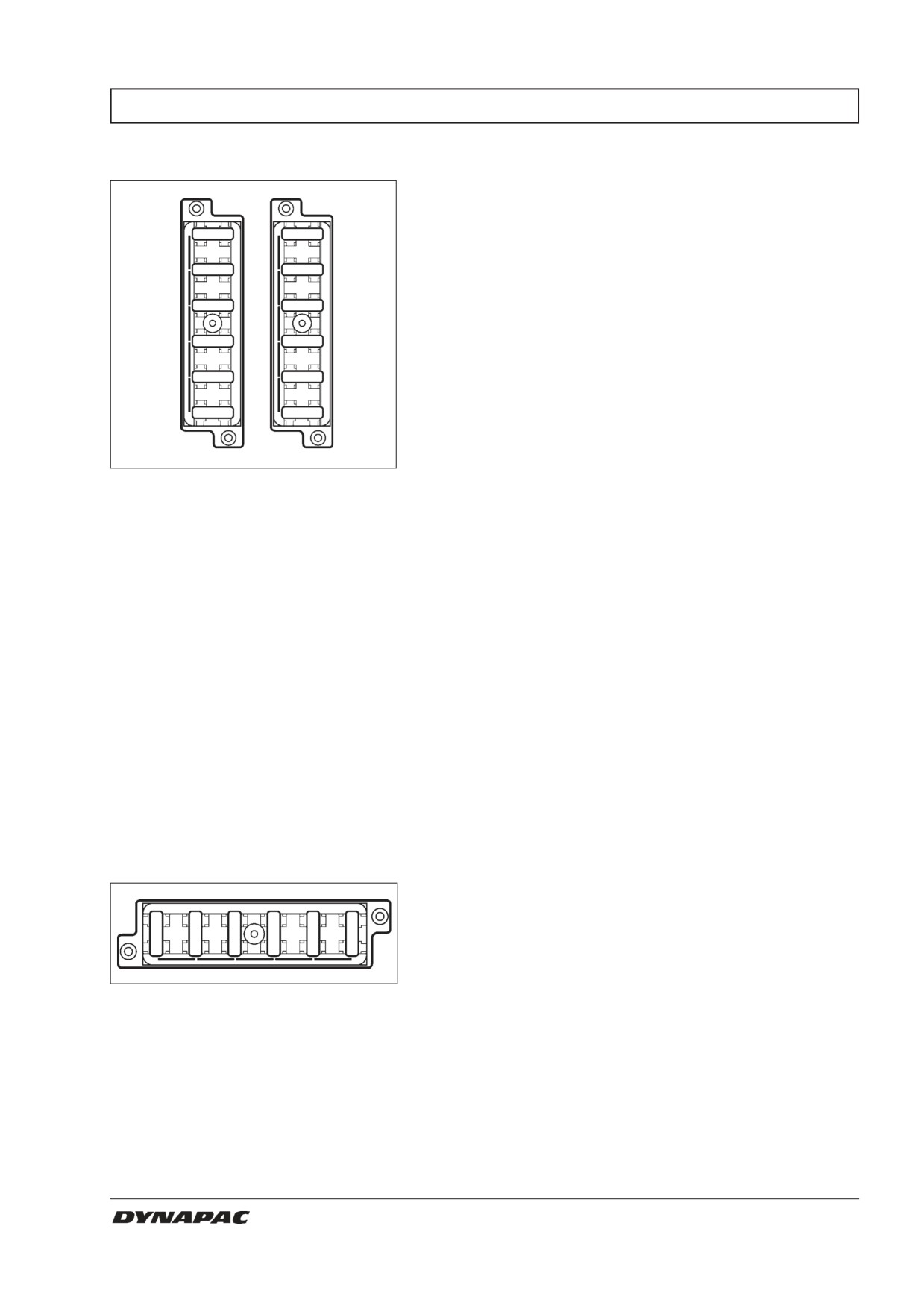
Fuses on the machine
The figure shows the rating and function of the different
fuses. All fuses are flat pin fuses..
1
7
2
8
3
9
4
10
5
11
6
12
Fig. 67
Fuse boxes, left side
Fuse boxes, right side
1. Vacant
7,5A
1. Brake valve, start relay, control relay cab
10A
2.
Direction indicators, main fuse
10A
2. Vibration relay, VBS
7,5A
3.
Left position lights, front and rear,
3A
3. Indicator panel
brake lights
7,5A
4. Horn
5A
4.
Right position lights, front and rear
7,5A
5. Vibration Front/Both/Rear, AVC-relay
5A
5.
Left direction indicator,
10A
6. Hazard beacon
front and rear, side blinkers
5A
6.
Right direction indicator,
front and rear, side blinkers
*/20A
7. Right working lights
7,5A
7. Sprinkler pump front
*/20A
8. Left working lights
7,5A
8. Sprinkler pump rear
7,5A
9. Left front headlight,
15,0A
9. Sprinkler system main fuse
instrument lighting
15,0A 10. Steering, offset up/down
7,5A 10. Right front headlight
7,5A 11. Reversing alarm
7,5A 11. Edge cutter, sprinkler Up/Down
7,5A 12. Instruments, voltmeter, temperature level,
12. Vacant
speedometer, tachometer, frequency meter
*/ If driving lights 10A
Fuses in the cab
The electrical system in the cab has an individual fuse
box located in the right front side of the cab roof. The
figure shows the rating and function of the different
1
´
3
4
5
6
fuses. All fuses are flat pin fuses.
Fig. 68
Fuse box in cab
15A
1. Rear cab working light
15A
2. Front cab working light,
drum headlight
5A
3. Cab interior lighting
20A
4. Heating/fresh-air fan
15A
5. Windshield wiper/washer
15A
6. Front windshield wiper/washer
CC 422/HF/422C/CHF - CC 432 - CC 522/HF/522C/CHF M422EN5
39