HUSQVARNA 61/268/272XP. Operator's manual
61/268/272XP
Operator´s manual
Please read these instructions carefully and make
sure you understand them before using the saw.
101 91 96-26
KEY TO SYMBOLS
Symbols on the chain saw:
CAUTION! Chain saws can be dangerous!
Careless or incorrect use can result in
serious or fatal injury to the operator or
others.
Please read the instructions carefully and
make sure you understand them before
using the saw.
Always wear:
• Approved protective helmet
• Approved hearing protection
• Protective glasses or visor
This product is in accordance with
applicable CE directives.
Other symbols/decals on the machine refer to
special certification requirements for certain
markets.
Symbols in the operator’s manual:
Switch off the engine by moving the stop
switch to the STOP position before
carrying out any checks or maintenance.
Always wear approved protective gloves.
Regular cleaning is required.
Visual check.
Protective glasses or a visor must be worn.
2 - English
CONTENTS
Before using a new saw
Contents
• Read the instructions carefully.
• Check cutting equipment is correctly fitted and adjusted. See
page 25.
Key to symbols
2
• Refuel and start the saw. Check the carburettor settings.
See pages 26-29.
Safety instructions
• Do not use the saw until sufficient chain oil has reached the
Personal protective equipment
4
chain, see page 14.
Chain saw safety equipment
4
IMPORTANT! If the carburettor mixture is too lean it greatly
Inspecting, maintaining and servicing
increases the risk of engine failure.
chain saw safety equipment
8
Poor maintenance of the air filter will cause carbon build-up on
the spark plug and lead to difficult starting.
Cutting equipment
10
If the chain is badly adjusted it will cause increased wear or
How to avoid kickback
16
damage to the bar, drive sprocket and chain.
General safety precautions
18
General working instructions
19
What is what?
What is what?
24
Under no circumstances should you modify
Assembly
the original design of the chain saw without
Mounting guide bar and chain
25
!
approval from the manufacturer. Always use
genuine spare parts. Unauthorized
Fuel handling
modifications or accessories may lead to
Fuelmix
26
serious injury or death.
Fuelling
27
Start and stop
Start and stop
28
A chain saw is a dangerous tool if used
Maintenance
carelessly or incorrectly and can cause
Carburettor
29
!
serious, even fatal injuries. It is very important
that you read and understand these
Starter device
30
instructions.
Air filter
31
Spark plug
31
Muffler
31
Adjusting the oil pump
31
Needle bearing maintenance
32
Cooling system
32
Heated handles (272XPG)
32
Winter use
32
Daily maintenance
33
Weekly maintenance
33
Monthly maintenance
33
Technical data
61
34
268
34
272XP
35
English -
3
SAFETY INSTRUCTIONS
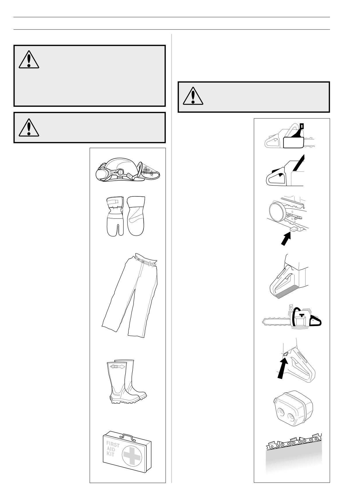
PERSONAL PROTECTIVE EQUIPMENT
CHAIN SAW SAFETY EQUIPMENT
This section explains the various safety features of the saw,
MOST CHAIN SAW ACCIDENTS HAPPEN
how they work, and basic inspection and maintenance you
WHEN THE CHAIN TOUCHES THE OPERA-
should carry out to ensure safe operation. (See the ”What is
TOR. You must wear approved protective
what?” section to find out where these components are on Your
equipment whenever you use a chain saw.
saw).
Personal protective equipment cannot
eliminate the risk of injury but it will reduce
the degree of injury if an accident does
NEVER USE A CHAIN SAW THAT HAS
happen. Ask your chain saw dealer for help
FAULTY SAFETY EQUIPMENT! Carry out the
in choosing the right equipment.
inspection, maintenance and service routines
listed in this section.
Long or continuous exposure to high noise
levels may cause permanent hearing
1
Chain brake and front
impairment. Always wear approved hearing
hand guard
protection when operating a chain saw.
• PROTECTIVE HELMET
• HEARING PROTECTION
• PROTECTIVE GLASSES
2
Throttle lock
OR VISOR
• GLOVES WITH
SAW PROTECTION
3
Chain catcher
4
Right hand guard
• PROTECTIVE TROUSERS
WITH SAW PROTECTION
5
Vibration damping system
6
Stop switch
• BOOTS WITH SAW
PROTECTION, STEEL
TOE-CAP AND NON-SLIP
SOLE
Generally clothes should be
close-fitting without restricting
7
Muffler
your freedom of movement.
• ALWAYS HAVE A FIRST
AID KIT NEARBY
8
Cutting equipment (see
”Cutting equipment”
section).
4 - English
SAFETY INSTRUCTIONS
2
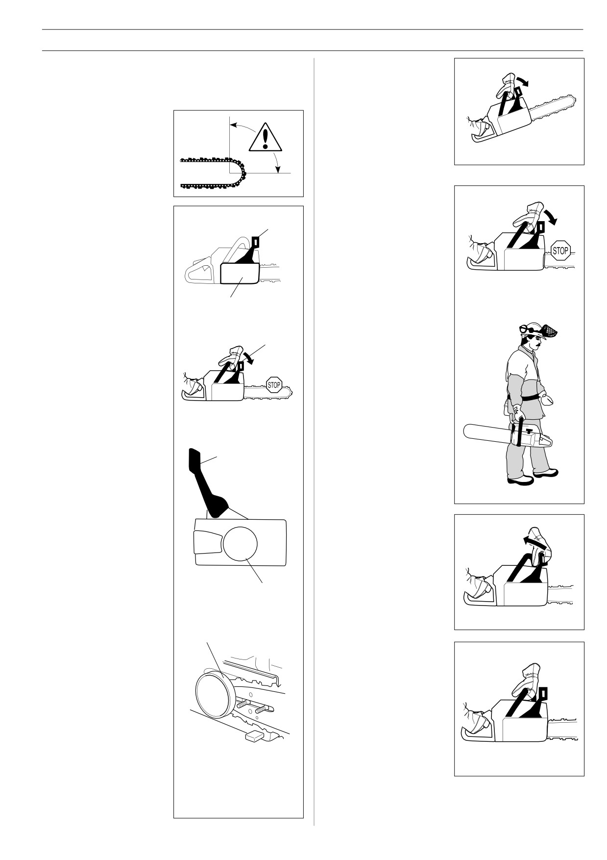
The front hand guard is
1
Chain brake and front hand guard
not designed solely to
YOUR chain saw is equipped with a chain brake that is desig-
activate the chain brake.
ned to stop the chain immediately if you get a kickback.
Another important safety
The chain brake reduces the risk of accidents, but only You can
feature is that it prevents
prevent them.
the chain from hitting your
left hand if you lose your
Take care when using your
grip on the front handle.
saw and make sure the
kickback zone of the bar
never touches any object.
3
You can also use the
chain brake as a
1
The chain brake (A) can
temporary brake when you
either be activated
change position or if you
B
manually (by your left
put the saw down for a
hand) or automatically by
short time. You should
the inertia release
also apply the chain brake
mechanism (a free-
manually if there is a risk
swinging pendulum). On
of the chain accidentally
most of our models the
hitting anyone or anything
front hand guard acts as a
close by.
A
counterweight in case of
kickback.
B
The brake is applied
when the front hand
guard (B) is pushed
forwards.
B
4
To release the chain brake
pull the front hand guard
This movement activates
backwards, towards the
a spring-loaded
front handle.
mechanism that tightens
the Brake Band (C)
around the engine drive
system (D) (Clutch Drum).
C
D
5
As mentioned in section A,
kickback can be very
sudden and violent.
Most kickbacks are
minor and do not always
activate the chain brake.
If this happens you
should hold the chain
saw firmly and not let
go.
English -
5
SAFETY INSTRUCTIONS
6
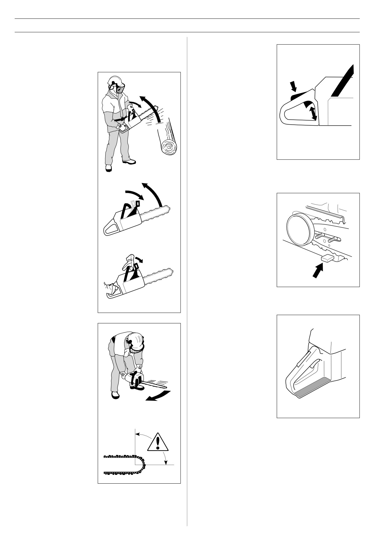
The way the chain brake is triggered, either manually or
2
Throttle lock
automatically, depends on the force of the kickback and the
The throttle lock is designed
position of the chain saw in relation to the object that the
to prevent accidental opera-
kickback zone of the bar strikes.
tion of the throttle control.
When you press the lock (A)
(i.e. when you grasp the
If you get a violent
A
handle) it releases the throttle
kickback while the
trigger (B).
kickback zone of the bar
When you release the handle
is farthest away from you
the throttle trigger and the
the chain brake will be
throttle lock both move back
activated by the
to their original positions. This
movement of the
movement is controlled by two
counterweight (INERTIA
independent return springs.
ACTIVATED).
B
This arrangement means that
the throttle control is
automatically locked at the
idle setting when you release
the handle.
3
Chain catcher
The chain catcher is designed
If the kickback is less
to catch the chain if it snaps or
violent or the kickback
jumps off. This should not
zone of the bar is closer
happen if the chain is properly
to you the chain brake will
tensioned (see section on
be activated manually by
”Assembly”) and if the bar and
the movement of your left
chain are properly serviced
hand.
and maintained.
(See section on ”General
working instructions”).
4
Right hand guard
Apart from protecting your
hand if the chain jumps or
7
During felling your left
snaps, the right hand guard
hand grasps the front
stops branches and twigs
handle in such a way that
from interfering with your grip
it cannot activate the front
on the rear handle.
hand guard. In this
position the chain brake
can only be activated by
the inertia action of the
counterweight.
The inertia activated
chain brake increases
your safety but there are
certain factors to
remember (see point 6
above).
6 - English
SAFETY INSTRUCTIONS
5
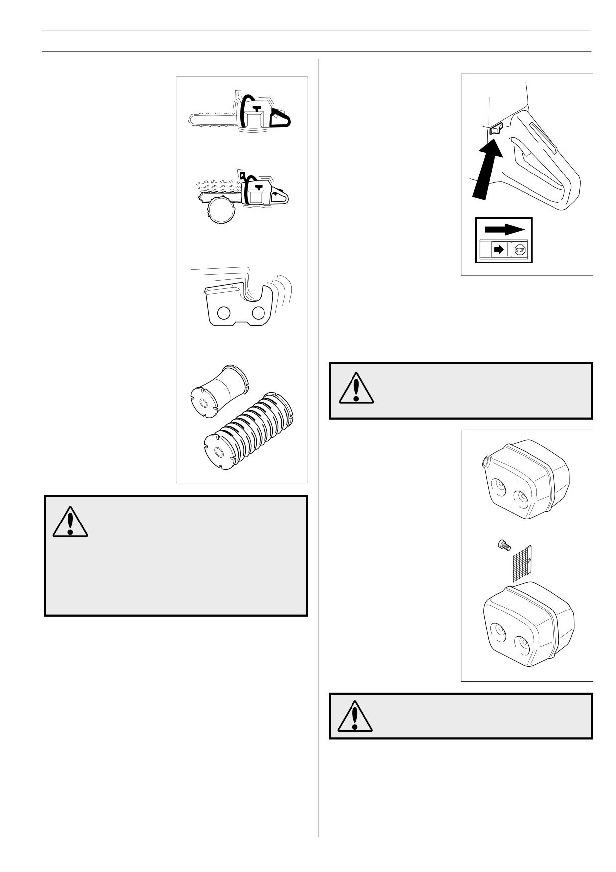
Vibration damping system
6
Stop switch
Your chain saw is equipped
Use the stop switch to switch
with a vibration damping
off the engine.
system that is designed to
minimise vibrations and make
operation easier.
When you use a chain saw
vibrations are generated by
the uneven contact between
the chain and the wood you
are cutting.
Cutting hardwoods (most
broadleaf trees) creates more
vibration than cutting
softwoods (most conifers).
Cutting with a chain that is
blunt or faulty (wrong type or
badly sharpened, see section
D) will increase the vibration
7
Muffler
level.
The muffler is designed to keep noise levels to a minimum and
to direct exhaust fumes away from the user.
The vibration damping system
The exhaust fumes from the engine are hot
reduces the vibrations
and may contain sparks which can start a fire.
transmitted from the engine
Never start the saw indoors or near
and chain to the handles of
combustible material!
the chain saw. The body of
the saw, including the cutting
In areas with a hot, dry
equipment, is insulated from
climate there is a high risk of
the handles by vibration
forest fires. These areas are
damping units.
sometimes controlled by
legislation and requirements
that among other things the
muffler must be equipped with
Overexposure to vibration can lead to
an approved type of spark
circulatory damage or nerve damage in people
arrestor mesh.
who have impaired circulation.
Contact your doctor if you experience
For mufflers it is very
symptoms of overexposure to vibration.
important that you follow the
These symptoms include numbness, loss of
instructions on checking,
feeling, tingling, pricking, pain, loss of
maintaining and servicing your
strength, changes in skin colour or condition.
saw (see the section on
These symptoms normally appear in the
”Inspecting, maintaining and
fingers, hands or wrists.
servicing chain saw safety
equipment”).
The muffler gets very hot in use and remains
so for a short time afterwards. DO NOT
TOUCH THE MUFFLER IF IT IS HOT!
English -
7
SAFETY INSTRUCTIONS
3
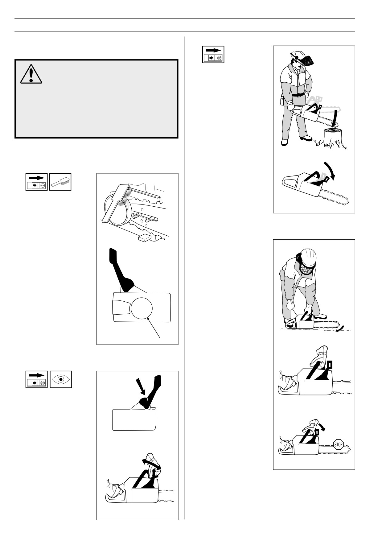
Checking the inertia brake release
Inspecting, maintaining and servicing
chain saw safety equipment
SPECIAL TRAINING IS REQUIRED to service
Hold the chain saw over a
and repair chain saws. This is especially true
stump or other firm object.
of chain saw safety equipment. If your chain
Let go of the front handle
saw fails any of the checks described below
so that the bar falls onto
take it to your SERVICE AGENT.
the stump.
When you buy any of our products we
guarantee the availability of professional
repairs and service. If the retailer who sells
your saw is not a SERVICING DEALER, ask
him for the address of your nearest SERVICE
AGENT.
1
Chain brake and front hand guard
1
Checking brake band wear
When the bar hits the
stump the brake should
be applied.
Brush off any sawdust,
resin and dirt from the
chain brake and clutch
drum. Dirt and wear can
impair operation of the
brake.
4
Checking the brake trigger
Start the chain saw and
place it on firm ground.
Make sure the chain does
not touch the ground or
any other object.
Regularly check that the
brake band is at least 0.6
mm thick at its thinnest
point.
2
Checking the front hand guard
Grasp the saw firmly,
wrapping your fingers and
thumbs around the
handles.
A Make sure the
FRONT HAND GUARD
is not damaged and
Apply full throttle and
that there are no visible
activate the chain brake
defects such as cracks.
by tilting your wrist
forward onto the front
hand guard. Do not let go
of the front handle.
The chain should stop
immediately.
B Move the front hand
guard forwards and
back to make sure it
runs freely and that it is
securely anchored to
the clutch cover.
8 - English
SAFETY INSTRUCTIONS
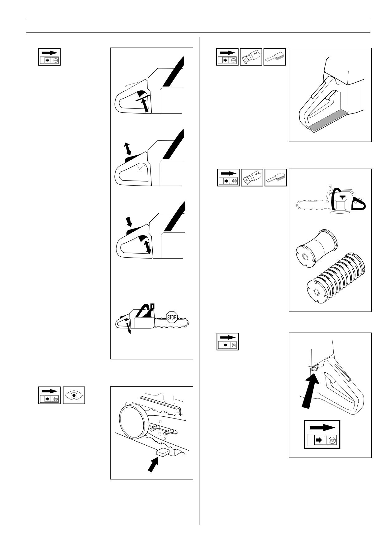
2
Throttle lock
4
Right hand guard
1
Make sure the throttle
Check that the right hand
control is locked at the
guard is not damaged and
idle setting when you
that there are no visible
release the throttle lock.
defects, such as cracks.
2
Press the throttle lock and
5
Vibration damping system
make sure it returns to its
original position when you
release it.
Regularly check the
vibration damping units
for cracks or deformation
3
Check that the throttle
control and throttle lock
move freely and that the
return springs work
properly.
Make sure the vibration
damping units are
securely attached to the
engine unit and handles.
4
Start the saw and apply
full throttle. Release the
throttle control and check
that the chain stops and
remains stationary. If the
chain rotates when the
6
Stop switch
throttle is on idle setting
you should check the
carburettor idle
adjustment. See the
section on ”Maintenance”.
Start the engine and
make sure the engine
stops when you move the
stop switch to the stop
3
Chain catcher
setting.
Check that the CHAIN
CATCHER is not
damaged and is firmly
attached to the body of
the saw.
English -
9
SAFETY INSTRUCTIONS
7
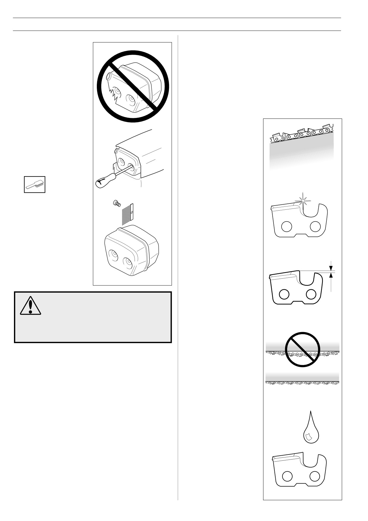
Muffler
CUTTING EQUIPMENT
Never use a chain saw
This section describes how to choose and maintain your cutting
that has a faulty muffler.
equipment in order to:
• Reduce the risk of kickback.
• Reduce the risk of the chain breaking or jumping.
• Obtain maximum cutting performance.
• Extend the life of cutting equipment.
The 5 basic rules
1
Only use cutting
equipment
recommended by us!
Regularly check that the
See the ”Technical data”
muffler is securely
section.
attached to the chain saw.
2
Keep the chain cutting
If the muffler on your saw
teeth properly
is fitted with a spark
sharpened! Follow our
arrestor mesh this must
instructions and use the
be cleaned regularly. A
recommended file
blocked mesh will cause
gauge. A damaged or
the engine to overheat
badly sharpened chain
and may lead to serious
increases the risk of
damage.
accidents.
Never use a muffler if
the spark arrestor mesh
is missing or defective.
3
Maintain the correct
raker clearance! Follow
our instructions and
NEVER USE A CHAIN SAW WITH FAULTY
use the recommended
SAFETY EQUIPMENT. CARRY OUT THE
raker gauge. Too large a
CHECKS AND MAINTENANCE MEASURES
clearance increases the
DESCRIBED IN THIS SECTION. IF YOUR
risk of kickback.
CHAIN SAW FAILS ANY OF THESE CHECKS
CONTACT YOUR SERVICE AGENT TO GET IT
REPAIRED.
4
Keep the chain properly
tesioned! If the chain is
slack it is more likely to
jump off and lead to
increased wear on the
bar, chain and drive
sprocket.
5
Keep cutting equipment
well lubricated and
properly maintained!
A poorly lubricated chain
is more likely to break and
lead to increased wear on
the bar, chain and drive
sprocket.
10 - English
SAFETY INSTRUCTIONS
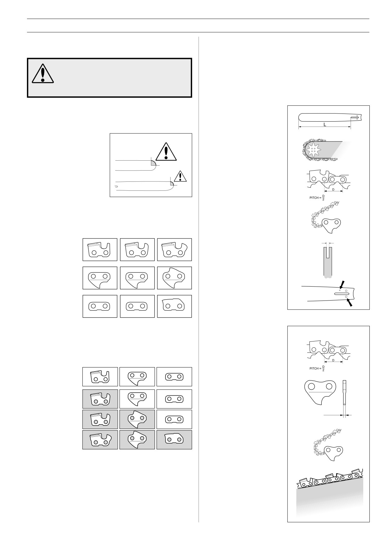
1
Cutting equipment designed to minimise
C Some terms that describe the bar and chain
When the cutting equipment supplied with your saw becomes
kickback
worn or damaged you will need to replace it. Use only the type
of bar and chain recommended by us. See the ”Technical data”
Faulty cutting equipment or the wrong
section to find out which equipment is recommended for your
combination of bar and chain increases the
saw.
risk of kickback. Use only the bar and chain
combinations recommended in the ”Technical
data” section.
Bar
The only way to avoid kickback is to make sure that the kick-
•
LENGTH (inches/cm)
back zone of the bar never touches anything.
By using cutting equipment with “built-in” kickback protection
•
NUMBER OF TEETH ON
and keeping the chain sharp and well-maintained you can
BAR TIP SPROCKET (T).
reduce the effects of kickback.
Small number = small tip
radius = low-kickback
A Bar
The smaller the tip radius the
•
CHAIN PITCH (inches)
smaller the kickback zone and
The spacing between the
the lower the chance of
drive links of the chain must
kickback.
match the spacing of the
teeth on the bar tip sprocket
and drive sprocket.
•
NUMBER OF DRIVE LINKS
The number of drive links is
B Saw chain
determined by the length of
A saw chain is made up of a number of links, which are
the bar, the chain pitch and
available in standard and low-kickback versions.
the number of teeth on the
bar tip sprocket.
None
Standard Low-kickback
•
BAR GROOVE WIDTH
(inches/mm)
CUTTING LINK
The groove in the bar must
match the width of the chain
drive links.
DRIVE LINK
•
SAW CHAIN OIL HOLE
AND HOLE FOR CHAIN
TENSIONER
The bar must be matched to
the chain saw design.
SIDE LINK
Saw chain
Combining these links in different ways gives different degrees
of kickback reduction. In terms of kickback reduction alone, four
• SAW CHAIN PITCH
different types of link are available.
(=PITCH) (inches)
Kickback reduction
Cutting link
Drive link
Side link
LOW
• DRIVE LINK WIDTH (mm/
inches)
STANDARD
• NUMBER OF DRIVE LINKS
HIGH
EXTRA HIGH
• LEVEL OF KICKBACK
REDUCTION
The level of kickback
reduction offered by a chain
is indicated by its model
number.
See the ”Technical data”
section to find the model
numbers of chains that are
recommended for use with
your saw.
English -
11
SAFETY INSTRUCTIONS
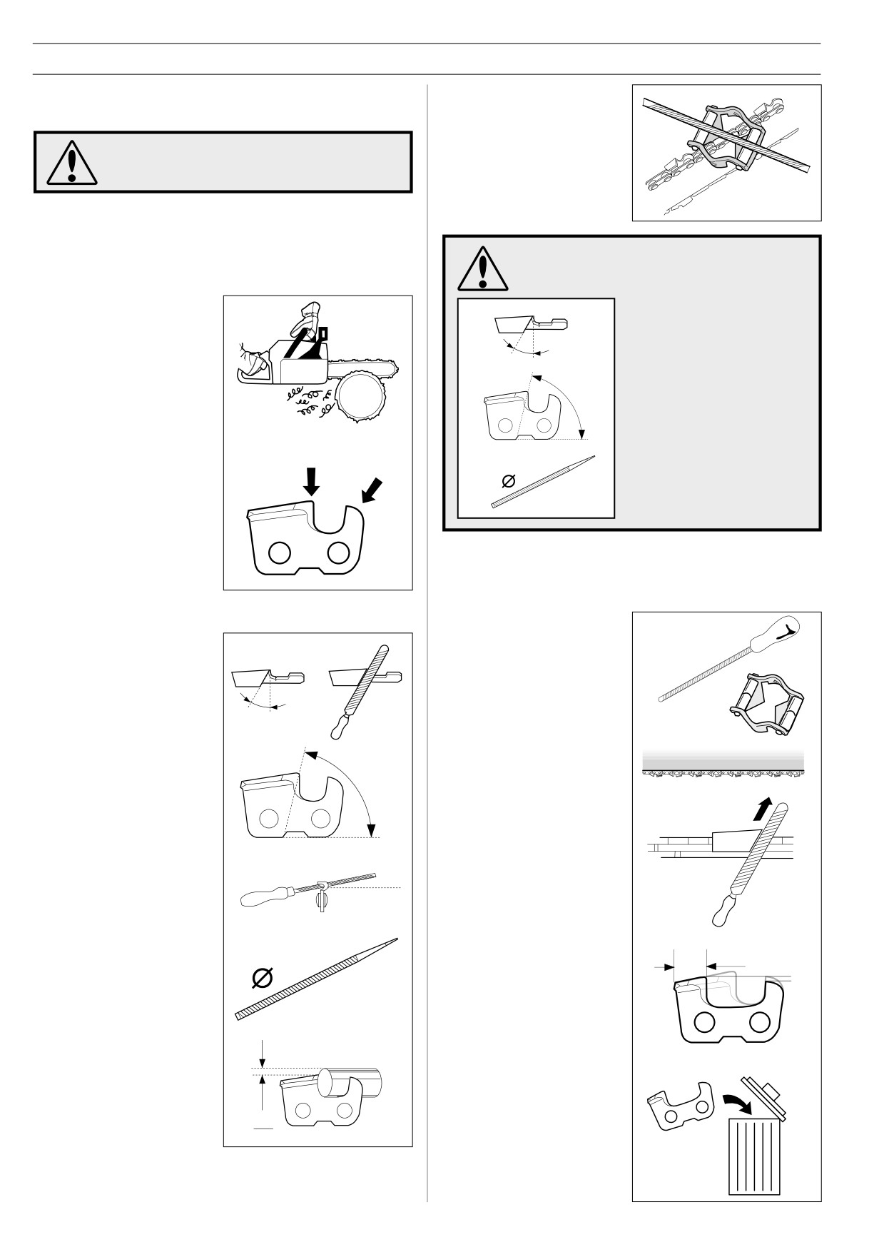
It is very difficult to sharpen a
2
Sharpening your chain and adjusting
chain correctly without the
raker clearance
right equipment. We
recommend you use a file
The risk of kickback is increased with a badly
gauge. This will help you
sharpened chain!
obtain the maximum kickback
reduction and cutting
performance from your chain.
A General information on sharpening cutting teeth
• Never use a blunt chain. When the chain is blunt you have to
exert more pressure to force the bar through the wood and
the cuttings will be very small. If the chain is very blunt it will
The following faults will increase the risk of
not produce any cuttings at all, just wood powder.
kickback considerably.
• A sharp chain eats its way
•
FILE ANGLE TOO
through the wood and
LARGE
produces long, thick
cuttings.
•
CUTTING ANGLE
TOO SMALL
A
• The cutting part of the chain
B
•
FILE DIAMETER
is called the CUTTING LINK
TOO SMALL
and this consists of a
CUTTING TOOTH (A) and
the RAKER LIP (B). The
cutting depth is determined
by the difference in height
between the two.
B Sharpening cutting
teeth
• When you sharpen a cutting tooth there are five important
To sharpen cutting teeth you
factors to remember.
will need a ROUND FILE and
a FILE GAUGE. See the
”Technical data” section for
FILING ANGLE
information on the size of file
and gauge that are
recommended for your saw
chain.
1
Check that the chain is
CUTTING ANGLE
correctly tensioned. A
slack chain is difficult to
sharpen correctly.
FILE POSITION
2
Always file cutting teeth
from the inside face,
reducing the pressure on
the return stroke.
min 4 mm
(0,16")
ROUND FILE DIAMETER
File all the teeth on one
side first, then turn the
saw over and file the
teeth on the other side.
FILE DEPTH
3
File all the teeth to the
same length. When the
length of the cutting teeth
1
is reduced to 4 mm
5
(0,16") the chain is worn
out and should be
See the ”Technical data” section for information about
replaced.
sharpening your saw chain.
12 - English
SAFETY INSTRUCTIONS
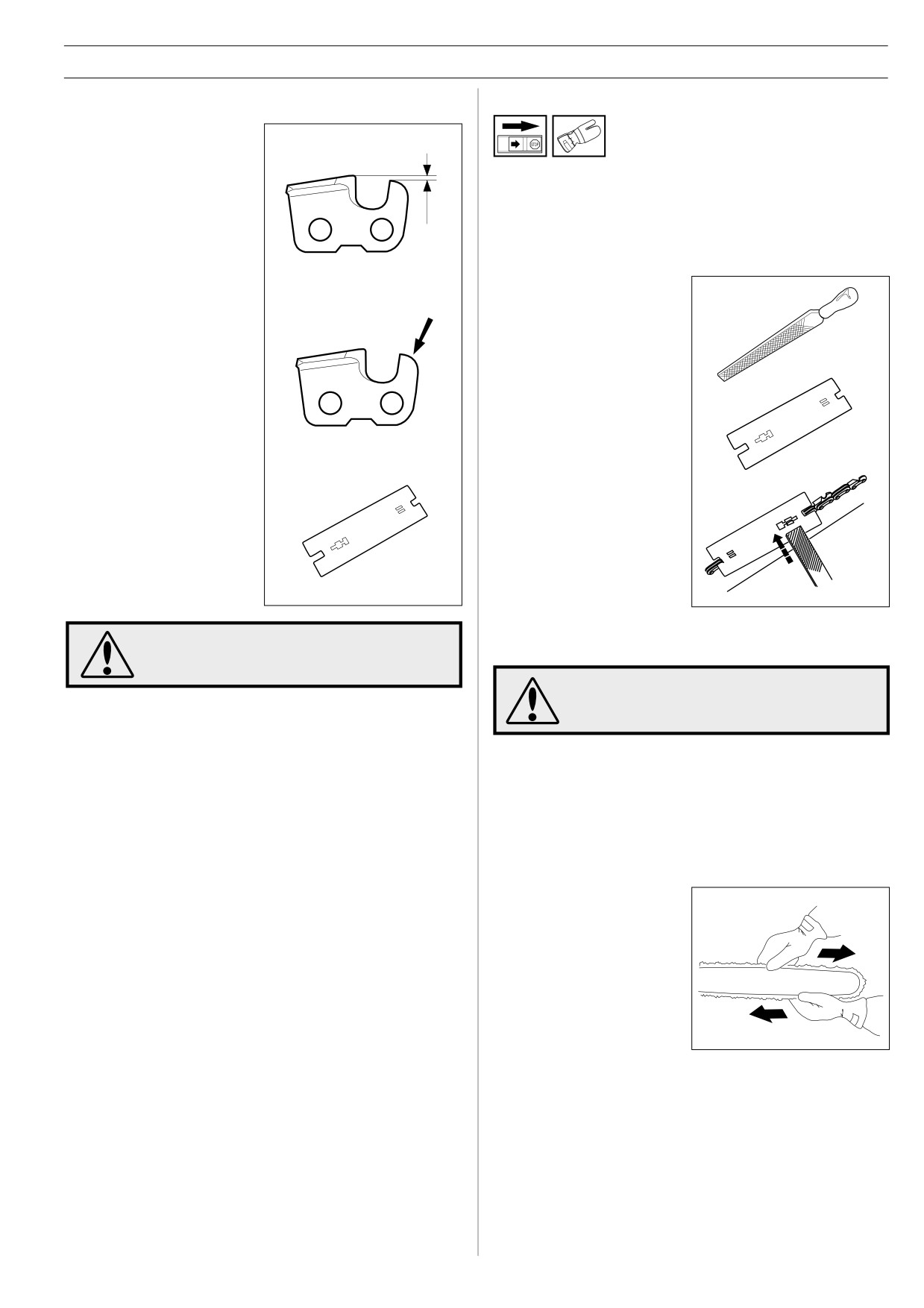
C General advice on setting raker clearance
D Setting the raker clearance
• When you sharpen the
cutting teeth you reduce the
RAKER CLEARANCE
(cutting depth). To maintain
• Before setting the raker clearance the cutting teeth should be
cutting performance you
newly sharpened.
must file back the raker
We recommend that you adjust the raker clearance every
teeth to the recommended
third time you sharpen the chain. NOTE! This
height.
recommendation assumes that the length of the cutting teeth
is not reduced excessively.
See the ”Technical data”
section to find the raker
• To adjust the raker
clearance for your saw
clearance you will need a
chain.
FLAT FILE and a RAKER
GAUGE.
• On a low-kickback cutting
link the front edge of the
raker lip is rounded. It is
• Place the gauge over the
very important that you
raker lip.
maintain this radius or bevel
when you adjust the raker
clearance.
• Place the file over the part
• We recommend the use of a
of the lip that protrudes
raker gauge to achieve the
through the gauge and file
correct clearance and bevel
off the excess. The
on the raker lip.
clearance is correct when
you no longer feel any
resistance as you draw the
file over the gauge.
The risk of kickback is increased if the raker
3
Tensioning the chain
clearance is too large!
A slack chain may jump off and cause serious
or even fatal injury.
• The more you use a chain the longer it becomes. It is
therefore important to adjust the chain regularly to take up the
slack.
• Check the chain tension every time you refuel.
NOTE! A new saw chain has a running-in period during which
you should check the tension more frequently.
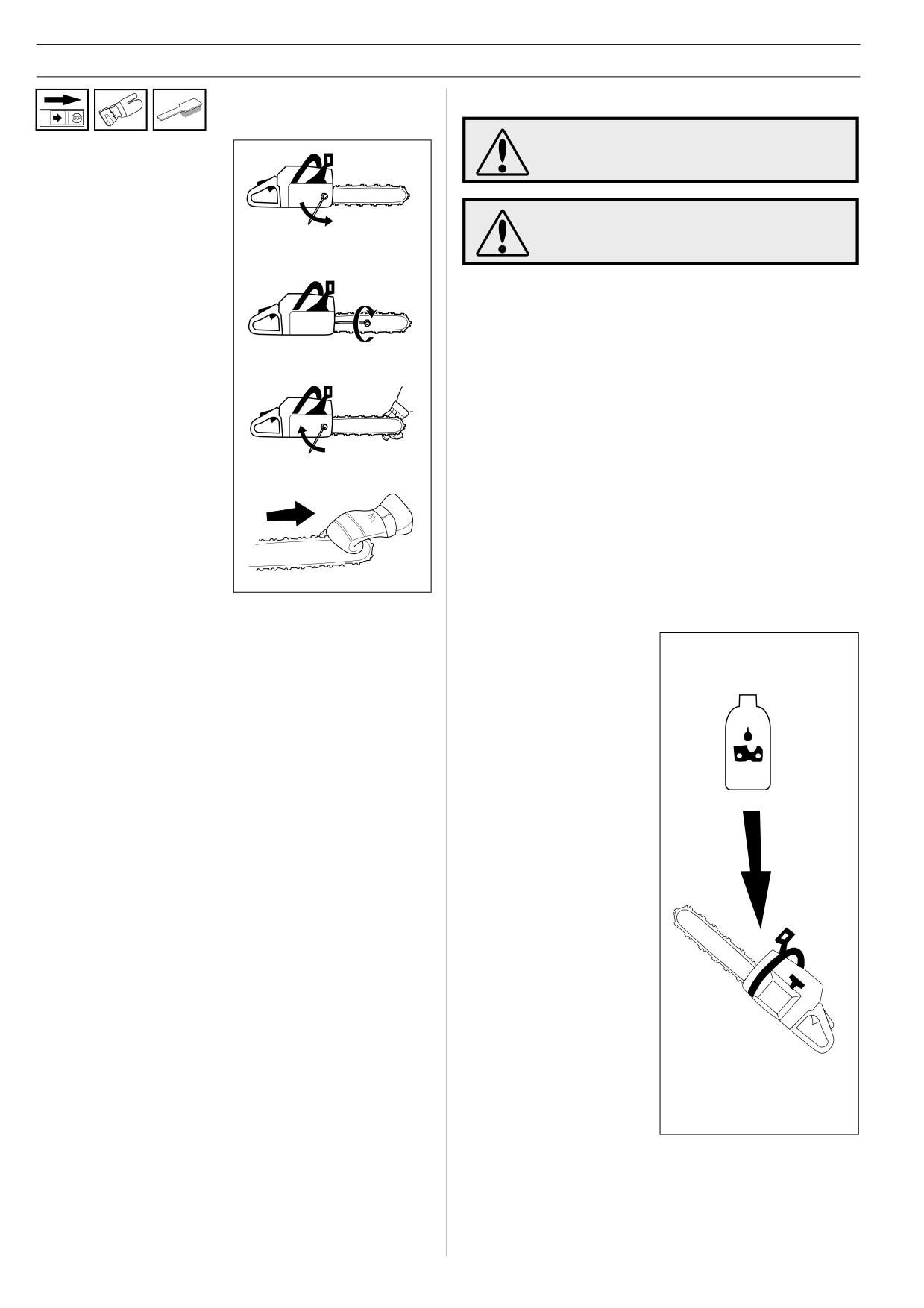
• Tension the chain as tightly
as possible, but not so tight
that you cannot pull it round
freely by hand.
English -
13
SAFETY INSTRUCTIONS
4
Lubricating cutting equipment
Poor lubrication of cutting equipment may
1
Undo the bar nuts that
cause the chain to snap and lead to serious,
hold the clutch cover and
even fatal injuries.
chain brake, using the
combination spanner.
Then tighten the nuts by
Prolonged inhalation of exhaust gases from
hand as tight as you can.
the engine, chain lubrication oil mist and/or
saw dust can be unhealthy.
2
Raise the tip of the bar
A Chain oil
and stretch the chain by
• Chainsaw chain oil must demonstrate good adhesion to the
tightening the chain
chain and also maintain its flow caracteristics regardless of
tensioning screw using
whether it is warm summer or cold winter weather.
the combination spanner.
Tighten the chain until it
• As a chainsaw manufacturer we have developed an optimal
not hang slack on the
chain oil which, with its vegetable oil base, is also
underside of the bar.
biodegradable. We recommend the use of our own oil for
both maximum chain life and to minimise environmental
damage.
3
Use the combination
• If our own chain oil is not available, standard chain oil is
spanner to tighten the bar
nuts while lifting the tip of
recommended.
the bar at the same time.
Check that you can pull
• In areas where oil specifically for lubrication of saw chains is
the chain round freely by
unavailable, ordinary EP 90 transmission oil may be used.
hand and that it is not
slack on the bottom of the
• Never use waste oil!
bar.
This is dangerous for yourself, the saw and the environment.
The position of the chain tensioning screw varies from
model to model. See the” What is what” section to find out
B Filling with chain oil
where it is on your saw.
• All our chain saws have an
automatic chain lubrication
system. On some models
the oil flow is also
adjustable.
•
The sizes of the chain oil
tank and fuel tank have
been chosen so that the
saw will run out of fuel
before running out of oil.
This means that you should
never run with a dry chain.
However, this safety feature
requires that you use the
right sort of chain oil (if the
oil is too thin it will run out
before the fuel), and that
you adjust the carburettor
as recommended (a weak
mixture may mean that the
fuel lasts longer than the
oil). You should also use the
recommended cutting
equipment (a bar that is too
long will use more chain oil).
The above conditions also
apply to models with an
adjustable oil pump.
14 - English
SAFETY INSTRUCTIONS
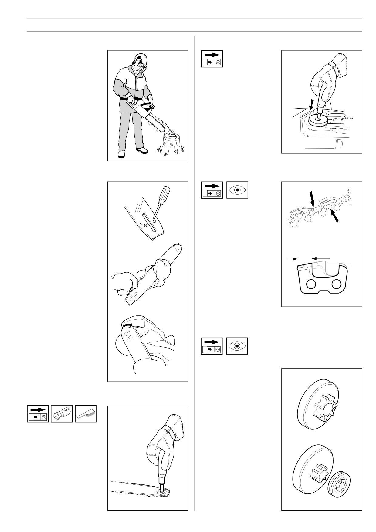
C Checking chain lubrication
E Lubricating the clutch drum bearing
• Check the chain lubrication
each time you refuel.
Aim the tip of the saw at a
light coloured surface about
• Between the engine drive
20 cm away. After 1 minute
shaft and the clutch drum is
running at 3/4 throttle you
a needle bearing that must
should see a distinct line of
be lubricated daily. Use the
oil on the light surface.
specially designed grease
gun and a good quality
bearing grease.
F Checking wear on cutting equipment
If the chain lubrication is not working:
Saw chain
1
Check that the oil channel
in the bar is not
obstructed. Clean if
necessary.
Check the saw chain daily for:
• Visible cracks in rivets and
links.
• Whether the chain is stiff.
• Whether rivets and links are
badly worn.
2
Check that the groove in
We recommend you
min 4 mm
the edge of the bar is
compare the existing chain
(0,16")
clean. Clean if necessary.
with a new chain to decide
how badly it is worn.
3
Check that the bar tip
sprocket turns freely and
When the length of the
that the lubricating hole in
cutting teeth has worn down
the tip is not blocked.
to only 4 mm the chain must
Clean and lubricate if
be replaced.
necessary.
If the chain lubrication
G Chain drive sprocket
system is still not working
after carrying out the
above measures you
should contact your
service agent.
The clutch drum is fitted with one of the following drive
sprockets:
A SPUR (integral drive
sprocket)
D
Lubricating the bar tip sprocket
B RING (replaceable)
A
• Lubricate the bar tip
sprocket each time you
refuel. Use the special
Regularly check the
grease gun and a good
degree of wear on the
quality bearing grease.
drive sprocket. Replace if
B
wear is excessive.
Replace the drive
sprocket whenever you
replace the chain.
English -
15
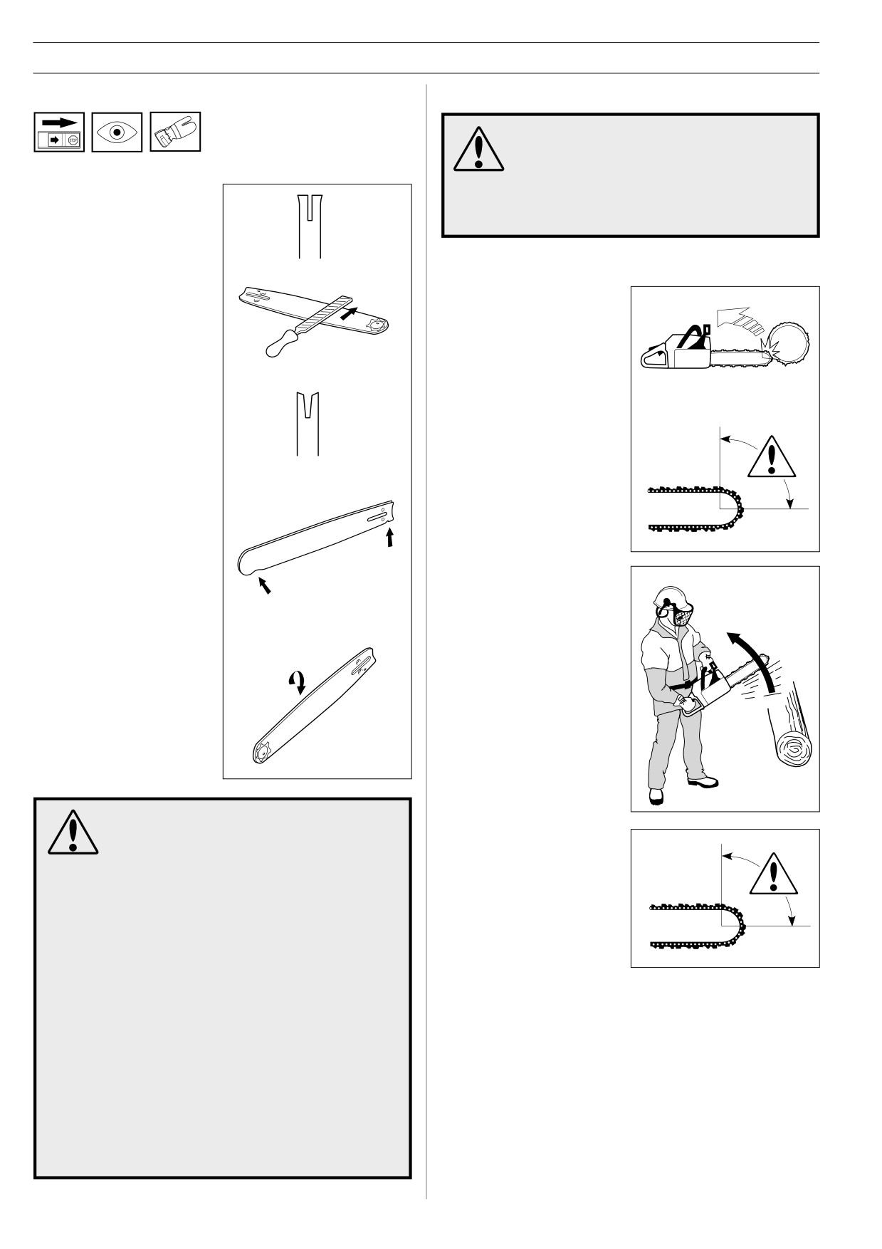
SAFETY INSTRUCTIONS
H Bar
HOW TO AVOID KICKBACK
Kickback can happen very suddenly and
violently; kicking the saw, bar and chain back
at the user. If this happens when the chain is
Check regularly:
moving it can cause very serious, even fatal
injuries. It is vital you understand what causes
kickback and that you can avoid it by taking
• Whether there are burrs on
care and using the right working technique.
the edges of the bar.
Remove these with a file if
necessary.
What is kickback?
The word kickback is used to
describe the sudden reaction
that happens when the upper
quadrant of the tip of the bar
(known as the “kickback zone”)
touches an object and the
• Whether the groove in the
saw is kicked backwards.
bar has become badly worn.
Replace the bar if
necessary.
• Whether the tip of the bar is
uneven or badly worn. If a
hollow forms on one side of
the bar tip this is due to a
slack chain.
Kickback always occurs in
the cutting plane of the saw.
Normally the saw and bar are
thrown backwards and
upwards towards the user.
However the saw may move
in a different direction
• To prolong the life of the bar
depending on the way it was
you should turn it over daily.
being used when the kickback
zone of the bar touched the
object.
MOST CHAIN SAW ACCIDENTS HAPPEN
WHEN THE CHAIN TOUCHES THE OPERA-
TOR.
Kickback only occurs if the
kickback zone of the bar
•
WEAR PERSONAL PROTECTIVE EQUIPMENT
touches an object.
(see the section on ”Chain saw safety
equipment”).
•
DO NOT TACKLE ANY JOB YOU ARE UNSURE OF
(see the section on ”Personal protective
equipment”, ”How to avoid kickback”, ”General
working instructions” and ”Cutting equipment”).
•
AVOID SITUATIONS WHERE THERE IS A RISK OF
KICKBACK (see the section on ”Personal
protective equipment”).
•
USE THE RECOMMENDED PROTECTIVE
EQUIPMENT AND CHECK ITS CONDITION (see
section on ”General working instructions”).
•
CHECK THAT ALL SAFETY FUNCTIONS ARE
WORKING (see section on ”General working
instructions” and ”General safety precautions”).
16 - English
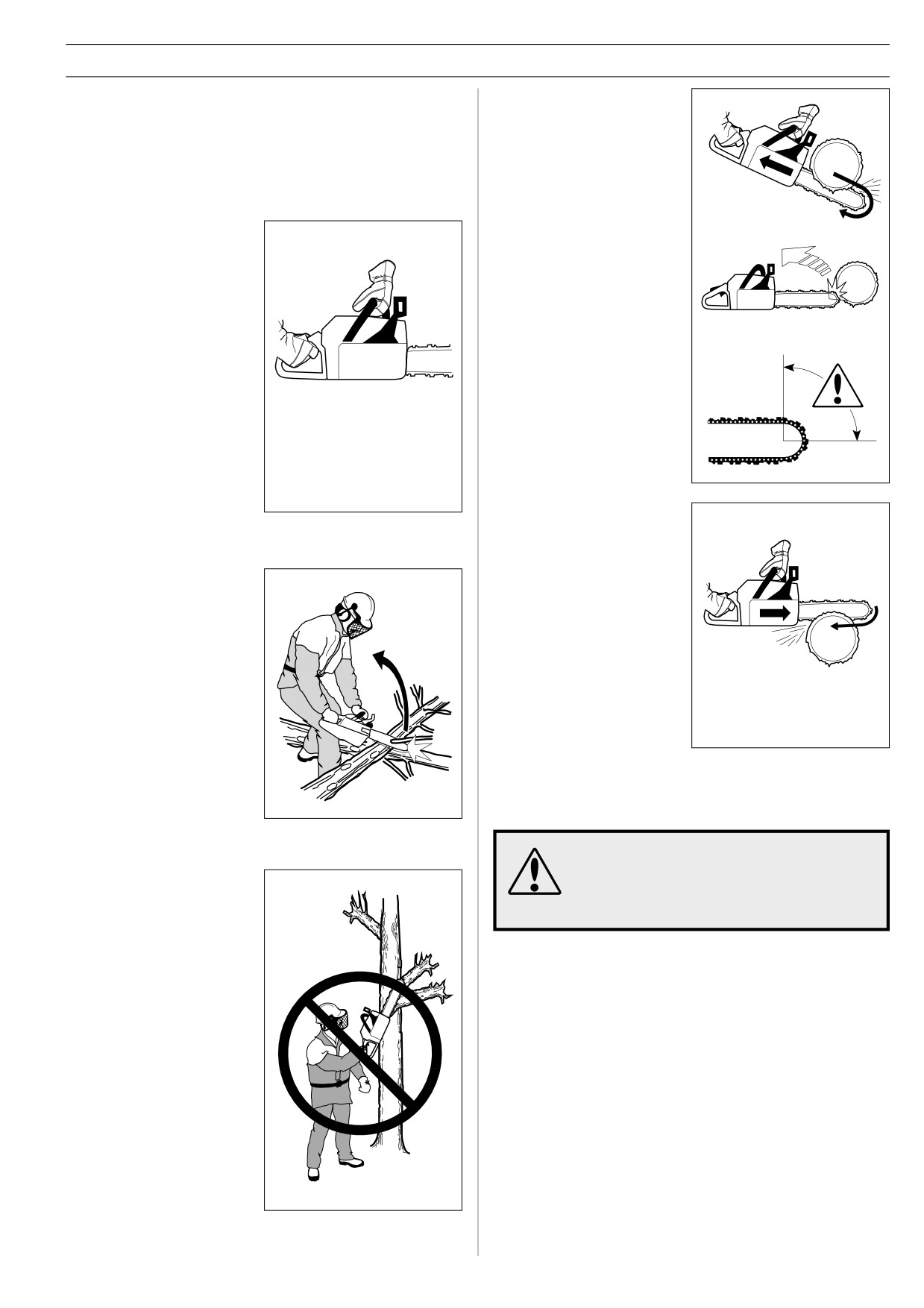
SAFETY INSTRUCTIONS
6
Take great care when you
General rules
cut with the top edge of
1
If you understand what kickback is and how it happens then
the bar, i.e. when cutting
you can reduce or eliminate the element of surprise. By
from the underside of the
being prepared you reduce the risk. Kickback is usually
object. This is known as
quite mild, but it can sometimes be very sudden and
cutting on the push
violent.
stroke. The chain tries to
push the saw back
towards the user.
2
Always hold the saw
firmly with your right hand
Unless the user resists
on the rear handle and
this pushing force there is
your left hand on the front
a risk that the saw will
handle.
move so far backwards
that only the kickback
Wrap your fingers and
zone of the bar is in
thumb around the hand-
contact with the tree. This
les. You should use this
will cause kickback.
grip whether you are
right-handed or left-
Cutting with the bottom
handed. This grip
edge of the bar, i.e. from
minimises the effect of
the top of the object
kickback and lets you
downwards, is known as
keep the saw under
cutting on the pull stroke.
control.
Do not let go of the
handles!
In this case the saw pulls
itself towards the tree and
the front edge of the saw
provides a natural rest
when cutting. Cutting on
3
Most kickback accidents
the pull stroke gives you
happen during limbing.
better control over the
Make sure you are
saw and the position of
standing firmly and that
the kickback zone.
there is nothing in the way
that might make you trip
or lose your balance.
Lack of concentration can
lead to kickback if the
kickback zone of the bar
accidentally touches a
branch, nearby tree or
7
Follow the instructions on sharpening and maintaining your
some other object.
bar and chain. When you replace the bar and chain use
only combinations that are recommended by us. See the
sections on ”Cutting equipment” and ”Technical data”.
The risk of kickback is increased if you use
the wrong cutting equipment or a chain that is
4
Never use the saw above
not sharpened correctly. The wrong
shoulder height and try
combination of bar and chain can increase the
not to cut with the tip of
risk of kickback!
the bar.
Never use the saw one-
handed!
5
Always use a fast cutting speed, i.e. full throttle.
English -
17
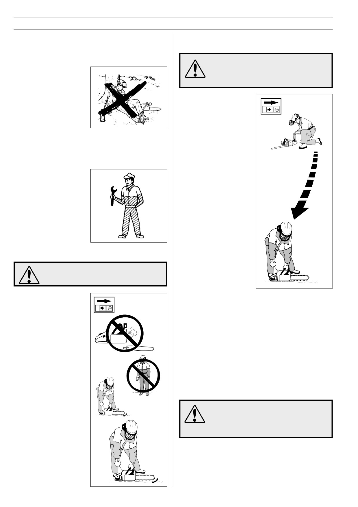
SAFETY INSTRUCTIONS
7
FUEL SAFETY
GENERAL SAFETY PRECAUTIONS
(Refuelling, fuel mixture, storage.)
1
Chain saws are designed solely for cutting wood. The only
cutting equipment that can be used with this chain saw are
the combinations of bars and chains recommended in the
Fuel and fuel vapour are highly inflammable.
”Technical data” section.
Take care when handling fuel and chain oil.
Keep away from naked flames and do not
2
Never use a chain saw if
breathe in fuel vapour.
you are tired, if you have
drunk alcohol, or if you
are taking medication that
affects your vision, your
judgement or your co-
•
Never try to refuel the saw
ordination.
while it is running.
•
Make sure there is plenty of
ventilation when refuelling
3
Always wear suitable protective clothing. See the section
or mixing fuel (2-stroke
on ”Personal protective equipment”.
mixture).
4
Never use a chain saw that has been modified in any way
•
Move the saw at least 3 m
from its original specification.
from the refuelling point
before starting it.
5
Never use a chain saw
Min. 3 m
•
Never start the chainsaw:
that is faulty. Carry out
a) If you have spilt fuel or
(10 ft)
the regular checks,
chain oil on the saw.
maintenance and service
Wipe off the spill and
routines described in this
allow remaining fuel to
manual. Some
evaporate.
maintenance and service
b) If you spill fuel or chain
measures must be carried
oil on yourself or your
out by trained specialists.
clothes. Change your
See the section on
clothes.
”Maintenance”.
c) If there is a fuel leak.
Check regularly for
leaks from the
6
STARTING
FUEL CAP and FUEL
LINES.
Prolonged inhalation of exhaust gases from
the engine, chain lubrication oil mist and/or
saw dust can be unhealthy.
• Never start a chain saw
•
Always store the chain saw and fuel away from any
unless the bar, chain and
sources of sparks or naked flames, e.g. machines, electric
clutch cover are fitted
motors, relays, switches, boilers, etc.
correctly. (See section on
”Assembly”).
•
Always store fuel in an approved container designed for
that purpose.
• Never start a chain saw
indoors. Exhaust fumes can
•
For longer periods of storage or for transport of the saw,
be dangerous.
the fuel and chain oil tanks should be emptied. Ask where
you can dispose of waste fuel and chain oil at your local
petrol station.
•
Before starting the saw
make sure there are no
people or animals nearby
8
Never use any accessories other than those recommended
who might be put at risk.
in this manual. See the sections on ”Cutting equipment”
and ”Technical data”.
•
Place the saw on the
The risk of accident is increased if you use the
ground and hold the rear
wrong cutting equipment or a chain that is not
handle down with your right
sharpened correctly. Using the wrong combi-
foot. Grasp the front handle
nation of bar and chain can increase the risk
firmly using your left hand.
of accidents!
Make sure the chain saw is
steady and the chain is not
touching the ground. Then
grasp the starter handle
with your right hand and pull
the starter cord.
18 - English
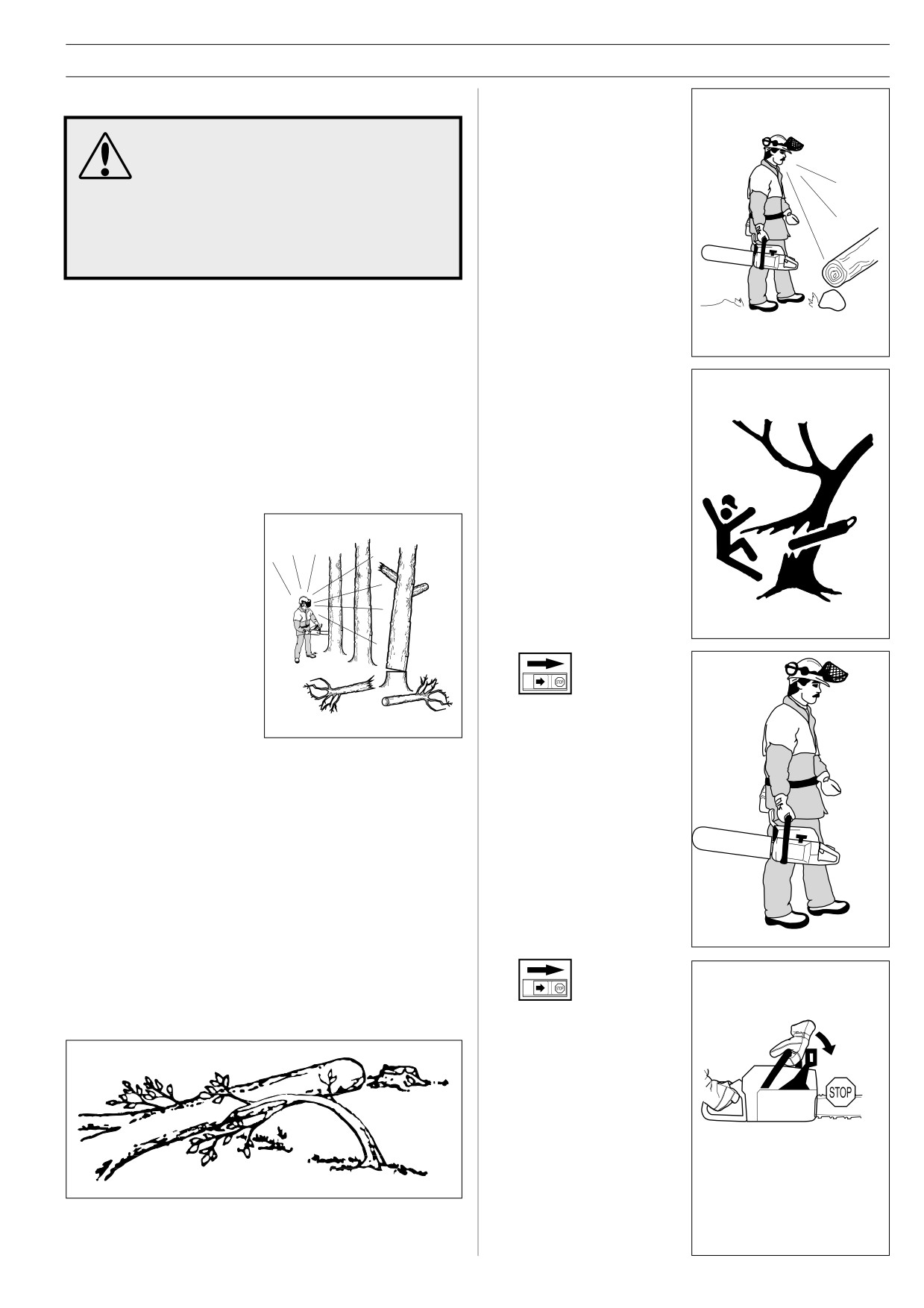
SAFETY INSTRUCTIONS
4
Check the area around
GENERAL WORKING INSTRUCTIONS
you for possible obstacles
such as roots, rocks,
This section describes basic safety rules for
branches, ditches, etc., in
using a chain saw. This information is no
case you have to move
substitute for professional skills and
suddenly. Take great care
experience. If you get into a situation where
when working on sloping
you feel unsafe, stop and seek expert advice
ground.
(look under FORESTRY SERVICES in the
telephone directory).
DO NOT ATTEMPT ANY TASK THAT YOU
FEEL UNSURE OF!
Important
1 Before using a chain saw you must understand the effects of
kickback and what causes it. (See the section on ”How to
avoid kickback”.)
2 Before using a saw you must understand the difference
5
Take the utmost care
between sawing with the top and bottom edges of the bar.
when cutting through
(See the section on ”How to avoid kickback”.)
branches or logs that are
in tension. A log or branch
that is in tension can
1
Basic safety rules
suddenly spring back into
1
Look around you:
its natural position before
or after you cut it. If you
• to make sure there are no
stand on the wrong side
people, animals or other
or start cutting in the
objects nearby that might
wrong place it may strike
affect your work.
you or your chain saw.
This could make you lose
• to make sure that none of
control and cause a
the above might come within
serious accident.
reach of your saw or be
injured by falling trees.
6
Before moving your chain
saw switch off the engine
and lock the chain using
Follow the instructions above, but do not use a chain saw in a
the chain brake. Carry the
situation where you cannot call for help in case of an accident.
saw with the bar and
chain pointing backwards.
Fit a guard to the bar
before carrying the saw
any distance.
2
Do not use the saw in bad weather, such as dense fog,
heavy rain, strong wind, intense cold, etc. Working in cold
weather is tiring and often brings added risks, such as icy
ground, unpredictable felling direction, etc.
3
Take great care when removing small branches and avoid
cutting bushes (i.e. cutting many small branches at the
same time). Small branches can be grabbed by the chain
and thrown back at you, causing serious injury.
7
Never put a chain saw
down while the engine is
running unless you have it
in clear view and the
chain brake is on. Switch
the engine off before
leaving your chain saw for
any length of time.
English -
19
SAFETY INSTRUCTIONS
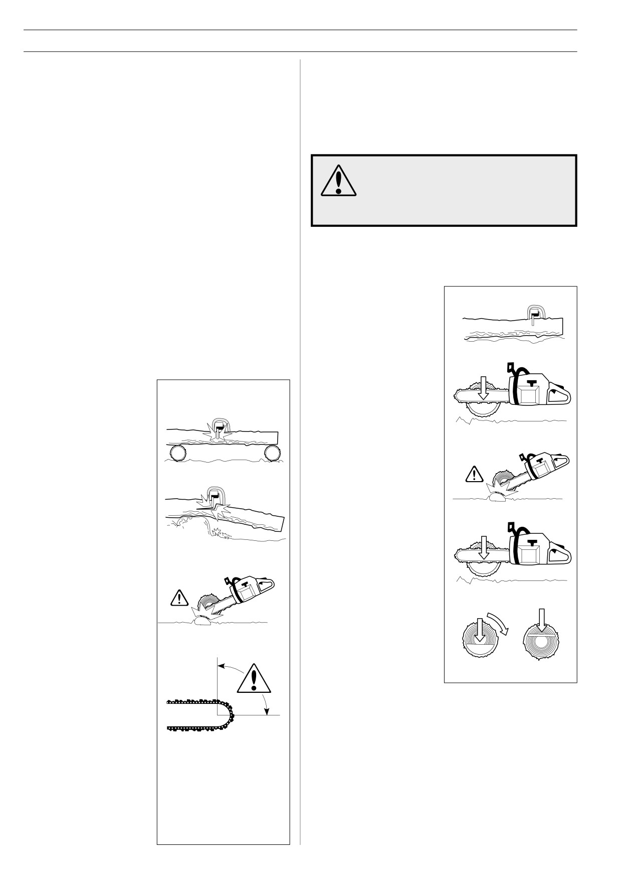
Two factors decide whether the chain will jam or the log will
2
Basic cutting technique
split. The first is how the log is supported and the second is
General
whether it is in tension.
• Always use full throttle when cutting!
In most cases you can avoid these problems by cutting in two
• Reduce the speed to idle after every cut (running the
stages; from the top and from the bottom of the log. You need
engine for too long at full throttle without any load can lead to
to support the log so that it will not trap the chain or split during
serious engine damage).
cutting.
• Cutting from above = Cutting on the pull stroke.
If the chain jams in the cut:
• Cutting from below = Cutting on the push stroke.
STOP THE ENGINE! Don’t try to pull the saw
free. If you do you may damage the chain
See the section on ”How to avoid kickback” to find out why
when the saw suddenly breaks free. Use a
cutting on the push stroke increases the risk of kickback.
lever to open up the cut and free the bar.
Terms:
Cutting
= General term for cutting through wood.
The following instructions describe how to handle most types of
Limbing
= Cutting limbs off a felled tree.
situation that you will be faced with when using a chain saw.
Splitting
= When the object you are cutting breaks off
before the cut is complete.
Cutting
1
The log is lying on the
ground. There is little risk
of the chain jamming or
There are five important factors you should consider
the log splitting. However
before making a cut:
there is a risk that the
chain will touch the
ground when you finish
the cut.
1
Make sure the bar will not
jam in the cut.
Cut all the way through
the log from above. Try
not to touch the ground as
you finish the cut.
2
Make sure the log will not
Maintain full throttle but
split.
be prepared in case the
chain snatches.
A If it is possible to turn
3
Make sure the chain will
the log you should stop
not strike the ground or
cutting about 2/3 of the
any other object during or
way through.
after cutting.
B Turn the log and finish
the cut from the
opposite side.
4
Is there a risk of kick-
back?
5
Do the conditions and
surrounding terrain affect
your safety when
working?
20 - English
SAFETY INSTRUCTIONS
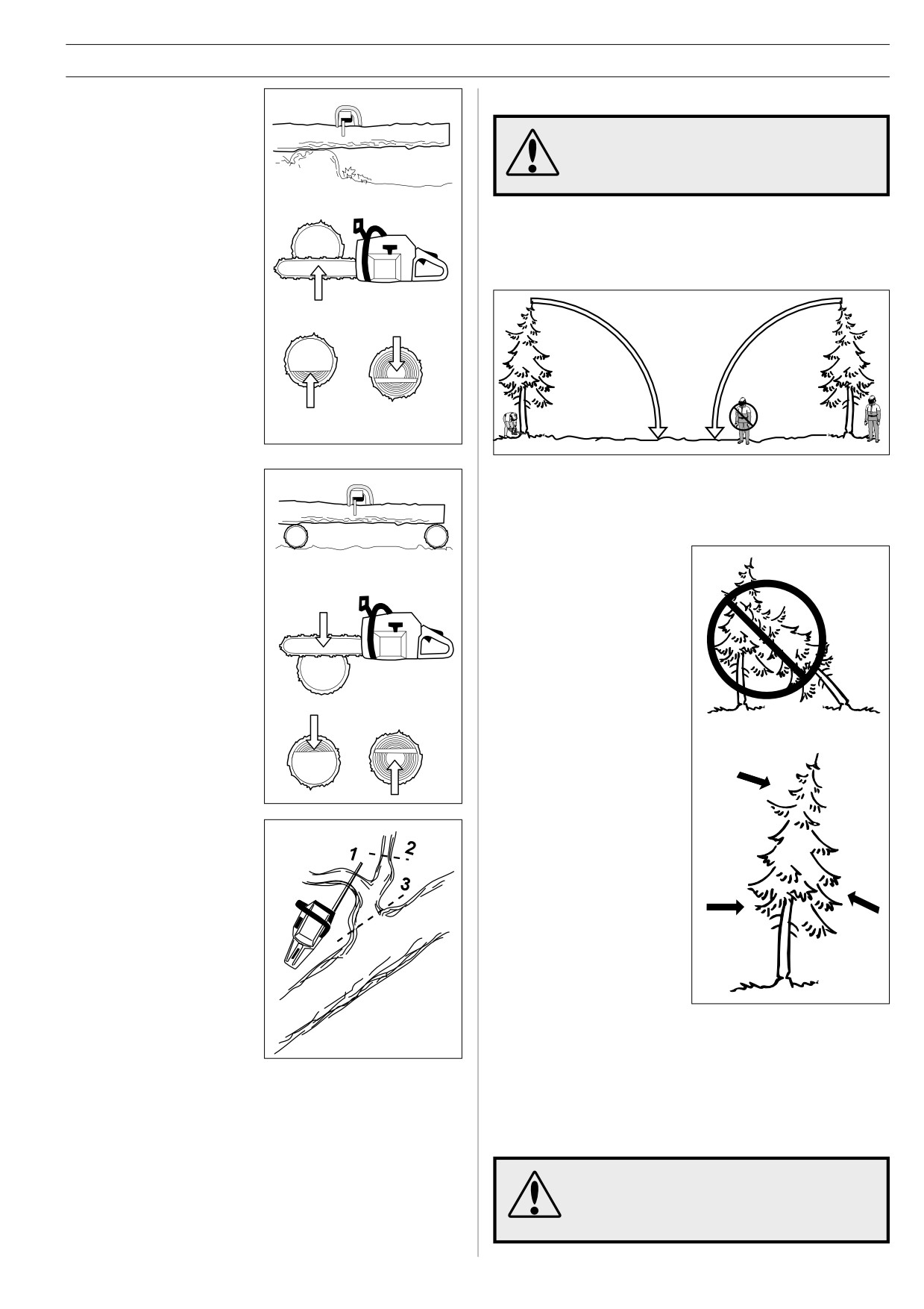
2 The log is supported at one
3
Tree felling technique
end. There is a high risk
that it will split.
It takes a lot of experience to fell a tree.
Inexperienced users of chain saws should not
fell trees. NEVER ATTEMPT A TASK YOU ARE
UNSURE OF.
A Safe distance
A Start by cutting from
The safe distance between a tree that is to be felled and
below (about 1/3 of the
anyone else working nearby is at least 21/2 tree lengths.
way through).
Make sure that no-one else is in this “risk zone” before or during
felling.
B Finish by cutting from
above so that the two
cuts meet.
3 The log is supported at both
B Felling direction
ends. There is a high risk
The aim is to fell the tree in the best possible position for
that the chain will jam.
subsequent limbing and cross-cutting. You want it to fall on
ground where you can move about safely.
The main point to avoid is
letting the tree fall onto
another tree. It can be both
difficult and dangerous to
A Start by cutting from
remove a tree in such a
above (about 1/3 of the
position (see point 4 in this
way through).
section).
Once you have decided which
way you want the tree to fall
you must judge which way the
tree would fall naturally.
B Finish by cutting from
below so that the two
Several factors affect this:
cuts meet.
Lean of the tree
Bend
Limbing
Wind direction
When limbing thick branches
you should use the same
Arrangement of branches
approach as for cutting.
Cut difficult branches piece by
Weight of snow
piece.
You may find you are forced to let the tree fall in its natural
direction because it is impossible or dangerous to try to make it
fall in the direction you first intended.
Another very important factor, which does not affect the felling
direction but does affect your safety, is to make sure the tree
has no damaged or dead branches that might break off and hit
you during felling.
During critical felling operations, hearing
protectors should be lifted immediately when
sawing is completed so that sounds and
warning signals can be heard.
English -
21
SAFETY INSTRUCTIONS
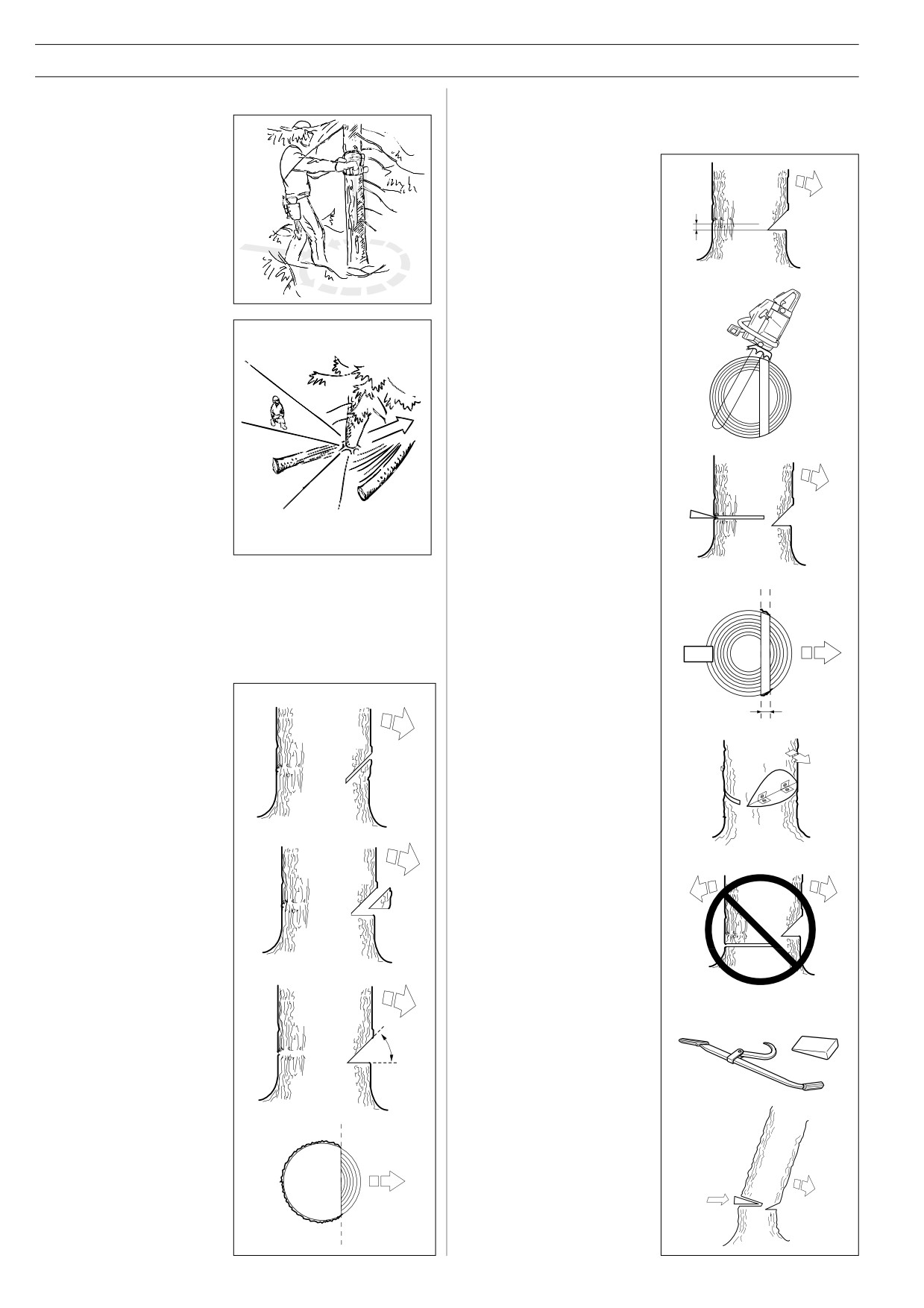
C Clearing the trunk and preparing your retreat
FELLING CUT
The felling cut is made from the opposite side of the tree and it
Remove any branches that
must be perfectly horizontal. Stand on the left side of the tree
are in the way. To do this it is
and cut with the bottom edge of the bar.
best to work from the top
down and keep the trunk
Make the FELLING CUT
between you and the chain
about 3-5 cm (1.5-2 inches)
saw. Never limb above
above the flat section of the
shoulder height.
DIRECTIONAL CUT.
Remove any undergrowth
Set the spike bumper (if one is
from the base of the tree and
fitted) in behind the breaking
check the area for obstacles
strip. Use full throttle and
(stones, branches, holes, etc.)
bring the bar and chain slowly
so that you have a clear path
into the tree. Make sure the
of retreat when the tree starts
tree does not start to move in
to fall. Your path of retreat
the opposite direction to your
should be roughly 135
intended felling direction.
degrees behind the intended
Drive a WEDGE or BREA-
felling direction.
KING BAR into the cut as
soon as it is deep enough.
D Felling
Felling is done using three cuts. First you make the
DIRECTIONAL CUTS, which consist of the TOP CUT and the
Finish the FELLING CUT
BOTTOM CUT; followed by the FELLING CUT. By placing
parallel with the
these cuts correctly you can control the felling direction very
DIRECTIONAL CUT LINE so
accurately.
that the distance between
them is at least at least 1/10
DIRECTIONAL CUT
of the trunk diameter. The
To make the DIRECTIONAL
uncut section of the trunk is
CUT you begin with the TOP
called the BREAKING STRIP.
CUT. Stand to the right of the
tree and cut downwards at an
angle.
The BREAKING STRIP act as
hinges that control the felling
direction of the falling tree.
Next make the BOTTOM CUT
so that it finishes at the end of
the TOP CUT.
All control over the felling
direction is lost if the BREA-
KING STRIP is too narrow or
if the directional cut and felling
cut are badly placed.
The directional cut should run
1/4 of the diameter through
the trunk and the angle
between the TOP CUT and
BOTTOM CUT should be 45°.
When the felling cut and
directional cut are complete
the tree should start to fall
under its own weight or with
the aid of a FELLING WEDGE
The line where the two cuts
or BREAKING BAR.
meet is called the
DIRECTIONAL CUT LINE.
This line should be perfectly
horizontal and at right angles
(90°) to the chosen felling
direction.
22 - English
SAFETY INSTRUCTIONS
We recommend that you use
4
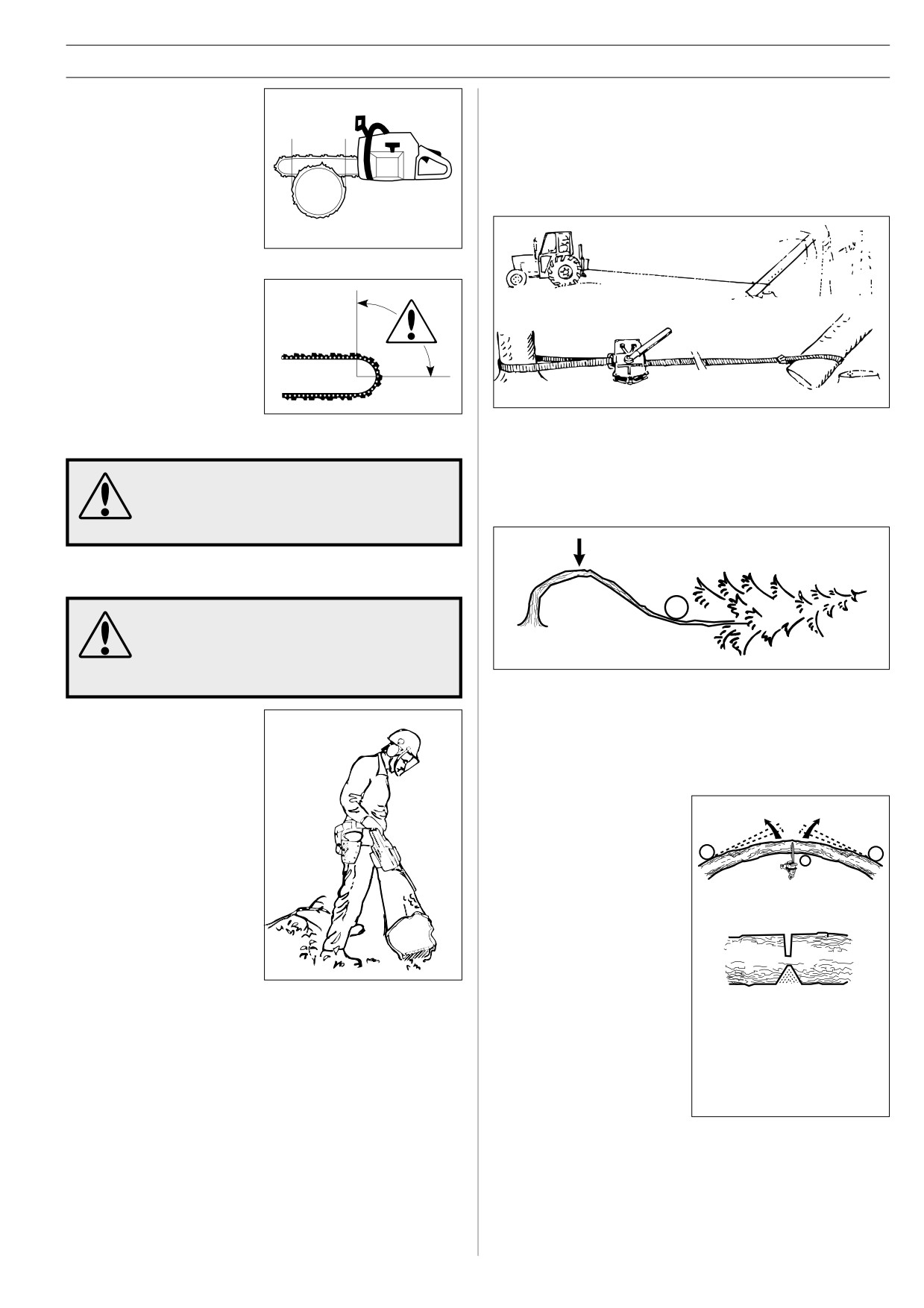
Freeing a tree that has fallen badly = high
a bar that is longer than the
accident risk
diameter of the tree, so that
you can make the FELLING
CUT and DIRECTIONAL CUT
with single cutting stokes.
A Freeing a “Trapped tree”
(See ”Technical data” to find
The safest method is to use a winch.
out which lengths of bar are
A Tractor-mounted
B Portable
recommended for your saw).
There are methods for felling
trees with a diameter larger
than the bar length. However
these methods involve a much
greater risk that the kickback
zone of the bar will come into
contact with the tree.
B Cutting trees and branches that are in tension
Preparations:
UNLESS YOU HAVE SPECIAL TRAINING WE
a) Work out which way the tree or branch will move if released
ADVISE YOU NOT TO FELL TREES WITH A
and where the natural “BREAKING POINT” is (i.e. the place
DIAMETER LARGER THAN THE BAR LENGTH
it would break if it was bent even more).
OF YOUR SAW!
E Limbing
MOST KICKBACK ACCIDENTS HAPPEN
DURING LIMBING!PAY CLOSE ATTENTION
TO THE POSITION OF THE KICKBACK ZONE
OF THE BAR WHEN YOU ARE LIMBING
BRANCHES THAT ARE IN TENSION!
b) Decide which is the SAFEST way to release the tension
Make sure there are no
and whether YOU are able to do it safely. In complicated
obstacles in your way. Work
on the left side of the trunk.
situations the only safe method is to put aside your chain
saw and use a winch.
Work close to the saw for
maximum control. If possible,
General advice:
let the weight of the saw rest
on the trunk.
a) Position yourself so that
you will be clear of the
tree or branch when it
Keep the tree between you
springs free.
and the saw as you move
along the trunk.
b) Make one or more cuts at
or near the BREAKING
POINT. Make as many
cuts of sufficient depth as
F Cutting the trunk into logs
necessary to reduce the
See chapter ”General working instructions” point 2 ”Basic
tension and make the tree
cutting technique”.
or branch break at the
BREAKING POINT.
Never cut straight
through a tree or branch
that is IS in tension!
English -
23
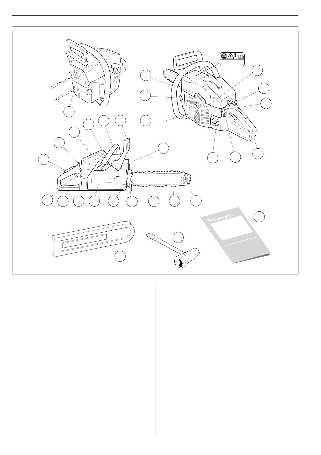
WHAT IS WHAT?
7
6
8
5
10
24
2
3
4
22
1
27
12
9
11
28
21
20
19
28
18
17
16
15
14
13
25
23
26
What is what?
1. Cylinder cover.
15. Saw bar.
2. Front handle.
16. Bumper.
3. Front hand guard.
17. Chain catcher. Catches chain if it jumps or breaks.
4. Starter cover.
18. Clutch cover.
5. Chain oil tank.
19. Right hand guard. Protects right hand if chain breaks or
jumps.
6. Starter handle.
20. Throttle control.
7. Adjuster screw, carburettor.
21. Throttle lock. Prevents accidental operation of throttle
8. Choke control
control.
9. Rear handle.
22. Decompression valve (272XP).
10. Stop switch. Ignition on/off switch.
23. Combination spanner.
11. Fuel tank.
24. Chain tensioning screw.
12. Muffler.
25. Operator's manual.
13. Bar tip sprocket.
26. Bar guard.
14. Saw chain.
27. Start throttle lock.
28. Switch for heated handles (XPG).
24 - English
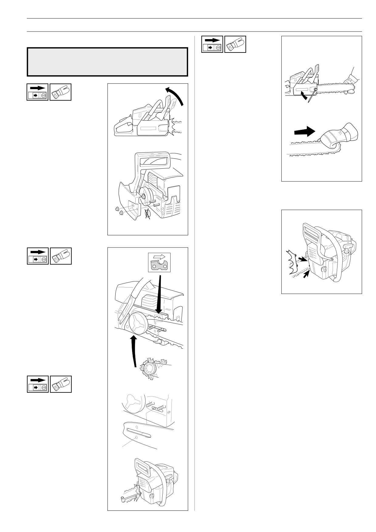
ASSEMBLY
Mounting guide bar and chain
Always wear gloves, when working with the
chain, in order to protect your hands from
Hold up the tip of the bar and
!
injury.
tighten the chain. The chain is
correctly tensioned when
there is no slack on the
underside of the bar, but it can
still be turned easily by hand.
Hold up the bar tip and tighten
the bar nuts with the
Check that the chain brake is
combination wrench.
in disengaged position by
moving the front hand guard
When fitting a new chain, the
towards the front handle.
chain tension has to be
checked frequently until the
chain is run-in. Check the
chain tension regularly. A
correctly tensioned chain
gives good cutting
performance and long lifetime.
Take off the bar nuts and
remove the clutch cover. Take
off the transportation ring (A).
Fitting a spike bumper
To fit a spike bumper -
contact your service agent.
A
Fit the bar over the bar bolts.
Place the bar in its rearmost
position. Place the chain over
the drive sprocket and in the
groove on the bar. Begin on
the top side of the bar. Make
sure that the edges on the
cutting links are facing forward
on the top side of the bar.
Fit the clutch cover and locate
the chain adjuster pin in the
hole on the bar. Check that
the drive links of the chain fit
correctly on the drive sprocket
and that the chain is in the
groove on the bar. Tighten the
bar nuts finger tight.
Tension the chain by using
the combination wrench. Turn
the chain adjuster screw
clockwise. The chain should
be tensioned until it fits snugly
on the underside of the bar.
English -
25
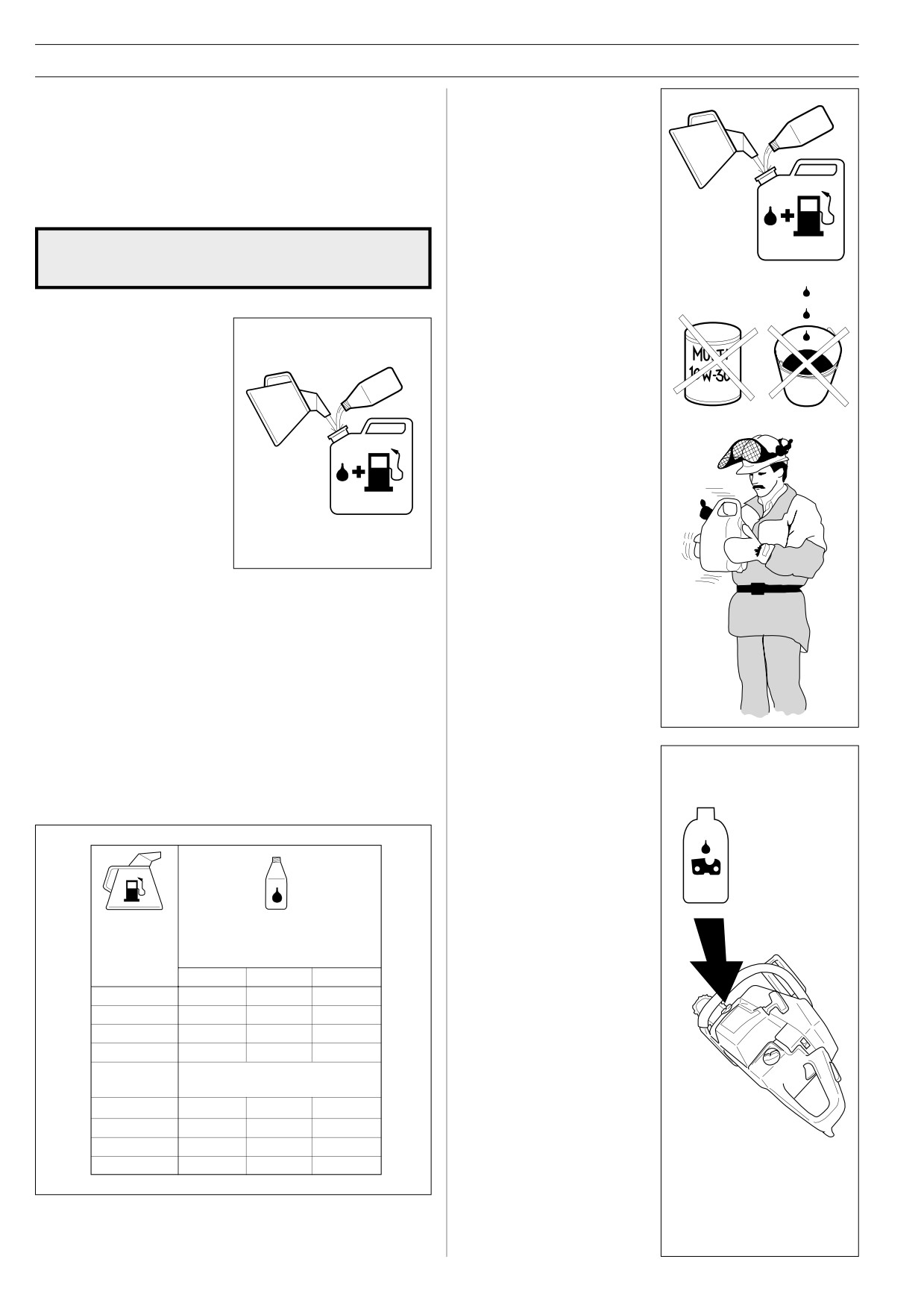
FUEL HANDLING
Fuelmix
Mixing
•
Always mix the petrol and
IMPORTANT! The chain saw is equipped with a two-stroke
oil in a clean container
engine and must always been run using a mixture of petrol and
intended for fuel.
two-stroke engine oil. It is important to accurately measure the
amount of oil to be mixed to ensure that the correct mixture is
•
Always start by filling half
obtained. When mixing small amounts of fuel, even small
the amount of the petrol to
inaccuracies can drastically affect the ratio of the mixture.
be used. Then add the
entire amount of oil. Mix
(shake) the fuel mixture.
Always provide for good ventilation when
Add the remaining amount
handling fuel.
!
of petrol.
•
Mix (shake) the fuel mixture
thoroughly before filling the
Petrol
saw’s fuel tank.
• Use good quality unleaded
or leaded petrol.
•
Do not mix more than max.
• The lowest octane
one month’s supply of fuel.
recommended is 90.
• If you run the engine on a
•
If the saw is not used for
lower octane grade than 90
some time the fuel tank
so-called, knocking can
should be emptied and
occur. This gives rise to a
cleaned.
high engine temperature,
which can result in serious
engine damage.
• When working with
continuous high revs (e.g.
delimbing) a higher octane
grade is recommended.
Two-stroke oil
•
For the best results use HUSQVARNA two-stroke oil, which is
especially developed for chain saws. Mixing ratio 1:50 (2%).
•
If HUSQVARNA two-stroke oil is not available, you may use
another two-stroke oil of good quality that is intended for air
cooled engines. Contact your dealer when selecting an oil.
Mixing ratio 1:33 (3%)-1:25 (4%).
•
Never use two-stroke oil intended for water cooled outboard
Chain oil
motors, so-called, outboard oil.
• The chain lubrication
system is automatic. Always
•
Never use oil intended for four-stroke engines.
use special chain oil with
good adhesive
characteristics.
• In countries where no
special chain oil is available,
EP 90 transmission oil can
be used.
Gasolin
Oil • Öl
Benzin
Huile • Aceite
• Never use waste oil. This
Essence
Lit.
results in damage to the oil
Gasolina
Lit.
2%(1:50)
3%(1:33)
4%(1:25)
pump, the bar and the
chain.
5
0,10
0,15
0,20
10
0,20
0,30
0,40
• It is important to use oil of
15
0,30
0,45
0,60
the right viscosity according
20
0,40
0,60
0,80
to the air temperature.
US
US
gallon
• In temperatures below 0oC
fl. oz.
(32oF) some oils become
2%(1:50)
3%(1:33)
4%(1:25)
too viscous. This can
1
2 1/2
3 3/4
5 1/8
overload the oil pump and
2 1/2
6 1/2
9 3/4
12 7/8
result in damage to the oil
pump components.
5
12 7/8
19 1/4
25 3/4
• Contact your servicing
dealer when choosing chain
oil.
26 - English
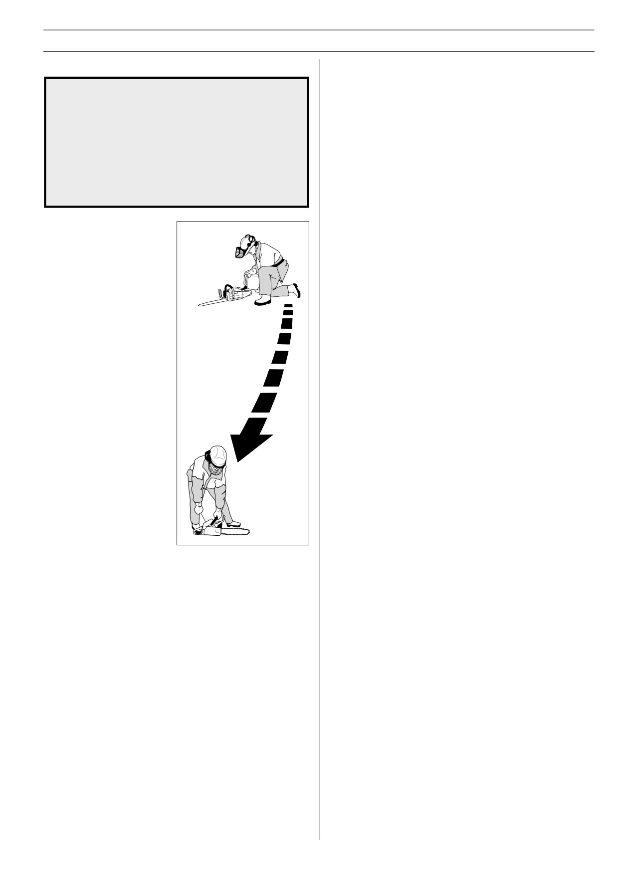
FUEL HANDLING
Fuelling
Taking the following precautions, will lessen
the risk of fire.
!
• Do not smoke or place warm objects in the vicinity of
the fuel.
• Always shut off the engine before refuelling.
• Slowly open the fuel cap, when filling fuel, so that
possible overpressure is slowly released.
• Tighten the fuel cap carefully after fuelling.
• Always move the saw from the fuelling area before
starting.
Clean around the fuel cap.
Clean the fuel and chain oil
tanks regularly. The fuel filter
should be changed at least
once a year. Contamination in
the fuel tanks causes
malfunction. Make sure the
fuel is well mixed by shaking
the container before fuelling.
The volume of chain oil and
fuel tanks are adjusted to
each other. Therefore, always
fill chain oil and fuel at the
Min 3 m
same time.
(10ft)
English -
27
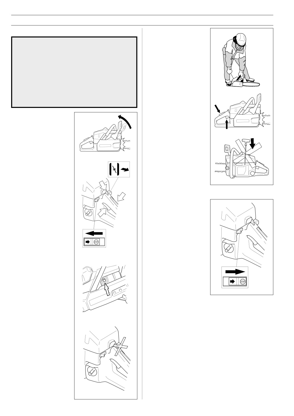
START AND STOP
Start
Start and stop
Grip the front handle with your
left hand and hold the saw
WARNING!
down by putting your right foot
!
in the rear handle. Pull the
starter handle with your right
• Never start the saw engine without the bar, chain and
hand and pull out the starter
clutch cover (chain brake) assembled - or else the
cord slowly until the starter
clutch can come loose and cause personal injuries.
pawls engage. Then pull
• Always move the saw away from the fueling area
sharply.
before starting.
• Place the saw on clear ground and make sure that the
chain is not contacting anything. Also, make sure that
you have a secure footing.
• Keep people and animals well away from the working
Push in the choke control
area.
immediately when the engine
ignites and make repeated
Cold engine
starting attemps. When the
CHAIN BRAKE:
engine starts, rapidly give full
Disengage the chain brake by
throttle. Then the throttle latch
pulling the hand guard
will disengage.
towards the front handle.
IGNITION:
CAUTION! Do not release the
Move the ignition switch to
starter handle from fully pulled
startposition.
out position as this can cause
damage on the saw.
CHOKE:
C
Pull out the choke knob.
A
FAST IDLE:
1.Push down the throttle
Stop
trigger lockout (A).
The engine is stopped by
2.Open the throttle fully (B).
switching off the ignition.
3.Push the throttle latch
(Move the ignition switch to
downwards (C).
B
stopposition.)
(272XP)
If the saw is fitted with a
decompression valve (A):
Press the valve to reduce the
pressure in the cylinder and
make starting easier. Always
use the decompression valve
when starting the saw. Once
A
the saw has started the valve
will automatically return to its
original setting.
Warm engine
Use the same starting
procedure as for a cold
engine, but do not pull out the
choke knob.
28 - English
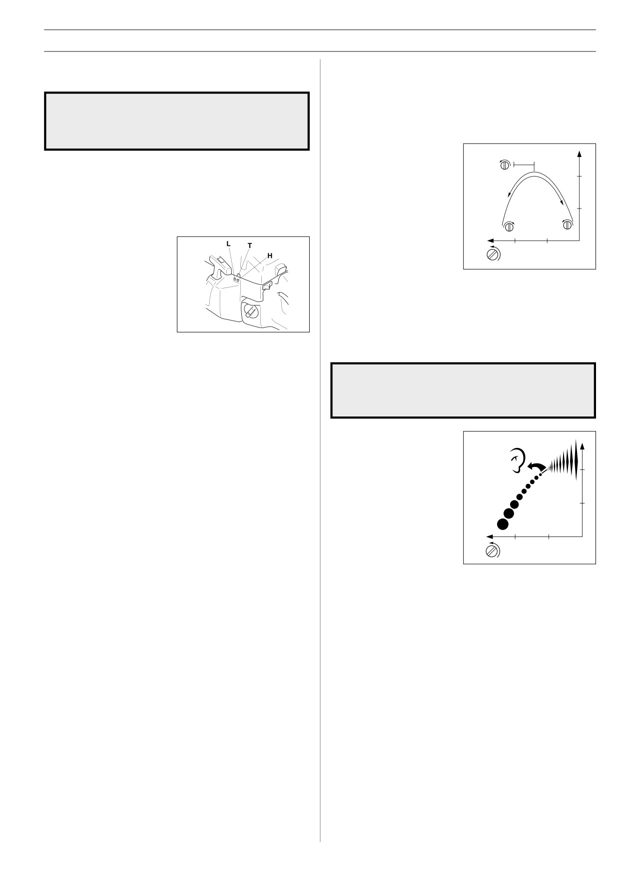
MAINTENANCE
• Now start the saw according to the starting instructions and run it
Carburettor
warm for 10 minutes.
Functioning, Basic setting, Final setting
NOTE! If the chain rotates the T screw should be turned anti-
clockwise until the chain stops.
WARNING! Do not start the saw without the bar,
• Place the saw on a flat surface so that the bar points away from
chain and clutch cover (chain brake) assembled.
you and so that the bar and chain do not come into contact with
!
If you do, the clutch might come loose and
the surface or other objects.
cause severe injuries.
Low speed needle L
Operation
Try to find the highest idling
+ 1/4
speed, turning the low speed
• The carburettor governs the engine speed via the throttle. Air/
needle L clockwise respectively
fuel are mixed in the carburettor. The air/fuel mixture is
counter-clockwise. When the
adjustable. To take advantage of the saw’s maximum output the
highest speed has been found,
setting must be correct.
turn the low speed needle L 1/4
• Adjusting the carburettor means the engine is adapted to local
turn counter-clockwise.
operating conditions, e.g. climate, altitude, petrol and the type of
NOTE! If the chain rotates in
2-stroke oil used.
the idling position, turn the
L
idling speed screw counter-
• The carburettor has three
clockwise until the chain stops.
adjustment possibilities:
L = Low speed jet.
H = High speed jet.
Final setting of the idling speed T
T = Adjustment screw for
Adjust the idling speed with the screw T. If it is necessary to re-
idling.
adjust, first turn the idle speed adjusting screw T clockwise, until
the chain starts to rotate. Then turn, counter-clockwise until the
chain stops. A correctly adjusted idle speed setting occurs when
• The fuel quantity required in relation to the air flow, provided by
the engine runs smoothly in every position. It should also be good
opening the throttle, is adjusted by the L and H-jets. If they are
margin to the rpm when the chain starts to rotate.
screwed clockwise the air/fuel ratio becomes leaner (less fuel)
and if they are turned anti-clockwise the ratio becomes richer
Contact your servicing dealer, if the idle speed
(more fuel). A leaner mixture gives a higher engine speed and a
setting cannot be adjusted so that the chain
richer mixture give a lower engine speed.
!
stops. Do not use the saw until it has been
• The T screw regulates the idling speed. If the screw T is turned
properly adjusted or repaired.
clockwise this gives a higher idling speed; anti-clockwise a lower
idling speed.
High speed needle H
Basic setting and running in
The high speed needle H
The carburettor is adjusted to a basic setting when the saw is
influences the power of the
tested at the factory.
saw. A too lean adjusted high
61:
The basic setting is: H = 1 turns respective
speed needle H (high speed
L = 1 turns.
needle H closed too much)
268:
The basic setting is: H = 1 turns respective
gives overrevs and damages
L = 1 turns.
the engine. Let the saw run at
272XP: The basic setting is: H = 1 turns respective
full speed for about 10 seconds.
L = 1 turns.
Thereafter, turn the high speed
To provide the engine’s components with a good level of
needle H 1/4 turn counter-
H
lubrication (running in) the carburettor should be set for a
clockwise.
richer fuel mixture for the first 3-4 hours of operating. To
Let the saw run again at full
obtain this adjust the overspeed 6-700 rpm under the
speed for about 10 seconds and note the difference of the engine-
recommended max. overspeed.
sound. Repeat this procedure with the high speed needle H turned
If you do not have the possibility to check the overspeed using a
1/4 turn more counter-clockwise. The saw has now been tested
tachometer the H-jet should not be set for a leaner mixture than
with the following settings: H=±0, H=+1/4, H=+1/2 from basic
that stated for the basic setting. The recommended overspeed
adjustment. At full speed the engine has produced a different
should not be exceeded. NOTE! If the chain rotates while idling
sound for each setting. The high speed needle H is correctly set
the T screw should be adjusted anti-clockwise until it stops.
when the saw ”4-cycles” a little. If the saw ”whistles” the setting is
too lean. If there is too much exhaust gas at the same time as the
Fine adjustment
saw ”4-cycles” much, the setting is too rich. Turn the high speed
• When the saw has been ”run-in” the carburettor should be finely
needle H until the setting sounds correct. NOTE! For optimum
adjusted. The fine adjustment should be carried out by
setting of the carburettor, contact a qualified servicing dealer
qualified person. First adjust the L-jet, then the idling screw T
who has a revolution counter at his disposal. The maximum
and then the H-jet.
speed recommended must not be exceeded.
The following engine speed applies:
Max. overspeed
Idling speed
Correctly adjusted carburettor
61:
12.000 rpm
2.500 rpm
268:
12.500 rpm
2.500 rpm
A correctly adjusted carburettor means that the saw accelerates
272XP:
13.500 rpm
2.500 rpm
without hesitation and the saw 4-cycles a little at max speed.
Furthermore, the chain must not rotate at idling. A too lean
Conditions
adjusted low speed needle L may cause starting difficulties and
• Before any adjustments are made the air filter should be clean
bad acceleration.
and the cylinder cowling fitted. Adjusting the carburettor while a
A too lean adjusted high speed needle H gives lower power=less
dirty air filter is in use will result in a leaner mixture when the filter
capacity, bad acceleration and/or damage to the engine.
is finally cleaned. This can give rise to serious engine damage.
A too rich adjustment of the two speed needles L and H gives
• Carefully turn the L and H-jets clockwise to the bottom. Now turn
acceleration problems or too low working speed.
the jets one turn anti-clockwise. The carburettor is now set to H =
1 and L = 1.
English -
29
MAINTENANCE
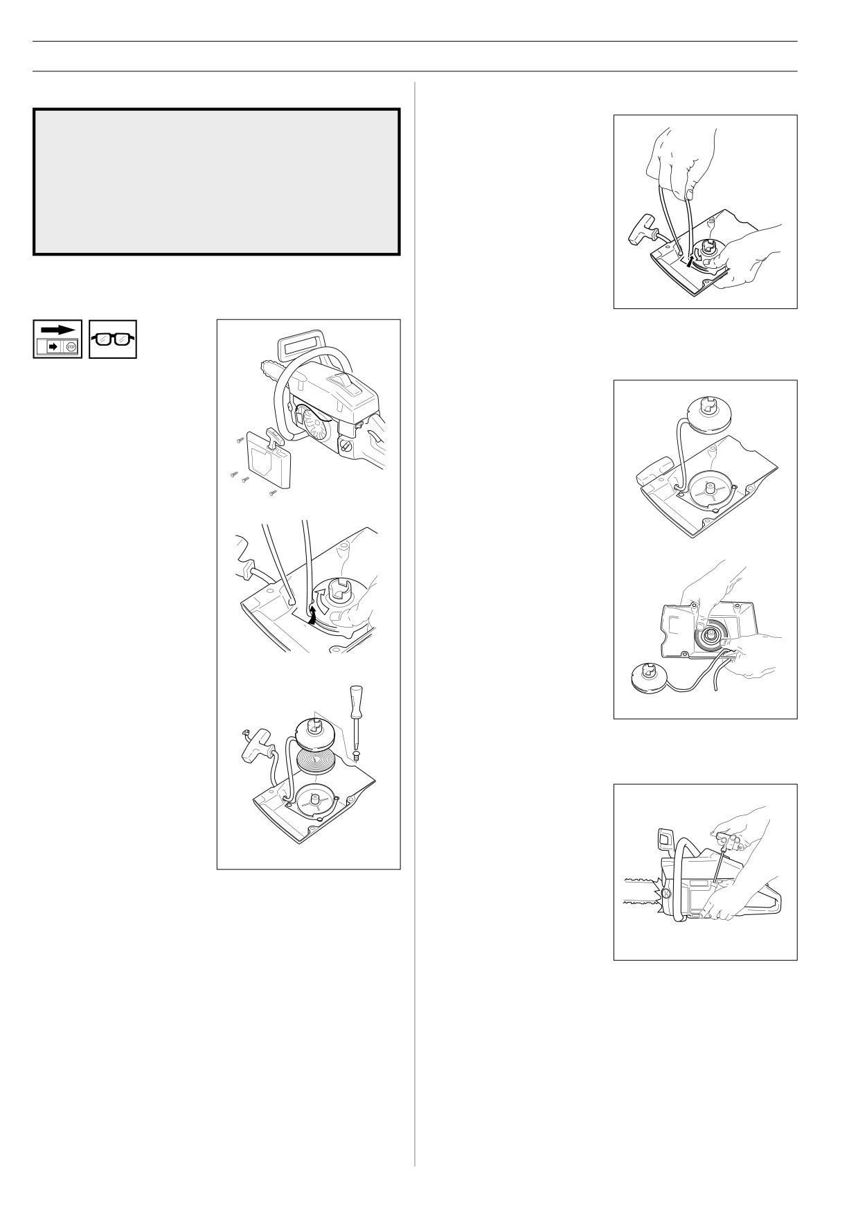
Starter device
Tensioning the recoil spring
WARNING!
• Lift the starter cord up in the
notch on the starter pulley
!
and turn the starter pulley 2
• When the recoil spring is assembled in the starter
turns clockwise.
housing, it is in tensioned position and can when
treated carelessly, pop out and cause injuries.
NOTE! Check that the
• Always be careful, when changing the recoil spring or
starter pulley can be turned
the starter cord. Always wear safety goggles for eye
at least half a turn, when the
protection.
starter cord is entirely pulled
out.
Changing a broken or worn
starter cord
Changing the broken recoil spring
•
Loosen the screws, that
• Lift the starter pulley. (See,
hold the starter device
Changing a broken or worn
against the crankcase and
starter cord). The recoil
remove the starter device.
spring is disassembled from
the starter device, with its
inside facing down. Tap the
starter lightly against a
working bench or similar.
•
Pull out the cord approx. 30
cm and lift it up into the
• Put a new recoil spring in
notch in the pulley. Zero-set
the right position. If the
the recoil spring by letting
spring pops out when
the pulley rotate slowly
assembling, it should be
backwards. Undo the screw
mounted again, out and in
in the centre of the pulley
towards the centre.
and remove the pulley.
• Lubricate the recoil spring
with thin oil. Assemble the
starter pulley, and tension
•
Insert and fasten a new
the recoil spring.
starter cord in the pulley.
Wind approx. 3 turns of the
starter cord on to the pulley.
Assemble the starter pulley
against the recoil spring, so
the end of the spring
engages to the pulley. Fit
Starter device assembly
the screw in the centre of
the pulley. Carry the starter
• Assemble the starter
cord through the hole in the
device, by pulling the starter
starter housing and the
cord out first, then place the
starter handle. Make a knot
starter against the
on the starter cord.
crankcase. Then slowly
release the starter cord so
that the pulley engages with
the pawls.
• Assemble and tighten the
screws, which hold the
starter.
30 - English
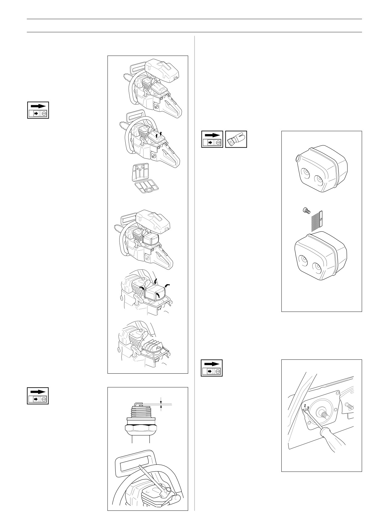
MAINTENANCE
If the spark plug is dirty, clean it and check the electrode gap.
Air filter
Readjust if necessary. The correct gap is 0.5 mm (0.020").
The air filter must be regularly cleaned from dust and dirt in
The spark plug should be replaced after about a month in
order to avoid:
operation or earlier if the electrodes are badly eroded.
• Carburettor malfunctions
61
• Starting problems
IMPORTANT! Always use the recommended spark plug type.
• Engine power reduction
An incorrect spark plug can severely damage the piston/
• Unnecessary wear on
cylinder.
the engine parts
• Abnormal fuel consumption
Clean the air filter daily or
Muffler
more often if the air is
exceptionally dusty in the
working area.
• Disassemble the air filter by
The muffler is designed in
removing the cylinder cover
order to reduce the noise level
and unscrew the filter.
and to direct the exhaust
When reassembling, make
gases away from the operator.
sure that the filter is tight
The exhaust gases are hot
against the filter holder.
and can contain sparks, which
Clean the filter by brushing
may cause fire if directed
or shaking it.
268, 272XP
against dry and combustible
material.
• A more thorough cleaning of
the filter is obtained by
Some mufflers are equipped
washing it in water and
with a special screen. If your
soap.
saw has this type of muffler,
you should clean the screen
An air filter, which is used for
at least once a week. This is
some time, cannot be cleaned
done with a wire brush.
completely. Therefore it must
be replaced by a new one,
CAUTION! The screen must
with regular intervals.
be replaced, if damaged. The
IMPORTANT! A damaged air
saw will be overheated, if the
filter must always be
screen is clogged. This results
replaced.
in damage on the cylinder and
the piston. Never use a saw
with a clogged or defective
muffler.
Adjusting the oil pump
Spark plug
The oil pump can be adjusted
to give four different oil flow
0,5 mm
rates. To adjust the flow rate,
first remove the chain, bar,
clutch cover, centrifugal clutch
The spark plug condition is
and the clutch drum. Using a
influenced by:
screwdriver, adjust the oil flow
• An incorrect carburettor
rate by turning the adjuster
setting.
screw one way or the other.
• Wrong fuel mixture (too
The projection on the screw
much oil in the gasoline).
should point towards the
• A dirty air filter.
chosen setting. The diagram
These factors cause deposits
shows the setting for flow rate
on the spark plug electrodes,
2.
which may result in
malfunction and starting
Recommended settings:
difficulties. If the engine is
13" and 15" bars
Setting 2
low on power, difficult to
18" bars and longer Setting 3-4
start or runs poorly at idling
NOTE! Do not carry out this adjustment with the engine
speed, always check the
running!
spark plug first.
English -
31
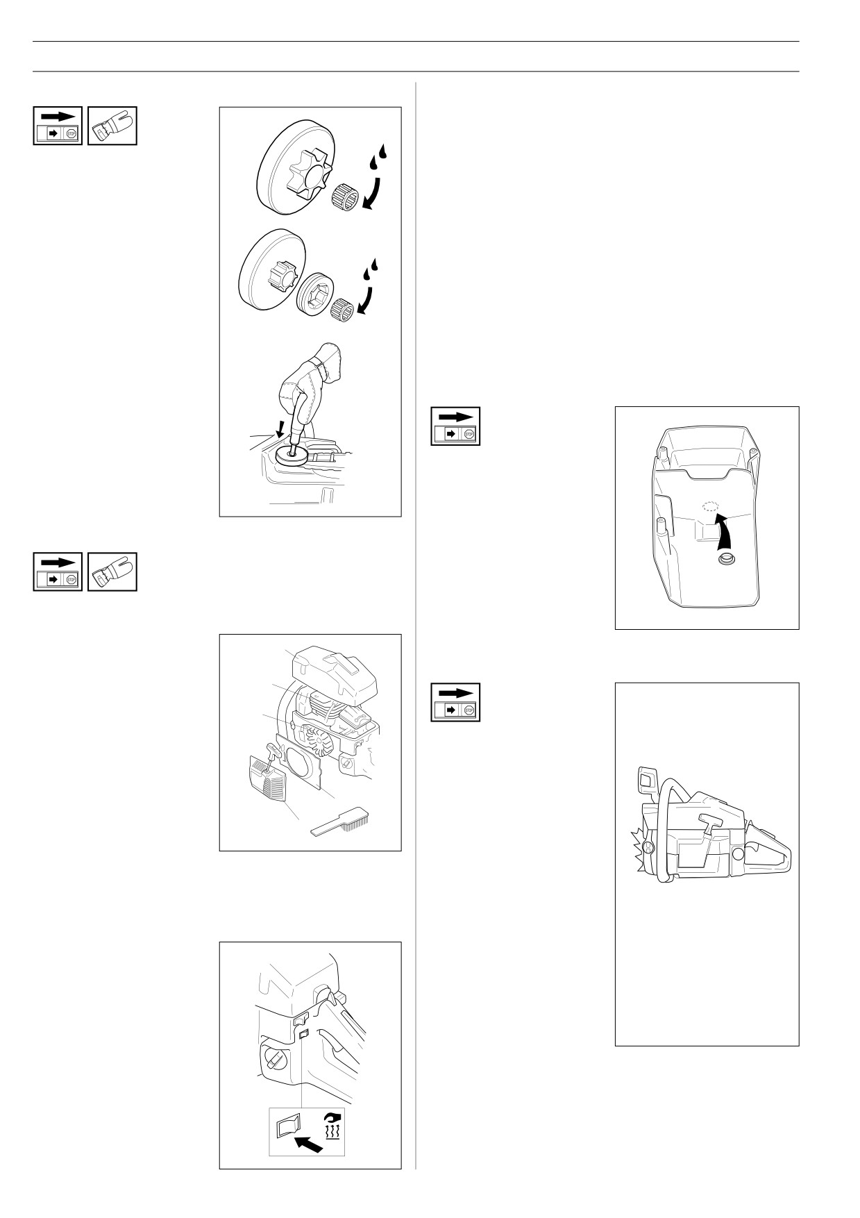
MAINTENANCE
Needle bearing maintenance
Winter use
During winter time, powder snow and cold weather can cause
running problems, such as:
A
• Too low engine temperature.
• Icing on the air filter and carburettor.
The clutch drum is equipped
with one of the following chain
Therefore some special measures are required:
sprockets:
• Partly reduce the air inlet of the starter and by doing that
increase the engine temperature.
• Preheat the intake air to the carburettor by removing the
• Spur sprocket (A) (the chain
special plug between the cylinder and the carburettor space.
sprocket is welded on the
B
drum)
The cylinder cover has a special feature for use in cold
climates. It is possible to open up a hole in the cylinder cover
• Rim sprocket (B)
which can then be plugged with a rubber plug during warmer
(exchangeable)
weather.
(Ref. no. 503 40 59-01)
Both versions have built-in
needle bearing at the drive
Temperature 0oC (32oF) or colder
shaft, whitch has to be
greased regularly (once a
week).
NOTE! Use only high quality
Break out the hole or remove
bearing grease.
the rubber plug so that
preheated air from the
cylinder can enter the
carburettor chamber and
prevent the air filter from icing
Cooling system
up.
To obtain the lowest possible running temperature the saw is
equipped with a cooling system.The cooling system
consists of:
5
1. Air intake on the starter
Temperature -5oC (23oF) or colder
unit.
4
2. Air guide plate.
3
3. Fan blades on the
flywheel.
If the saw is used in severe
cold or powder snow
4. Cooling fins on the
conditions you can fit a
cylinder.
special cover over the starter
2
unit. This reduces the flow of
5. Cylinder cowling
cold air and prevents large
1
(supplies cold air over
amounts of snow from being
the cylinder).
sucked in.
(Ref. no. 503 53 53-71)
Clean the cooling system with a brush once a week, more often
in demanding conditions. A dirty or blocked cooling system
IMPORTANT! If a special
results in the saw overheating which causes damage to
winter kit is assembled or
piston and cylinder.
measures are taken to
increase the engine
temperature, a readjustment
Heated handles
to normal setting has to be
done when the saw is used
(272XPG)
under normal conditions.
On the model 272XPG both
Otherwise, there is a risk of
the front handle and the rear
overheating, which can
handle are equipped with
cause severe engine
electrical heating coils. These
damage.
are supplied with electricity
both from a built-in generator
IMPORTANT! Any maintenance other than that described in
in the electrical system. The
this manual must be carried out by your servicing dealer.
switch for the heating coils is
placed below the stop switch.
When the red marking is
visible, the heating is on.
32 - English
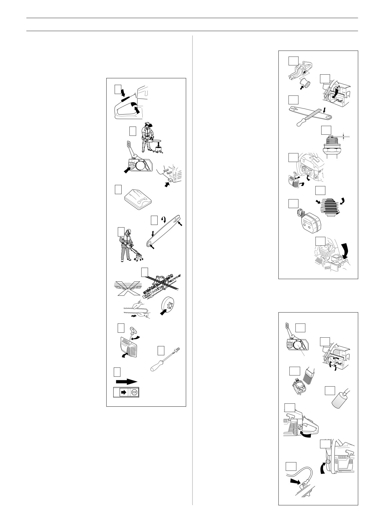
MAINTENANCE
Below you will find some general maintenance instructions.
Weekly maintenance
If you have more questions, contact your servicing dealer.
1.
Check that the AV
elements are not soft or
1
Daily maintenance
torn.
2.
Lubricate the clutch drum
1.
Check that all the
2
bearing.
components of the throttle
1
control operate safely (i.e.
3.
File off burrs, if any, on
throttle lock, throttle lever
3
the sides of the bar.
and start throttle lock).
4.
Clean the spark plug and
2.
Clean the chain brake
check the gap.
and check its function
The correct gap is 0,5 mm
according to the
4
0,5 mm
2
(0.020 inch).
instructions. Make sure
that the chain catcher is
5.
Check the starter and the
undamaged. Otherwise
recoil spring. Clean the
replace it immediately.
fins on the flywheel.
5
3.
Clean or replace the air
filter as necessary. Check
for damage or holes.
6.
Clean the cooling fins on
the cylinder.
4.
The bar should be turned
3
6
daily for more even wear.
7.
Clean or change the
Check the lubrication hole
screen in the muffler.
7
in the bar, to be sure it is
not clogged. Clean the
bar groove, if the bar has
4
a sprocket tip, this should
8.
Clean the carburettor
5
body and air box.
be lubricated.
8
5.
Check the function of the
oiler to be sure the bar
and chain receive proper
lubrication.
6
6.
Sharpen the chain and
check its tension and
condition. Check the drive
sprocket for wear.
Replace if necessary.
Monthly maintenance
7.
Check the starter and
1. Check the brake band on
starter cord for wear or
the chain brake for wear.
damage. Clean the air
7
1
intake slots on the starter
2. Check the clutch centre,
housing.
clutch drum and clutch
2
spring for wear.
8.
Check for any loose nuts
8
and screws and retighten
3. Clean the outside of the
if necessary.
carburettor.
9.
Test the stop switch to be
9
3
sure it shuts off the
engine.
4. Check the fuel filter.
Change if necessary.
4
5
5. Flush the inside off the
fuel tank with gasoline.
6. Flush the inside of the oil
6
tank with gasoline.
7
7. Check all cables and
connections.
English -
33
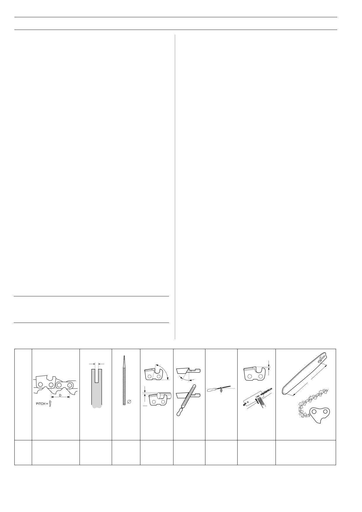
TECHNICAL DATA
61
268
61
268
Engine
Noise levels
Cylinder volume, cu.in/cm3
3,8/61,5
4,1/67
Equivalent (see note 1) noise
Cylinder bore, inch/mm
1,9/48
2,0/50
pressure level at operator’s
Stroke, inch/mm
1,3/34
1,3/34
ear, measured according to
Idle speed, rpm
2.500
2.500
relevant international
Recommended max.
standards, dB(A).
101
102
speed, unloaded, rpm
12.000
12.500
Equivalent (see note) noise
Power, kW/ rpm
2,9/8.300
3,2/9.000
power level, measured
according to relevant interna-
Ignition system
tional standards, dB(A).
110
112
Manufacture
Electrolux
Electrolux
Type of ignition system
ET
ET
Vibration levels
Spark plug
Champion
Champion
(See note 2)
RCJ 7Y
RCJ 7Y
Front handle m/s2
4,7
4,4
Electrode gap, inch/mm
0.020/0,5
0.020/0,5
Rear handle m/s2
7,6
6,1
Fuel and lubrication
Chain/bar
system
Standard bar length,
Manufacturer
Tillotson
Tillotson
inches/cm
15"/38
15"/38
Carburettor type
HS 254
HS 260
Recommended bar lengths,
Fuel capacity, US pint/litre
1.6/0,75
1.6/0,75
inches/cm
15"/38-20"/51
15"/38-20"/51
Oil pump capacity at 8500 rpm,
Usable cutting length,
ml/min
3-6-9-12
3-6-9-12
inches/cm
14"/36-19"/48
14"/36-19"/48
Oil capacity, US pint/litre
0,95/0,45
0,95/0,45
Type of oil pump
Automatic
Automatic
Chain speed at max.
power, m/sec
18,4
20,0
Weight
Pitch, inches
3/8"
3/8"
Without bar and chain, Lbs/kg
13,4/6,1
13,7/6,2
Thickness of drive link, inch/mm
0.058"/1,5
0.058"/1,5
Number of teeth on drive
sprocket
7
7
Note 1: Equivalent noise level is, according to ISO 7182 and
Bar and chain combinations
ISO 9207, calculated as the time-weighted energy total for
The following combinations are CE approved.
noise levels under various working conditions with the following
time distribution: 1/3 idle, 1/3 max. load, 1/3 max. speed.
Bar
Chain
Length, Pitch,
Max.
Note 2: Equivalent vibration level is, according to ISO 7505,
inches
inches
tip radius
calculated as the time-weighted energy total for vibration levels
under various working conditions with the following time
15
3/8
11T
Husqvarna H42
distribution: 1/3 idle, 1/3 max. load, 1/3 max. speed.
16
3/8
11T
Husqvarna H42
18
3/8
11T
Husqvarna H42
20
3/8
11T
Husqvarna H42
L
1
5
Type
Inch
Inch/mm
Inch/mm
Angle
Angle
Angle
Inch/mm
Inch/cm: dl
H42
3/8"
0.058"/1,5
7/32" /5,5
60°
25°
10°
0.025"/0,65
15"/38:56 16"/41:60
18"/46:68 20"/51:72
34 - English

TECHNICAL DATA
272XP
272XP
Engine
Noise levels
Cylinder volume, cu.in/cm3
4,4/72,2
Equivalent (see note 1) noise
Cylinder bore, inch/mm
2,05/52
pressure level at operator’s
Stroke, inch/mm
1,3/34
ear, measured according to
Idle speed, rpm
2.500
relevant international
Recommended max.
standards, dB(A).
101
speed, unloaded, rpm
13.500
Equivalent (see note) noise
Power, kW/ rpm
3,6/9.300
power level, measured
according to relevant interna-
Ignition system
tional standards, dB(A).
110
Manufacture
Electrolux
Type of ignition system
ET
Vibration levels
Spark plug
Champion
(See note 2)
RCJ 7Y
Front handle m/s2
3,2
Electrode gap, inch/mm
0.020/0,5
Rear handle m/s2
3,9
Fuel and lubrication
Chain/bar
system
Standard bar length,
Manufacturer
Tillotson
inches/cm
15"/38
Carburettor type
HS 260
Recommended bar lengths,
Fuel capacity, US pint/litre
1.6/0,75
inches/cm
15"/38-20"/51
Oil pump capacity at 8500 rpm,
Usable cutting length,
ml/min
3-6-9-12
inches/cm
14"/36-19"/48
Oil capacity, US pint/litre
0,95/0,45
Type of oil pump
Automatic
Chain speed at max.
power, m/sec
20,7
Weight
Pitch, inches
3/8"
Without bar and chain, Lbs/kg
13,9/6,3
Thickness of drive link, inch/mm
0.058"/1,5
XPG: 14,3/6,5
Number of teeth on drive
sprocket
7
Note 1: Equivalent noise level is, according to ISO 7182 and
Bar and chain combinations
ISO 9207, calculated as the time-weighted energy total for
The following combinations are CE approved.
noise levels under various working conditions with the following
time distribution: 1/3 idle, 1/3 max. load, 1/3 max. speed.
Bar
Chain
Length, Pitch,
Max.
Note 2: Equivalent vibration level is, according to ISO 7505,
inches
inches
tip radius
calculated as the time-weighted energy total for vibration levels
under various working conditions with the following time
15
3/8
11T
Husqvarna H42
distribution: 1/3 idle, 1/3 max. load, 1/3 max. speed.
16
3/8
11T
Husqvarna H42
18
3/8
11T
Husqvarna H42
20
3/8
11T
Husqvarna H42
L
1
5
Type
Inch
Inch/mm
Inch/mm
Angle
Angle
Angle
Inch/mm
Inch/cm: dl
H42
3/8"
0.058"/1,5
7/32" /5,5
60°
25°
10°
0.025"/0,65
15"/38:56 16"/41:60
18"/46:68 20"/51:72
English -
35
TECHNICAL DATA
EU declaration of conformity (Only applies to Europe)
(Directive 89/392/EEC, Annex II, A)
We, Husqvarna AB, S-561 82 Huskvarna, Sweden, tel: +46-36-146500, declare under sole responsibility that the
chain saws Husqvarna 61, 268 and 272XP/XPG from 1997’s serial numbers and onwards (the year is clearly stated
in plain text on the type plate with subsequent serial number), are in conformity with the following standards or other
normative documents following the provisions in the COUNCIL’S DIRECTIVES:
- of June 14 1989 “relating to machinery” 89/392/EEC and applicable supplements.
- of May 3 1989 “relating to electromagnetic compatibility” 89/336/EEC, and applicable supplements.
The following harmonised standards have been applied: EN292-2, EN608.
The supplied chain saw conforms with the example that underwent EU type approval.
Registered body: 0363, Deutsche Prüfstelle, Weißensteinstraße 70/72, 34131 Kassel, Germany, has carried out EU
type approval in accordance with article 8 section 2c. The EU type approval certificates, in accordance with Annex VI,
are numbered: K-EG222 - 61, K-EG 221 - 268, K-EG220 - 272XP/XPG.
Huskvarna October 21, 1997
Bo Andréasson, Development manager
36 - English
´*33^¶6\¨
´*33^¶6\¨
2001W08