HUSQVARNA R 316TX, R 316TX AWD, R 316TsX AWD. Operator's manual
R 316TX, R 316TX AWD, R 316TsX AWD
ES
Manual de usuario
2-39
PT
Manual do utilizador
40-77
EN
Operator's manual
78-112
IT
Manuale dell'operatore
113-149
Contents
Introduction
78
Transportation, storage and disposal
106
Safety
84
Technical data
109
Assembly
88
Service
111
Operation
90
Warranty
111
Maintenance
94
EC Declaration of Conformity
112
Troubleshooting
104
Registered trademarks
112
Introduction
Pre-delivery inspection and product
numbers
Note: A pre-delivery inspection has been done of this
product. Make sure that you receive a signed copy of
the pre-delivery inspection document from your dealer.
Service agent contact informa-
tion:
This operator’s manual belongs to product with product number / serial number:
/
Engine:
Transmission:
optional accessory to use the product for other tasks.
Product description
Speak to your Husqvarna dealer for more information
The product is a ride-on lawn mower. Forward and
about which accessories that are available.
reverse pedals let the operator adjust the speed
seamlessly. An hour meter shows how many hours the
Insure your product
operator has used the product. The product has
Make sure that you have insurance coverage for your
headlights and is used with Combi cutting decks with
new product. Speak to your insurance company if you
BioClip. Models R 316TX AWD and R 316TsX AWD
are not sure. We recommend a fully comprehensive
have all wheel drive (AWD).
insurance that includes third party, fire, damage, theft
and liability.
Intended use
The product is made to cut grass on open and level
ground in residential areas and gardens. Attach an
78
844 - 002 -
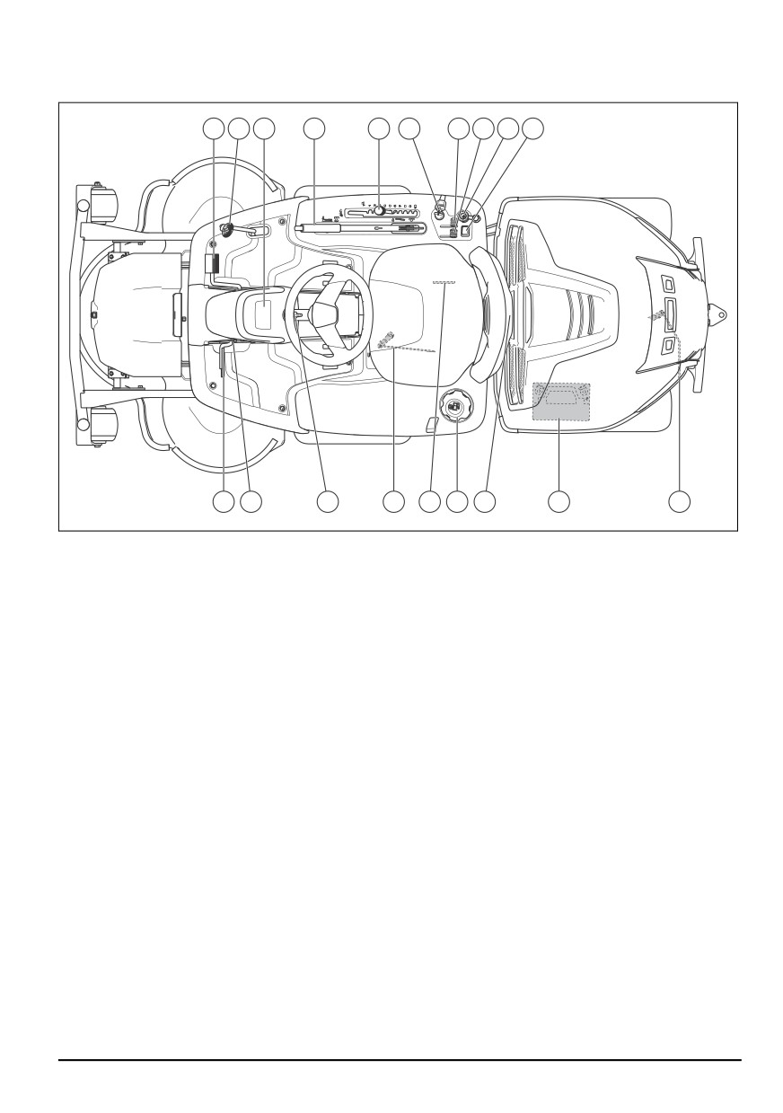
Product overview
1
2
3
4
5
6
7
8
9
10
19
18
17
16
15
14
13
12
11
1. Forward pedal
12. Battery
2. Rearward pedal
13. Cover lock
3. Display
14. Fuel tank cap
4. Lift lever for the cutting deck
15. Type plate with a scannable code
5. Cutting height lever
16. Lever to engage or disengage the transmission on
6. Ignition lock / Headlight switch
the front axle on AWD products.
7. Throttle control
17. Steering wheel adjustment
8. Choke control
18. Lock button for parking brake
9.
12 V power outlet
19. Parking brake pedal
10. Switch for high beam light
11. Lever to engage or disengage the transmission on
the rear axle.
844 - 002 -
79
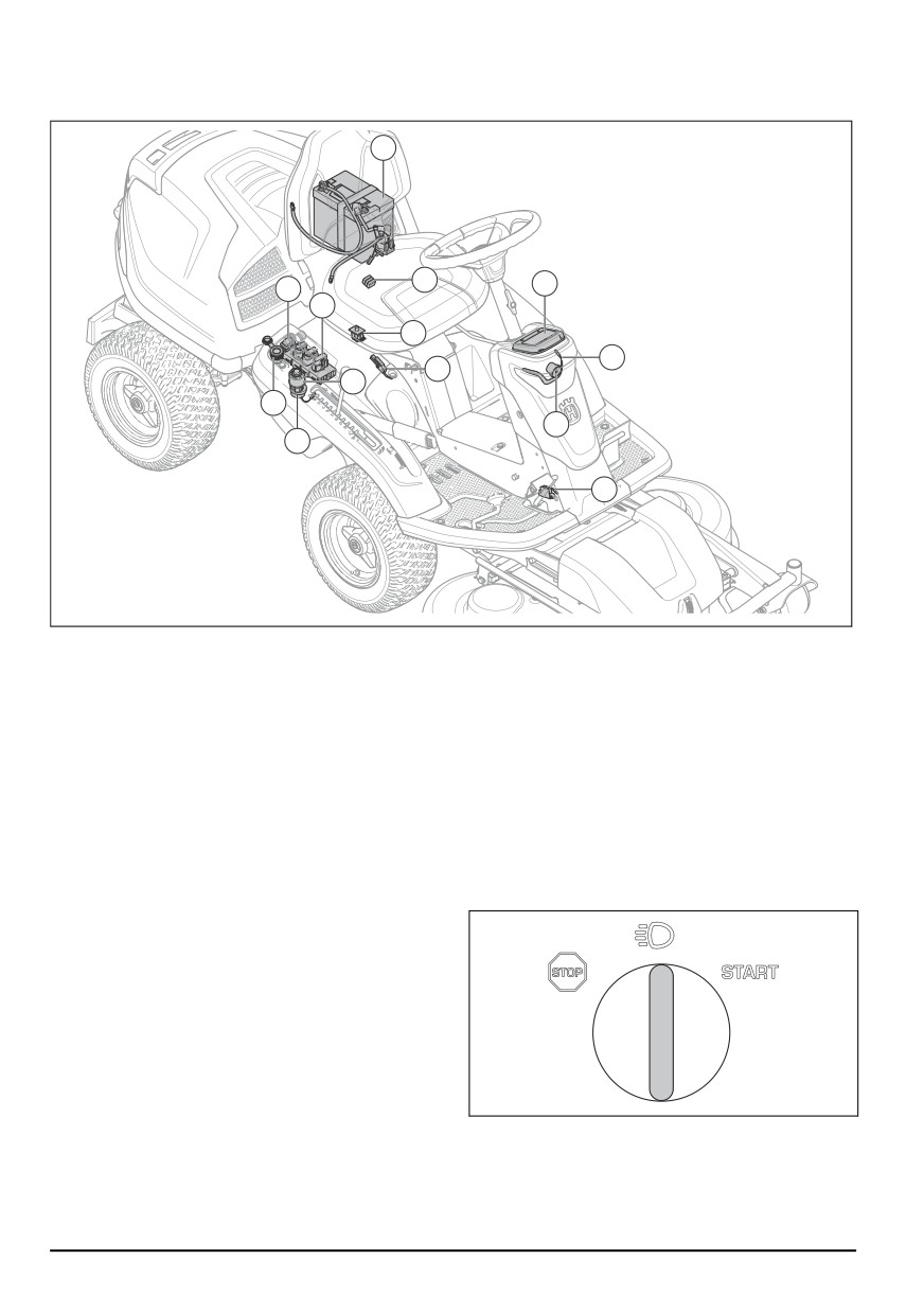
Electrical system overview
1
2
3
11
10
8
4
7
9
12
5
13
6
1. Battery
your mobile device. The Husqvarna Connect app gives
2. Main fuse
extended functions for your Husqvarna product:
3. Display
•
Lock and unlock function to prevent not approved
4. Work lamp
operation of the product.
5. High beam light
•
Extended product information.
6. Microswitch, parking brake
•
Information about, and help with, product parts and
7. Microswitch for the lift lever
servicing.
8. Operator presence control (OPC)
Headlights
9. Ignition lock / Headlight switch
10. Mower Control Module
The headlights have work lights and high beam lights.
Turn the ignition key to the lights position to make the
11. High beam switch
work light come on. The work lights stay on for 3
12. 12 V power outlet
minutes after the engine stops.
13. Buzzer
Mower control module
The product has a mower control module that gives the
operator information about the product. The information
shows on the display on the instrument panel. Refer to
Display on page 82.
The mower control module enables the servicing dealer
to connect to the product when they do servicing.
Husqvarna Connect
The product has wireless technology and can connect to
mobile devices that have the Husqvarna Connect app
installed. The Husqvarna Connect app is a free app for
80
844 - 002 -
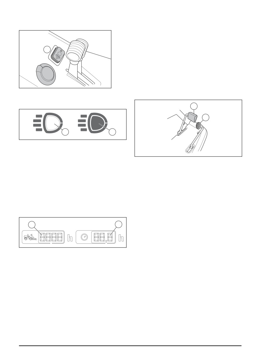
Push the switch (A) to make the high beam lights come
The time with ignition on but engine off, is not registered.
on or go off.
The last digit shows tenth of an hour (6 minutes).
Operator presence control (OPC)
The OPC engages when the operator lifts from the seat.
A
The engine and the drive to the blades stop if the blades
are engaged or the parking brake is not applied. Refer to
Start conditions on page 86.
Forward and rearward pedals
The speed is gradually adjusted with 2 pedals. The left
pedal (1) is used to move forward, and the right pedal
(2) is used to move rearward. The product brakes when
When the work lights are on, the headlight symbol (B)
the pedals are released.
shows on the display. When the high beam lights are on,
the filled headlight symbol (C) shows on the display.
1
2
B
C
Power outlet
The voltage of the power outlet is 12 V. The power outlet
has a fuse, see Technical data on page 109.
Cutting deck
Set the power outlet to on and off with the power switch
found on the control panel.
The cutting decks for this product are Combi cutting
decks with BioClip. BioClip cuts the grass into fertilizer.
Hour meter
The Combi cutting decks can also be used without
BioClip. Without BioClip the grass is ejected to the rear.
The product has 2 hour meters on the display. The hour
meters show how many hours of operation of the engine
has in total (A) and during the operation period (B). A
new operation period starts if the engine is off at a
minimum of 6 h.
A
B
844 - 002 -
81
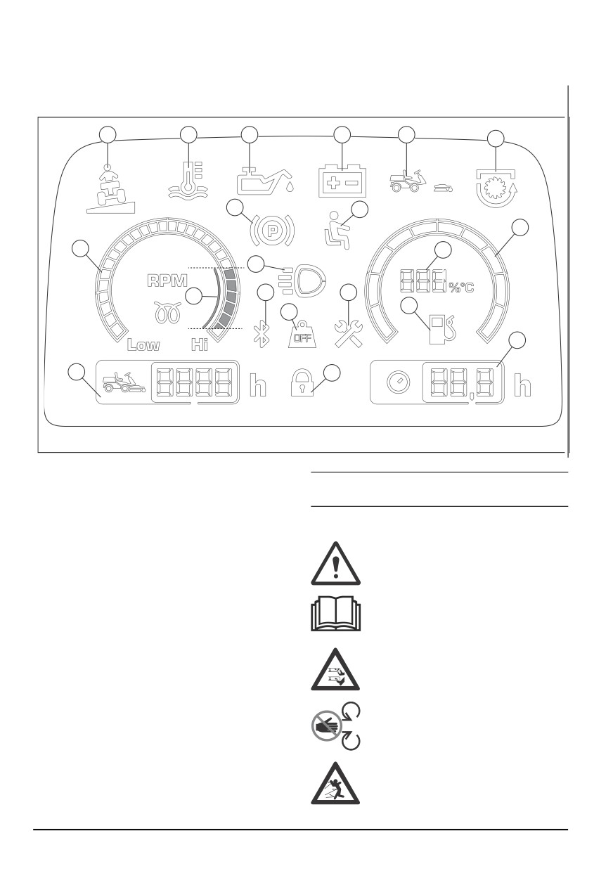
Display
The display on the instrument panel shows information of the status of the product.
1
2
3
4
5
6
9
10
11
7
16
12
8
13
15
17
14
20
18
19
1. Slope indicator
Note: The look of the display can be different between
2. Hydraulic temperature indicator
different models.
3. Oil pressure indicator
4. Battery level indicator
Symbols on the product
5. Indicator for cutting deck presence
6. PTO indicator
WARNING: Careless or incorrect use can
7. Tachometer
result in serious injury or death to the
8. Recommended engine RPM when you operate the
operator or others.
product.
9. Parking brake indicator
Read the operator's manual carefully and
10. Operator presence control (OPC)
make sure that you understand the
instructions before use.
11. Fuel gauge
12. Work light or high beam light indicator
13. Bluetooth®
Rotating blades. Keep body parts away from
14. Weight Transfer
the cover when the engine is on.
15. Service indicator
16. Fuel gauge measured in steps of 5%
17. Low fuel level indicator
Warning: rotating parts. Keep body parts
18. Total run time
away.
19. Digital lock
20. Operation run time
Look out for ejecting objects and ricochets.
82
844 - 002 -
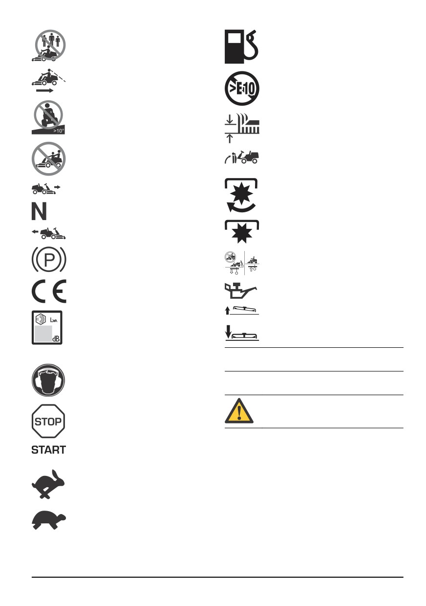
Never use the product if persons, especially
children, or animals, are in the vicinity.
Fuel.
Look behind you before and while you move
the product in reverse.
Max. ethanol 10%.
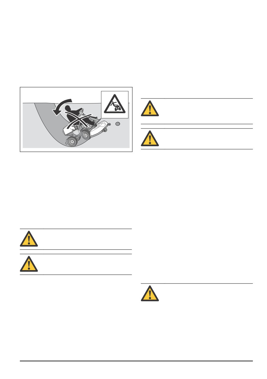
Never cut grass across a slope. Do not cut
grass on ground that slopes more than 10°.
See To cut grass on slopes on page 86.
Cutting height.
Servicing position for the cutting height
Never carry passengers on the product or
lever.
equipment.
Move forward.
The blades are engaged.
Neutral gear.
Move rearward.
The blades are disengaged.
Parking brake.
Engage and disengage the drive system.
This product is in accordance with
Oil level.
applicable EC directives.
Servicing position for the cutting deck.
Noise emission to the environment
according to the European Community's
Directive. The product's emission is
Operation position for the cutting deck.
specified in the Technical data chapter and
on the label.
Note: Other symbols/decals on the product refer to
certification requirements for some commercial areas.
EU V
Always use approved hearing protection.
WARNING: Tampering with the engine
voids the EU type-approval of this product.
Stop the engine.
Product liability
Start the engine.
As referred to in the product liability laws, we are not
liable for damages that our product causes if:
•
the product is incorrectly repaired.
•
the product is repaired with parts that are not from
Engine speed - fast.
the manufacturer or not approved by the
manufacturer.
•
the product has an accessory that is not from the
Engine speed - slow.
manufacturer or not approved by the manufacturer.
•
the product is not repaired at an approved service
center or by an approved authority.
844 - 002 -
83
Safety
Safety definitions
•
Learn to recognize the safety decals.
•
Keep the product clean to make sure that you can
Warnings, cautions and notes are used to point out
clearly read signs and stickers.
specially important parts of the manual.
•
Keep in mind that the operator will be held
responsible for accidents that involve other persons
WARNING: Used if there is a risk of injury or
or their property.
death for the operator or bystanders if the
•
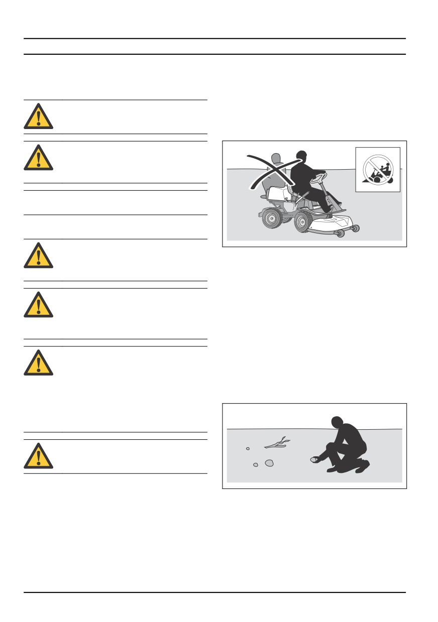
Do not transport passengers. The product must only
instructions in the manual are not obeyed.
be used by one person.
CAUTION: Used if there is a risk of damage
to the product, other materials or the
adjacent area if the instructions in the
manual are not obeyed.
Note: Used to give more information that is necessary in
a given situation.
General safety instructions
WARNING: This product can cut off hands
and feet and throw objects. Serious injury or
•
Do not let the product stay unsupervised with the
death may occur if you do not obey the
engine on. Always stop the blades, apply the parking
safety instructions.
brake, stop the engine and remove the ignition key
before you let the product stay unsupervised.
•
Only use the product in daylight or in other well-lit
WARNING: Do not continue to use a
conditions. Keep the product at a safe distance from
product with damaged cutting equipment.
holes or other irregularities in the ground. Look out
Damaged cutting equipment can throw
for other possible risks.
objects and cause serious injury or death.
Replace damaged blades immediately.
•
Do not use the product in bad weather, for example
in fog, in rain, moist or in wet locations, strong winds,
intense cold, risk of lightning, etc.
WARNING: This product produces an
•
Find and mark stones and other fixed objects to
electromagnetic field during operation. This
prevent collision.
field may under some circumstances
•
Clear the area of objects such as stones, toys, wires,
interfere with active or passive medical
etc. that may become caught in the blades and be
implants. To reduce the risk of serious or
thrown out.
fatal injury we recommend persons with
medical implants to consult their physician
and the medical implant manufacturer
before operating this product.
WARNING: Read the warning instructions
that follow before you use the product.
•
Always be careful and use your common sense.
Avoid all situations which you consider to be beyond
•
Do not let children or other persons not approved for
your capability. If you feel uncertainty about the
operation of the product to use or do servicing on it.
operating procedures after you read the operator's
Local laws may regulate the age of the user.
manual, consult an expert before you continue.
•
Make sure that nobody else is in the vicinity of the
•
Read and understand the operator's manual and the
product when you start the engine, engage the drive
instructions on the product carefully before you start
or start to move the product.
the product.
•
Keep an eye on the traffic when you mow near a
•
Learn how to use the product and its controls safely
road or move across a road.
and learn how to stop the product quickly.
84
844 - 002 -
•
Do not use the product if you are fatigued, while
•
Always look down and behind you before and while
under the influence of alcohol or drugs, medicine or
you move in reverse. Look out for large and small
anything that can have a negative effect on your
obstacles.
vision, alertness, coordination or judgement.
•
Decrease the speed before you turn around a
•
Always park the product on a level surface with the
corner.
engine stopped.
•
Stop the blades when you move across areas that
you do not cut.
Safety instructions regarding children
CAUTION: Read the caution instructions
WARNING: Read the warning instructions
that follow before you use the product.
that follow before you use the product.
•
Before you operate the product, clear the cold air
•
Serious accidents can occur if you are not on your
intake of the engine from grass and dirt. If the cold
guard for children in the vicinity of the product.
air intake is blocked, there is a risk of engine
Children can be attracted to the product and to
damage.
mowing. It is very possible that children do not stay
•
Move around stones and other larger objects
where you last saw them.
carefully and make sure that the blades do not hit
•
Keep children away from the area to be mowed.
the objects.
Make sure that an adult is responsible for the
•
Do not operate the product across objects. Stop and
children.
examine the product and cutting deck if you operate
•
Keep an eye out and stop the product if children
the product across or into an object. If it is
enter the work area. Be very careful near corners,
necessary, make repairs before you restart.
bushes, trees or other objects that prevents a clear
view.
Personal protective equipment
•
Before and while you move the product in reverse,
look behind you and look down to make sure there
are no small children in the vicinity of the product.
WARNING: Read the warning instructions
•
Do not let children ride along. They can fall off and
that follow before you use the product.
get seriously injured or prevent safe maneuvering of
the product.
•
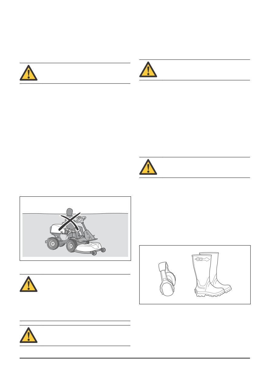
Use approved personal protective equipment when
•
Do not let children operate the product.
you use the product. Personal protective equipment
cannot fully prevent injury but it decreases the
degree of injury if an accident does occur. Let your
dealer help you select the right equipment.
•
Always wear approved hearing protection. Long term
exposure to noise can result in permanent hearing
impairment.
•
Always wear protective shoes or protective boots.
Steel toes are recommended. Do not use the
product barefoot.
Safety instructions for operation
WARNING: Do not touch the engine or
exhaust system during or directly after
operation. The engine and the exhaust
system become very hot during operation.
Risk of burn injuries, fire and damage to
property or adjacent areas. When you
operate the product, keep away from bushes
•
Wear gloves when necessary, for example when you
and other objects.
attach, examine or clean the cutting equipment.
•
Do not wear loose-fitting clothing, jewelry or other
items that can get caught in moving parts.
•
Keep first aid equipment and fire extinguisher close
WARNING: Read the warning instructions
at hand.
that follow before you use the product.
844 - 002 -
85
Safety devices on the product
Muffler
The muffler keeps the noise levels to a minimum and
sends the exhaust fumes away from the operator.
WARNING: Read the warning instructions
that follow before you use the product.
Do not use the product if the muffler is missing or
defective. A defective muffler increases the noise level
and the risk of fire.
•
Do not use a product with defective safety devices.
Do a check of the safety devices regularly. If the
WARNING: The muffler becomes very hot
safety devices are defective, speak to your
during and after use and when the engine
Husqvarna service agent.
operates at idle speed. Be careful near
•
Do not make modifications on safety devices. Do not
flammable materials and/or fumes to prevent
use the product if protective plates, protective
fire.
covers, safety switches or other protective devices
are not attached or are defective.
To do a check of the muffler
To do a check of the ignition lock
•
Examine the muffler regularly to make sure that it is
attached correctly and not damaged.
•
Start and stop the engine to do a check of the
ignition lock. See To start the engine on page 91
Protective covers
and To stop the engine on page 93.
•
Make sure that the engine starts when you turn the
Missing or damaged protective covers increase the risk
ignition key to START.
of injury on moving parts and hot surfaces. Do a check
of the protective covers before you operate the product.
•
Make sure that the engine stops immediately when
Make sure that the protective covers are correctly
you turn the ignition key to STOP.
attached and do not have cracks or other damages.
Replace damaged covers.
Start conditions
These conditions are necessary to start the engine:
To cut grass on slopes
•
The cutting deck is lifted and the parking brake is
applied.
WARNING: Read the warning instructions
The engine must stop in these situations:
that follow before you use the product.
•
The cutting deck is lowered and the operator lifts
•
To cut grass on slopes increases the risk that you
from the seat.
can not control the product and that it overturns. This
•
The cutting deck is lifted, the parking brake is not
can cause injury or death. It is necessary to cut the
applied and the operator lifts from the seat.
grass carefully on all slopes. If you cannot reverse
Try to start the engine without one of the conditions.
up a slope or if you do not feel safe, do not cut it.
Change the conditions and try again. Do this check
•
Remove stones, branches and other obstacles.
daily.
•
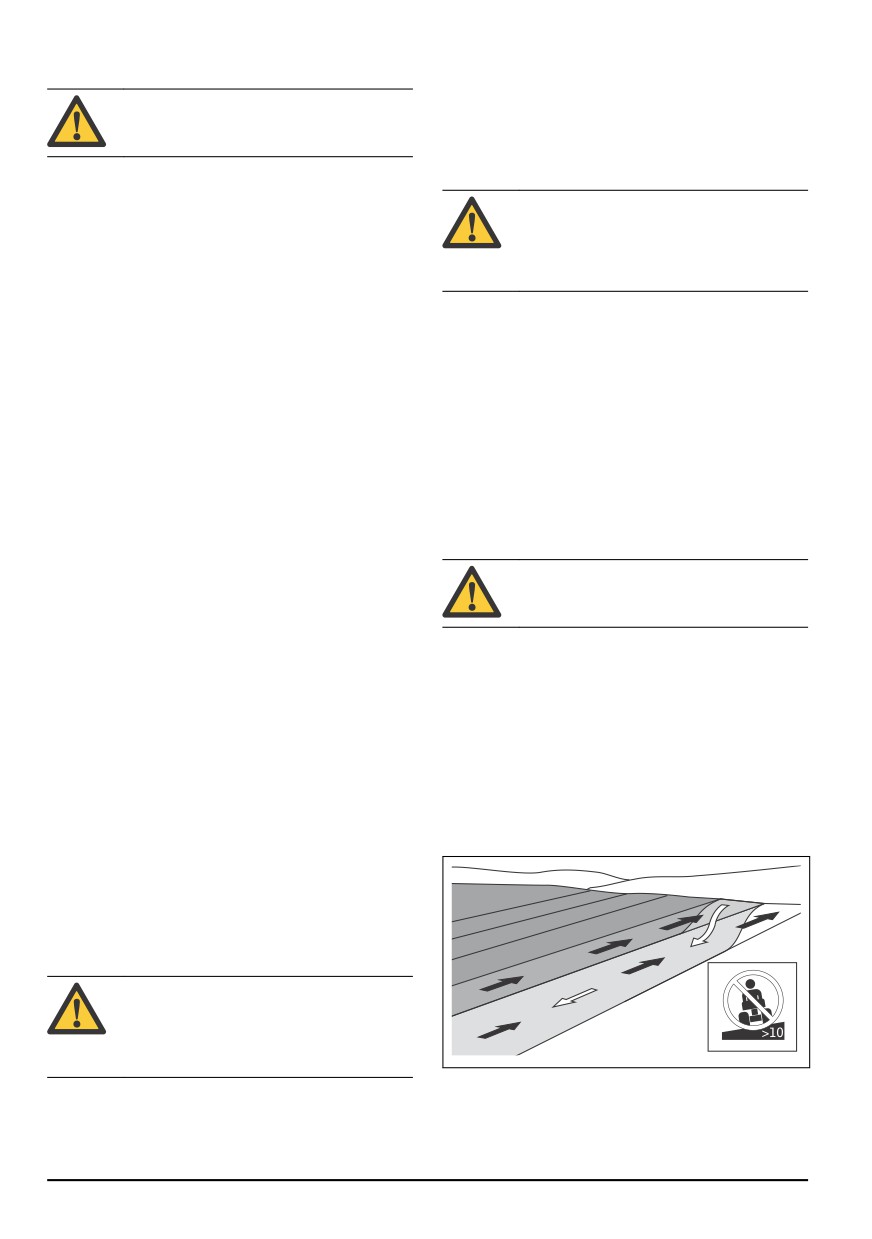
Cut up and down the slope, not from side to side.
•
Do not move down a slope with the cutting deck
To do a check of the speed limiter
lifted.
•
Release the forward pedal to brake.
•
Do not operate the product on ground that slopes
more than 10°.
•
For more brake power, press the reverse pedal.
•
Make sure that the forward and reverse pedals are
not blocked and can be operated freely.
•
Make sure that the product brakes when the forward
pedal is released.
Parking brake
WARNING: If the parking brake does not
work, the product can start to move and
cause injury or damage. Make sure that the
parking brake is regularly examined and
adjusted.
•
Do not start or stop on a slope.
See To do a check of the parking brake on page 97.
•
Move smoothly and slowly on slopes.
•
Do not make sudden changes in speed or direction.
86
844 - 002 -
•
Do not turn more than necessary. Turn slowly and
•
Do not fill above recommended fuel level. The heat
gradually when you move down a slope. Move at low
from the engine and the sun makes the fuel expand
speed. Turn the wheel carefully.
and the fuel overflows if the tank is filled too much.
•
Look out for and do not move across furrows, holes
•
Do not fill too much. If you spill fuel on the product,
and bumps. There is a higher risk that the product
clean up the spill and wait until it is dry before you
overturns on ground that is not flat. Long grass can
start the engine. If you spill on your clothing, change
hide obstacles.
it.
•
Do not cut grass near edges, ditches or banks. The
•
Store fuel in approved containers only.
product can suddenly overturn if a wheel moves
•
Store the product and fuel in such a way that there is
across the edge of a steep slope or a ditch, or if an
no risk that fuel leaks or fumes can cause damage.
edge gives way. If the product falls into water, there
•
Drain off the fuel in an approved container outdoors
is a risk of drowning.
and away from naked flames.
Battery safety
WARNING: A damaged battery can cause
an explosion and cause injury. If the battery
has a deformation or is damaged, speak to
an approved Husqvarna service agent.
WARNING: Read the warning instructions
that follow before you use the product.
•
Do not mow wet grass. It is slippery, and tires can
•
Use protective glasses when you are near batteries.
lose their grip so that the product skids.
•
Do not wear watches, jewelry or other metal objects
•
Do not put your foot on the ground to try to make the
near the battery.
product more stable.
•
Keep the battery out of reach for children.
•
Move very carefully if an accessory or other object is
•
Charge the battery in a space with good airflow.
attached that can make the product less stable.
•
Keep flammable materials at a minimum clearance
•
To make the product more stable, attach wheel
of 1 m when you charge the battery.
weights or counterweights. Speak to your dealer for
•
Discard replaced batteries. See Disposal on page
more information. On R 316TX AWD, R 316TsX
108.
AWD, use counterweights since wheel weights can
•
Explosive gases can come from the battery. Do not
not be used on AWD products.
smoke near the battery. Keep the battery away from
open flames and sparks.
Fuel safety
Transport safety
WARNING: Be careful with fuel. It is very
flammable, and can cause injury and
•
Use an approved transport vehicle for transportation
damage to property.
of the product.
•
A markets national or local regulations can set limit
to the transportation of the product.
•
The operator of the transport vehicle is responsible
WARNING: Read the warning instructions
to attach the product safely during transport.
that follow before you use the product.
Safety instructions for maintenance
•
Do not fill the fuel tank indoors.
•
Gasoline and gasoline fumes are poisonous and
WARNING: The product is heavy and can
very flammable. Be careful with gasoline to prevent
cause injury or damage to property or the
injury or fire.
adjacent area. Do not do maintenance on
•
Do not remove the fuel tank cap or fill the fuel tank
the engine or the cutting deck without these
when the engine is on.
conditions:
•
Let the engine become cool before you refuel.
•
The engine is off.
•
Do not smoke when you fill fuel.
•
The product is parked on a level surface.
•
Do not fill fuel near sparks or naked flames.
•
The parking brake is applied.
•
If there are leaks in the fuel system, do not start the
•
The ignition key is removed.
engine until the leaks are repaired.
•
The cutting deck is disengaged.
844 - 002 -
87
•
The ignition cables are removed from the
•
Let the product become cool before you do
plugs.
maintenance near the engine.
•
The blades are sharp and can cause cuts. Wind
protection around the blades or use protective
WARNING: The exhaust fumes from the
gloves when you do work on the blades.
engine contain carbon monoxide, an
odourless, poisonous and very dangerous
•
Always put the cutting deck in servicing position to
gas. Do not run the product in closed spaces
clean it. Do not park the product near the edge of a
or spaces with not sufficient air flow.
ditch or slope to get access to the cutting deck.
CAUTION: Read the caution instructions
WARNING: Read the warning instructions
that follow before you use the product.
that follow before you use the product.
•
Do not turn over the engine if the spark plug or
•
For best performance and safety, do maintenance
ignition cable is removed.
on the product regularly as given in the maintenance
•
Make sure that all nuts and bolts are tightened
schedule. See Maintenance schedule on page 94.
correctly and that the equipment is in good condition.
•
Electrical shocks can cause injuries. Do not touch
•
Do not change the adjustment of governors. If the
the cables when the engine is on. Do not do a
engine speed is too high, the product components
function test on the ignition system with your fingers.
can become damaged. See Technical data on page
•
Do not start the engine if the protective covers are
109 for highest permitted engine speed.
removed. There is a high risk of injury caused by
•
The product is approved only with the equipment
moving or hot parts.
supplied or recommended by the manufacturer.
Assembly
5. Put the drive belt as shown to make sure that it does
Introduction
not get caught and break when the cutting deck is
WARNING: The drive belt tension spring
attached.
can break and cause injury. Wear protective
glasses when you attach or remove the
cutting deck.
Read the assembly instructions in the owner's manual
carefully. A label on the inner side of the front cover on
the product, also shows how to attach and remove the
cutting deck.
To attach the cutting deck
1. Park the product on level ground.
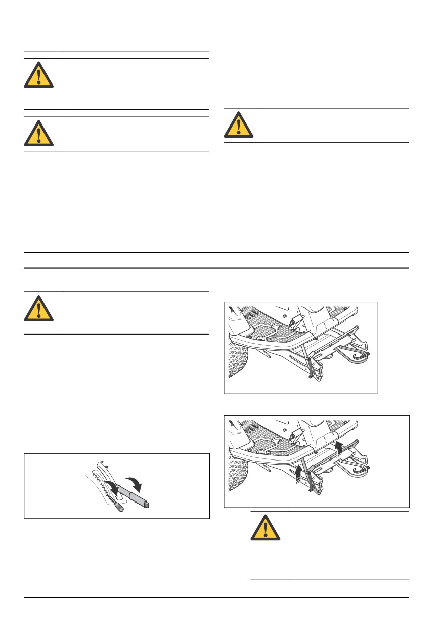
6. Push the equipment frame down. Lift the service lock
to vertical position.
2. Apply the parking brake.
3. Set the cutting height lever in the servicing position.
4. Set the lift lever for the cutting deck in the mow
position.
WARNING: The lock mechanism
can cause injury to fingers if you do
not operate it carefully. Put the
service lock in full vertical position
and hold the front edge of the
cutting deck with two hands when
you continue to the next step.
88
844 - 002 -
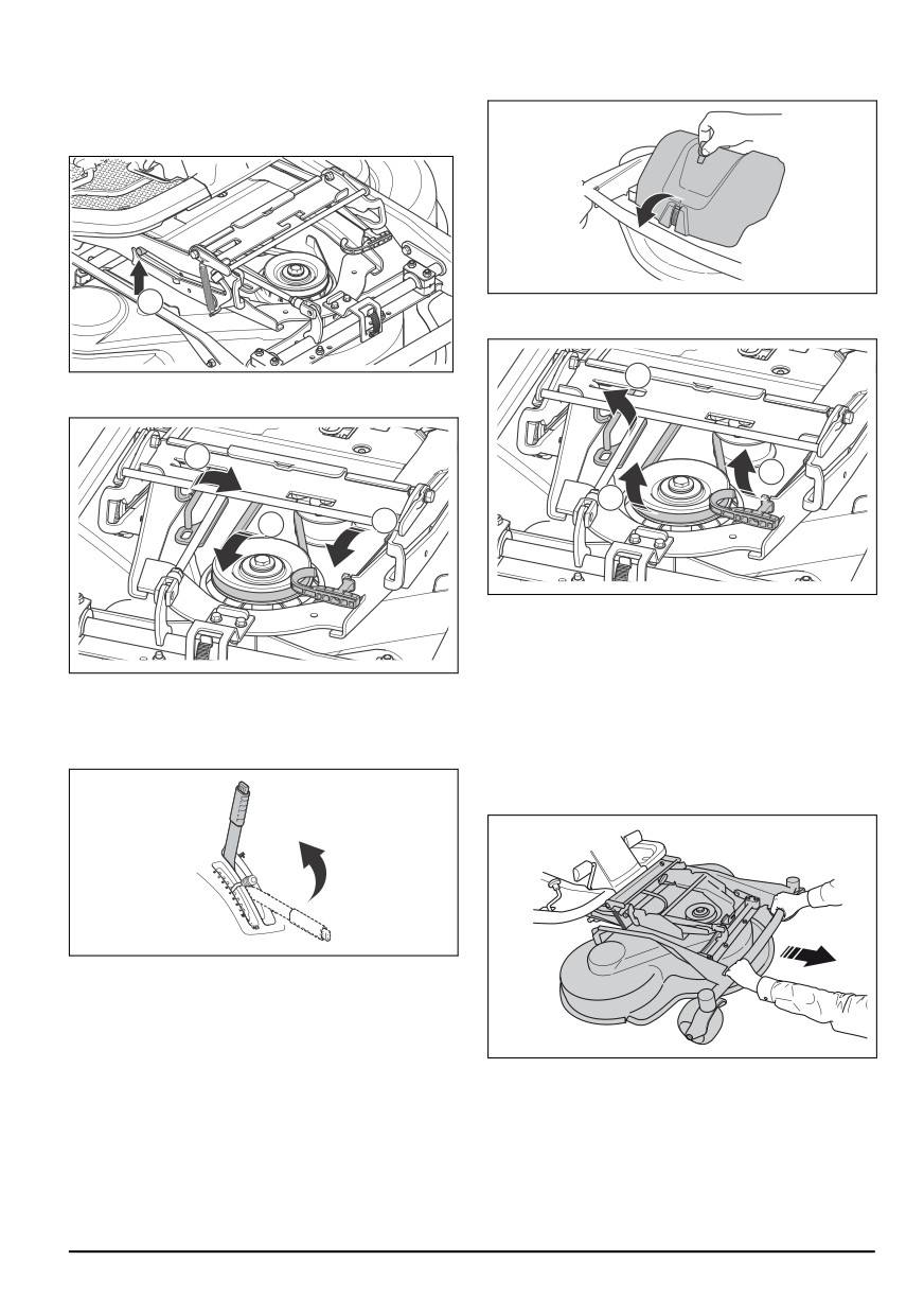
7. Lift the front edge of the cutting deck and move it
2. Release the clip on the front cover with the tool
into the equipment frame. The plugs on the cutting
attached to the ignition key, and remove the cover.
deck, one on each side, must be put in the grooves
on the equipment frame. The service lock releases
automatically.
A
3. Loosen the tension on the tension wheel for the drive
belt. (A)
C
8. Lift the cutting height stay from the stay holder and
put it in the hole for the cutting height stay (A).
A
A
B
B
C
4. Hold the spring handle with your left hand and
remove the drive belt with your right hand.
5. Pull the drive belt to the rear below the product. Do
not put it in the belt holder (B).
9. Put the drive belt around the tension wheel (B).
6. Put the spring handle in the spring holder to prevent
10. Put the spring in the spring holder (C).
that the spring falls down.
11. Set the lift lever for the cutting deck in locked
7. Lift the cutting height stay and put it in the holder for
position. The cutting deck lifts.
the cutting height stay (C).
8. Hold the front edge of the cutting deck with two
hands and pull until it stops.
12. Attach the front cover.
To remove the cutting deck
1. Do steps 1-4 in To attach the cutting deck on page
88.
844 - 002 -
89
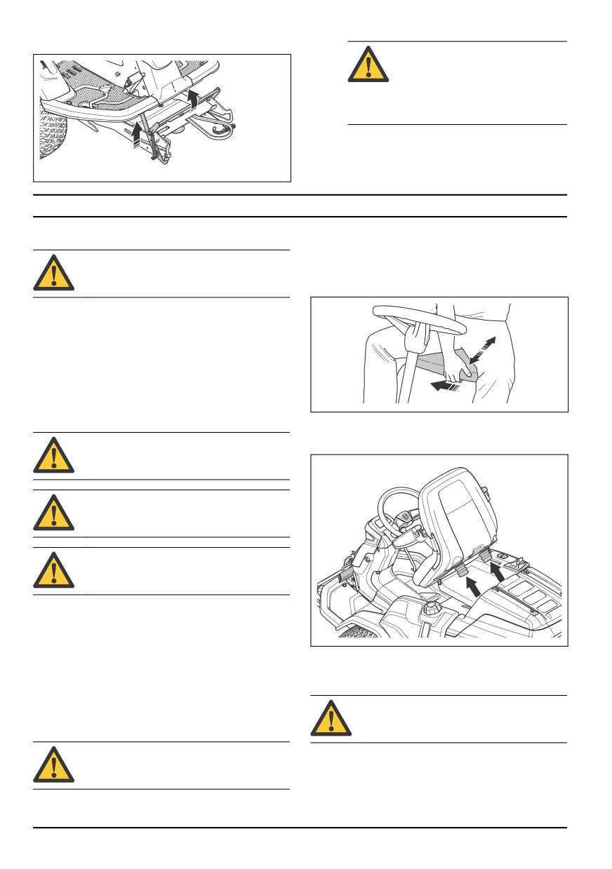
9. Lift the service lock to vertical position.
WARNING: The lock mechanism
can cause injury to fingers if you do
not operate it carefully. Hold the
front edge of the cutting deck with
two hands when you continue to the
next step.
10. Lift the front of the cutting deck until the service lock
touches the frame and pull the cutting deck out.
Operation
1. To adjust the seat forward and rearward, put your
Introduction
feet on the footrest plates.
WARNING: Before you operate the product,
2. Push the lever below the front edge of the seat, to
you must read and understand the safety
the side.
chapter.
3. Move the seat to the position that is correct for you.
To start to use Husqvarna Connect
1. Download the Husqvarna Connect app on your
mobile device.
2. Register in the Husqvarna Connect app.
3. Do the instruction steps in the Husqvarna Connect
app to connect and register the product.
To fill fuel
4. To adjust the seat springs, move the rubber stops
below the seat as given in the illustration. Put the 2
WARNING: Gasoline is very flammable. Be
stops in the front, middle or rear.
careful and refuel outdoors (see Fuel safety
on page 87).
WARNING: Do not use the fuel tank as a
support area.
CAUTION: Incorrect type of fuel can result
in engine damage.
The engine runs on gasoline with a minimum octane
rating of 91 RON (87 AKI), not mixed with oil. We
recommend biodegradable alkylate gasoline. Do not use
gasoline that contains more than 10% ethanol.
•
Do a check of the fuel level before each use and
To adjust height of the steering
refuel if necessary.
wheel
•
Do not fully fill the fuel tank. Keep a space of a
minimum 2.5 cm.
WARNING: Do not adjust the height of the
steering wheel during operation of the
To adjust the seat
product.
WARNING: Do not adjust the seat during
operation of the product.
90
844 - 002 -
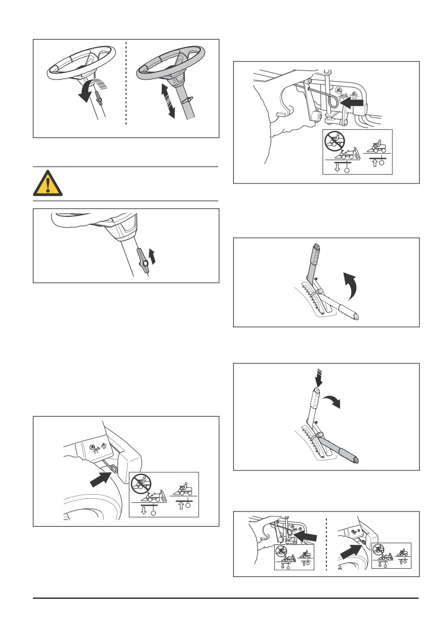
1. Turn the knob counterclockwise to loosen.
The drive system lever for the front axle for R 316TX
AWD, R 316TsX AWD is found behind the left front
wheel.
2. Adjust the height of the steering wheel.
3. Turn the knob clockwise to tighten.
CAUTION: Make sure that the long end of
the knob points up.
To lift and lower the cutting deck
To lift the cutting deck to transport position, pull the lift
lever rearward. If the engine is on, the blades stop to
rotate automatically.
To engage and disengage the drive
system
To move the product with the engine off, the drive
system must be disengaged. Pull out the drive system
To lower the cutting deck to mowing position, press the
lever fully to disengage the drive on the axle. Push the
lock button and move the lift lever forward. If the engine
drive system lever in fully to engage the drive on the
is running, the blades start to rotate automatically.
axle. Do not use middle positions.
The drive system lever for model R 316TX is found
behind the left rear wheel. Model R 316TX AWD, R
316TsX AWD has one drive system lever for the front
and one for the rear axle. The drive system lever for the
rear axle is found behind the left rear wheel.
To start the engine
1. Make sure that the drive system is engaged, see To
engage and disengage the drive system on page 91.
844 - 002 -
91
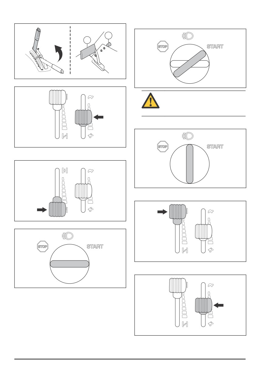
2. Lift the cutting deck and apply the parking brake.
6. When the engine starts, immediately release the
ignition key to neutral position.
2
1
3. Move the throttle control to the middle position.
CAUTION: Do not run the starter for
more than 5 seconds at a time. If the
engine does not start, wait 15 seconds
before you try again.
7. Turn the key to the lights position to make the
headlights come on.
4. If the engine is cold, move the choke control fully
rearward.
8. Push the choke control gradually forward to the end
position.
5. Turn the ignition key to the start position.
9. Let the engine run at half throttle for 3-5 minutes
before you apply heavy load.
10. Pull the throttle control rearward to full throttle
position.
92
844 - 002 -
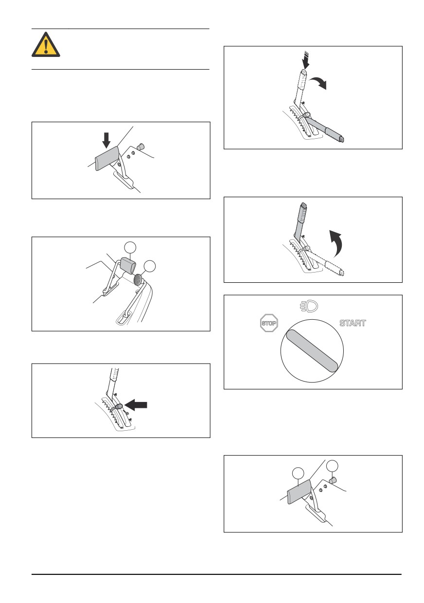
6. Press the lock button on the lift lever for the cutting
CAUTION: To engage the blades when the
deck and lower it to mow position.
engine is at full speed causes strain on the
drive belts. Do not apply full throttle until the
cutting deck is lowered to the mow position.
To operate the product
1. Start the engine.
2. Press the parking brake pedal down and then
release it to release the parking brake.
To stop the engine
1. Pull the lift lever for the cutting deck rearward to its
locked position to lift up the cutting deck. The blades
stop to rotate.
3. Carefully press down one of the speed pedals. The
speed increases the more the pedal is pressed
down. Use pedal (1) to move forward, and pedal (2)
to reverse.
1
2
2. Turn the ignition key to the STOP position.
4. Release the pedal to brake.
5. Select cutting height (1-10) with the cutting height
lever.
3. When the product stops, apply the parking brake.
To apply and release the parking
brake
1. Press the parking brake pedal down (1).
2. Press and hold the lock button (2).
2
1
3. Keep the button pressed and release the parking
brake pedal.
844 - 002 -
93
4. To release the parking brake, press the parking
•
Start with a high cutting height and decrease it
brake pedal again.
gradually.
•
Cut with blades that rotate at high speed (highest
To get a good cutting result
permitted engine speed, see Technical data on page
109). Move the product forward at low speed. If the
•
For best performance, do maintenance on the
grass is not too high and thick, you can get a good
product regularly as given in the maintenance
cutting result also at a higher speed.
schedule. Refer to Maintenance schedule on page
94.
•
Cut the grass in an irregular pattern.
•
Do not cut a wet lawn. Wet grass can give a bad
•
To get the best cutting result, cut the grass
cutting result.
frequently and use the BioClip function.
Maintenance
X = The instructions are given in this operator's manual.
Introduction
O = The instructions are not given in this operator's
WARNING: Before you do any maintenance
manual. Let an approved service agent do the
work you must read and understand the
maintenance.
safety chapter.
Note: If more than one time interval is identified in the
table, the shortest time interval is for the first
Maintenance schedule
maintenance only.
* = General maintenance done by the operator. The
instructions are not given in this operator's manual.
Maintenance
Daily maintenance
Maintenance interval
before operation
in hours
25
50
100
200
Make sure that nuts and screws are tightened
Make sure that there are no fuel or oil leaks
Clean as given in To clean the product on page 95
X
Clean the inner surface of the cutting deck, around the blades
X
Clean around the muffler
X
Make sure that the cold air intake of the engine is not blocked
X
Make sure that the safety devices are not defective
X
Examine and do a test of the brakes
X
Do a check of the engine oil level
X
Do a check of the oil level in the transmission
X
Do a check of the steering wires
X
Examine the blades in the cutting deck
X
Clean the cutting deck, below the belt covers and below the cutting
X
deck
Make sure that the tire pressure is correct
X
X
Do a check of the parking brake
X
Replace the engine oil 13
X
Replace the oil filter
X
13
Replace the engine oil first time after 8 hours of operation.
94
844 - 002 -
Maintenance
Daily maintenance
Maintenance interval
before operation
in hours
25
50
100
200
Clean the air filter
X
Replace the air filter
X
Replace the fuel filter
X
Replace the spark plug
X
Do a check of the parallelism of the cutting deck
X
X
Lubricate the belt adjuster.
X
X
Examine and adjust the steering wires
O
O
Examine the muffler and heat deflector
O
Examine the cutting deck for damages
O
Adjust the parking brake.
O
Do a check of and adjust the throttle wire
O
Clean the cooling fins on the engine and the transmission
O
Clean the engine and the transmission
O
Do a check of/adjust front and rear wheel speed, AWD models only
O
O
Do a check of the belts
O
O
Do a check of the battery
O
Do a check of the fuel hose. Replace it if necessary
O
Replace the oil in the transmission
O
O
Replace oil filter in the transmission, AWD models only
O
O
Replace the spin-on filter of the servo, AWD models only
O
O
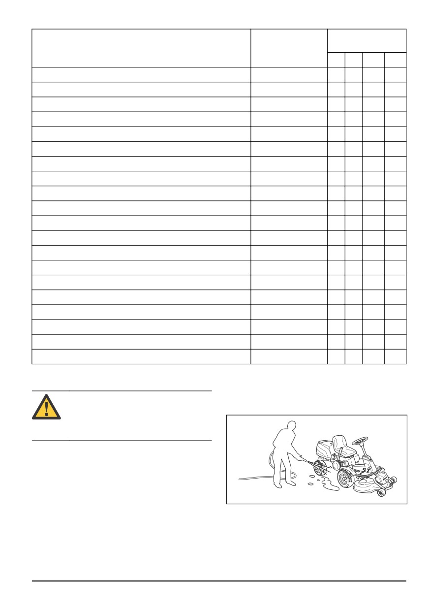
•
To clean the cutting deck, put it in the servicing
To clean the product
position and clean it with a water hose.
CAUTION: Do not use a high-pressure
•
When the product is clean, start the cutting deck for
washer or a steam cleaner. Water can go
a short period to blow off remaining water.
into bearings and electrical connections and
cause corrosion which causes damage to
the product.
Clean the product immediately after use.
•
Do not clean hot surfaces such as the engine,
muffler and exhaust system. Wait until the surfaces
are cool, then remove the grass or dirt.
•
Before you clean with water, clean with a brush.
Remove grass cuttings and dirt on and around the
transmission, the transmission air intake, and the
To clean the engine and the muffler
engine.
•
Use running water from a hose to clean the product.
Keep the engine and muffler free from grass cuttings
Do not use high pressure.
and dirt. Grass cuttings soaked in fuel or oil on the
•
Do not point the water at electrical components or
engine can increase the fire risk and the risk that the
bearings. Detergent usually increases the damage.
844 - 002 -
95
engine becomes too hot. Let the engine cool before it is
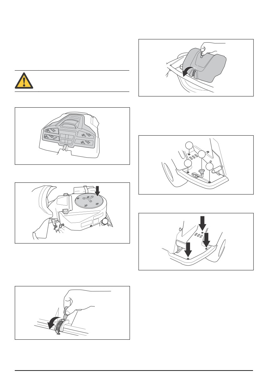
To remove the front cover
cleaned. Clean with water and a brush.
1. Release the clip on the front cover with the tool
Grass cuttings around the muffler dry quickly and are a
attached to the ignition key.
fire risk. Use a brush or remove the grass cuttings with
water when the muffler is cold.
To clean the cold air intake of the
engine
WARNING: Stop the engine. The cold air
intake rotates and can cause injury to your
fingers.
•
Make sure that the intake grille on the engine cover
2. Lift off the front cover.
is not blocked. Remove grass and dirt with a brush.
To remove the right footrest plate
1. Turn the knob on the reverse pedal (A) to remove it.
2. Remove the 3 screws (B) and remove the footrest
plate.
B
A
B
•
Open the engine cover. Make sure that the engine
B
cold air intake is not blocked. Remove grass and dirt
with a brush.
To remove the left footrest plate
•
Remove the 3 screws and remove the footrest plate.
To remove the covers
To open the engine cover
1. Fold the seat forward.
2. Release the clip on the engine cover with the tool
To examine the steering wires
attached to the ignition key.
The tension of the steering wires can decrease after a
period of time. This causes the adjustment of the
steering to change.
Examine and adjust the steering as follows:
3. Fold the engine cover rearward.
96
844 - 002 -
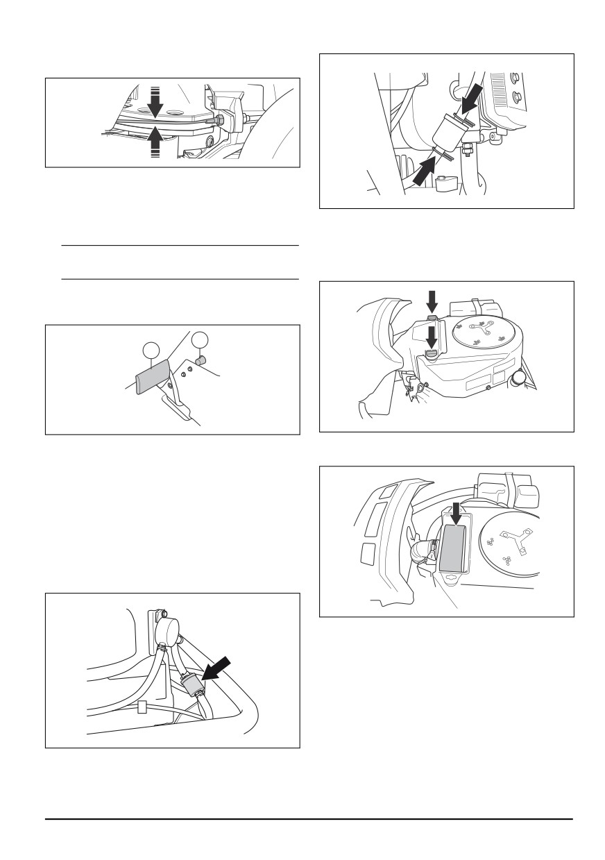
1. The steering wires are correctly tightened if you can
5. Push the hose clips against the fuel filter.
manually move them 5 mm up or down in the groove
on the steering collar.
2. If the wires are too loose, let an authorized service
agent adjust them.
To do a check of the parking brake
To clean and change the air filter
1. Park the product on a hard surface that slopes.
1. Open the engine cover.
Note: Do not park the product on a grass slope
2. Loosen the 2 knobs that hold the air filter cover and
when you do a check of the parking brake.
remove it.
2. Press the parking brake pedal down (1).
3. Press and hold the lock button (2) and release the
parking brake pedal while the button is pressed.
2
1
4. If the product starts to move, let an approved service
3. Loosen the hose clip that holds the air filter cartridge.
agent adjust the parking brake.
4. Remove the air filter cartridge from the filter housing.
5. Press the parking brake pedal again to release the
parking brake.
To replace the fuel filter
1. Open the engine cover to get access to the fuel filter.
2. Move the hose clips away from the fuel filter with a
pair of flat pliers.
3. Pull off the fuel filter from the hose ends. A small
quantity of fuel can leak.
5. Remove the foam rubber filter around the air filter
cartridge.
6. Clean the foam rubber filter with a weak detergent.
7. Let the foam rubber filter become fully dry.
8. Hit the paper filter against a hard surface to clean it.
Do not use compressed air.
9. If the paper filter does not become clean, replace it.
10. Put the foam rubber filter back around the air filter
cartridge.
4. Push the new fuel filter into the ends of the hoses.
11. Put the air filter cartridge on the air hose.
Apply liquid detergent to the ends of the fuel filter to
make the connection easier.
844 - 002 -
97
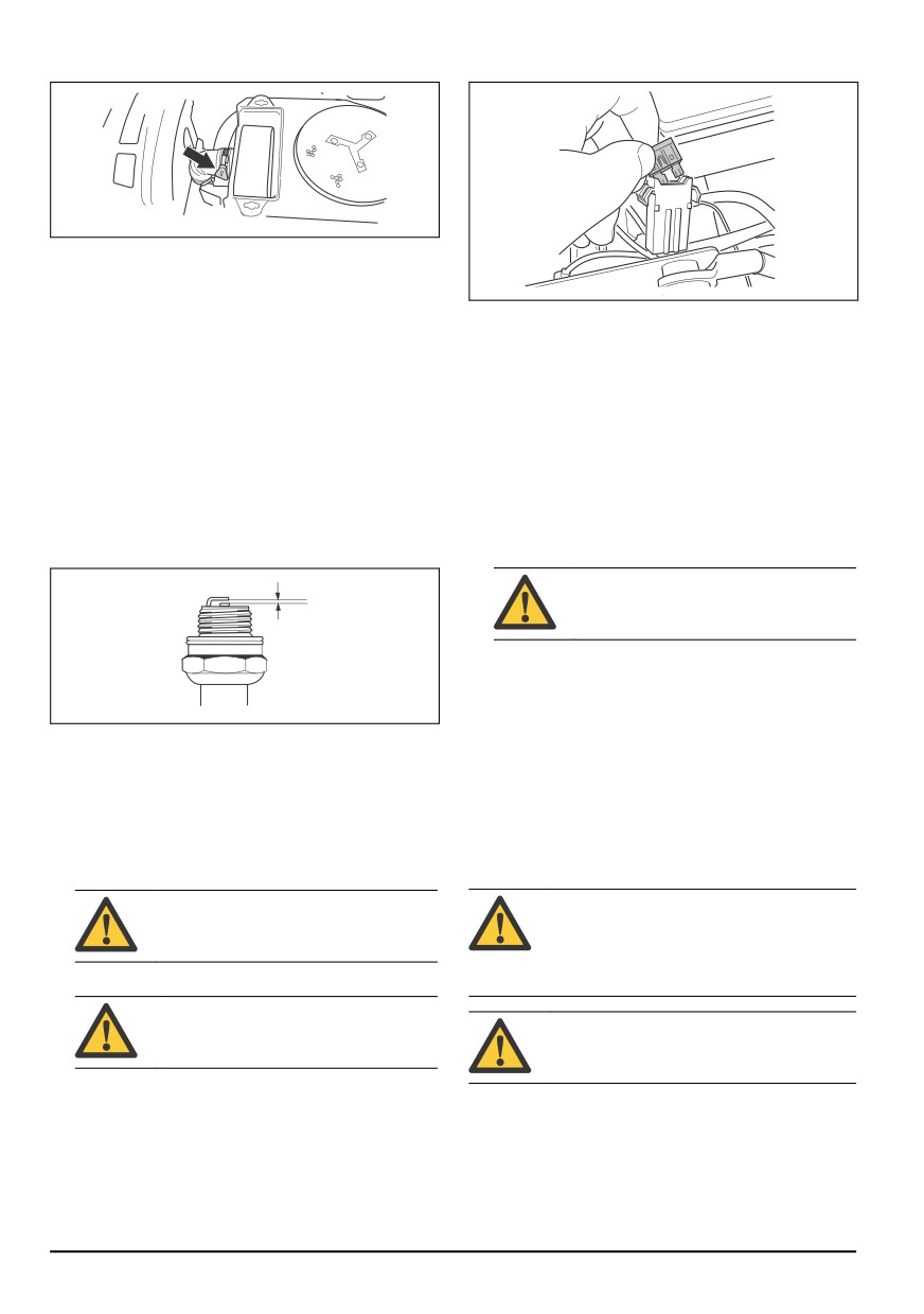
12. Attach the air filter cartridge with the hose clip.
2. Pull the fuse from the holder.
13. Attach the air filter cover and tighten the knobs.
To examine and replace the spark
plug
3. Replace the blown fuse with a new fuse of the same
type, flat pin 20 A.
1.
Open the engine cover.
4. Replace the covers.
2.
Remove the ignition cable shoe and clean around
the spark plug.
If the main fuse blows again a short period after you
replace it, there is a short circuit. Repair the short circuit
3.
Remove the spark plug with a 21 mm (0.83ʺ) spark
before you operate the product again. Let an approved
plug wrench.
service agent help you.
4.
Examine the spark plug. Replace it if the electrodes
are burned or if the insulation has cracks or
To charge the battery
damages. If the spark plug is not damaged, clean it
•
Charge the battery if it is too weak to start the
with a steel brush.
engine.
5.
Measure the electrode gap and make sure that it is
•
Use a standard battery charger.
correct. See Technical data on page 109.
CAUTION: Do not use a boost charger
or start booster. That will cause damage
to the electrical system of the product.
•
Always disconnect the charger before starting the
engine.
To do an emergency start of the
engine
6.
Bend the side electrode to adjust the electrode gap.
7.
Put the spark plug back in and turn it by hand until it
If the battery is too weak to start the engine, you can use
touches the spark plug seat.
jumper cables to do an emergency start. This product
has a 12 V system with negative ground. The product
8.
Tighten the spark plug with the spark plug wrench
that is used for the emergency start must also have a 12
until the washer is compressed.
V system with negative ground.
9.
Tighten a used spark plug ⅛ of a turn more, and a
new spark plug ¼ turn more.
To connect the jumper cables
CAUTION: Spark plugs that are not
WARNING: Risk of explosion because of
tightened correctly can cause damage to
explosive gas that comes from the battery.
the engine.
Do not connect the negative terminal of the
fully charged battery to or near the negative
10. Replace the ignition cable shoe.
terminal of the weak battery.
CAUTION: Do not try to start the engine
if the spark plug or ignition cable is
removed.
CAUTION: Do not use the battery of your
product to start other vehicles.
To replace the main fuse
1. Remove the engine cover.
A blown fuse is identified by a burned connector.
2. Remove the cover for the battery case.
1. Open the engine cover. The main fuse is in a holder
in between the battery and the engine.
98
844 - 002 -
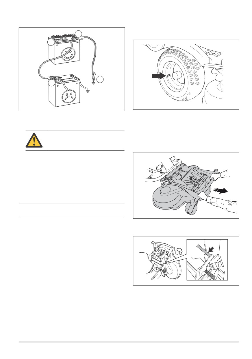
3. Connect one end of the red cable to the POSITIVE
Tire pressure
battery terminal (+) on the weak battery (A).
The correct tire pressure is 60 kPa (0.6 bar / 8.5 PSI) on
C
all 4 tires.
B
D
A
4. Connect the other end of the red cable to the
To put the cutting deck in servicing
POSITIVE battery terminal (+) on the fully charged
battery (B).
position
1. See steps 1-8 in To remove the cutting deck on
page 89.
WARNING: Do not short circuit the ends
2. Hold the front edge of the cutting deck with two
of the red cable against the chassis.
hands and pull forward until it stops.
5. Connect one end of the black cable to the
NEGATIVE battery terminal (-) on the fully charged
battery (C).
6. Connect the other end of the black cable to a
CHASSIS GROUND (D), away from the fuel tank
and the battery.
7. Replace the covers.
To remove the jumper cables
Note: Remove the jumper cables in the opposite
sequence to how you connect them.
1. Remove the BLACK cable from the chassis.
3. Lift the cutting deck to vertical position until a click
sound is heard. The cutting deck is locked
2. Remove the BLACK cable from the fully charged
automatically in the vertical position.
battery.
3. Remove the RED cable from the 2 batteries.
To put the cutting deck in mow
position
1. Hold the front edge of the cutting deck with your left
hand.
844 - 002 -
99
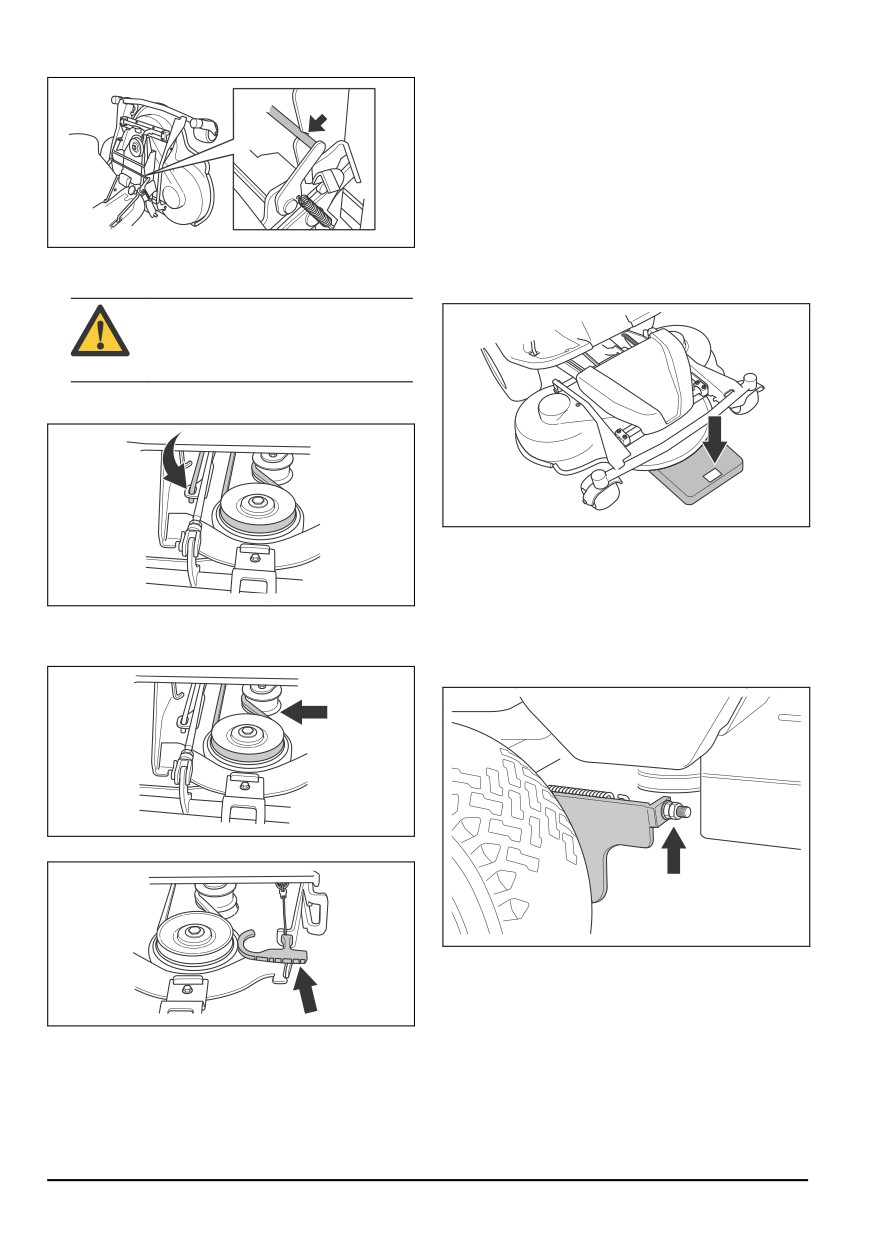
2. Loosen the lock with your right hand.
To examine and adjust the ground
pressure from the cutting deck
A correct ground pressure makes sure that the cutting
deck moves along the surface but does not press too
hard against it.
1. Make sure that the air pressure in the tires is 60 kPa
(0.6 bar / 9.0 PSI).
2. Park the product on a level surface.
3. Lower the cutting deck to mow position.
3. Fold down the cutting deck and push it in until it
stops.
4. Put a bathroom scale below the front edge of the
cutting deck.
CAUTION: The drive belt can get caught
below the cutting deck. Pull on the drive
belt loop in the belt holder before you
push the cutting deck in.
4. Lift the cutting height stay from the stay holder and
put it in the hole.
5. To make sure that no weight is applied on the
support wheels, put a wooden block between the
frame and the bathroom scale.
6. To adjust the ground pressure, turn the adjustment
5. Put the drive belt around the drive wheels. Make
screws found behind the front wheels on the right
sure that the drive belt is on the correct side of the
and left sides.
tension wheel.
7. Turn the screws right or left until the ground pressure
is between 12 and 15 kg (26.5-33 lb).
6. Put the spring in the spring holder.
To do a check of the parallelism of
the cutting deck
1. Make sure that the air pressure in the tires is 60 kPa
7. Attach the front cover.
(0.6 bar / 9.0 PSI).
8. Set the cutting height lever in one of the positions 1-
2. Park the product on a level surface.
10.
3. Lower the cutting deck to mow position.
4. Set the cutting height lever to the middle position.
100
844 - 002 -
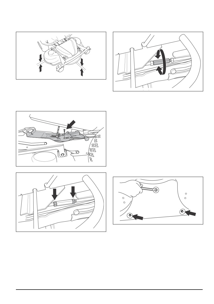
5. Measure the distance between the ground and the
4. Turn the lift strut to extend the stay or make it
front and rear edges of the cutting deck. Make sure
shorter. Extend the stay to lift the rear edge of the
that the rear edge is 4-6 mm (1/5″) higher than the
cover. Make the stay shorter to lower the rear edge
front edge.
of the cover.
To adjust the parallelism of the
cutting deck
5. Tighten the nuts on the lift strut when the adjustment
1. Remove the front cover and the right footrest plate.
is done.
2. Remove the screws that hold the belt shield and
6. Do a check of the parallelism. Refer to To do a
remove the belt shield.
check of the parallelism of the cutting deck on page
100.
7. Attach the belt shield and tighten the screws.
8. Attach the right footrest plate and the front cover.
To remove the BioClip plug
•
Remove the BioClip plug to change a Combi cutting
deck from BioClip to rear discharge of the grass.
To remove and attach the BioClip plug on
cutting deck Combi 103 and 112
1. Put the cutting deck in servicing position.
3. Loosen the nuts on the lift strut.
2. Remove the 3 screws that hold the BioClip plug and
remove the plug.
3. Attach 3 M8x15 mm screws in the screw holes for
the BioClip plug to prevent damage to the threads.
4. Put the cutting deck back in mow position.
5. Attach the BioClip plug in the opposite sequence.
To remove and attach the BioClip plug on
cutting deck Combi 94
1. Put the cutting deck in servicing position.
844 - 002 -
101
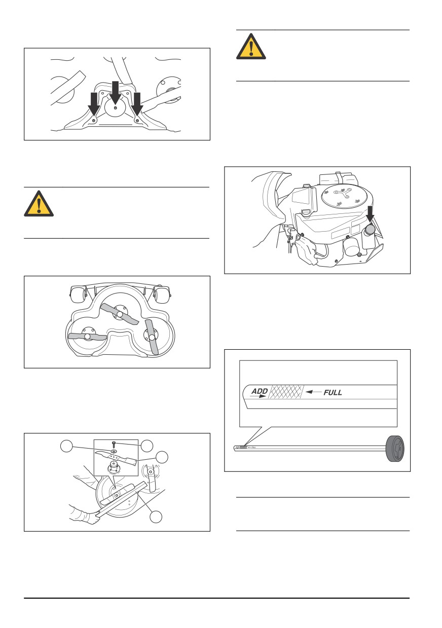
2. Remove the 3 screws that hold the BioClip plug and
WARNING: Incorrect blade type can
remove the plug.
cause objects to eject from the cutting
deck and cause serious injury. Use only
the blades given in Technical data on
page 109.
5. Attach the blade, the washer and the bolt. Tighten
the bolt with a torque of 45-50 Nm.
To do a check of the engine oil level
1. Park the product on level ground and stop the
engine.
3. Put the cutting deck back in mow position.
2. Open the engine cover.
4. Attach the BioClip plug in the opposite sequence.
3. Loosen the dipstick and pull it out.
To examine the blades
CAUTION: Damaged or incorrectly balanced
blades can cause damage to the product.
Replace damaged blades. Let an approved
service agent help you sharpen and balance
blunt blades.
1. Put the cutting deck in servicing position.
2. Look at the blades to see if they are damaged and if
it is necessary to sharpen them.
4. Clean the oil from the dipstick.
5. Put the dipstick back in. Do not tighten it.
6. Loosen and pull the dipstick out and read the oil
level.
7. The oil level must be between the marks on the
dipstick. If the level is near the ADD mark, fill oil to
the FULL mark.
3. Tighten the blade bolts with tightening torque 45-50
Nm.
To replace the blades
1. Put the cutting deck in servicing position.
2. Lock the blade with a wooden block (A).
C
B
D
8. Fill the oil through the hole that the dipstick sits in.
Fill the oil slowly.
Note: See Technical data on page 109 for the types
of engine oil that we recommend. Do not mix
A
different types of oil.
3. Loosen and remove the blade bolt (B), the washers
9. Tighten the dipstick correctly before you start the
(C) and the blade (D).
engine. Start and idle the engine for approximately
30 seconds. Stop the engine. Wait 30 seconds and
4. Assemble the new blade with the ends that have an
do a check of the oil level again.
angle in the direction of the cutting deck.
102
844 - 002 -
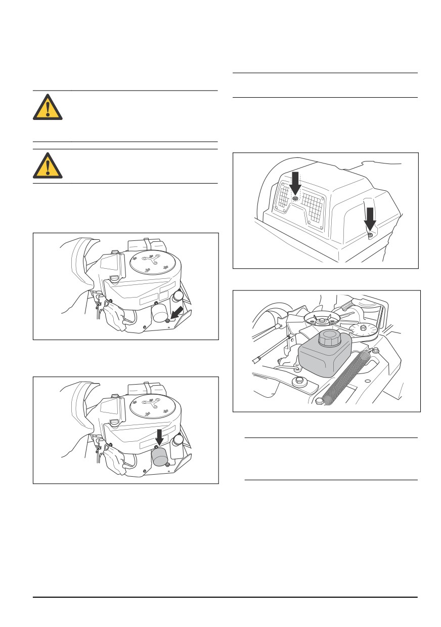
To change the engine oil and the oil
11. Stop the engine and make sure that the oil filter does
not leak.
filter
12. Fill with oil to compensate for the oil held in the new
If the engine is cold, start the engine for 1-2 minutes
oil filter.
before you drain the engine oil. This makes the engine
oil warm and easier to drain.
Note: For safe disposal of used engine oil, see Disposal
on page 108.
WARNING: Do not operate the engine for
more than 1-2 minutes before you drain the
To do a check of the transmission
engine oil. The engine oil becomes very hot
and can cause burn injuries. Let the engine
oil level
become cool before you drain the engine oil.
1. Remove the two screws, one on each side, and lift
off the transmission cover.
WARNING: If you spill engine oil on your
body, clean with soap and water.
1. Put a container below the oil drain plug on the left
side of the engine.
2. Remove the dipstick.
3. Remove the oil drain plug.
2. Make sure that the oil level in the transmission oil
tank is between the two horizontal lines on the tank.
4. Let the oil run out into the container.
5. Attach the oil drain plug and tighten it.
6. Turn the oil filter counterclockwise to remove it.
3. Fill with engine oil if the oil level is below the lower
line, but do not fill above the top line.
Note: See Technical data on page 109 for
recommended oil for R 316TX and R 316TX AWD, R
316TsX AWD. R 316TX AWD, R 316TsX AWD must
have a synthetic oil.
7. Lightly lubricate the rubber seal on the new oil filter
To lubricate the belt adjuster
with new oil.
The belt adjuster must be lubricated regularly with a
8. To attach the oil filter, turn it clockwise by hand until
good quality molybdenum disulphide grease.
the rubber seal is in position, then tighten a half turn
more.
9. Fill with new oil as given in To do a check of the
engine oil level on page 102.
10. Start the engine and let it idle for 3 minutes.
844 - 002 -
103
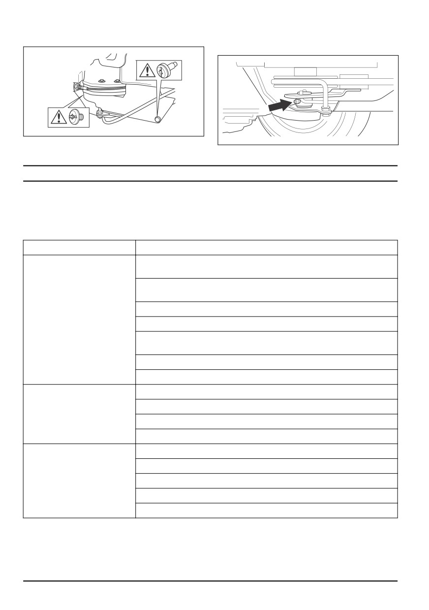
1. Remove the 2 screws that hold the belt shield and lift
2. Lubricate with a grease gun through the nipple at the
it off.
right side, below the lower belt pulley. Lubricate until
grease is pushed out of the rear side of the nipple.
3. Attach the belt shield and tighten the 2 screws.
Troubleshooting
Troubleshooting schedule
If you cannot find a solution to your problems in this
owner's manual, speak to your Husqvarna service
agent.
Problem
Cause
The starter motor does not turn
The parking brake is not applied. See To apply and release the parking brake on
the engine over
page 93.
The lift lever for the cutting deck is in mow position. See To lift and lower the cut-
ting deck on page 91.
The main fuse is blown. See To replace the main fuse on page 98.
The ignition lock is defective.
The connection between the cable and the battery is bad. See Battery safety on
page 87.
The battery is too weak. See To charge the battery on page 98.
The starter motor is defective.
The engine does not start when
There is no fuel in the fuel tank. See To fill fuel on page 90.
the start motor turns the engine
over
The spark plug is defective.
The ignition cable is defective.
There is dirt in the carburettor or fuel line.
The engine does not run
The spark plug is defective.
smoothly
The carburettor is incorrectly set.
The air filter is clogged. See To clean and change the air filter on page 97.
The fuel tank vent is blocked.
There is dirt in the carburetor or fuel line.
104
844 - 002 -
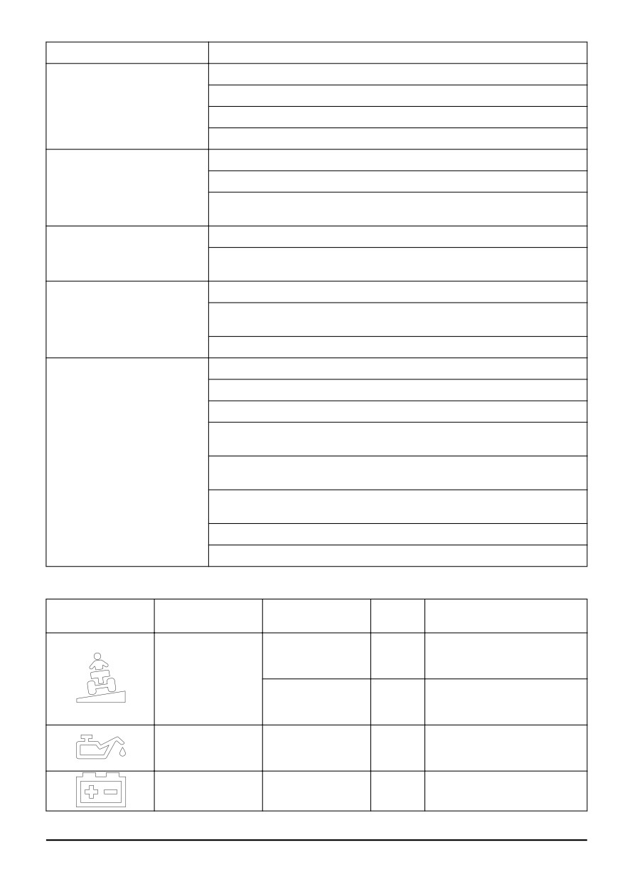
Problem
Cause
The engine apparently has no
The air filter is clogged. See To clean and change the air filter on page 97.
power
The spark plug is defective.
There is dirt in the carburetor or fuel line.
The throttle cable is incorrectly adjusted.
The transmission does not have
The transmission cold air intake or the cooling fins are blocked.
sufficient power
The fan on the transmission is damaged.
There is no oil in the transmission or the oil level is too low. See To do a check
of the transmission oil level on page 103.
The battery does not charge
The battery is defective. See Battery safety on page 87.
The connection at the cable connectors on the battery terminals is bad. See Bat-
tery safety on page 87.
There is vibration in the product
The blades are loose. See To examine the blades on page 102.
One or more of the blades are unbalanced. See To examine the blades on page
102.
The engine is loose.
The cutting result is unsatisfac-
The blades are blunt. See To examine the blades on page 102.
tory
The grass is long or wet. See To get a good cutting result on page 94.
The cutting deck is skew.
There is grass blockage in the cutting deck. See To clean the product on page
95.
The tire pressure is different on the right and left sides. See Tire pressure on pa-
ge 99.
The product is operated at a too high speed. See To get a good cutting result on
page 94.
The engine speed is too low. See To get a good cutting result on page 94.
The drive belt slips.
Display - Troubleshooting
Indication on the
Symbol
Name
Sound
Cause
display
You operate the product in a slo-
The symbol shows.
-
pe >10°. Refer to Safety instruc-
tions for operation on page 85.
Slope indicator
You operate the product in a slo-
The symbol flashes.
-
pe >15°. Refer to Safety instruc-
tions for operation on page 85.
Low oil pressure. Refer to To do
1 long
Oil pressure sensor
The symbol shows.
a check of the engine oil level on
sound.
page 102.
1 long
Low voltage. Refer to To charge
Battery level indicator
The symbol shows.
sound.
the battery on page 98.
844 - 002 -
105
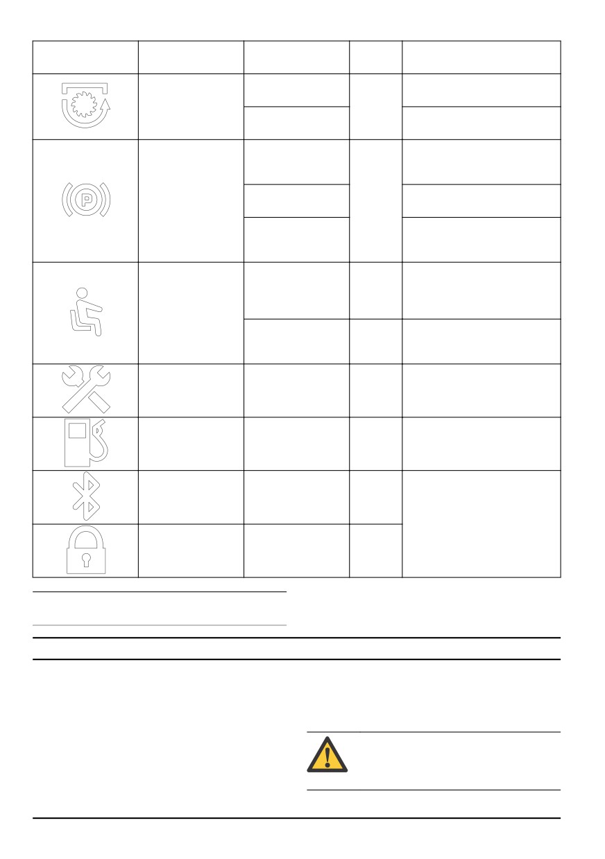
Indication on the
Symbol
Name
Sound
Cause
display
The symbol shows.
The drive of the blades is enga-
ged.
Rotating blades indi-
-
cator
The symbol flashes.
Incorrect start procedure. Refer
to Start conditions on page 86.
The parking brake engaged. Re-
The symbol shows.
fer to To apply and release the
parking brake on page 93.
Parking brake indica-
Incorrect start procedure. Refer
The symbol flashes.
-
tor
to Start conditions on page 86.
Defective parking brake. Speak
The symbol flashes
to your Husqvarna servicing dea-
quickly.
ler.
The operator presence control is
5 short
disengaged when you try to start
The symbol flashes.
sounds.
the engine. Refer to To start the
Operator presence
engine on page 91.
control (OPC) indica-
tor
Defective operator presence con-
The symbol flashes
-
trol. Speak to your Husqvarna
quickly.
servicing dealer.
5 short
Servicing is necessary. Speak to
Servicing indicator
The symbol shows.
sounds.
your Husqvarna servicing dealer.
Low fuel level indica-
1 short
Low fuel. Refer to To fill fuel on
The symbol shows.
tor
sound.
page 90.
The symbol flashes.
Bluetooth® indicator
-
The product is locked. Unlock
your product with Husqvarna
Connect.
Digital lock
The symbol shows.
-
Note: The look of the display can be different between
different models.
Transportation, storage and disposal
Transportation
To safely attach the product for transport
•
The product is heavy and can cause crush injuries.
Before you attach the product, you must read and
Be careful when you load it onto or off a vehicle or
understand the safety chapter. Refer to Transport safety
trailer.
on page 87.
•
Use an approved trailer for transportation of the
WARNING: The parking brake is not
product.
sufficient to lock the product during
•
Make sure that you have knowledge of local road
transport. Attach the product tightly to the
traffic regulations before transportation of the
load area.
product in a trailer or on roads.
106
844 - 002 -
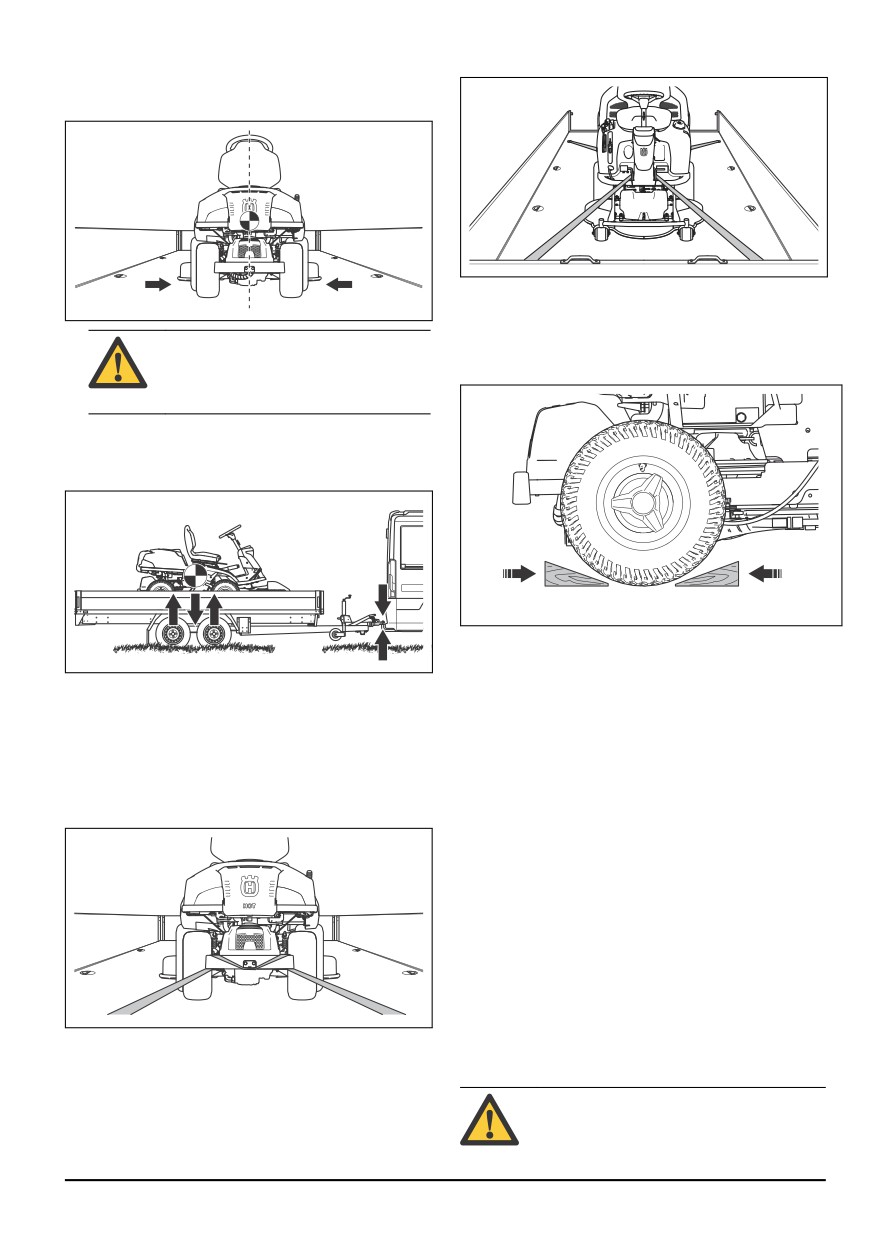
Equipment: 2 approved straps and 4 wedge shaped
9. Put the second strap around the frame tunnel.
wheel blocks.
1. Park the product in the center of the load area.
10. Attach the strap to the load area.
11. Tighten the strap in the direction of the front of the
load area to attach the product to the load area.
CAUTION: For transport in transport
vehicles with a cover. Make sure to let
12. Put the wheel blocks in front of and behind the rear
wheels.
the product become cool before you put
the product under the cover.
2. Make sure that the center of gravity of the product is
above the wheel axle of the transport vehicle. If a
trailer is used for transport, make sure that the down
force on your tow bar is correct.
To tow the product
The product has a hydrostatic transmission. To prevent
3.
Apply the parking brake.
damage to the transmission, tow the product short
4.
If the product has Bluetooth®, lock the product with
distances only and at low speed.
Husqvarna Connect.
Disengage the transmission before you tow the product.
5.
Lower the cutting deck to the mow position.
Refer to To engage and disengage the drive system on
6.
Remove all loose objects.
page 91.
7.
Assemble the first strap through the rear
Storage
transmission frame. Refer to the illustration.
Prepare the product for storage at the end of the
season, and before more than 30 days of storage. If you
keep fuel in the fuel tank for 30 days or more, tacky
particles can cause blockage in the carburetor. This has
a negative effect on the engine function.
To prevent tacky particles during storage, add a
stabilizer. If alkylate gasoline is used, stabilizer is not
necessary. If you use standard gasoline, do not change
to alkylate gasoline. This can cause sensitive rubber
parts to become hard. Add stabilizer to the fuel in the
tank or in the container used for storage. Always use the
mixing ratios given by the manufacturer. Run the engine
8.
Tighten the strap rearward to attach the product to
for a minimum of 10 minutes after you add the stabilizer
the load area.
until it flows into the carburetor.
WARNING: Do not keep the product with
fuel in the tank in an indoor location or in
locations with bad airflow. Risk of fire if fuel
844 - 002 -
107

fumes come near open flames, sparks, or
pilot lights in for example boilers, hot water
tanks and clothes dryers.
WARNING: Remove grass, leaves and
other flammable materials from the product
to decrease the risk of fire. Let the product
become cool before you put it in storage.
•
Clean the product, see To clean the product on page
95. Repair paint damages to prevent corrosion.
•
Examine the product for worn or damaged parts and
tighten loose screws and nuts.
•
Remove the battery. Clean it, charge it, and keep it
cool during storage.
•
Change the engine oil, and discard the waste oil.
•
Empty the fuel tank. Start the engine and run it until
there is no remaining fuel in the carburetor.
Note: Do not empty the fuel tank and carburetor if a
stabilizer has been added.
•
Remove the plugs and put about a tablespoon of
engine oil into each cylinder. Manually turn the
engine shaft to apply the oil and put the plugs back
on.
•
Lubricate all grease nipples, joints and axles.
•
Keep the product in a clean and dry area and cover
it for more protection.
•
A cover for protection of your product during storage
or transport is available at your dealer.
Disposal
•
Chemicals can be dangerous and must not be
discarded on the ground. Always discard used
chemicals at a service center or an applicable
disposal location.
•
When the product is worn out, send it to the dealer
or to an applicable recycling location.
•
Oil, oil filters, fuel and the battery can have negative
effects on the environment. Obey the local recycling
requirements and applicable regulations.
•
Do not discard the battery as domestic waste.
•
Send the battery to a Husqvarna service agent or
discard it at a disposal location for used batteries.
108
844 - 002 -

Technical data
Technical data
R 316TX
R 316TX AWD
R 316TsX AWD
Dimensions
Length without cutting deck, mm
2028
2013
2013
Width without cutting deck, mm
883
883
883
Height, mm
1165
1165
1165
Weight without cutting deck, with empty
238
236
248
tanks, kg
Wheel base, mm
887
887
887
Track width, front, mm
712
712
712
Track width, rear, mm
627
627
627
Tire dimensions
16×6.50×8
16×6.50×8
16×6.50×8
Tire pressure, rear - front, kPa / bar / PSI
60 / 0.6 / 8.5
60 / 0.6 / 8.5
60 / 0.6 / 8.5
Max. gradient, degrees °
10
10
10
Engine
Brand / Model
Kawasaki / FS481V
Kawasaki / FS481V
Kawasaki / FS481V
Nominal engine output, kW 14
10.6
10.6
10.6
Displacement, cm3
603
603
603
Max. engine speed, rpm
2900 ± 100
2900 ± 100
3100 ± 100
Fuel, min. octane grade lead-free
91
91
91
Tank volume, litres
12
12
12
Oil
Class SF, SG, SH or
Class SF, SG, SH or
Class SF, SG, SH or
SJ SAE40, SAE30,
SJ SAE40, SAE30,
SJ SAE40, SAE30,
SAE10W-30,
SAE10W-30,
SAE10W-30,
SAE10W-40 or
SAE10W-40 or
SAE10W-40 or
SAE5W-20
SAE5W-20
SAE5W-20
Oil volume incl. filter, litres
1.7
1.7
1.7
Oil volume excl. filter, litres
1.5
1.5
1.5
Start motor
Electric start 12V
Electric start 12V
Electric start 12V
Transmission
Brand
Tuff Torq
Tuff Torq
Tuff Torq
14
The power rating of the engine indicated is the average net output (at specified rpm) of a typical production
engine for the engine model measured to SAE standard J1349/ISO1585. Mass production engines may differ
from this value. Actual power output for the engine installed on the final product will depend on the operating
speed, environmental conditions and other values.
844 - 002 -
109
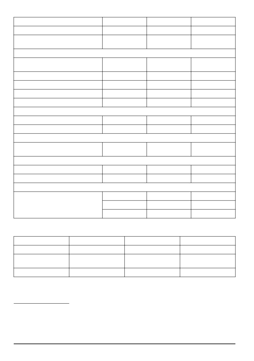
R 316TX
R 316TX AWD
R 316TsX AWD
Model
K46H
K574A
K574RA
Oil, class SF-CC
SAE 10W/40
SAE 10W/50 Synthe-
SAE 10W/50 Synthe-
tic
tic
Electrical system
Type
12V, negative eart-
12V, negative eart-
12V, negative eart-
hed
hed
hed
Battery
12V, 24Ah
12V, 24Ah
12V, 24Ah
Spark plug
NGK BPR4ES
NGK BPR4ES
NGK BPR4ES
Electrode gap, mm/inch
0.75/0.030
0.75/0.030
0.75/0.030
Lamps
Dual LED lights
Dual LED lights
Dual LED lights
Noise emissions15
Sound power level, measured dB(A)
97
97
98
Sound power level, guaranteed dB(A)
98
98
99
Sound levels16
Sound pressure level at the operators ear,
86
86
87
dB(A)
Vibration levels17
Vibration level on the steering wheel, m/s2
2.5
2.5
2.5
Vibration level in the seat, m/s2
0.7
0.7
0.7
Cutting deck
Type
Combi 94
Combi 94
Combi 94
Combi 103
Combi 103
Combi 103
Combi 112
Combi 112
Combi 112
Cutting deck
Combi 94
Combi 103
Combi 112
Cutting width, mm
940
1030
1120
Cutting height, 10 posi-
25-75
25-75
25-75
tions, mm
Weight, kg
44
49
52
15
Noise emissions in the environment measured as sound power (LWA) in conformity with EC directive
2006/14/EC.
16
Noise pressure level according to EN ISO 5395. Reported data for noise pressure level has a typical statistical
dispersion (standard deviation) of 1.2 dB(A).
17
Vibration level according to EN ISO 5395. Reported data for vibration level has a typical statistical dispersion
(standard deviation) of 0.2 m/s2 (steering wheel) and 0.8 m/s2 (seat).
110
844 - 002 -
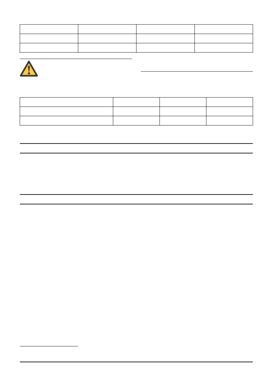
Blade
Combi 94
Combi 103
Combi 112
Blade length, mm
358
388
420
Article number
579 65 25-10
504 18 82-10
544 10 28-10
injury. Do not use other cutting deck types
WARNING: To use a cutting deck that is not
than specified in this manual.
approved for the product can cause objects
to eject at high speed and cause serious
Radio frequency data
R 316TX
R 316TX AWD
R 316TsX AWD
Frequency range, MHz
2402-2480
2402-2480
2402-2480
Output power18, dBm
-5.2
-5.2
-5.2
Service
When you send an order for the spare parts, give
Service
information about the purchase year, model, type, and
Do a yearly check at an authorized service center to
serial number.
make sure that the product functions safely and at its
Always use original spare parts.
best during high season. The best time to do a servicing
or overhaul of the product is low season.
Warranty
Transmission warranty
Applies to R 316TX AWD, R 316TsX AWD only.
The transmission warranty is only applicable if checks
are done of the front and rear wheel rotation speed as
given in the maintenance schedule. To prevent damage
to the transmission system, let an authorized service
agent adjust it. Refer to the table values specified in the
workshop manual.
18
Measured at 2440 MHz.
844 - 002 -
111
EC Declaration of Conformity
EC Declaration of Conformity
has issued reports regarding the assessment of
conformity according to annex VI of the COUNCIL’S
Husqvarna AB, SE-561 82 Huskvarna, Sweden, tel:
DIRECTIVE of May 8, 2000 ”relating to the noise
+46-36-146500, declares that the ride-on lawn mower
emissions in the environment” 2006/14/EC.
Husqvarna R 316TX and R 316TX AWD, R 316TsX
The certificates have the numbers: 01/901/306,
AWD from 2014's serial numbers and onwards (the year
01/901/307
is clearly stated in plain text on the rating plate with
subsequent serial number), comply with the
Huskvarna, 2018-09-30
requirements of the COUNCIL’S DIRECTIVE:
•
of May 17, 2006 ”relating to machinery” 2006/42/EC.
•
of May 8, 2000 ”relating to the noise emissions in the
environment” 2006/14/EC.
•
of June 8, 2011 "restriction of use of certain
hazardous substances" 2011/65/EU.
Claes Losdal, Development Manager/Garden Products
•
of 16 April, 2014 "relating to radio equipment"
(Authorized representative for Husqvarna AB and
2014/53/EU.
responsible for technical documentation) Operator
Information regarding noise emissions and the mowing
presence control
width, see Technical data.
The product complies with applicable parts of the
harmonised standard:
EN ISO 12100-2, EN ISO 5395-1, EN ISO 5395-3, EN
ISO 14982, EN 300 328, EN 50581
If not otherwise stated, the above listed standards are
the latest published versions.
Notified body: 0404, RISE SMP Svensk
Maskinprovning AB, Box 7035, SE-750 07 Uppsala
Registered trademarks
The Bluetooth® word mark and logos are registered
trademarks owned by Bluetooth SIG, inc. and any use of
such marks by Husqvarna is under license.
112
844 - 002 -