Ridgid FULL ROUND HEAD FRAMING NAILER R350RHA. OPERATOR’S MANUAL


  Index      Manuals 


Search            copyright infringement  


Ridgid FULL ROUND HEAD FRAMING NAILER R350RHA. OPERATOR’S MANUAL


-------------------------------------------------------------------------------------------------------------------------------------------------------------
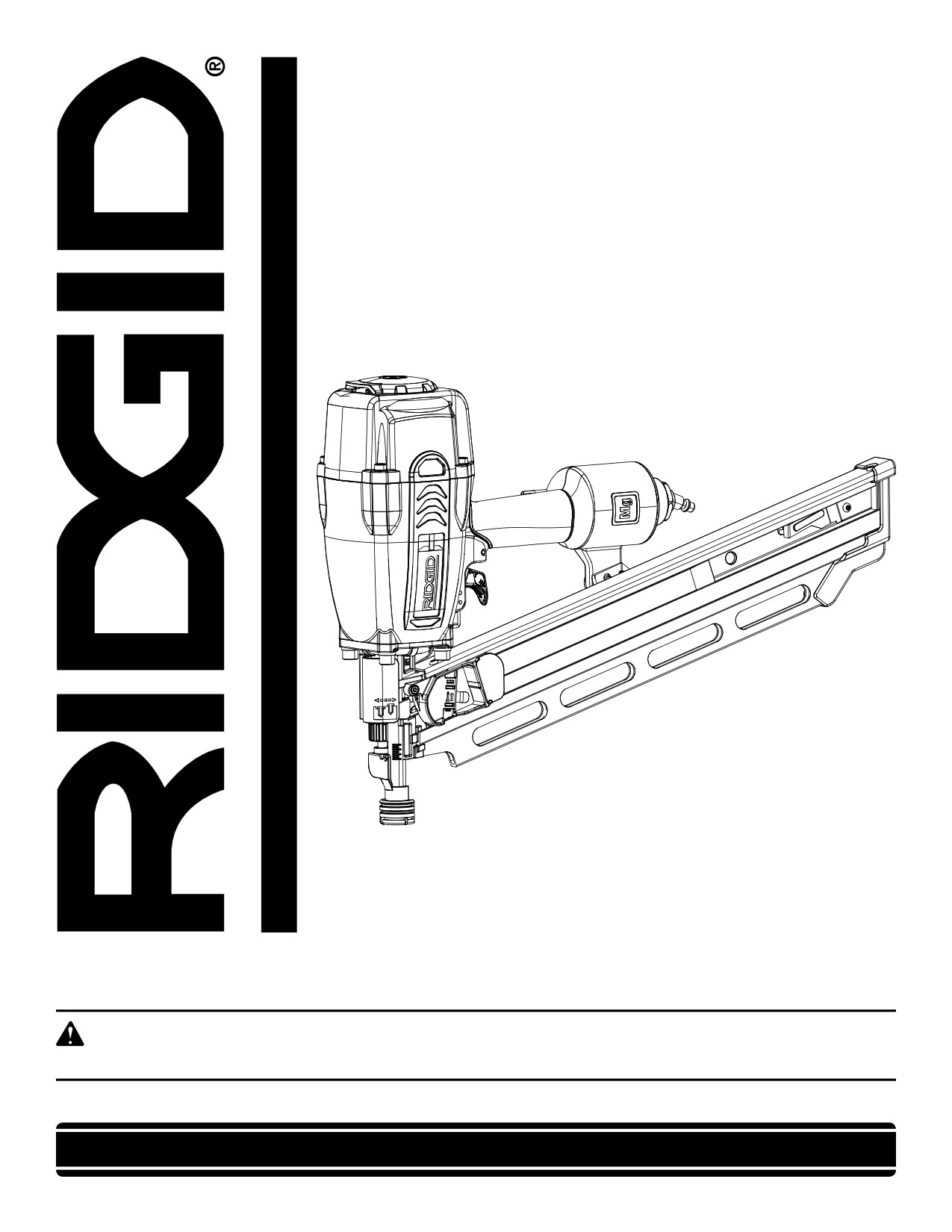
OPERATOR’S MANUAL
FULL ROUND HEAD
FRAMING NAILER
R350RHA
Your framing nailer has been engineered and manufactured to our high standards for dependability, ease of operation, and
operator safety. When properly cared for, it will give you years of rugged, trouble-free performance.
WARNING:
To reduce the risk of injury, the user must read and understand the operator’s manual before using this product.
Thank you for buying a RIDGID product.
SAVE THIS MANUAL FOR FUTURE REFERENCE

-------------------------------------------------------------------------------------------------------------------------------------------------------------

TABLE OF CONTENTS
„ Introduction
2
„ General Safety Rules
3
„ Specific Safety Rules
4-5
„ Symbols
6-7
„ Glossary of Terms
7
„ Features
8-9
„ Assembly
10
„ Operation
10-16
„ Maintenance
17
„ Accessories
18
„ Troubleshooting
18
„ Warranty
19
„ Customer Service Information
20
INTRODUCTION
This tool has many features for making its use more pleasant and enjoyable. Safety, performance, and dependability have
been given top priority in the design of this product making it easy to maintain and operate.
2

-------------------------------------------------------------------------------------------------------------------------------------------------------------

GENERAL SAFETY RULES
„ Keep fingers away from trigger when not driving fasten-
DANGER
ers to avoid accidental firing.
READ AND UNDERSTAND TOOL LABELS AND
„ Do not overreach. Keep proper footing and balance
MANUAL. Failure to follow warnings could result
at all times. Proper footing and balance enables better
in DEATH or SERIOUS INJURY.
control of the tool in unexpected situations.
„ Use safety equipment. Always wear eye protection.
SAVE THESE INSTRUCTIONS
Dust mask, nonskid safety shoes, hard hat, or hearing
protection must be used for appropriate conditions.
WORK AREA
„ Do not use on a ladder or unstable support. Stable
„ Keep your work area clean and well lit. Cluttered
footing on a solid surface enables better control of the
benches and dark areas invite accidents.
tool in unexpected situations.
„ Do not operate power tools in explosive atmospheres,
such as in the presence of flammable liquids, gases,
TOOL USE AND CARE
or dust. Power tools create sparks which may ignite the
„ Do not force tool. Use the correct tool for your
dust or fumes.
application. The correct tool will do the job better and
safer at the rate for which it is designed.
„ Keep bystanders, children, and visitors away while
operating a power tool. Distractions can cause you to
„ Do not use tool if trigger does not actuate properly.
lose control.
Any tool that cannot be controlled with the trigger is
dangerous and must be repaired.
PERSONAL SAFETY
„ Check operation of the workpiece contact mechanism
„ Eye protection which conforms to ANSI specifications
frequently. Do not use the tool if the workpiece contact
and provides protection against flying particles both
mechanism is not working correctly as accidental driving
from the FRONT and SIDE should ALWAYS be worn
of a fastener may result. Do not interfere with the proper
by the operator and others in the work area when
operation of the workpiece contact mechanism.
loading, operating or servicing this tool. Eye protection
„ Store idle tools out of the reach of children and other
is required to guard against flying fasteners and debris,
untrained persons. Tools are dangerous in the hands of
which could cause severe eye injury.
untrained users.
„ The employer and/or user must ensure that proper
„ Maintain tools with care. Follow maintenance instruc-
eye protection is worn. We recommend Wide Vision
tions. Properly maintained tools are easier to control.
Safety Mask for use over eyeglasses or standard safety
„ Check for misalignment or binding of moving parts,
glasses that provide protection against flying particles
breakage of parts, and any other condition that may
both from the front and side. Always use eye protection
affect the tool’s operation. If damaged, have the tool
which is marked to comply with ANSI Z87.1.
serviced before using. Many accidents are caused by
„ Additional safety protection will be required in some
poorly maintained tools.
environments. For example, the working area may in-
„ Use only fasteners that are recommended for your
clude exposure to noise level which can lead to hearing
model.
damage. The employer and user must ensure that any
„ Keep the tool and its handle dry, clean and free from
necessary hearing protection is provided and used by the
oil and grease. Always use a clean cloth when clean-
operator and others in the work area. Some environments
ing. Never use brake fluids, gasoline, petroleum-based
will require the use of head protection equipment. When
products, or any strong solvents to clean your tool. Fol-
required, the employer and user must ensure that head
lowing this rule will reduce the risk of loss of control and
protection conforming to ANSI Z89.1-1997 is used.
deterioration of the enclosure plastic.
„ Stay alert, watch what you are doing and use common
sense when operating a power tool. Do not use tool
SERVICE
while tired or under the influence of drugs, alcohol,
„ Tool service must be performed only by qualified re-
or medication. A moment of inattention while operating
pair personnel. Service or maintenance performed by
power tools may result in serious personal injury.
unqualified personnel may result in a risk of injury.
„ Dress properly. Do not wear loose clothing or jewelry.
„ When servicing a tool, use only identical replacement
Contain long hair. Keep your hair, clothing, and gloves
parts. Follow instructions in the Maintenance sec-
away from moving parts. Loose clothes, jewelry, or long
tion of this manual. Use of unauthorized parts or failure
hair can be caught in moving parts.
to follow Maintenance instructions may create a risk of
injury.
3

-------------------------------------------------------------------------------------------------------------------------------------------------------------

SPECIFIC SAFETY RULES
„ Know your power tool. Read operator’s manual care-
„ Always be aware that misuse and improper handling
fully. Learn its applications and limitations, as well as the
of this tool can cause injury to yourself and others.
specific potential hazards related to this tool. Following
„ Never clamp or tape the trigger or workpiece contact
this rule will reduce the risk of electric shock, fire, or seri-
in an actuated position.
ous injury.
„ Never leave a tool unattended with the air hose at-
„ Always wear safety glasses with side shields.
tached.
Everyday glasses have only impact resistant lenses. They
„ Do not operate this tool if it does not contain a legible
are NOT safety glasses. Following this rule will reduce
warning label.
the risk of eye injury.
„ Do not continue to use a tool that leaks air or does
„ Protect your lungs. Wear a face or dust mask if the op-
not function properly.
eration is dusty. Following this rule will reduce the risk of
OPERATION
serious personal injury.
„ Always assume that the tool contains fasteners.
„ Protect your hearing. Wear hearing protection during
„ Do not carry the tool from place to place holding the
extended periods of operation. Following this rule will
trigger. Accidental discharge could result.
reduce the risk of serious personal injury.
„ Always handle the tool with care:
„ Make sure the hose is free of obstructions or snags.
Entangled or snarled hoses can cause loss of balance or
• Respect the tool as a working implement.
footing and may become damaged.
• Never engage in horseplay.
„ Use the tool only for its intended use. Do not discharge
• Never pull the trigger unless nose is directed toward
fasteners into open air.
the work.
„ Do not drive fasteners near edge of material. The
• Keep others a safe distance from the tool while tool is in
workpiece may split causing the fastener to ricochet,
operation as accidental actuation may occur, possibly
injuring you or a co-worker. Be aware that the nail may
causing injury.
follow the grain of the wood, causing it to protrude un-
„ Choice of triggering method is important. Check
expectedly from the side of the work material.
manual for triggering options.
„ Keep hands and body parts clear of immediate work
„ Do not point the tool toward yourself or anyone
area. Hold workpiece with clamps when necessary to
whether it contains fasteners or not.
keep hands and body out of potential harm. Be sure the
„ Do not actuate the tool unless you intend to drive a
workpiece is properly secured before pressing the nailer
fastener into the workpiece.
against the material. The workpiece contact may cause
the work material to shift unexpectedly.
„ During normal use the tool will recoil immediately
after driving a fastener. This is a normal function of
„ Keep face and body parts away from back of the tool
the tool. Do not attempt to prevent the recoil by holding
cap when working in restricted areas. Sudden recoil
the nailer against the work. Restriction to the recoil can
can result in impact to the body, especially when nailing
result in a second fastener being driven from the nailer.
into hard or dense material.
Grip the handle firmly, let the tool do the work and do not
„ Use the pneumatic tool only for the purpose for which
place second hand on top of tool or near exhaust at any
it was designed.
time. Failure to heed this warning can result in serious
„ Never use this tool in a manner that could cause a
personal injury.
fastener to be directed toward anything other than
„ Do not drive fasteners on top of other fasteners or with
the workpiece.
the tool at an overly steep angle as this may cause
„ Do not use the tool as a hammer.
deflection of fasteners which could cause injury.
„ Always carry the tool by the handle. Never carry the
„ Do not drive fasteners close to the edge of the
tool by the air hose.
workpiece as the wood may split, allowing the fas-
„ Do not alter or modify this tool from the original design
tener to be deflected possibly causing injury.
or function without approval from the manufacturer.
4

-------------------------------------------------------------------------------------------------------------------------------------------------------------

SPECIFIC SAFETY RULES
AIR SUPPLY AND CONNECTIONS
LOADING TOOL
„ Do not use oxygen, combustible gases or bottled
„ Do not load the tool with fasteners when any one of
gases as a power source for this tool as tool will
the operating controls is activated.
explode, possibly causing injury or death.
When loading tool:
„ Do not use with an air compressor which can poten-
„ Never place a hand or any part of body in fastener
tially exceed 200 P.S.I. as tool may burst, possibly
discharge area of tool.
causing injury.
„ Never point tool at anyone.
„ The connector on the tool must not hold pressure
„ Do not pull the trigger or depress the workpiece
when air supply is disconnected. If an incorrect fitting
contact as accidental actuation may occur, possibly
is used, the tool can remain charged with air after discon-
causing injury.
necting and thus will be able to drive a fastener even after
the air line is disconnected, possibly causing injury.
SAVE THESE INSTRUCTIONS
„ Always disconnect air supply:
„ Refer to them frequently and use them to instruct others
who may use this tool. If you loan someone this tool, loan
• Before making adjustments
them these instructions also.
• When servicing the tool
• When clearing a jam
• When tool is not in use
• When moving to a different work area, as accidental
actuation may occur, possibly causing injury.
5

-------------------------------------------------------------------------------------------------------------------------------------------------------------

SYMBOLS
Some of the following symbols may be used on this tool. Please study them and learn their meaning. Proper interpreta-
tion of these symbols will allow you to operate the tool better and safer.
SYMBOL
NAME
DESIGNATION/EXPLANATION
To reduce the risk of injury, user must read and understand
Read The Operator’s Manual
operator’s manual before using this product.
Always wear safety goggles, safety glasses with side shields, or a full
Eye Protection
face shield when operating this product.
Always wear other personal protective equipment such as hearing pro-
Eye, Ear and Head Protection
tection and a hard hat when needed.
Keep Hands Away
Keep hands and body away from the discharge area of the tool.
Safety Alert
Precautions that involve your safety.
To reduce the risk of injury or damage, avoid contact with
Hot Surface
any hot surface.
The following signal words and meanings are intended to explain the levels of risk associated with this product.
SYMBOL SIGNAL
MEANING
Indicates an imminently hazardous situation, which, if not avoided, will result in death
DANGER:
or serious injury.
Indicates a potentially hazardous situation, which, if not avoided, could result in death
WARNING:
or serious injury.
Indicates a potentially hazardous situation, which, if not avoided, may result in minor or
CAUTION:
moderate injury.
(Without Safety Alert Symbol) Indicates a situation that may result in property damage.
CAUTION:
SERVICE
Servicing requires extreme care and knowledge and should
WARNING:
be performed only by a qualified service technician. For
To avoid serious personal injury, do not attempt
service we suggest you return the product to your nearest
to use this product until you read thoroughly and
AUTHORIZED SERVICE CENTER for repair. When servic-
understand completely the operator’s manual.
ing, use only identical replacement parts.
Save this operator’s manual and review frequently
for continuing safe operation and instructing others
who may use this product.
WARNING:
The operation of any power tool can result in foreign objects being thrown into your eyes, which can result
in severe eye damage. Before beginning power tool operation, always wear safety goggles or safety glasses
with side shields or a full face shield when needed. We recommend Wide Vision Safety Mask for use over
eyeglasses or standard safety glasses with side shields. Always use eye protection which is marked to
comply with ANSI Z87.1.
SAVE THESE INSTRUCTIONS
6

-------------------------------------------------------------------------------------------------------------------------------------------------------------

GLOSSARY OF TERMS
Activate (operating controls)
Air inlet port
To move an operating control so that it is in a position that
In an air tool, the opening to which the compressed air supply
allows the tool to be actuated or that satisifes one require-
is connected, usually by means of a threaded fitting.
ment for the tool to be actuated.
Fastener
Actuate (tool)
A staple, pin, brad, nail, or other fastening device which is
To cause movement of the tool component(s) intended to
designed and manufactured for use in the tools within the
drive a fastener.
scope of this standard.
Actuation system
Jam
The use of a trigger, workpiece contact and/or other operat-
An obstruction in the feed or drive areas of the tool.
ing control, separately or in some combniation or sequence,
Maximum air pressure
to actuate the tool.
The maximum allowable pressure of the compressed air, as
• Single sequential actuation
specified by the manufacturer, for operating a tool.
An actuation system in which there is more than one
Operating control
operating control and the operating controls must be
A control that separately, or as part of an actuation system,
activated in a specific sequence to actuate the tool.
can cause the actuation of a tool.
Additional actuation can occur when a specific operat-
Trigger
ing control, other than a workpiece contact, is released
A tool operating control activated by a tool operator’s fin-
and re-activated.
gers.
• Contact actuation
Workpiece
An actuation system in which there is more than one
The intended object into which a fastener is to be driven
operating control and the operating controls can be
by a tool.
activated in any sequence to actuate the tool. Addi-
tional actuation can occur when any operating control
Workpiece contact
is released and re-activated.
An operating control element or assembly on the tool in-
tended to be activated by the material to be fastened.
• Selective actuation
An actuation system that allows discrete selection of
two or more of the following actuation systems, single
sequential actuation, full sequential actuation or contact
actuation. One or more of the selections shall be single
sequential actuation or full sequential actuation.
7

-------------------------------------------------------------------------------------------------------------------------------------------------------------

FEATURES
PRODUCT SPECIFICATIONS
Operating Pressure
70-120 psi
Magazine Capacity
60-70 nails
Air Consumption
14 ft3/cycle at 100 psi
Air Inlet
1/4 in. NPT
Weighted sound impulse power level
100.1 dBA
Emission sound pressure level
87.8 dBA
Vibration
5.48 m/s2
Weight
8.4 lb.
RAFTER HOOK
ADJUSTABLE
EXHAUST
QUICK-CONNECT
SWIVEL CONNECTOR
SELECTABLE
TRIGGER
MAGAZINE
DEPTH OF DRIVE
SLIDE
ADJUSTMENT
WORKPIECE
PUSHER
CONTACT
MAGAZINE
ADJUSTMENT
NO-MAR
TOE-NAILING
PAD
CLAW
Fig. 1
8

-------------------------------------------------------------------------------------------------------------------------------------------------------------

FEATURES
KNOW YOUR FRAMING NAILER
MUFFLER
See Figure 1.
The muffler reduces noise during operation.
Before attempting to use this product, familiarize yourself
NO-MAR PAD
with all operating features and safety rules.
The no-mar pad prevents marring and denting when using
ADJUSTABLE EXHAUST
the tool on softer woods.
The exhaust can be adjusted to a variety of positions de-
QUICK-CONNECT SWIVEL CONNECTOR
pending on operator preference.
The quick-connect swivel connector helps prevent hose
DEPTH OF DRIVE ADJUSTMENT
tangles.
The tool-free depth of drive adjustment lets the operator
RAFTER HOOK
select precise driving depth of the fastener.
The tool can be hung from a rafter when disconnected and
DRY-FIRE LOCKOUT
not in use.
The dry-fire lockout feature keeps the tool from operating
SELECTABLE TRIGGER
when fasteners are low in the magazine to prevent missing
The selectable trigger lets the operator choose between Con-
fasteners in the nail pattern and extend motor life.
tact Actuation for higher productivity and Single Sequential
IN-HANDLE AIR FILTER
Actuation for precise fastener placement.
The self-cleaning in-handle air filter helps keep debris out
TOE-NAILING CLAW
to extend the life of the tool.
The toe-nailing claw reduces slipping during angled nailing
INTERNAL PISTON CATCH
operations.
The internal piston catch delivers consistent driving power.
MAGAZINE ADJUSTMENT
The special magazine slide is designed to accommodate a
wide range of fasteners. The magazine adjustment, located
on the right side of the tool, allows the operator to quickly
change nail sizes.
9

-------------------------------------------------------------------------------------------------------------------------------------------------------------

ASSEMBLY
UNPACKING
This product has been shipped completely assembled.
WARNING:
„ Carefully remove the tool and any accessories from the
If any parts are missing do not operate this tool
box.
until the missing parts are replaced. Failure to
do so could result in possible serious personal
„ Make sure that all items listed in the packing list are
injury.
included.
„ Inspect the tool carefully to make sure no breakage or
damage occurred during shipping.
„ Do not discard the packing material until you have care-
WARNING:
fully inspected and satisfactorily operated the tool.
Do not attempt to modify this tool or create
accessories not recommended for use with this
„ If any parts are damaged or missing, please call
tool. Any such alteration or modification is misuse
1-866-539-1710 for assistance.
and could result in a hazardous condition leading
PACKING LIST
to possible serious personal injury.
Full Round Head Framing Nailer
Carrying Bag
Oil
Hex Key
Eye Protection
Fastener Guide
Operator’s Manual
OPERATION
APPLICATIONS
DANGER:
You may use this tool for the purposes listed below:
Do not use oxygen, combustible gases or bottled
„ Framing
gases as a power source for this tool. The tool will
„ Sheathing
explode and cause death or serious injury.
„ Roof Sheathing
„ Floor Decking
WARNING:
„ Exterior decks
Do not allow familiarity with tools to make you
„ Engineered lumber
careless. Remember that a careless fraction of a
„ Blocking Sub-Assemblies
second is sufficient to inflict severe injury.
„ Bridging
„ Fencing
WARNING:
„ Crate and Box Assembly
Always wear safety goggles or safety glasses with
„ Trusses
side shields when operating tools. Failure to do so
„ Siding
could result in objects being thrown into your eyes
„ Pallets and Pallet Repair
resulting in possible serious injury.
„ Subflooring
WARNING:
Disconnect the tool from the air supply before
leaving the work area, moving the tool to another
location, or handing the tool to another person.
Failure to do so could result in serious personal
injury.
10

-------------------------------------------------------------------------------------------------------------------------------------------------------------

OPERATION
WARNING:
AIR FITTING
Always wear eye protection. Eye protection does
not fit all operators in the same way. Make sure the
eye protection chosen has side shields or provides
protection from flying debris both from the front
and sides.
PREPARING THE TOOL FOR USE
See Figure 2.
Under normal use conditions, the tool should be lubricated
before connecting the tool to an air supply. Add air tool lu-
bricant into the air fitting on the tool once daily with minimal
use, or twice a day with heavy use. Only a few drops of oil
Fig. 2
at a time is necessary. Too much oil will only collect inside
the tool and will be noticeable in the exhaust cycle.
Before connecting the tool, check the air compressor gauge
to be sure it is functioning within the proper range of 70-
120 psi.
NO-MAR PAD
See Figure 3.
The no-mar pad attached to the nose of the tool helps
TOE-NAIL
prevent marring and denting when working with softer
CLAW
woods.
WARNING:
NO-MAR
Disconnect the tool from the air supply before
PAD
removing or replacing the no-mar pad. Failure to
do so could result in serious personal injury.
The pad for the framing nailer can be removed by pulling it
open and away from the side of the toe-nailing claw. To re-
place the pad, fit it into place over the points of the claw.
NO-MAR PAD
On-board storage for the pad is located on the body of the
STORAGE
tool.
Fig. 3
ADJUSTABLE
ADJUSTING THE EXHAUST
EXHAUST
See Figure 4.
The adjustable exhaust on the end cap of the tool allows
the operator to direct the exhaust according to operator
preference.
To adjust, turn the exhaust cap in the desired direction.
Fig. 4
11

-------------------------------------------------------------------------------------------------------------------------------------------------------------

OPERATION
AIR HOSE
CONNECTOR
WARNING:
Disconnect the tool from the air supply before
leaving the work area, moving the tool to another
location, or handing the tool to another person.
Failure to do so could result in serious personal
injury.
CONNECTING THE TOOL TO AN AIR SUPPLY
See Figure 5.
DANGER:
Do not use oxygen, combustible gases or bottled
gases as a power source for this tool. The tool will
explode and cause death or serious injury.
This tool is designed to operate on clean, dry compressed air
at regulated pressures between 70 and 120 psi . The correct
SWIVEL
air pressure is the lowest pressure that will do the job.
CONNECTOR
NOTE: Air pressure that is higher than 120 psi may damage
Fig. 5
the tool.
The tool and air hose must have a hose coupling that allows
all pressure to be removed from the tool when the coupling
is disconnected.
WARNING:
Always use a coupling that discharges all the
compressed air in the tool at the time the fitting or
hose coupling is disconnected. Using a coupling
that does not discharge the compressed air could
cause unintended operation and serious personal
injury.
WARNING:
Do not climb rigging or scaffolding while carrying
a tool that is connected to an air hose. Doing so
could result in serious personal injury.
Connect the tool to the air supply with a 1/4 in. female quick
connector. A 3/8 in. female quick connector may be used
in situations where a 1/4 in. supply line is not available. For
maximum tool performance, a 3/8 in. supply line and fittings
are required.
12

-------------------------------------------------------------------------------------------------------------------------------------------------------------

OPERATION
LOADING THE TOOL WITH NAILS
See Figures 6 - 7.
WARNING:
The tool’s driving mechanism may cycle when the
tool is first connected to the air supply. Always
connect the tool to the air supply before loading
nails to prevent injury from unintended cycling.
Always make sure the tool’s magazine is empty
at the beginning of each work session, before
connecting to an air supply.
„ Connect the tool to the air supply.
„ With the nose of the tool pointed away from you, feed
a strip of nails into the magazine. Be sure the nails are
NAIL STRIP
pointed downward and at the angle shown.
MAGAZINE
SLIDE
WARNING:
Fig. 6
Keep the tool pointed away from yourself and
others when loading nails. Failure to do so could
PUSHER
result in possible serious personal injury.
„ Slide the pusher all the way to the rear of the magazine.
Release the pusher and allow it to push the nails up to
the driving mechanism. The pusher will stop when it rests
against the end of the nail strip.
NOTE: Do not allow the pusher to snap back into place.
WARNING:
Use only the nails recommended for use with this
tool (refer to the Fastener Guide). The use of any
other nails can result in tool malfunction, leading
to serious injuries.
WARNING:
Never load nails with the workpiece contact or
trigger activated. Doing so could result in possible
serious personal injury.
WORKPIECE
CONTACT
Fig. 7
13

-------------------------------------------------------------------------------------------------------------------------------------------------------------

OPERATION
USING THE SELECTABLE TRIGGER
TRIGGER LEVER PIVOT PIN
See Figures 8 - 9.
(DEPRESS TO ALLOW
SELECTOR TO ROTATE)
WARNING:
Never wedge or hold back the workpiece contact
mechanism during operation of the tool. Doing so
could result in possible serious injury.
This tool is shipped from the factory with a selectable trigger
set in the Single Sequential Actuation mode. The selectable
trigger can also be set for Contact Actuation mode.
SINGLE SEQUENTIAL ACTUATION MODE
Single sequential actuation provides the most accurate
fastener placement.
„ Disconnect the tool from the air supply.
„ Depress the trigger lever pivot pin.
„ Rotate the selector to Position A.
„ Release the trigger lever pivot pin.
WARNING:
SELECTOR
SELECTOR IN
The nailer will not function properly if the selector
IN POSITION A
POSITION B
is not securely seated in either position A or B.
Fig. 8
Always assure the selector is seated properly
to avoid an unexpected fastener discharge and
possible serious personal injury.
„ Reconnect the tool to the air supply.
„ Grip the tool firmly to maintain control. Position the nose
of the tool onto the work surface.
„ Push the tool against the work surface to depress the
workpiece contact.
„ Squeeze the trigger to drive a fastener.
„ Allow the tool to recoil away from the work surface as the
fastener is driven.
CONTACT ACTUATION MODE
Contact actuation allows very fast repetitive fastener place-
TRIGGER
ment.
„ Disconnect the tool from the air supply.
WORKPIECE
„ Depress the trigger lever pivot pin.
CONTACT
„ Rotate the selector to Position B.
Fig. 9
„ Release the trigger lever pivot pin.
NOTE: The trigger lever pivot pin is spring loaded and held
in position by locking tab to prevent movement during op-
WARNING:
eration.
During normal use the tool
will recoil
„ Reconnect the tool to the air supply.
immediately after driving a fastener. This is
„ Grip the tool firmly to maintain control.
a normal function of the tool. Do not attempt
„ Squeeze and hold the trigger. Push the tool against the
to prevent the recoil by holding the nailer against
work surface to depress the workpiece contact and drive
a fastener.
the work. Restriction to the recoil can result in a
„ Allow the tool to recoil away from the work surface as the
second fastener being driven from the nailer. Grip
fastener is driven.
the handle firmly, let the tool do the work, and
do not place second hand on top of tool or near
NOTE: In Contact Actuation Mode, the tool may also be
exhaust at any time. Failure to heed this warning
operated by depressing the workpiece contact against the
can result in serious personal injury.
surface and squeezing the trigger.
14

-------------------------------------------------------------------------------------------------------------------------------------------------------------

OPERATION
DRY-FIRE LOCKOUT
When the magazine is almost empty of nails, the dry-fire
TO DECREASE
lockout feature will not allow continued operation.
DEPTH
To resume operation, reload the tool with nails.
SETTING THE AIR PRESSURE
TO INCREASE
The amount of air pressure required will depend on the size
DEPTH
of the nail and the workpiece material.
Begin testing the depth of drive by driving a test nail into the
same type of workpiece material used for the actual job.
Drive a test nail with the air pressure set at 90-95 psi. Raise
or lower the air pressure to find the lowest setting that will
perform the job with consistent results.
DRIVE DEPTH
It may be possible to achieve the desired depth with air
ADJUSTMENT
pressure adjustments alone. If finer adjustments are needed,
use the drive depth adjustment on the tool.
DRIVE DEPTH ADJUSTMENT
See Figure 10.
The driving depth of the nail may be adjusted. It is advisable
Fig. 10
to test the depth on a scrap workpiece to determine the
REAR POSITION (FOR
FORWARD POSITION
required depth for the application.
(FOR SMALLER NAILS)
LARGER NAILS)
To determine depth of drive, first adjust the air pressure and
drive a test nail. To achieve the desired depth, use the drive
depth adjustment on the tool.
„ Disconnect the tool from the air supply.
„ Turn the depth selector left or right to change the driving
depth.
„ Reconnect the tool to the air supply.
„ Drive a test nail after each adjustment until the desired
depth is set.
FRONT OF
ADJUSTING THE MAGAZINE
TOOL
See Figure 11.
The magazine slide adjustment on the right side of the tool
allows the operator to easily change nail sizes.
To adjust the magazine for smaller nails (.113 in. - .120 in.):
REAR OF
„ Disconnect the tool from the air supply.
TOOL
„ Depress the magazine adjustment and slide it to the
forward position.
„ Reconnect the tool to the air supply.
To adjust the magazine for larger nails (.131 in. - .162 in.),
MAGAZINE
push the magazine adjustment to the rear position.
ADJUSTMENT
Fig. 11
15

-------------------------------------------------------------------------------------------------------------------------------------------------------------

OPERATION
NAIL STOP TAB
WARNING:
Disconnect the tool from the air supply before
removing nails or clearing a jammed fastener.
Failure to do so could result in serious personal
injury.
REMOVING NAILS FROM THE TOOL
See Figure 12.
„ Disconnect the tool from the air supply.
„ To remove a strip of nails from the tool, press the release
button on the pusher. When released, the pusher will slide
forward.
NOTE: Always keep fingers clear of nail track of magazine
to prevent injury from unintended release of the pusher.
„ Press down on the nail stop tab near the end of the
magazine and slide the nails over the tab.
„ Remove the nail strip from the tool.
PUSHER
CLEARING A JAMMED FASTENER
RELEASE
See Figure 13.
BUTTON
If a nail or fastener becomes jammed in the tool, disconnect
Fig. 12
the air hose and keep the tool pointed away from you while
clearing the jam.
„ Disconnect the tool from the air supply.
„ Remove fasteners from the tool.
„ Insert a #2 Phillips screwdriver into the driving mecha-
nism.
„ Tap the screwdriver gently with a hammer. The inserted
screwdriver should push the driver blade back, freeing
the nail jam.
„ Remove the bent nail, using needle-nose pliers if neces-
sary.
„ Reconnect the tool to the air supply.
„ Reload the tool with nails.
Fig. 13
16

-------------------------------------------------------------------------------------------------------------------------------------------------------------

MAINTENANCE
LUBRICATION
WARNING:
Frequent, but not excessive, lubrication is required for
When servicing use only identical RIDGID
best performance. Oil for pneumatic fastening tools added
replacement parts. Use of any other parts may
through the air line connection will lubricate the internal parts.
create a hazard or cause product damage.
Do not use detergent oil or additives as these lubricants will
cause accelerated wear to the seals and bumpers in the
tool, resulting in poor tool performance and frequent tool
maintenance.
WARNING:
Always wear safety goggles or safety glasses with
COLD WEATHER OPERATION
side shields during power tool operation or when
For cold weather operation, near and below freezing, the
blowing dust. If operation is dusty, also wear a
moisture in the air line may freeze and prevent tool operation.
dust mask.
We recommend the use of air tool lubricant or permanent
antifreeze (ethylene glycol) as a cold weather lubricant.
WARNING:
CAUTION:
Disconnect the tool from the air supply before
Do not store tools in a cold weather environment
performing maintenance. Failure to do so could
to prevent frost or ice formation on the tools’
result in serious personal injury.
operating valves and mechanisms that could
cause tool failure.
GENERAL MAINTENANCE
NOTE: Some commercial air line drying liquids are harmful
Avoid using solvents when cleaning plastic parts. Most
to “O” rings and seals. Do not use these low temperature
plastics are susceptible to damage from various types of
air dryers without checking compatibility.
commercial solvents and may be damaged by their use. Use
clean cloths to remove dirt, dust, oil, grease, etc.
AIR SUPPLY-PRESSURE AND VOLUME
Air volume is as important as air pressure. The air volume
supplied to the tool may be inadequate because of under-
WARNING:
size fittings and hoses, or from the effects of dirt and water
Do not at any time let brake fluids, gasoline,
in the system. Restricted air flow will prevent the tool from
petroleum-based products, penetrating oils, etc.,
receiving an adequate volume of air, even though the pres-
come in contact with plastic parts. Chemicals can
sure reading is high. The results will be a slow operation or
damage, weaken or destroy plastic which may
reduced driving power. Before evaluating tool problems for
result in serious personal injury.
these symptoms, trace the air supply from the tool to the
supply source for restrictive connectors, low points contain-
ing water and anything else that would prevent full volume
flow of air to the tool.
17

-------------------------------------------------------------------------------------------------------------------------------------------------------------

ACCESSORIES
To order parts and maintenance kits, call 1-866-539-1710.
Driver Maintenance Kit
079005001101
Overhaul Kit
079002001093
Oil and Wrench Kit
079002001098
WARNING:
Current attachments and accessories available for use with this tool are listed above. Do not use any attachments
or accessories not recommended by the manufacturer of this tool. The use of attachments or accessories not
recommended can result in serious personal injury.
TROUBLESHOOTING
PROBLEM
POSSIBLE CAUSE
SOLUTION
Air leak near the top of the tool or
Loose screws
Tighten screws
in the trigger area
Worn or damaged O-rings or
Install Overhaul Kit
seals
Air leak near the bottom of the
Loose screws
Tighten screws
tool
Worn or damaged O-rings or bumper
Install Overhaul Kit
Tool does nothing or operates
Inadequate air supply
Verify adequate air supply
sluggishly
Inadequate lubrication
Lubricate tool
Worn or damaged O-rings or bumper Install Overhaul Kit
Tool jams frequently
Incorrect fasteners
Verify that fasteners are the correct size
Damaged fasteners
Replace fasteners
Loose magazine
Tighten screws
Dirty magazine
Clean magazine
Worn or damaged driver
Install Driver Maintenance Kit
18

-------------------------------------------------------------------------------------------------------------------------------------------------------------

WARRANTY
RIDGID® PNEUMATIC TOOL 3 YEAR LIMITED SERVICE WARRANTY
Proof of purchase must be presented when requesting
WHAT IS NOT COVERED
warranty service.
This warranty applies only to the original purchaser at retail
This product is manufactured by One World Technologies,
and may not be transferred. This warranty only covers de-
Inc. The trademark is licensed from RIDGID, Inc. All warranty
fects arising under normal usage and does not cover any
communications should be directed to One World Technolo-
malfunction, failure or defect resulting from misuse, abuse,
gies, Inc., attn: RIDGID Pneumatic Tool Technical Service at
neglect, alteration, modification or repair by other than an
(toll free) 1-866-539-1710.
authorized service center for RIDGID® branded pneumatic
tools. Consumable accessories provided with the tool such
90-DAY SATISFACTION GUARANTEE POLICY
as, but not limited to, fasteners, oil, and safety glasses are
During the first 90 days after the date of purchase, if you are
not covered.
dissatisfied with the performance of this RIDGID® Pneumatic
RIDGID, INC. AND ONE WORLD TECHNOLOGIES, INC.
Tool for any reason you may return the tool to the dealer
MAKE NO WARRANTIES, REPRESENTATIONS OR PROM-
from which it was purchased for a full refund or exchange.
ISES AS TO THE QUALITY OR PERFORMANCE OF ITS
To receive a replacement tool you must present proof of
PNEUMATIC TOOLS OTHER THAN THOSE SPECIFICALLY
purchase and return all original equipment packaged with
STATED IN THIS WARRANTY.
the original product. The replacement tool will be covered by
the limited warranty for the balance of the 3-YEAR service
ADDITIONAL LIMITATIONS
warranty period.
To the extent permitted by applicable law, all implied war-
ranties, including warranties of MERCHANTABILITY or FIT-
WHAT IS COVERED UNDER THE 3 YEAR
NESS FOR A PARTICULAR PURPOSE, are disclaimed. Any
LIMITED SERVICE WARRANTY
implied warranties, including warranties of merchantability
This warranty on RIDGID® Pneumatic Tools covers all defects
or fitness for a particular purpose, that cannot be disclaimed
in workmanship or materials and normal wear items for three
under state law are limited to three years from the date of
years following the purchase date of the tool. Warranties for
purchase. One World Technologies, Inc. and RIDGID, Inc.
other RIDGID® products may vary.
are not responsible for direct, indirect, incidental or conse-
quential damages. Some states do not allow limitations on
HOW TO OBTAIN SERVICE
how long an implied warranty lasts and/or do not allow the
To obtain service for this RIDGID® tool you must return it;
exclusion or limitation of incidental or consequential dam-
freight prepaid, or take it in to an authorized service center
ages, so the above limitations may not apply to you. This
for RIDGID® branded pneumatic tools. You may obtain the
warranty gives you specific legal rights, and you may also
location of the authorized service center nearest you by
have other rights which vary from state to state.
calling (toll free) 1-866-539-1710 or by logging on to the
RIDGID® website at www.ridgid.com. When requesting
warranty service, you must present the original dated sales
One World Technologies, Inc.
receipt. The authorized service center will repair any faulty
P.O. Box 35, Hwy. 8
workmanship, and either repair or replace any part covered
Pickens, SC 29671
under the warranty, at our option, at no charge to you.
19

-------------------------------------------------------------------------------------------------------------------------------------------------------------

OPERATOR’S MANUAL
FULL ROUND HEAD
FRAMING NAILER
R350RHA
Customer Service Information:
For parts or service, contact your nearest RIDGID authorized service center. Be
sure to provide all relevant information when you call or visit. For the location of
the authorized service center nearest you, please call 1-866-539-1710 or visit us
online at www.ridgid.com.
The model number of this tool is found on a plate attached to the rear portion of
the magazine. Please record the serial number in the space provided below. When
ordering repair parts, always give the following information:
R350RHA
Model No.
Serial No.
983000-611
3-30-06 (REV:01)
20


///////////////////////////////////////