Can-Am Defender 6x6 Series / Traxter 6x6 Series. OPERATOR’S GUIDE (2024)
OPERATOR’S GUIDE
Covered Models
Defender 6x6 DPS HD10
Defender 6x6 XT HD10
Defender 6x6 Limited CAB HD10
Traxter 6x6 DPS HD10
In Canada, products are distributed and serviced by Bombardier Recreational
Products Inc. (BRP).
In the USA, products are distributed and serviced by BRP US Inc.
In the European Economic Area (which is comprised of the member states of the
European Union plus the United Kingdom, Norway, Iceland and Liechtenstein),
the Commonwealth of the Independent States (including Ukraine and Turkmeni-
stan) and Turkey, products are distributed and serviced by BRP European Distri-
bution S.A. and other affiliates or subsidiaries of BRP.
For all other countries, products are distributed and serviced by Bombardier Rec-
reational Products Inc. (BRP) or its affiliates.
2
TABLE OF CONTENTS
GENERAL INFORMATION
GENERAL INFORMATION
10
Know Before you Go
10
Safety Messages
10
About this Operator’s Guide
11
SAFETY INFORMATION
GENERAL PRECAUTIONS
14
Avoid Carbon Monoxide Poisoning
14
Avoid Gasoline Fires and Other Hazards
14
Avoid Burns from Hot Parts
14
Accessories and Modifications
14
SAFE OPERATION - RESPONSIBILITIES
16
Owner - Be Responsible
16
Operator - Be Qualified and Responsible
16
Riding Carefully
17
Occupant Restraint System
18
Terrain Condition
18
PRE-RIDE INSPECTION
19
Pre-Ride Inspection Check List
19
PREPARE TO RIDE
23
Before you Ride
23
Riding Gear
23
AVOID ACCIDENTS
26
Avoid Rollovers and Tipovers
26
Avoid Collisions
27
RIDING YOUR VEHICLE
28
Practice Exercises
28
Off-Road Operation
29
General Riding Techniques
29
MOVING LOADS AND DOING WORK
35
Working with Your Vehicle
35
Carrying Loads
35
Hauling a Load
39
Pulling a Trailer
40
IMPORTANT ON-PRODUCT LABELS(CANADA/UNITED STATES)
42
Safety Hang Tag
42
Safety Labels
43
Molded Safety Pictogram
57
Compliance HangTag
58
IMPORTANT ON-PRODUCT LABELS (ALL COUNTRIES EXCEPT CANA-
DA/UNITED STATES)
59
Safety Pictogram
59
Molded Safety Pictogram
72
3
TABLE OF CONTENTS
REPORTING SAFETY DEFECTS
73
VEHICLE INFORMATION
PRIMARY CONTROLS
76
Steering Wheel
77
Accelerator Pedal
77
Brake Pedal
77
Shift Lever
77
SECONDARY CONTROLS
79
Ignition Switch and Keys
81
4WD/6WD Switch
82
2WD/4WD/Front Diff Lock Switch
82
Keypad
83
Climate Controls
83
Power-tilt Bed Switch
84
Winch Switch
84
Headlight Dimmer Switch
84
Power Window Switches (If Equipped)
84
Wiper / Windshield Washer Switch
85
EQUIPMENT
86
Tilt Steering
86
Cup Holders
86
Passengers Handhold
87
Storage Compartments
87
Tool Kit
89
Footrests
89
Side Nets
89
Shoulder Guards
90
Seat Belts
90
Driver's Seat
91
Passenger Seats
91
Fuel Reservoir Cap
91
Winch
92
Cargo Box
92
Cargo Box Tilt
93
Tailgate
94
Trailer Hitch
94
12-Volt Power Outlets
94
USB Power Outlet
95
Brake Holding Mechanism
95
Full Doors With Electric Windows
96
Windshield with Wiper
96
Climate Control System
97
4.5” DIGITAL DISPLAY
100
Multifunction Display
100
Warning Lamps and Indicators
101
Settings
102
7.6" DIGITAL DISPLAY
104
Multifunction Display
104
Indicator Lamps
105
Settings
106
4
TABLE OF CONTENTS
FUEL
108
Fuel Requirements
108
Vehicle Fueling Procedure
108
BREAK-IN PERIOD
110
Operation During Break-In
110
BASIC PROCEDURES
111
Starting the Engine
111
Operating the Shift Lever
111
Choosing the Correct Range (Low or High)
111
Stopping the Engine and Parking the Vehicle
112
Tips for Maximizing Drive Belt Durability
112
SPECIAL PROCEDURES
113
Fuel Flooded Engine
113
What to do if Water is Suspected to be in the CVT
113
What to do if Battery is Drained Out
113
What to Do if Vehicle Rolled Over
113
What to do if Vehicle is Submerged
114
TUNE YOUR RIDE
115
Suspension Adjustment Guidelines
115
Suspension Factory Settings
115
Suspension Adjustments
115
DPS Function
116
TRANSPORTING THE VEHICLE
117
Using Vehicle Power to Climb Onto Trailering Equipment
118
Using a Winch to Pull Vehicle Onto Trailering Equipment
118
Securing Vehicle for Transport
119
Getting Vehicle Out of Trailer
120
LIFTING AND SUPPORTING THE VEHICLE
121
Front of Vehicle
121
Rear of Vehicle
121
MAINTENANCE
MAINTENANCE SCHEDULE
124
EPA Regulation - Canadian and USA Vehicles
124
Air Filter Maintenance Guideline
124
Severe Duty Use
125
Deep Mud / Water Use
125
Maintenance Schedule
126
Maintenance Records
137
MAINTENANCE PROCEDURES
142
ENGINE AIR FILTER
142
CVT Air Filter
143
Evaporative Emission System Pre-Filter (If Equipped)
144
ENGINE OIL
145
Oil Filter
147
RADIATOR
148
ENGINE COOLANT
148
Heating/Air Conditioning Air Filter (if equipped)
150
Air Conditioning Compressor Belt
152
EXHAUST SYSTEM
152
GEARBOX
153
5
TABLE OF CONTENTS
FRONT DIFFERENTIAL
154
Rear Final Drive
156
CVT COVER
157
Drive Belt
158
Drive and Driven Pulleys
159
Spark Plugs
159
Battery
160
Fuses and Fusible Links
161
LIGHTS
164
Drive Shaft Bellow and Protector
164
Wheel Bearing
165
Wheels and Tires
165
Power-tilt Bed
166
Suspensions
167
Brakes
168
SEAT BELTS
168
Cage
169
VEHICLE CARE
170
Vehicle Cleaning and Protection
170
STORAGE AND PRESEASON PREPARATION
171
TECHNICAL INFORMATION
VEHICLE IDENTIFICATION
174
Vehicle Identification Number
174
Engine Identification Number (EIN)
174
Compliance Label
174
Technical Information Label
176
NOISE EMISSION CONTROL SYSTEM REGULATION
179
NOISE EMISSION AND VIBRATION VALUES (MACHINERY DIRECTIVE
2006/42/EC COMPLIANCE MODELS)
180
DECLARATION OF CONFORMITY
181
EU Declaration of Conformity
181
UK Declaration of Conformity
182
EAC DECLARATION OF CONFORMITY
183
TECHNICAL SPECIFICATIONS
TECHNICAL SPECIFICATIONS
186
TROUBLESHOOTING
TROUBLESHOOTING GUIDELINES
196
CVT Belt Is Slipping
196
“-” Is Displayed On the Gearbox Position Display
196
Engine Does Not Turn
196
Engine Turns Over But Fails To Start
196
Engine Lacks Acceleration or Power
197
Engine Overheats
198
Engine Misfire
198
The RPM Increases But the Vehicle Does Not Move
198
6
TABLE OF CONTENTS
Partial or No Response From the Accelerator Pedal - Check Engine Is ON
and PPS Fault Message Is Displayed
198
DIGITAL DISPLAY MESSAGES
199
WARRANTY
BRP LIMITED WARRANTY FOR CANADA AND USA: 2024 CAN-AM®
SSV
202
1) Scope of the Limited Warranty
202
2) Limitations of Liability
202
3) EXCLUSIONS - Are Not Warranted
202
4) Warranty Coverage Period
203
5) Conditions to Have Warranty Coverage
203
6) What to Do to Obtain Warranty Coverage
204
7) What BRP Will Do
204
8) Transfer
204
9) Consumer Assistance
204
US EPA EMISSION - RELATED WARRANTY
205
Emission-Related Warranty Period
205
Components Covered
205
Limited Applicability
206
CALIFORNIA EVAPORATIVE EMISSIONS CONTROL WARRANTY
STATEMENT
208
Your Warranty Rights And Obligations
209
OHRV Manufacturer’s Warranty Coverage
209
Owner’s Warranty Responsibilities
210
BRP LIMITED WARRANTY FOR INTERNATIONAL: 2024 CAN-AM®
SSV
211
1) Scope of the Limited Warranty
211
2) Limitation of Liability
211
3) EXCLUSIONS - Are Not Warranted
212
4) Warranty Coverage Period
212
5) For Products Sold In Australia Only
213
6) Conditions to Have Warranty Coverage
213
7) What to Do to Obtain Warranty Coverage
214
8) What BRP Will Do
214
9) Transfer
214
10) Consumer Assistance
214
BRP LIMITED WARRANTY FOR THE EUROPEAN ECONOMIC AREA,
THE COMMONWEALTH OF THE INDEPENDENT STATES AND TURKEY:
2024 CAN-AM® SSV
216
1) Scope of the Limited Warranty
216
2) Limitations of Liability
216
3) EXCLUSIONS - Are Not Warranted
217
4) Warranty Coverage Period
218
5) For Products Sold In France Only
218
6) Conditions to Have Warranty Coverage
218
7) What to Do to Obtain Warranty Coverage
219
8) What BRP Will Do
219
9) Transfer
220
10) Consumer Assistance
220
7
TABLE OF CONTENTS
CUSTOMER INFORMATION
DATA PRIVACY INFORMATION
222
CONTACT US
224
Asia Pacific
224
Europe, Middle East and Africa
224
Latin America
225
North America
225
CHANGE OF ADDRESS AND OWNERSHIP
226
8
GENERAL INFORMATION
9
GENERAL INFORMATION
Congratulations on your purchase of a new Can-Am® side-by-side vehicle. It's
backed by the BRP limited warranty and a network of authorized Can-Am Off--
road dealers ready to provide the parts, accessories or service you may require.
At delivery, you were informed of the warranty coverage and signed the Pre-de-
livery Check List to ensure your new vehicle was prepared to your entire
satisfaction.
Your dealer is committed to your satisfaction. If you need more information,
please ask your dealer.
Know Before you Go
To learn how to reduce the risk of accident for you or bystanders, read this Oper-
ator's Guide before you operate the vehicle.
Also, read all safety labels on your vehicle and watch the Safety Video located
at:
https://can-am.brp.com/off road/safety
Or use the following QR code.
This vehicle is for off-road use only. It is mainly for general recreational use but it
may also be used for utility purposes.
Failure to follow the warnings contained in this Operator's Guide can result in
SERIOUS INJURY or DEATH.
Safety Messages
The types of safety messages, what they look like and how they are used in this
guide are explained as follows:
The safety alert symbol
indicates a potential injury hazard.
WARNING
Indicates a potential hazard which, if not avoiided, coulld result iin seriious
i
injury or death.
CAUTION
Indicates a hazardous situatiion which, if not avoided, could resullt iin mi-
nor or moderate injjury.
10
GENERAL INFORMATION
NOTICE
Indiicates an iinstructiion which, iif not folllowed, could resullt in severely
damaged vehiicle components or other property.
About this Operator’s Guide
This Operator's Guide has been prepared to acquaint the owner/operator of a
new vehicle with the various vehicle controls, maintenance and safe operating in-
structions. It is indispensable for the proper use of the product.
Keep this Operator's Guide in the vehicle as you can refer to it for things such as
maintenance, troubleshooting and instructing others.
Note that this guide is available in several languages. In the event of any discrep-
ancy, the English version shall prevail.
If you want to view and/or print an extra copy of your Operator's Guide, simply
visit the following website:
The information contained in this document is correct at the time of publication.
BRP, however, maintains a policy of continuous improvement of its products
without imposing upon itself any obligation to install them on products previously
manufactured. Due to late changes, some differences between the manufactured
product and the descriptions and/or specifications in this guide may occur. BRP
reserves the right at any time to discontinue or change specifications, designs,
features, models or equipment without incurring any obligation upon itself.
This Operator's Guide should remain with the vehicle when it is sold.
11
GENERAL INFORMATION
This page is intentionally blank
12
SAFETY INFORMATION
SAFETY INFORMATION
13
GENERAL PRECAUTIONS
Avoid Carbon Monoxide Poisoning
All engine exhaust contains carbon monoxide, a deadly gas. Breathing carbon
monoxide can cause headaches, dizziness, drowsiness, nausea, confusion and
eventually death.
Carbon monoxide is a colorless, odorless, tasteless gas that may be present
even if you do not see or smell any engine exhaust. Deadly levels of carbon mon-
oxide can collect rapidly, and you can quickly be overcome and unable to save
yourself. Also, deadly levels of carbon monoxide can linger for hours or days in
enclosed or poorly ventilated areas. If you experience any symptoms of carbon
monoxide poisoning, leave the area immediately, get fresh air and seek medical
treatment.
To prevent serious injury or death from carbon monoxide:
- Never run the vehicle in poorly ventilated or partially enclosed areas such as
garages, carports or barns. Even if you try to ventilate engine exhaust with
fans or open windows and doors, carbon monoxide can rapidly reach danger-
ous levels.
- Never run the vehicle outdoors where engine exhaust can be drawn into a
building through openings such as windows and doors.
Avoid Gasoline Fires and Other Hazards
Gasoline is extremely flammable and highly explosive. Fuel vapors can spread
and be ignited by a spark or flame many feet away from the engine. To reduce
the risk of fire or explosion, follow these instructions:
- Use only an approved gasoline container to store fuel.
- Never fill the gasoline container in the vehicle cargo box or on the vehicle - an
electrical static discharge may ignite the fuel.
- Strictly adhere to instructions in Vehicle fueling procedure.
- Never start or operate the engine if the fuel cap is not properly installed.
Gasoline is poisonous and can cause injury or death.
- Never siphon gasoline by mouth.
- If you swallow gasoline, get any in your eye(s), or inhale gasoline vapor, see
a doctor immediately.
If gasoline spills on you, wash with soap and water and change your clothes.
Avoid Burns from Hot Parts
Certain components like brake rotors and exhaust components become hot dur-
ing operation. Avoid contact with those parts during and shortly after operation to
avoid burn wounds.
Accessories and Modifications
Any modifications or addition of accessories approved by BRP may affect the
handling of your vehicle. It is important to take the time to get familiar with the ve-
hicle once modifications are made to understand how to adapt your driving be-
havior accordingly.
14
SAFETY INFORMATION
GENERAL PRECAUTIONS
Avoid installing equipment not specifically approved by BRP for the vehicle and
avoid unauthorized modifications. These modifications and equipment have not
been tested by BRP and may create hazards. For example, they could:
- Create a loss of control and increase risk of crash
- Cause overheating or short circuits increasing the risk of fire or burn injuries
- Affect the protection features provided by the vehicle.
- Affect the behavior of the trailer when the vehicle is transported
- Cause a risk of losing objects on the road when transported.
Your vehicle may also become illegal to ride.
Ask your authoriized BRP dealler for suiitablle avaiilablle accessoriies for your
vehiiclle.
SAFETY INFORMATION
15
SAFE OPERATION - RESPONSIBILITIES
This is a high performance off-road vehicle. Operators must be responsible and
use care to avoid rollovers, tipovers, collisions, and other accidents. Even with
vehicle safety features (such as protective structure, seat belts, side nets, doors)
and protective gear (such as a helmet), there is always a risk of injury or death in
these accidents. To reduce the risk of serious injury or death, follow the rules in
this section.
Owner - Be Responsible
Read this Operator's Guide and watch the Safety Video. Refer to the link at the
beginning of the Operator's Guide.
Always inspect and confirm the safe operating condition of your vehicle prior to
ride. Always follow the maintenance schedule described in this Operator's Guide.
Never allow anyone to operate your vehicle unless they are responsible and can
be trusted with a high performance vehicle. Consider supervising new or young
operators and setting rules and limits (e.g., whether they can carry passengers,
what they may do with the vehicle, where they may ride, etc.) for anyone using
your vehicle.
If equipped wiith optional D.E.S.S. keys, select the appropriate key (see Igni-
tion Switch and Keys) based on the operator's experience, vehicle use and
environment.
Discuss the safety information with anyone who will be using the vehicle. Be sure
that all operators and passengers meet the qualifications below and agree to fol-
low the safety information. Help users become familiar with the vehicle.
We encourage you to have an Annual Safety Inspection of your vehicle. Please
contact an authorized BRP dealer for further details. Though not required, it is
recommended that an authorized BRP dealer performs the preseason prepara-
tion of your vehicle. Each visit to your authorized BRP dealer is a great opportu-
nity for your dealer to verify if your vehicle is included in any safety campaign.
We also urge you to visit your authorized BRP dealer in a timely manner if you
become aware of any safety related campaigns.
See an authorized BRP dealer for available accessories you may require.
Operator - Be Qualified and Responsible
Read this Operator's Guide and watch the SAFETY video. Refer to the link at the
beginning of the Operator's Guide.
Become completely familiar with the operational controls and the general opera-
tion of the vehicle.
Take a training course if available (contact an authorized Can-Am dealer to find
out about training course availability as well as on the internet at http://www.roh-
va.org/), and perform the practice exercises in Practice Exercises section. Prac-
tice driving in a suitable area free of hazards and feel the response of each
control. Drive at low speeds. Higher speeds require greater experience, knowl-
edge and suitable riding conditions.
Be at least 16 years of age.
16
SAFETY INFORMATION
SAFE OPERATION - RESPONSIBILITIES
Be tall enough to be properly seated: back against the backrest with the seat belt
fastened, to hold the steering wheel with both hands and still be able to reach the
full stroke of brake and accelerator pedals with the right foot and to firmly plant
left foot on the footrest.
Have a proper driver's license in accordance with local laws.
Never use this vehicle with drugs or alcohol, or if tired or ill. These slow reaction
time and impair judgment.
Carrying Passengers
Only carry a maximum of two (2) passengers. The passengers must be properly
seated in the cockpit.
The passengers must be tall enough to always be properly seated: back against
the backrest with seat belt fastened, holding the handhold, and feet firmly planted
- for the RH passenger, with right foot on the footrest and the left foot on the ve-
hicle floor and for the central passenger, with both feet firmly planted on the floor.
Never carry passengers who have used drugs or alcohol, or are tired or ill. These
slow reaction time and impair judgment.
Instruct the passengers to read the vehicle’s safety labels.
Never carry passengers if you judge their ability or judgement insufficient to con-
centrate on the terrain conditions and adapt accordingly. More specifically for
side-by-side vehicles, the passenger must also pay constant attention to the ter-
rain ahead and be able to brace for bumps.
Riding Carefully
- This vehicle handles differently from other vehicles. A collision or rollover can
occur quickly, during abrupt maneuvers such as doing sharp turns, accelera-
tion or deceleration and driving on hills or over obstacles, if you fail to take
proper precautions.
- Never operate at excessive speeds. Always go at a speed that is proper for
the terrain, visibility, and operating conditions, and your experience.
- Never attempt jumps, side slides, donuts or any other stunts.
- Never attempt rapid acceleration or deceleration when performing a sharp
turn. This may result in a roll over.
- Never attempt skidding or sliding. If vehicle starts to skid or slide, counter
steer in the direction of skidding or sliding. On extremely slippery surfaces,
such as ice, go slowly and be very cautious in order to reduce the chance of
skidding out of control.
- Always be sure there are no obstacles or people behind the vehicle when you
operate in reverse. Pay attention to blind spots. When it is safe to proceed in
reverse, go slowly.
- Never exceed the stated load limits for this vehicle. Cargo must be properly
secured. Reduce speed, allow for greater braking distance and follow other
instructions in Moving Loads and Doing Work.
- Always remember that this vehicle is heavy! Its pure weight alone may entrap
you should it tip or rollover.
SAFETY INFORMATION
17
SAFE OPERATION - RESPONSIBILITIES
Occupant Restraint System
- This vehicle is designed to carry one (1) driver and up to two (2) passengers,
all wearing proper protective gears (refer to Riding Gear in this section).
- Doors or side nets must be latches and the seat belts buckled at all times
when vehicle is moving.
Terrain Condition
-
This vehicle is not designed to ride on paved surfaces; if you must shortly use
the vehicle on such surfaces, avoid abrupt inputs to steering wheel, accelera-
tor and brake pedals.
-
Always go slowly and be extra careful when operating on unfamiliar terrain.
Always be alert to changing terrain conditions when operating this vehicle.
Take the time to learn how the vehicle performs in different environments.
-
Never operate on excessively rough, slippery or loose terrain until you have
learned and practiced the skills necessary to control this vehicle on such ter-
rain. Always be especially cautious on these kinds of terrain.
-
Never operate this vehicle on hills too steep for the vehicle or your abilities.
Practice on small inclines.
-
Always follow proper procedures for climbing or going down hills as described
in Riding Your Vehicle. Check the terrain carefully before you start up or down
any hill. Never climb or descend hills with excessively slippery or loose surfa-
ces. Never go over the top of any hill at high speed.
-
Never attempt steep hills or side hilling when pulling a trailer.
–
Always check for obstacles before operating in a new area. Always follow
proper procedures when operating over obstacles as described in Riding
Your Vehicle.
-
Never operate this vehicle in fast flowing water or in water deeper than speci-
fied in Riding Your Vehicle. Remember that wet brakes may have reduced
stopping ability. Test your brakes after leaving water. If necessary, apply them
several times to let friction dry out the brakes.
-
Always ensure to properly park the vehicle on the flattest terrain section avail-
able. Put shift lever in PARK, stop engine and remove key before leaving the
vehicle.
-
If parking on a slope is inevitable, Placing a large rock or similar object behind
a wheel to block it from moving is recommended.
-
Never assume that the vehicle will go everywhere safely. Sudden changes in
terrain caused by holes, depressions, banks, softer or harder “ground” or oth-
er irregularities may cause the vehicle to topple or become unstable. To avoid
this, slow down and always observe the terrain ahead. If the vehicle does be-
gin to topple or rollover, the best advice is to immediately steer in the direction
of the rollover! Never attempt to prevent a rollover with your arms or legs. You
should keep your limbs inside the cage or ROPS (rollover protective
structure).
18
SAFETY INFORMATION
PRE-RIDE INSPECTION
Always inspect and confirm the safe operating condition of your vehicle prior to
ride.
Always follow the maintenance schedule described in this Operator's Guide.
WARNING
Perform a pre-riide inspection before each ride to detect any potentiiall
probllem that coulld occur duriing operatiion. The pre-ride inspection can
help you moniitor component wear and deterioratiion before they become
a probllem. Correct any probllem that you discover to reduce the risk of a
breakdown or crash.
Before using this vehicle, the operator should always perform the following pre--
ride inspection check list.
Refer to Maintenance Procedures for details.
Pre-Ride Inspection Check List
What to Do Before Starting the Engiine (Key OFF)
Items to Be
Inspection to Perform
ü
Inspected
Engine oil
Check engine oil level.
(V-Twin engines)
Coolant
Check coolant level.
Brake fluid
Check brake fluid level.
Inspect the engine air filter, clean or replace if
Engine air filter
needed (service more often when riding in dusty
conditions).
Inspect and clean the CVT air filter (when riding in
CVT air filter
dusty conditions).
Heater air filters
Inspect heater air filters, clean if needed (service
(if equipped)
more often when riding in dusty conditions).
Brake holding
Apply brake holding mechanism and check if it
mechanism
operates properly.
(If equipped)
Radiator
Check cleanliness of the radiator.
Front grille
Inspect front grille for cleanliness.
If not already done, clean the area surrounding the
exhaust system, especially if during the last ride the
Exhaust system
vehicle was used in a swamp, bog, hay or dead
leaves.
SAFETY INFORMATION
19
PRE-RIDE INSPECTION
Items to Be
Inspectiion to Perform
ü
Inspected
Drive shaft
Check drive shaft bellows and protectors condition.
bellows
Check tire pressure and condition. Refer to the Tire
Tires
Pressure Label and adjust according to load.
Check wheels for damage and for abnormal play.
Make sure that lug nuts are tightened. Refer to
Wheels
Wheels and Tires in Maintenance Procedures for
torque specification.
Cargo Load: If you transport a cargo, respect the
maximum loading capacity. Refer to Loading the
Cargo Box. Ensure cargo is properly secured to the
rear cargo box.
Cargo and load
Vehicle Load: Ensure that total load on the vehicle
(including operator, passengers, cargo, tongue
weight and added accessories) does not exceed
specifications. Refer to Carrying Loads.
Check if the cargo box and the tailgate are properly
Rear cargo box
latched.
If you are pulling a trailer or another equipment:
- Check hitch and trailer ball condition.
- Respect the tongue capacity and towing capacity
Hitch
as indicated on the label affixed to the hitch or
refer to Technical Specifications.
- Ensure trailer is properly secured to hitch.
Check underneath vehicle for any debris on chassis
Chassis and
or suspension components (upper and lower arms,
suspension
wheels, shock absorber, springs) and clean them
properly
Check all doors for any damage. Have the doors
Doors
replaced if any damage is found.
Close all doors and confirm that they latch securely.
What to Do Before Startiing the Engine (Key ON)
ITEMS TO BE
INSPECTION TO PERFORM
ü
INSPECTED
Check operation of indicator lamps in digital
display(during first few seconds of key ON).
Digital display
Check for messages in gauge.
20
SAFETY INFORMATION
PRE-RIDE INSPECTION
ITEMS TO BE
INSPECTION TO PERFORM
ü
INSPECTED
Check operation and cleanliness of:
- Headlights (High and Low)
Lights
- Taillights
- Brake lights.
Check if seats are properly latched.
Seats and seat
belts
Check seat belts for any damage. Fasten seat belts
and confirm that they latch securely.
Check side nets for any damage. Have the nets
replaced if any damage is found.
Fasten both side nets and confirm that they latch
Side nets
securely.
Use the adjustment strap to tighten the net as
required.
Press on the accelerator pedal a few times to ensure
Accelerator pedal
it operates freely and it returns to the rest position
when released.
Press down on the brake pedal and make sure you
Brake pedal
feel firm resistance and that it fully returns to position
when released.
Fuel level
Check the fuel level.
Mirror(s)
Adjust mirror(s) to your preferences.
(if equipped)
Horn
Check horn operation.
(if equipped)
Check operation of heater fan.
Heater fan
Check air flows out of every louver (dash-mounted
(CAB models)
and heater-mounted).
What to Do After the Engine is Started
ITEMS TO BE
INSPECTION TO PERFORM
ü
INSPECTED
Check if steering wheel operates freely by
Steering
completely turning it from side to side.
Turn the ignition switch to OFF to verify if engine will
Ignition switch
shut down.
Restart engine.
SAFETY INFORMATION
21
PRE-RIDE INSPECTION
ITEMS TO BE
INSPECTION TO PERFORM
ü
INSPECTED
Shift lever
Check operation of shift lever (P, R, N, H and L).
4WD/6WD
Check operation of 4WD/6WD selector.
selector
Drive forward slowly a few feet and apply brakes.
The brake pedal must feel firm when applied. The
Brakes
pedal must return to rest position when released.
The brakes must respond adequately to the driver's
input.
Winch
Check operation of winch.
(If equipped)
22
SAFETY INFORMATION
PREPARE TO RIDE
Before you Ride
Perform pre-ride inspection to confirm the safe operating condition of your ve-
hicle. Refer to Pre-Ride Inspection.
Driver and passengers must:
- Be properly seated.
- Latch nets or doors.
- Fasten seat belt.
- Wear appropriate riding gear. Refer to Riding Gear.
Riding Gear
It is important that the operator and passengers always wears appropriate pro-
tective clothing and apparel, including:
- An approved helmet
- Eye protection
- Boots
- Gloves
- A long sleeved shirt or jacket
- Long pants.
Depending on conditions, anti-fogging goggles may be required.
RIDING GEAR
1. Approved helmet
2. Eye and face protection
3. Long sleeves shirt or jacket
4. Gloves
5. Long pants
6. Boots (over-the-ankle footwear)
Weather conditions should help you decide how to dress. To maximize comfort
and avoid frostbites in winter, dress for the coldest weather expected. Thermal
underwear next to the skin also provides good insulation.
Never wear any loose clothing that may get entangled in the vehicle or on tree
branches and shrubs.
SAFETY INFORMATION
23
PREPARE TO RIDE
Helmets and Eye Protection
Helmets protect the head and brain from injury. Even with the vehicle's cage and
side nets, objects can enter the cockpit and strike the head, or the head can
strike the cage itself or objects outside the vehicle. Even the best helmet is no
guarantee against injury, but statistics indicate that helmet use significantly re-
duces the risk of brain injury. So, be safe and always wear a helmet while riding.
Choosing a Hellmet
Helmets should be manufactured to meet the appropriate standard in your state,
province or country and should fit properly.
A helmet with face protection is a better choice as it protects also against frontal
impacts. It can also protect against debris, stones, insects, the elements, etc.
An open-face helmet does not offer the same protection for the face and chin. If
you wear an open-face helmet, you should use a snap-on face shield and/or a
pair of goggles. Ordinary glasses or sunglasses are not sufficient eye protection
for riders. They can shatter or fly off, and they allow wind and airborne objects to
reach the eyes.
For winter riding conditions, a stocking type cap, balaclava and face mask should
always be carried or worn.
Use tinted face shields or goggles in the daytime only; do not use them at night
or in poor illumination. Do not use them if they impair your ability to discern color.
Other Riidiing Gear
Footwear
Always wear closed toe footwear. Sturdy over-the-ankle boots with non-slip soles
offer more protection and allow you to plant your foot properly on footrest.
Avoid long shoelaces that can be tangled in the accelerator or brake pedals.
For winter riding conditions, rubber soled boots with either a nylon or leather
uppers, with removable felt liners are best suited.
Avoid rubber boots. Rubber boots may get trapped behind or between pedals,
impairing the proper operation of brake and accelerator pedals.
Glloves
Full-fingered gloves protect hands from the wind, sun, heat, cold and flying ob-
jects. Gloves that fit snugly will improve grip on the steering wheel and help re-
duce hand fatigue. Sturdy, reinforced motorcycle or ATV gloves help protect
hands better in the event of an accident or a rollover. If gloves are too bulky, it
may be difficult to operate the controls.
For winter riding conditions, hands should be protected by a pair of snowmobile
gloves which have sufficient insulation and allow use of thumbs and fingers for
operation of controls.
Jackets, Pants and Riiding Suiits
Wear a jacket or a long sleeved shirt and long pants, or a full riding suit. Quality
ATV-type protective gear will provide comfort, and it can help you avoid being
24
SAFETY INFORMATION
PREPARE TO RIDE
distracted by adverse environmental elements. In case of a crash, good quality
protective gear made of sturdy material may prevent or reduce injury.
In cool-weather riding, protect yourself against hypothermia. Hypothermia, a con-
dition of low body temperature, can cause loss of concentration, slowed reac-
tions and loss of smooth, precise muscle movement. In cool conditions, proper
protective gear like a windproof jacket and insulated layers of clothing are essen-
tial. Even while riding at moderate temperatures, you can feel very cold due to
the wind.
Protective gear that is appropriate for cold-weather riding may be too hot when
stopped. Dress in layers so that clothing can be removed as desired. Topping the
protective gear with a windproof outer layer can prevent cold air from reaching
the skin.
Raiin Gear
If you must ride in wet weather, a rain suit or a waterproof riding suit is recom-
mended. On long rides, it is a good idea to carry rain gear. A dry rider will be
much more comfortable and alert.
Hearing Protectiion
Long-term exposure to wind and engine noise when riding can cause permanent
hearing loss. Properly worn hearing protective devices such as earplugs can help
prevent hearing loss. Check local laws before using any hearing protective
devices.
SAFETY INFORMATION
25
AVOID ACCIDENTS
Avoid Rollovers and Tipovers
Side-by-side vehicles handle differently from other vehicles. Side-by-side ve-
hicles are designed to handle off-road terrain (for example, their wheel base and
track width, ground clearance, suspension, drivetrain, tires, etc.), and, as a result,
can overturn in situations where vehicles designed for use primarily on paved or
smooth terrain may not.
A rollover or other accident can occur quickly during abrupt maneuvers such as
sharp turns or hard acceleration or deceleration when turning, or when driving on
hills or over obstacles. Abrupt maneuvers or aggressive driving can cause roll-
overs or loss of control even in flat open areas. If the vehicle rolls over, any part
of your body (such as arms, legs, or head) outside of the cockpit can be crushed
and trapped by the cage or ROPS or other parts of the vehicle. You can also be
injured by impact with the ground, cockpit or other objects.
To reduce the risk of rollovers:
- Use care when turning.
- Do not turn the steering wheel too far or too fast for your speed and envi-
ronment. Adjust steering inputs according to your speed and environment.
- Slow down before entering a turn. Avoid hard braking during a turn.
- Avoid sudden or hard acceleration when turning, even from a stop or low
speed.
- Never attempt donuts, skids, slides, fishtails, jumps, or other stunts. If vehicle
starts to skid or slide, steer in the direction of the skid or slide. Never slam the
brakes and lock the wheels.
- Avoid paved surfaces. This vehicle is not designed to operate on paved surfa-
ces and is more likely to roll over. If you must drive on pavement, turn gradu-
ally, go slowly, and avoid abrupt acceleration and braking.
This vehicle can roll over sideways or tip over forward or backwards on slopes or
uneven terrain.
- Avoid side hilling (driving along the slope rather than up or down a hill). When
possible, drive straight up and down inclines rather than across them. If you
must side hill, use extreme caution and avoid slippery surfaces, objects, or
depressions. If you feel the vehicle start to rollover or slide sideways, steer
downhill if possible.
- Avoid steep hills and follow procedures in this guide for climbing and de-
scending hills.
- Sudden changes in terrain such as holes, depressions, banks, softer or hard-
er ground or other irregularities may cause the vehicle to tip or become unsta-
ble. Observe the terrain ahead and slow down in areas of uneven terrain.
This vehicle will handle differently when carrying or pulling a load.
- Reduce speed and follow instructions in this manual for carrying cargo or pull-
ing a trailer.
- Avoid hills and rough terrain.
- Allow more distance to stop.
Be Prepared in Case of Rolllover
- Fasten side nets and fasten seat belt to help you avoid sticking out arms or
legs.
26
SAFETY INFORMATION
AVOID ACCIDENTS
- Never grab the cage or ROPS while riding. Hands can be crushed between
the cage or ROPS and the ground in a rollover. Keep hands on the steering
wheel or handholds.
- Never try to stop a rollover using your arms or legs. If you think that the ve-
hicle may tip or roll, the driver should keep both hands on the steering wheel
and the left foot firmly planted on the footrest. The passengers should keep
both hands on the handhold and both feet firmly planted on the floor.
Avoid Collisions
This vehicle can reach high speeds. At higher speeds, there is an increased risk
of losing control, particularly in challenging off-road conditions, and the risk of in-
jury in a collision is greater. Never operate at excessive speeds. Always go at a
speed that is proper for the terrain, visibility, and operating conditions, and your
experience. Consider reserving use of the performance key for situations in
which full speed and acceleration capability are appropriate.
Never operate this vehicle on any public street, road or highway, even dirt or
gravel ones. Riding your vehicle on roads or highways could result in a collision
with another vehicle. This vehicle is not designed for operation on roads. For ex-
ample, it does not meet motor vehicle safety standards that apply to automobiles.
In many jurisdictions it is not legal to operate this vehicle on public roads.
This vehicle does not have the same kind of protection for collisions as a car; for
example, there are no air bags, the cockpit is not fully enclosed, and it is not de-
signed for collisions with other vehicles. Therefore, it is particularly important to
fasten seat belts and side nets and wear an approved helmet.
SAFETY INFORMATION
27
RIDING YOUR VEHICLE
Practice Exercises
Before you go out for a ride, it is very important to familiarize yourself with the
handling of your vehicle by practicing in a controlled environment. If possible, it is
also a very good idea to take a more formal training course to sharpen your skills
and increase your knowledge of the vehicle.
Find a suitable area to practice and perform the following exercises. It should be
at least 45 m (150 ft) by 45 m (150 ft) free of obstacles like trees and rocks. Once
you’ve selected a suitable permitted location, proceed with the following
exercises.
Turning Exercises
Turning is one of the most frequent causes of accidents. It is easier for the ve-
hicle to lose traction or rollover if you turn too sharply, or go too fast. Slow down
when you approach a turn.
- First learn how to perform slight right turns at very low speeds. Release the
throttle before turning and slowly reapply the throttle when turning.
- Repeat turning exercise but this time maintain the throttle at the level while
turning.
- Finally, repeat turning exercise while accelerating slowly.
- Practice exercises turning on the other side.
Note how your vehicle reacts in these different exercises. We recommend releas-
ing the throttle before entering a turn to help initiate directional change. You will
feel the lateral force increasing with the speed and with your steering input. The
lateral force should be maintained as low as possible to make sure it does not
cause the vehicle to roll over.
U Turn Exerciises
Practice doing U turns.
- Accelerate slowly and while remaining at low speed, then gradually turn the
steering wheel to the right until you have completed the U turn.
- Repeat U turn exercise with different steering inputs and always at a very low
speed.
- Repeat U turn exercise on the other side.
As mentioned before in this guide, do not ride on paved surfaces as the vehicle
behavior will not be the same, increasing the risk of rollover.
Braking Exercises
Practice braking to get familiar with the brake response.
- Do it at low speed first, then increase the speed.
- Practice braking in straight line at different speeds and different braking force.
- Practice emergency braking; optimal braking is obtained in straight line, with
high force applied, without locking the wheels.
Remember, braking distance depends on vehicle speed, load and the type of
surface. Also, the tires and brakes conditions play a major role.
Reverse Exerciises
The next step involves using the reverse.
28
SAFETY INFORMATION
RIDING YOUR VEHICLE
- Install 1 cone marker on both sides of the vehicle beside each rear wheel.
Move the vehicle forward until you can see the cone markers, then stop the
vehicle. Acknowledge the distance required to see obstacles behind you.
- Learn how the vehicle handles itself in reverse and reacts with steering
inputs.
- Always perform this reverse exercise at slow speeds.
Emergency Engine Stoppiing Exerciise
Learn how to stop your engine quickly in an emergency situation.
- While running at low speed, simply turn the key to the off position.
This is to familiarize you with the vehicle’s reaction when the engine is turned off
while driving and to develop this reflex.
It is also important to be able to stop and exit the vehicle quickly.
- Immobilize the vehicle.
- Detach the seat belt and the net to exit the vehicle.
Off-Road Operation
The very nature of off-road operation is dangerous. Any terrain, which has not
been specially prepared to carry vehicles, presents an inherent danger where
terrain substance, shape and steepness are unpredictable. The terrain itself
presents a continual element of danger, which must be knowingly accepted by
anyone venturing over it.
An operator who takes a vehicle off-road should always exercise the utmost care
in selecting the safest path and keeping close watch on the terrain ahead of him.
The vehicle should never be operated by anyone who is not completely familiar
with the driving instructions applicable to the vehicle, nor should it be operated
on steep or treacherous terrain.
General Riding Techniques
General Driiviing Tips
Care, caution, experience and driving skill are the best precautions against the
hazards of vehicle operation.
Whenever there is the slightest doubt that the vehicle can safely negotiate an ob-
stacle or a particular piece of terrain, always choose an alternate route.
In off-road operation, power and traction, not speed, are important. Never drive
faster than visibility and your own ability to select a safe route permit. Always go
slowly and be extra careful when operating on unfamiliar terrain. Always be alert
to changing terrain conditions when operating this vehicle. Be especially cautious
on excessively rough, slippery, icy or loose terrain.
Constantly watch the terrain ahead for sudden changes in slopes or obstacles,
such as rocks or stumps, that may cause loss of stability, resulting in tip over or
rollover.
Never operate the vehicle if the controls do not function normally. See an author-
ized Can-Am Off-road dealer.
SAFETY INFORMATION
29
RIDING YOUR VEHICLE
To maintain proper control it is strongly advised that you keep your hands on the
steering wheel and within easy reach of all controls. The same holds true for your
feet. To minimize the possibility of any leg or foot injury, keep your left foot on the
footrest and right foot on the floor at all times. Staying completely within the cock-
pit will also help keep you from striking objects outside the vehicle.
Watch for and avoid branches and other objects that could enter the passenger
compartment and strike you or your passengers.
Operatiing iin Reverse
When operating in reverse, check that the path behind the vehicle is free of peo-
ple or obstacles. Pay attention to blind spots. When it is safe to proceed in re-
verse, go slowly and avoid sharp turns.
WARNING
Steeriing iinputs in reverse operation increase the riisk of rolllover.
NOTE:
In reverse operation, the engine RPM is limited thus limiting the vehicle reverse
speed.
WARNING
When driiving downhilll iin reverse, graviity can increase the vehiicle speed
above safe reverse speed.
Crossing Roads
If you have to cross a road, ensure to have complete visibility on both sides for in-
coming traffic and decide on exit point on other side of road. Drive in a straight
line toward that point. Do not make sharp direction changes or abrupt accelera-
tions as it may result in a rollover situation. Do not travel on sidewalks or bicycle
trails as they are designated specifically for those uses.
Ridiing on Paved Surfaces
Avoid paved surfaces. This vehicle is not designed to operate on paved surfaces
and is more likely to roll over. If you must drive on pavement, turn gradually, go
slowly, and avoid abrupt acceleration and braking.
Shalllow Water Crossiing
Water can be a unique hazard. If it is too deep the vehicle may “float” and topple.
Check the water depth and current before you attempt to cross any water. Water
depth should not exceed the center of the wheels for vehicle to safely cross the
obstacle. Beware of slippery surfaces such as rocks, grass, logs, etc., both in the
water and on its banks. A loss of traction may occur. Do not attempt to enter the
water at high speed.
Water will affect the braking ability of your vehicle. Make sure you dry the brakes
by applying them several times after the vehicle leaves the water.
30
SAFETY INFORMATION
RIDING YOUR VEHICLE
Mud or marsh lands may be encountered near water. Be prepared for sudden
“holes” or changes in depth. Similarly so, be watchful of hazards such as rocks,
logs, etc., partially covered by vegetation.
Riiding on Snow or Ice
When performing pre-ride inspection, pay special attention to locations on the ve-
hicle where snow and/or ice accumulations may obstruct visibility of the tail lamp,
clog ventilation openings, block the radiator and fan, and interfere with the move-
ment of controls. Before starting with your vehicle, check the steering, accelera-
tor and brake pedals for interference free operation.
Whenever this vehicle is ridden on a snow covered drive path, the tire grip is gen-
erally reduced causing the vehicle to react differently to control inputs from the
operator. On low grip surfaces, the steering responses are not as crisp and pre-
cise, stopping distances are lengthened and acceleration is also affected. Slow
down and be gentle on the accelerator. This will only result in spinning of the tires
and possibly in an over steering slide of the vehicle. Avoid hard braking. This will
possibly result in a straight line slide of the vehicle. Again, the best advice is to
safely reduce speed in anticipation of a maneuver to give yourself time and dis-
tance in order to keep control of the vehicle.
As you drive your vehicle over a loose snow covered surface, snow dust will be
picked up in the wake turbulence of the moving vehicle and transported to con-
tact and accumulate or melt on some exposed components including rotating
parts like brake discs. Water, snow or ice may affect the response time of the
brake system of your vehicle. Even when not required to reduce vehicle speed
apply brakes frequently to prevent ice or snow accumulation and to dry brake
pads and discs. While doing so in low risk driving situations you will test for grip
level and keep yourself alerted to how the vehicle reacts to your control inputs.
Always keep brake and accelerator pedals and floor boards free of snow and ice.
Frequently wipe snow off seat, steering wheel, headlights and tail lamps.
The depth of the snow cover may hide rocks, tree stumps or other objects and if
it is wet may totally impede the drivability as the vehicle becomes bogged down
or completely looses traction in slushy snow. Look far ahead and always be
watchful of any visible clues that might indicate the presence of such obstacles.
In doubt steer clear. Avoid driving on any frozen waterways before checking that
the ice will safely support the vehicle, its riders and its load of cargo.
At the end of each ride it is a good practice to clean the vehicle and all moving
components (brakes, steering components, drivelines, controls, radiator fan etc.)
from any snow or ice accumulations. Wet snow will turn to ice during the shut
down period and become more difficult to remove at the next pre-ride inspection.
Riiding on Sand
Sand and riding on sand dunes is another unique experience but there are some
basic precautions that should be observed. Wet, deep or fine sand may create a
loss of traction and cause the vehicle to slide, drop off or become “bogged” down.
If this occurs look for a firmer base. Again, the best advice is to slow down and
be watchful of the conditions.
SAFETY INFORMATION
31
RIDING YOUR VEHICLE
When riding in sand dunes it is advisable to equip the vehicle with an antenna
type safety flag. This will help make your location more visible to others over the
next sand dune. Proceed carefully should you see another safety flag ahead.
Ridiing on Gravell, Loose Stones or Other Sliippery Surfaces
Riding on loose stones or gravel is very similar to riding on ice. They will affect
the steering of vehicle, possibly causing it to slide and tip over especially at high
speeds. In addition, braking distance may be affected. Remember that “gunning”
the throttle or sliding may cause loose stones to be ejected rearwards into the
path of another rider's way. Never do it deliberately.
If you do get into a slide or skid, it may help to turn the steering wheel into the di-
rection of the skid until you regain control. Never jam the brakes and lock the
wheels.
Crossing Obstacles
Use the low range (L) for crossing obstacles.
Obstacles on the “trail” should be traversed with caution. This includes rocks, fall-
en trees, and depressions. You should avoid them whenever possible. Remem-
ber that some obstacles are too large or dangerous to cross and should be
avoided. As a guideline, never attempt to cross an obstacle higher than the
ground clearance of the vehicle. Small rocks or small fallen trees may be safely
crossed - approach obstacle at low speed and as much as possible at a right an-
gle. Adjust speed without losing momentum and do not accelerate abruptly. Pas-
sengers must grasp handhold firmly and brace feet on the floor. Hold steering
firmly without closing your fists around it and proceed. Be aware that the obstacle
may be slippery or may move while crossing.
Hilll Driiviing Condiitions
When driving on hills or slopes, two things are highly important: be prepared for
slippery surfaces or terrain variations and obstacles and brace yourself properly
inside vehicle. If you climb or descend a hill that is too slippery or has too loose a
surface, you can lose control. If you go over the top of a hill at high speed, you
may not have time to prepare for the terrain on the other side. Avoid parking on a
slope. Always put the shift lever in PARK when stopped or parked, especially on
an incline, to avoid rolling. If you must park on a steep incline, block the wheels
using rocks or bricks.
Uphiilll Driving
Use the low range (L) for uphill driving.
Due to its configuration, this vehicle has very good traction even while climbing,
so much so that tip over is possible before traction is lost. For example, it is com-
mon to encounter terrain situations where the top of the hill has eroded to a point
that the hill peak rises very sharply. This vehicle is not designed to negotiate such
a condition. Take an alternate route.
It is also wise to know the terrain condition on the other side of the hill or bank. All
too often there exists a sharp drop-off that is impossible to negotiate or descend.
32
SAFETY INFORMATION
RIDING YOUR VEHICLE
If you feel that the slope is getting too steep to climb, apply brakes to immobilize
vehicle. Put shift lever in reverse (R), and back down the hill, barely releasing
brakes to remain at low speed. Do not attempt to turn around. Never coast down
hill while vehicle is in neutral. Do not perform hard braking as it increases the risk
of tipover.
Downhiilll Driving
This vehicle can climb steeper slopes than it can descend safely. Therefore, it is
essential to assure that a safe route exists to descend a slope before you climb
it.
Decelerating while negotiating a slippery downhill slope could “toboggan” the ve-
hicle, causing it to slide. Maintain steady speed and/or accelerate slightly to re-
gain control. Never slam brakes and lock the wheels.
Siide Hillliing
Whenever possible, side hilling (driving across a slope rather than up or down it)
should be avoided. If necessary, do so with extreme caution. Side hilling on steep
inclines could result in rollover. In addition, slippery or unfirm surfaces could re-
sult in uncontrollable side sliding. Avoid all objects or depressions that will inten-
sify the raising of one side of the vehicle higher than the other, thus causing
rollover. If you feel the vehicle start to rollover or slide sideways, steer downhill if
possible.
WARNING
Be carefull when loading and transporting liiquiid reservoiirs. They can af-
fect vehiiclle stabillity when side hiillling by pullliing downhiilll and iincreasing
the riisk of a rolllover.
Drop-Offs
This vehicle is not designed to negotiate drop-offs. It will “bottom-out” and usually
stop if either the front or rear wheels are driven over a drop-off. If the drop is
sharp or deep, the vehicle will nose dive and tip over.
Avoid negotiating drop-offs. Reverse and select an alternate route.
Recreatiionall, Group and Distance Riiding
Respect the rights and limitations of others. Stay away from areas designated for
other types of off road use. This includes snowmobile trails, equestrian trails,
cross country ski trails, mountain bike trails, etc. Never assume there are no oth-
er users on the trail. Always stay to the right of the trail and do not zig zag to one
side of the trail then the other. Be prepared to stop or pull off to the side if another
trail user appears in front of you.
Join a local side-by-side vehicle club. It will provide you with a map and advice or
inform you where you can ride. If a club does not exist in your area, help to start
one. Group riding and club activities provide a pleasurable, social experience.
Never use this vehicle with drugs or alcohol, or tired or ill.
Always keep a safe distance from other riders. Your judgment of speed, terrain
conditions, weather, mechanical condition of your vehicle and the “trust in judg-
ment” you have in others around you will help you make a better choice of
SAFETY INFORMATION
33
RIDING YOUR VEHICLE
appropriate safe distance. This vehicle, like any other motorized vehicle, cannot
stop “on a dime”.
Before you ride, tell someone where you are planning to travel and your expected
time of return.
Depending on the length of your ride, carry additional tools or emergency equip-
ment. Find out where you can get additional gasoline. Be prepared for the possi-
ble conditions you may encounter. An emergency first aid kit should always be a
consideration.
Environment
One of the benefits of this vehicle is that it can take you off the beaten path away
from most communities. However, you should always respect nature and the
rights of others to enjoy it. Do not ride in environmentally sensitive areas. Do not
drive over forest crops or shrubs, nor cut down trees or take down fencing, nor
spin your wheels and destroy the terrain. “Tread Lightly”.
This vehicle can cause OHV wildfires if debris builds up near the exhaust or other
engine hot spots and ignites then falls off into dry grass. Avoid riding in wet
areas, through muskeg or tall grass, where debris can build up. Should you ride
in those areas, inspect and remove all debris from your engine and hot spots. Re-
fer to Vehicle Care for details.
Chasing wildlife is in many areas illegal. Wildlife can die of exhaustion after being
chased by a motorized vehicle. If you encounter animals on the trail, stop and ob-
serve quietly and with caution. It will be one of the better memories of your life.
Observe the rule “what you take in, carry out”. Do not litter. Do not start campfires
unless you have permission to do so, and then only away from dry areas. The
hazards you may create on the trail may cause injury to others or yourself, even
at a later date.
Respect farm lands. Always obtain the permission of the landowner before riding
on private land. Respect crops, farm animals and property lines.
Finally, do not pollute streams, lakes or rivers and do not modify the engine or ex-
haust system, or remove any of its components as it will alter the vehicle
emissions.
34
SAFETY INFORMATION
MOVING LOADS AND DOING WORK
Working with Your Vehicle
Your vehicle can help you perform a number of different LIGHT tasks ranging
from snow removal to pulling wood or carrying cargo. A variety of accessories
are available from your authorized Can-Am Off-road dealer. To prevent possible
injury, follow the instructions and warnings that accompany the accessory. Al-
ways respect the load limits of the vehicle. Overloading the vehicle can over-
stress the components and cause failure. Avoid overexerting yourself if you lift or
pull heavy loads or manually push the vehicle.
WARNING
Mounted machiinery must be llowered on the ground before leaving the
vehiiclle.
Carrying Loads
WARNING
Make sure alll accessories, cargo and lloose objjects inside the vehicle are
properlly secured, or remove iit to prevent from failling on the road and cre-
ating a hazard for folllowiing vehicles.
Any load carried on the vehicle will affect the handling, stability and braking dis-
tance of the vehicle. Do not exceed the load limits of the vehicle, including the
weight of operator, passengers, cargo, accessories and trailer tongue weight.
Always be aware that the “load” may slide or fall off and cause an accident.
Must use low gear if total payload is greater than 390 kg (860 lb).
Maximum Payload Limit of the Vehicle
Limited
545 kg (1,200 lb)
Includes occupants,
XT
712 kg (1,570 lb)
cargo, tongue weight
and added accessories
DPS
771 kg (1,700 lb)
The following is an example of suitable total vehicle load distribution:
Example of suitable payloads
Models with a 771 kg (1700 lb) load limit, adjust according to your model load
limit.
Operator and
Cargo Box
Tongue
Total Vehicle
Accessories
Passengers
Load
Weight
Load
226 kg
437 kg
40 kg
68 kg
771 kg
(500 lb)
(962 lb)
(88 lb)
(150 lb)
(1,700 lb)
To reduce the risk to lose control or the load carried, follow these
recommendations.
SAFETY INFORMATION
35
MOVING LOADS AND DOING WORK
Vehiiclle Settiings When Carryiing Load
When carrying heavy loads or passengers, readjust suspension accordingly.
When carrying heavy loads in cargo box or pulling a loaded trailer, operate with
the shift lever in L (low range).
WARNING
Must use LOW GEAR if totall payload is greater than 390 kg (860 lb).
Loadiing the Cargo Box
NOTICE
When loading or unlloadiing, do not exceed the maximum cargo capaciity
on taillgate. Always close taiilgate before operatiing to reduce the riisk of
l
loss of load.
WARNING
When loading the flat bed, ensure to properly secure the cargo. An unse-
cured load can falll and cause seriious iinjjuries.
When the cargo box is on flat bed position, use these hooks to secure the load.
FLAT BED
Load cargo as low as possible - a higher load can raise the vehicle’s center of
gravity, which can reduce stability. Position cargo toward the front and center of
the cargo box and as evenly distributed as possible.
Secure the load to the tie down hooks inside cargo box. Use only the tie down
hooks on the bottom of the cargo box; do not secure cargo to the cage or other
part of the vehicle. If it is not properly secured, a load may slide or fall off, possi-
bly striking occupants or bystanders; or it may shift during riding, affecting the
handling of the vehicle.
Objects that are higher than the walls of the cargo bed may affect visibility for the
driver and may act as projectiles in case of an accident. Loads that protrude side-
ways can get snagged or caught in bush, branches or other obstacles. Avoid
36
SAFETY INFORMATION
MOVING LOADS AND DOING WORK
covering and obstructing the brake lights with the cargo. Ensure no cargo pro-
trudes outside the box and that cargo will not interfere with your visibility or con-
trol of the vehicle.
Do not overload cargo box.
WARNING
Do not overlload cargo box. Using the tillt bed on incliined pllane miight
cause risks of tipping the vehicle. Allways use the tillt bed when the vehiclle
i
is on flat plane.
Close tailgate before operating.
WARNING
Never operate the vehiicle with an open taiilgate.
Maximum Cargo Load
Evenly distributed and
safely secured. Loaded as
Cargo box
454 kg (1,000 lb)
low as possible to reduce
height of center of gravity.
Only while loading cargo
Tailgate
113 kg (250 lb)
into cargo box. Never
operate with tailgate open.
Operating Whiile Carryiing a Load
Reduce your speed when carrying cargo and turn gradually. Avoid hills and
rough terrain. Allow more distance for braking. This vehicle may require addition-
al stopping distance if carrying heavy loads, especially on inclined surfaces.
Tillting the Cargo Box
Tillting Usiing the Rellease Handles
The cargo box can be tilted to ease unloading. Use release handles on either
side of cargo box.
SAFETY INFORMATION
37
MOVING LOADS AND DOING WORK
NOTICE
Always turn off engiine when tiilting the cargo box.
WARNING
– Allways ensure no one is standing behiind the cargo box before you ac-
tuate the release handle.
– The load weiight may affect the operatiion of the cargo box tillting fea-
ture (tilting or lowering).
– Some accessoriies assemblled on the cargo box may affect his behav-
ior during the opening and closure. Always pay attention during thiis
operation.
Be very careful with the operation of the tailgate and the cargo box as the load
may have moved during transport.
To lower the cargo box, simply push it down into place.
WARNING
– Keep yoursellf and others clear of the cargo box and vehiiclle frame
junctiion when loweriing cargo box.
– Ensure to properlly llatch the cargo box and the taiilgate before riiding.
– Make sure you do not lleave objjects between llifted cargo box and ve-
hicle frame to ensure proper latchiing of the cargo box when lowered.
Tiiltiing Using the Power-Tillt Bed
The cargo box can be tilted with the control switch located in the upper control.
To use the power-tilt bed, park the vehicle on a flat and even area.
If the vehicle can be started safely, let the engine idle while using the power-tilt
bed to avoid draining the battery
38
SAFETY INFORMATION
MOVING LOADS AND DOING WORK
Intensive use of the power-tilt bed could cause the built-in circuit breakers to mo-
mentarily turn off.
In such case, wait for a few minutes. The built-in breakers will automatically turn
back on once they have cooled down
CAUTION
– The power-tiilt bed iis NOT designed to keep the cargo up for long perii-
ods of tiime even if it iis empty.
WARNING
– Always ensure no one iis standiing behind the cargo box before you ac-
tuate the release handlle.
– The lload weight may affect the operatiion of the cargo box tiiltiing fea-
ture (tilltiing or lloweriing).
– Some accessories assembled on the cargo box may affect hiis behav-
i
ior duriing the openiing and closure. Allways pay attentiion duriing this
operatiion.
Be very careful with the operation of the tailgate and the cargo box as the load
may have moved during transport.
Hauling a Load
NOTICE
A BRP approved rear hitch must be properly iinstallled on the vehicle for
haulling traillers.
Never pull a load by attaching it to the cage or any other accessories; this can
cause the vehicle to tip over. Use only the trailer hitch (if installed) or winch (if in-
stalled) to pull a load.
In an emergency situation, use the recovery hook to recover a stuck vehicle.
SAFETY INFORMATION
39
MOVING LOADS AND DOING WORK
When pulling loads with a chain or cable, ensure that there is no slack before
starting and maintain tension while pulling.
When pulling loads with a chain or cable, be sure to brake progressively. The in-
ertia of the load could lead to an impact.
When hauling a load, respect the maximum hauling capacity. See Pulling a
Trailer below.
WARNING
A slack iin the chaiin or cable can cause iit to break and snap back.
When pulling another vehicle, be sure that someone is controlling the pulled ve-
hicle. They must brake and steer to prevent the vehicle from going out of control.
Before pulling loads with a winch, refer to the winch manufacturer’s instructions.
Reduce your speed when hauling a load and turn gradually. Avoid hills and rough
terrain. Never attempt steep hills. Allow more distance for braking, especially on
inclined surfaces and when a passenger is on board. Be careful not to skid or
slide.
Pulling a Trailer
NOTICE
A BRP approved rear hiitch must be properlly installled on the vehiclle for
hauliing traiilers.
Riding this vehicle with a trailer substantially increases the risk of toppling, espe-
cially on inclined slopes. If a trailer is used behind the vehicle make sure that its
hitch is compatible with the one on the vehicle. Make sure the trailer is horizontal
with the vehicle. (In some instances a special extension may have to be installed
on the vehicle hitch). Use security chains or cables to secure the trailer with the
vehicle.
Reduce your speed when pulling a trailer and turn gradually. Avoid hills and
rough terrain. Never attempt steep hills. Allow more distance for braking, espe-
cially on inclined surfaces and when a passenger is on board. Be careful not to
skid or slide.
Improperly loading a trailer may cause loss of control.
Always make sure load is evenly distributed and safely secured on the trailer; an
evenly balanced trailer is easier to control.
Always put the shift lever to L (low range) for hauling a trailer - in addition to pro-
viding more torque, operating in low range helps account for the increased load
on the rear tires.
When stopped or parked, block the vehicle and trailer wheels from possible
movement.
40
SAFETY INFORMATION
MOVING LOADS AND DOING WORK
Use caution when disconnecting a loaded trailer; it or its load may topple on you
or others.
When hauling a trailer, respect the maximum tongue weight and towing capacity
indicated on the label affixed to the hitch.
Make sure there is at least some weight on the tongue.
SAFETY INFORMATION
41
IMPORTANT ON-PRODUCT LABELS
(CANADA/UNITED STATES)
Safety Hang Tag
This vehicle comes with a hang tag and labels containing important safety
information.
Any person who rides this vehicle should read and understand this information
before riding.
THIS VEHICLE IS INTENDED FOR RECREATIONAL USE
AND SECONDARY GENERAL UTILITY APPLICATIONS
Tilt Table
NO OPERATOR UNDER AGE 16
TRAINING COURSES TO TEACH ROV DRIVING
Test Result
ARE AVAILABLE. FOR INFORMATION CONTACT
YOUR DEALER.
Read the Operator's Guide and Safety Labels
and Watch the Safety Video.
Follow All Instructions and Warnings.
BOMBARDIER RECREATIONAL PRODUCTS INC.
VEHICLE MODEL
CHECK WITH YOUR DEALER TO FIND OUT ABOUT
TILT TABLE RESULT
STATE OR LOCAL LAWS REGARDING ROV OPERATION.
Cause Severe Injury or Death
Be Prepared
Measurement of lateral stability, in degrees, of a
• Fasten seat belts and make sure nets or doors
sample, standard condition vehicle (with an
are securely latched in place.
operator and a passenger load - 430 pounds) as
measured by the manufacturer in accordance with
the tilt table lateral stability test in the ANSI/ROHVA
standard for Recreational Off-Highway Vehicles.
completely inside the vehicle.
Vehicle modification, accessories, and loading can
Drive Responsibly
affect lateral stability.
Avoid loss of control and rollovers:
Training courses to teach ROV driving are available.
never do donuts.
For information contact your dealer and/or
rohva.org.
terrain. Avoid paved surfaces.
Check with your dealer to find out about state or
local laws regarding ROV operation.
Rollovers have caused severe injuries and death,
THIS HANG TAG IS NOT TO BE REMOVED BEFORE SALE.
Be Sure Riders Pay Attention and Plan Ahead
If you think or feel the vehicle may tip or roll,
reduce your risk of injury :
VEHICLE MODEL NAME:
and brace yourself.
ENGINE DESCRIPTION:
vehicle for any reason.
Require Proper Use of Your Vehicle
EPA CERTIFIED
- Do your part to prevent injuries:
NER (NORMALIZED EMISSION RATE) =
ON 0 TO 10 SCALE, 0 BEING THE CLEANEST.
BOMBARDIER RECREATIONAL PRODUCTS INC
*NO TO BE REMOVED PRIOR SALE.
card
Vehicle seating capacity:
Occupants
THIS HANG TAG CAN’T BE REMOVED BEFORE SALE.
42
SAFETY INFORMATION
IMPORTANT ON-PRODUCT LABELS(CANADA/UNITED STATES)
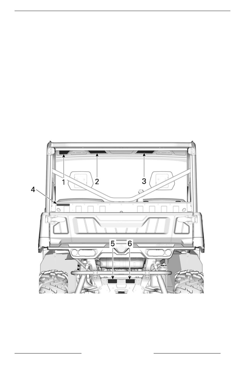
Safety Labels
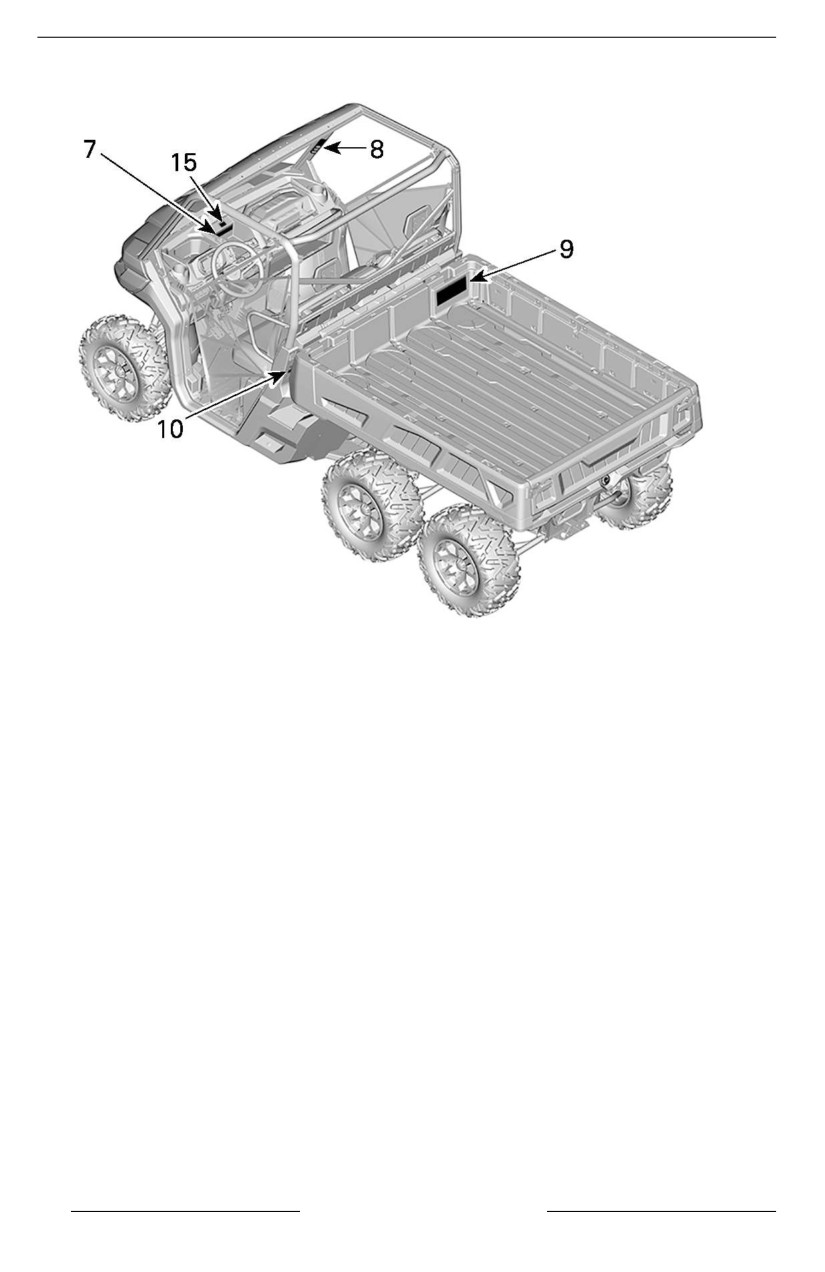
Read and understand all the safety labels on your vehicle.
These labels are affixed to the vehicle for the safety of the operator, passengers
or bystanders.
The following labels are on your vehicle, and they should be considered perma-
nent parts of the vehicle. They need to be clean and visible at all times. If missing
or damaged, they need to be replaced. Safety labels are free of charge. See an
authorized Can-Am Off-road dealer.
Upon replacement of parts that have warnings on them, make sure to order (free
of charge) the applicable safety warnings if not already installed on the replace-
ment part.
NOTE:
In the event of any discrepancy between this guide and the vehicle, the safety la-
bels on the vehicle have precedence over the labels in this guide.
SAFETY INFORMATION
43
IMPORTANT ON-PRODUCT LABELS(CANADA/UNITED STATES)
44
SAFETY INFORMATION
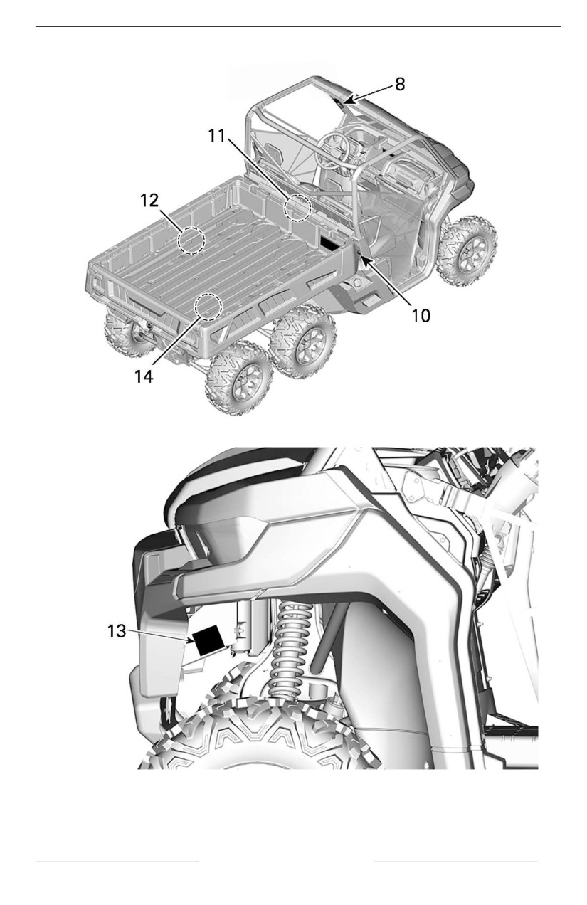
IMPORTANT ON-PRODUCT LABELS(CANADA/UNITED STATES)
SAFETY INFORMATION
45
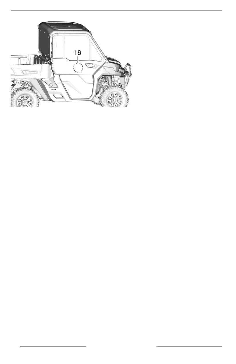
IMPORTANT ON-PRODUCT LABELS(CANADA/UNITED STATES)
1. General warning
2. General operating warning
3. Passenger warning
4. Pulling a load using the cage
5. Pulling a trailer
6. Towing and tongue weight
7.
4WD/6WD selection
8. Rollover
9. Tire pressure and maximum load
10. Cargo box pinch point
11. Coolant hot
12. Cargo box retaining tool
13. Winch installation
14. Exhaust
15. Off-road usage
16. Door warning
46
SAFETY INFORMATION
IMPORTANT ON-PRODUCT LABELS(CANADA/UNITED STATES)
General Warning Labell
Models Without CAB
R
Be Sure Riders Pay Attention and Plan Ahead
If you think or feel the vehicle may tip or roll, reduce your risk of injury :
Require Proper Use of Your Vehicle - Do your part to prevent injuries:
occupants.
Read and understand all safety labels, locate and read operator's
guide and watch the safety video using the QR code link or visit
Can-am web site before operation.
Models With CAB
SAFETY INFORMATION
47
IMPORTANT ON-PRODUCT LABELS(CANADA/UNITED STATES)
Generall Operating Warniing Label
Models Without CAB
Be Prepared
• Fasten seat belts and make sure nets or doors are securely latched in place.
Stay completely inside the vehicle.
Drive Responsibly
Avoid loss of control and rollovers:
stop.
changes in traction and terrain.
Avoid paved surfaces.
Models With CAB
Improper Use of O -Highway Vehicles Can Cause
Severe Injury or Death
Be Prepared
• Fasten seat belts and make sure nets or doors are securely latched in place.
• Wear an approved helmet and protective gear.
• Each rider must be able to sit with back against seat, foot at on the oor or
on footrest, and hands on steering wheel or handholds. Stay completely inside
the vehicle.
Drive Responsibly
Avoid loss of control and rollovers:
• Avoid abrupt maneuvers, sideways sliding, skidding or !shtailing, and never do
donuts.
• Avoid hard acceleration when turning, even from a stop.
• Slow down before entering a turn.
• Plan for hills, rough terrain, ruts, and other changes in traction and terrain.
Avoid paved surfaces.
• Avoid side hilling (riding across slopes).
48
SAFETY INFORMATION
IMPORTANT ON-PRODUCT LABELS(CANADA/UNITED STATES)
Passenger Warning Labell
Models Without CAB
PASSENGER(S)
Improper Use of this Vehicle Can Cause Severe Injury or Death
Be Prepared
• Fasten seat belt and make sure net or door is securely latched in place.
• Wear an approved helmet and protective gear.
Y
and hands on handholds. Stay completely inside the vehicle.
Be Sure Riders Pay Attention and Plan Ahead
If you think or feel the vehicle may tip or roll, reduce your risk of injury:
•
• Do not put any part of your body outside of the vehicle for any reason.
PASSENGER QUALIFICATIONS AND RESPONSIBILITIES
• Do not ride after using drugs or alcohol.
• Ask the operator to slow down or stop if you feel uncomfortable when riding.
Models With CAB
PASSENGER(S)
Improper Use of this Vehicle Can Cause Severe Injury or Death
Be Prepared
• Fasten seat belt and make sure net or door is securely latched
in place.
• Wear an approved helmet and protective gear.
You must be able to sit with back against seat, foot at on the oor or on footrest,
and hands on handholds. Stay completely inside the vehicle.
Be Sure Riders Pay Attention and Plan Ahead
If you think or feel the vehicle may tip or roll, reduce your risk of injury:
• Keep a !rm grip on handholds and brace yourself.
• Do not put any part of your body outside of the vehicle for any reason.
PASSENGER QUALIFICATIONS AND RESPONSIBILITIES
• Do not ride after using drugs or alcohol.
• Ask the operator to slow down or stop if you feel uncomfortable when riding.
SAFETY INFORMATION
49
IMPORTANT ON-PRODUCT LABELS(CANADA/UNITED STATES)
Pullliing a Load Using the Cage – Warning Label
NEVER attach to the cage to pull a load.This can cause the vehicle
to tip over. Use only the trailer hitch to pull a load.
8188
Pullliing a Traiiler – Warniing Label
When pulling a trailer:
• Set the shift lever to low gear range (L).
• Reduce your speed and turn gradually.
• Avoid hills and rough terrain.
• Allow more distance to stop.
Towing and Tongue Weiight - Warniing Label
Improperly loading a trailer may cause
loss of control. Evenly balance the load.
MAXIMUM TOWING WEIGHT:
1361 kg
3000 lb
MAXIMUM TONGUE WEIGHT:
136 kg
300 lb
4WD/6WD Sellection — Warniing Label
Put the Shift
Stop the vehicle and
Must use Low Gear if total payload is greater than
Lever to PARK (P)
apply the Brake before
390 kg (860 lb).
before exiting
using the Shift Lever,
vehicle.
the 2WD/4WD Switch
Total payload includes weight of
The vehicle can
operator, passenger, cargo, accessories
roll if not in PARK.
Switch.
and trailer tongue weight if applicable.
8126
50
SAFETY INFORMATION

IMPORTANT ON-PRODUCT LABELS(CANADA/UNITED STATES)
Rolllover — Warning Labells
LH side
RH Side
Be prepared in case of
Be prepared in case of
rollover
rollover
If the vehicle rolls over,
If the vehicle rolls over,
any part of your body
any part of your body
(such as arms, legs, or
(such as arms, legs, or
head) outside of the
head) outside of the
cockpit can be crushed
cockpit can be crushed
by the cage or other
by the cage or other
parts of the vehicle.
parts of the vehicle.
Fasten seat belt and
Fasten seat belt and
make sure net and/or
make sure net and/or
door is securely latched
door is securely latched
in place to help you
in place to help you
avoid sticking out arms
avoid sticking out arms
or legs.
or legs.
hold the
hold the
cage while riding.
cage while riding.
try to stop
try to stop
a rollover using
a rollover using
your arm or leg.
your arm or leg.
9028
9030
SAFETY INFORMATION
51

IMPORTANT ON-PRODUCT LABELS(CANADA/UNITED STATES)
Tiire Pressure and Maxiimum Load – Warning Labell
WARNING
NEVER carry passenger in cargo box or on gate.
Improper tire pressure or overloading can cause loss of control.
NEVER place gasoline container inside cargo box
Loss of control can result in severe injury or death.
when filling it. This can lead to an explosion.
An underinflated tire can come off the rim.
NEVER exceed the vehicle load capacity (see table),
To reduce the risk of loss of control or loss of load:
including weight of operator, passenger, cargo,
When loading cargo:
When carrying a load:
accessories and trailer tongue weight if applicable.
Position cargo towards
Reduce your speed
NEVER exceed REAR LOAD CAPACITY (Refer to label
front and center ans as
and turn gradually.
below), evenly distributed
low as possible.
Avoid hills and rough terrain.
(including trailer tongue weight if applicable).
Latch tail gate.
Allow more distance to stop.
ALWAYS secure the load.
DEFENDER
6 X 6
PRO
PACKAGE
XT
LTD
OTHERS
LTD
OTHERS
COLD TIRE
FRONT:
kPa
(psi)
124 ( 18 )
103 ( 15 )
110 ( 16 )
138 ( 20 )
138 ( 20 )
PRESSURE
REAR:
kPa
(psi)
124 ( 18 )
103 ( 15 )
110 ( 16 )
145 ( 21 )
152 ( 22 )
MAX LOAD CAPACITY:
kg
( lb )
---
545 (1200)
---
600 ( 1320 )
712 ( 1570 )
CALIFORNIA
MAXIMUM CARGO LOAD:
kg
( lb )
---
272 (600)
---
272 ( 600 )
272 ( 600 )
MAX LOAD CAPACITY:
kg
( lb )
712 ( 1570 )
545 ( 1200 )
771 ( 1700 )
600 ( 1320 )
712 ( 1570 )
OTHERS
MAXIMUM CARGO LOAD: kg ( lb )
454 ( 1000 )
454 ( 1000 )
454 ( 1000 )
454 ( 1000 )
454 ( 1000 )
Refer to your Operator’s Guide for more information about cargo box use.
Cargo Box Pinch Poiint - Warning Labell
Pinch point. Keep
clear when lowering
cargo box.
52
SAFETY INFORMATION

IMPORTANT ON-PRODUCT LABELS(CANADA/UNITED STATES)
Coolant Hot - Warniing Label
WARNING
Do not open when HOT.
Cargo Box Retaining Tool – Warning Label
To reduce the risk of severe injuries, you must use
the designated BRP tool to secure the platform
when you need to disconnect the attachment
from the holding cylinder.
Refer to the shop manual for further informations.
SAFETY INFORMATION
53

IMPORTANT ON-PRODUCT LABELS(CANADA/UNITED STATES)
Winch Installlation - Warniing Label
WARNING
Always use the battery post to
ground the winch. Doing
otherwise may induce an
undesired power steering signal
resulting in an unintended steering
input. In certain circumstances,
some unintended steering input
could lead to a loss of vehicle
control increasing the
risk of a crash.
Off–Road Usage – Warniing Labell
intended for use on public roads
Ce véhicule est conçu pour un
usage hors route et n'est pas
destiné aux voies publiques
7881
54
SAFETY INFORMATION

IMPORTANT ON-PRODUCT LABELS(CANADA/UNITED STATES)
Exhaust — Hot Part Pictogram
CAUTION
Do not touch when hot.
SAFETY INFORMATION
55

IMPORTANT ON-PRODUCT LABELS(CANADA/UNITED STATES)
Door Warning Labell
WARNING
Do NOT put your arm outside of the vehiclle, there iis a risk of SEVERE
INJURY.
LH Side
RH Side
8036
8944
56
SAFETY INFORMATION
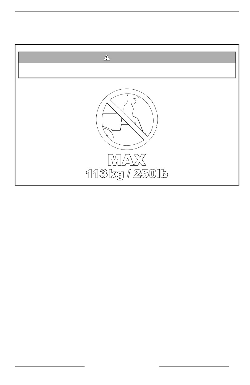
IMPORTANT ON-PRODUCT LABELS(CANADA/UNITED STATES)
Molded Safety Pictogram
Molded Taillgate Piictogram
WARNING
Never carry passengers iin cargo box or on taiilgate. Max weiight on taiil-
gate during lloadiing iis 113 kg (250 lb)
SAFETY INFORMATION
57
IMPORTANT ON-PRODUCT LABELS(CANADA/UNITED STATES)
Compliance HangTag
Caliifornia Proposition 65 Warniing - Hang Tag
. Operating, servicing and
WARNING
maintaining an off-road vehicle can expose
you to chemicals including engine exhaust,
carbon monoxide, phthalates, and lead,
which are known to the State of California
to cause cancer and birth defects or other
reproductive harm.
To minimize exposure, avoid breathing
exhaust, do not idle the engine except as
necessary, service your vehicle in a
well-ventilated area and wear gloves or wash
your hands frequently when servicing your
vehicle.
For more information go to
passenger-vehicle
704906872
58
SAFETY INFORMATION
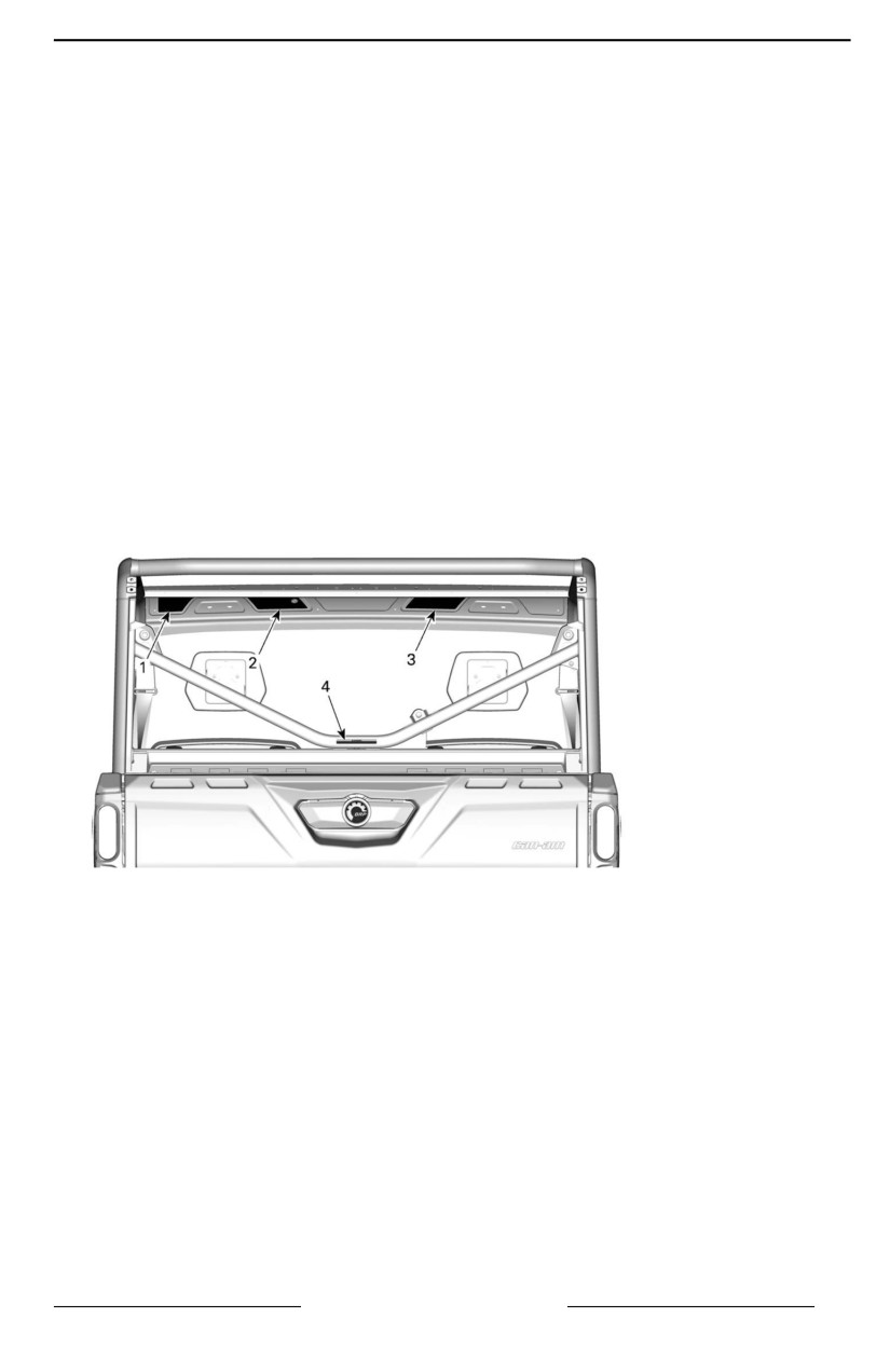
IMPORTANT ON-PRODUCT LABELS (ALL
COUNTRIES EXCEPT CANADA/UNITED STATES)
Safety Pictogram
Read and understand all the safety labels on your vehicle.
These labels are affixed to the vehicle for the safety of the operator, passengers
or bystanders.
The following labels are on your vehicle, and they should be considered perma-
nent parts of the vehicle. They need to be clean and visible at all times. If missing
or damaged, they need to be replaced. Safety labels are free of charge. See an
authorized Can-Am Off-road dealer.
Upon replacement of parts that have warnings on them, make sure to order (free
of charge) the applicable safety warnings if not already installed on the replace-
ment part.
NOTE:
In the event of any discrepancy between this guide and the vehicle, the safety la-
bels on the vehicle have precedence over the labels in this guide.
TYPICAL
SAFETY INFORMATION
59
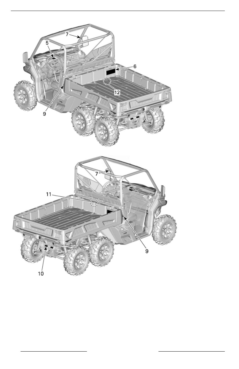
IMPORTANT ON-PRODUCT LABELS (ALL COUNTRIES EXCEPT CANADA/UNITED STATES)
60
SAFETY INFORMATION
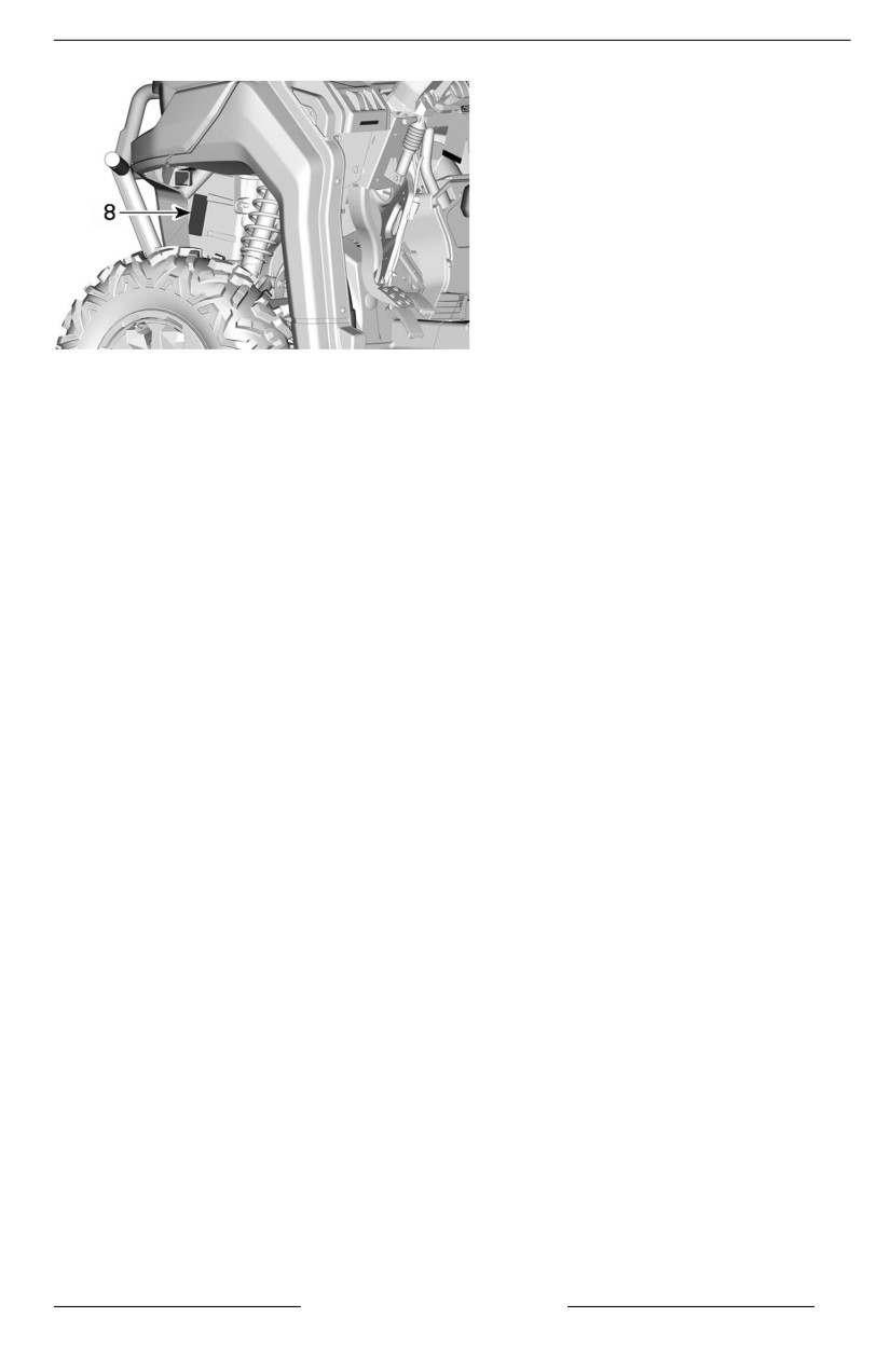
IMPORTANT ON-PRODUCT LABELS (ALL COUNTRIES EXCEPT CANADA/UNITED STATES)
1. General warning
2. General operating warning
3. Passenger warning
4. Pulling a load using the cage
5.
4WD/6WD selection
6. Tire pressure and maximum load
7. Rollover
8. Winch installation
9. Cargo box pinch point
10. Towing and tongue weight
11. Coolant hot
12. Exhaust
SAFETY INFORMATION
61

IMPORTANT ON-PRODUCT LABELS (ALL COUNTRIES EXCEPT CANADA/UNITED STATES)
General Warning Pictogram
WARNING
– Make sure operators are 16 or ollder wiith a valiid driiver''s license.
– Do not exceed seating capaciity: 3 occupants.
– Do not let peoplle driive or riide after usiing alcohol or drugs.
– Avoid lloss of controll and rolllovers:
– Avoiid abrupt maneuvers, sideways slliding, skiiddiing or fishtaiil-
i
ing, and never do donuts.
– Avoiid hard acceleration when turniing, even from a stop.
– Slow down before entering a turn.
– Plan for hiillls, rough terrain, ruts, and other changes in tractiion
and terraiin.
– Avoiid paved surfaces.
– Avoiid siide hiillling (ridiing across slopes).
– Rolllovers have caused severe iinjjuries and death, even on fllat, open
areas.
– Do not alllow operatiion on publlic roads (unless designated for off--
highway vehiicle access) – collliisions wiith cars and trucks can occur.
– Watch the safety viideo using the QR code liink or visiit Can-am web
site before operation.
16+
3
max
7949
62
SAFETY INFORMATION
IMPORTANT ON-PRODUCT LABELS (ALL COUNTRIES EXCEPT CANADA/UNITED STATES)
Operator Warning Pictogram
WARNING
– Read and understand alll safety labells, llocate and read operator''s
guiide.
– Always wear an approved hellmet and protective gear.
– Fasten seat bellts and make sure net or door iis securelly latched in
pllace.
– Always wear ear protection.
– Each riider must be ablle to sit with back agaiinst seat, feet fllat on the
flloor or on footrest, and hands on steeriing wheell or handholds.
– If you think or feell the vehiicle may tiip or rolll, reduce your riisk of in-
jury : Keep a firm griip on the steering wheel or handhollds and brace
yoursellf. Do not put any part of your body outsiide of the vehicle for
any reason.
– Always stay completelly inside the vehiicle.
7947
SAFETY INFORMATION
63

IMPORTANT ON-PRODUCT LABELS (ALL COUNTRIES EXCEPT CANADA/UNITED STATES)
Passenger Warning Pictogram
WARNING
– Allways wear an approved helmet and protectiive gear.
– Allways wear ear protectiion.
– Fasten seat belts, and make sure net or door iis securelly latched in
place.
– Each rider must be able to siit wiith back against seat, feet flat on the
floor or on footrest, and hands on handhollds.
– If you thiink or feel the vehicle may tip or rolll, reduce your risk of
i
injjury:
– Keep a firm griip on the steering wheel or handhollds and brace
yoursellf.
– Do not put any part of your body outsiide of the vehiclle for any
reason.
– Allways stay complletely iinsiide the vehicle.
– Do not let peoplle driive or riide after usiing alcohol or drugs.
7951
64
SAFETY INFORMATION

IMPORTANT ON-PRODUCT LABELS (ALL COUNTRIES EXCEPT CANADA/UNITED STATES)
Tire Pressure and Maximum Load – Warning Pictogram
WARNING
– Locate and read operator''s guiide. Improper tire pressure or over-
loadiing can cause loss of control, resullting in SEVERE INJURY or
DEATH.
– Always maiintain proper tiire pressure as shown.
– NEVER exceed the vehiiclle load capaciity, iincludiing weight of opera-
tor, passenger, cargo, accessories and trailler tongue weight if
appliicablle.
– Do not overload cargo box.
– NEVER place gasoliine contaiiner iinsiide cargo box when fillliing iit.
This can llead to an explosion.
– NEVER carry passenger iin cargo box or on taiilgate.
227 (500)
227 (500)
kg (lb)
kPa (psi)
< kg (lb)
< kg (lb)
97 (14)
124 (18)
97 (14)
228 (33)
3x
680 (1500)
454 (1000)
XMR
97 (14)
124 (18)
97 (14)
179 (26)
390 (860)
390 (860)
kg (lb)
kPa (psi)
3x
PRO
138 (20)
152 (22)
172 (25)
255 (37)
712 (1570)
454 (1000)
3x
6 x 6
103 (15)
103 (15)
110 (16)
110 (16)
771 (1700)
454 (1000)
6x
152 (22)
165 (24)
165 (24)
234 (34)
680 (1500)
454 (1000)
EN
SAFETY INFORMATION
65

IMPORTANT ON-PRODUCT LABELS (ALL COUNTRIES EXCEPT CANADA/UNITED STATES)
Rollover – Warning Labels
WARNING
– Never try to stop a rolllover using your arm or lleg.
– Never hold the cage whille ridiing.
– Fasten seat belts and make sure net or door is securely latched iin
place.
LH side
RH Side
LH
RH
66
SAFETY INFORMATION

IMPORTANT ON-PRODUCT LABELS (ALL COUNTRIES EXCEPT CANADA/UNITED STATES)
4WD/6WD Selection – Warning Pictogram
WARNING
– Stop the vehiclle and applly the brake before using the shift lever and
the 4WD/6WD swiitch.
– When the weight of occupant(s), cargo and tongue is above 390 kg
(860 llb), set the shiift llever to low gear range (L).
– Put the shiift llever to PARK (P) before exiiting vehiclle. The vehiicle
can rolll if not iin PARK.
!
STOP
> 390 kg (860 lb)
!
STOP
L
8894
Winch Installation - Warning Label
WARNING
– Never use the frame near this llocation to ground any electriicall com-
ponent such as a wiinch.
– When in use, the ellectrical component may induce an undesired
power steering signall resulltiing in an uniintended steeriing input.
– In certaiin ciircumstances, some uniintended steeriing input could lead
to a lloss of vehicle control iincreasing the riisk of seriious INJURY or
DEATH.
7689
SAFETY INFORMATION
67

IMPORTANT ON-PRODUCT LABELS (ALL COUNTRIES EXCEPT CANADA/UNITED STATES)
Cargo Box Pinch Point - Warning Label
WARNING
– Piinch point. Keep cllear when lloweriing cargo box.
7956
Pulling a Load Using the Cage – Warning Label
WARNING
– NEVER attach to the cage to pulll a lload. This can cause the vehicle
to tiip over. Use only the trailler hiitch or recovery hook to pulll a load.
68
SAFETY INFORMATION

IMPORTANT ON-PRODUCT LABELS (ALL COUNTRIES EXCEPT CANADA/UNITED STATES)
Towing and Tongue Weight - Warning Pictogram
WARNING
– MAXIMUM towiing capaciity: 1 361 kg (3,000 lb)
– MAXIMUM tongue weiight: 136 kg (300 llb)
– When pullliing a trailler, set the shift lever to low gear range (L).
– Reduce your speed and turn graduallly.
< 1361 kg (3000 lb) 13347 N
< 136 kg (300 lb) 1334 N
Cargo Box Retaining Tool – Warning Label
WARNING
– To reduce the risk of severe iinjuries, you must use the desiignated
BRP tooll to secure the pllatform when you need to diisconnect the at-
tachment from the holdiing cyliinder.
– Refer to the shop manuall for further iinformations.
SAFETY INFORMATION
69
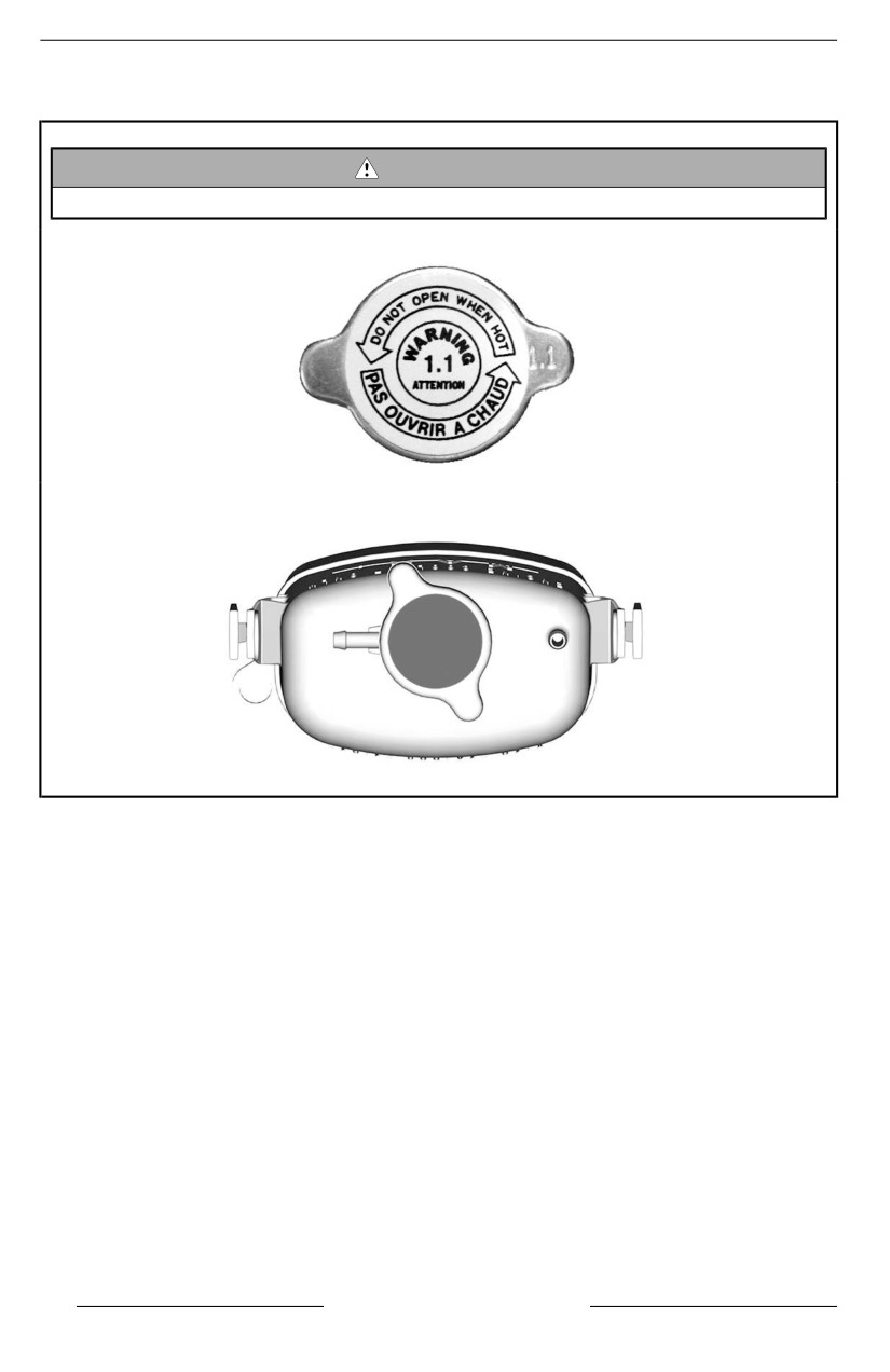
IMPORTANT ON-PRODUCT LABELS (ALL COUNTRIES EXCEPT CANADA/UNITED STATES)
Coolant Hot - Warning Label
WARNING
Do not open when HOT.
70
SAFETY INFORMATION

IMPORTANT ON-PRODUCT LABELS (ALL COUNTRIES EXCEPT CANADA/UNITED STATES)
Exhaust – Hot Part Pictogram
CAUTION
Do not touch when hot.
Cool Starting - Warning Label
This label is located in the front service compartment.
!"#$% '()*!+,-. "/) +,1",/!+#/,
2%/#4!56,9
$/,': ;)4, 1);#$ 30 °= ;,
*!/!;+)/#,+$.. ?#@;29 !(!/)9;:9 A!"#$%
'()*!+,-. ;, "/,'#$12+/,;.
8730
IN EURASIAN UNION ONLY
SAFETY INFORMATION
71
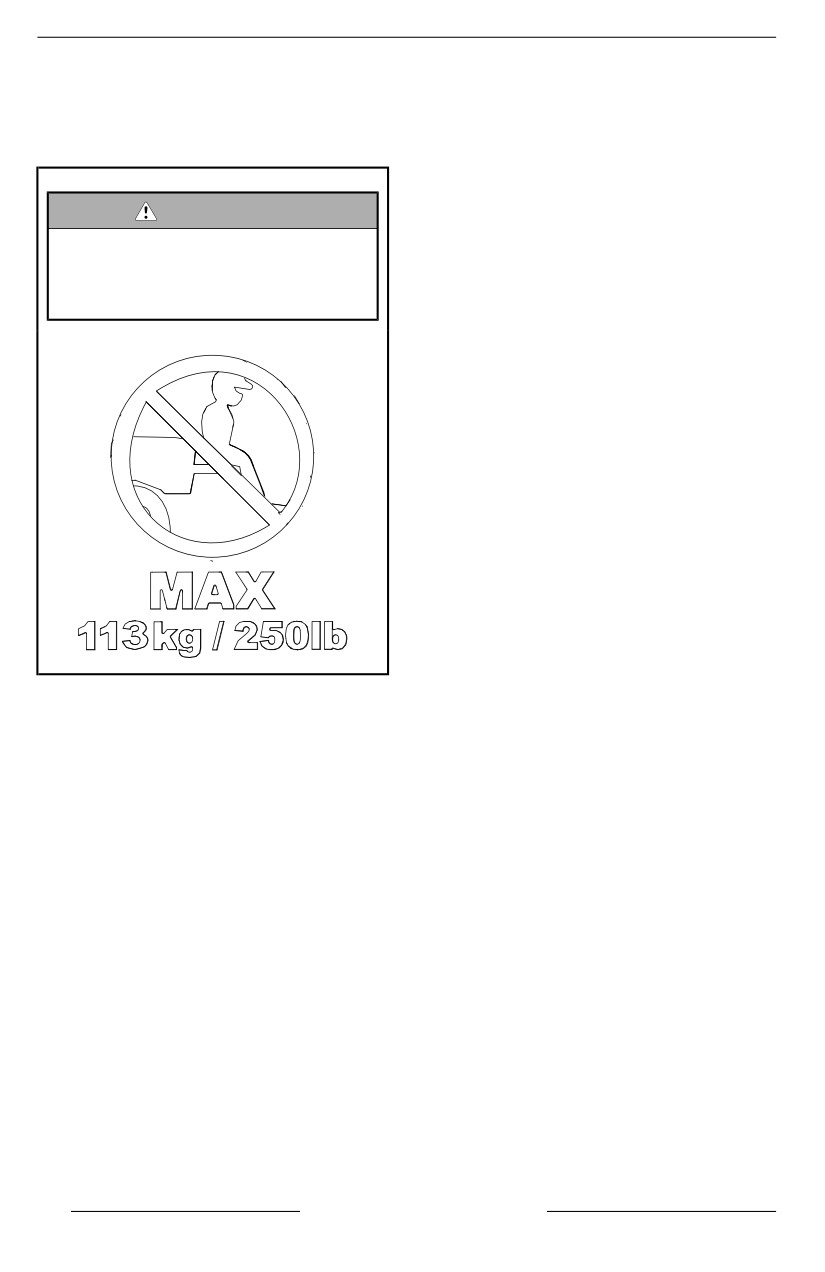
IMPORTANT ON-PRODUCT LABELS (ALL COUNTRIES EXCEPT CANADA/UNITED STATES)
Molded Safety Pictogram
Mollded Taiilgate Pictogram
WARNING
Never carry passengers in car-
go box or on taillgate. Max
weiight on taiilgate during lload-
ing is 113 kg (250 lb)
72
SAFETY INFORMATION
REPORTING SAFETY DEFECTS
In Canada, if you believe that your vehicle has a defect which could cause a
crash or could cause injury or death, you should immediately inform Transport
Canada in addition to notifying Bombardier Recreational Products Inc.
If Transport Canada receives similar complaints, it may open an investigation,
and if it finds that a safety defect exists in a group of vehicles, it may order a re-
call and remedy campaign. However, Transport Canada cannot become involved
in any individual problems between you, your dealer or Bombardier Recreational
Products Inc.
To contact Transport Canada:
819-994-3328 (Gatineau-Ottawa area or internationally)
Toll free : 1 800-333-0510 (in Canada)
Transport Canada - ASFAD
330 Sparks Street
Ottawa, ON
K1A 0N5
SAFETY INFORMATION
73
SAFETY INFORMATION
This page is intentionally blank
74
SAFETY INFORMATION
VEHICLE INFORMATION
75
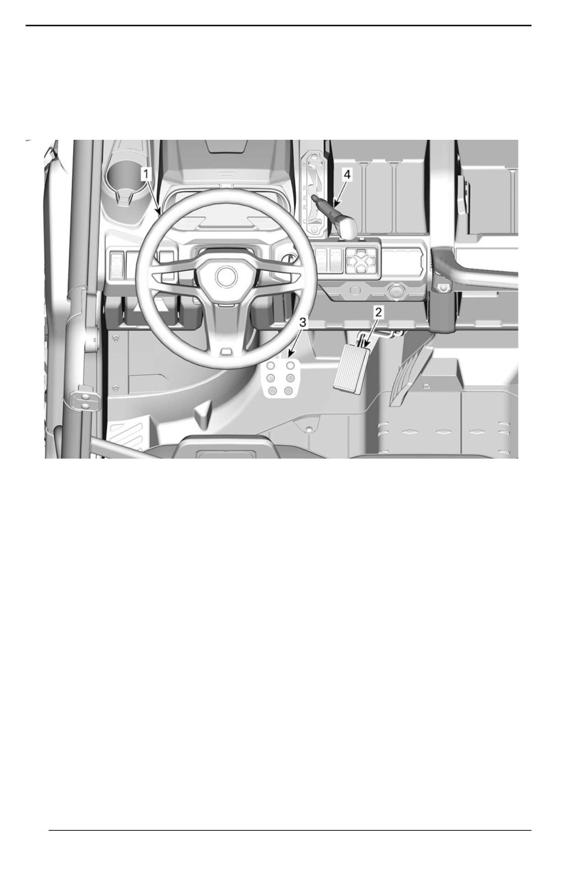
PRIMARY CONTROLS
It is important to know the location and
NOTE:
operation of all controls, and to devel-
Some vehicle safety labels are not
op and practice smooth and coordi-
shown on illustrations. For information
nated use of them.
on vehicle safety labels, refer to Im-
portant on-product labels.
1. Steering wheel
2. Accelerator pedal
3. Brake pedal
4. Shifter
76
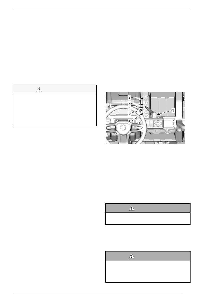
PRIMARY CONTROLS
Steering Wheel
To decrease vehicle speed or to stop
vehicle, press down the brake pedal
The steering wheel is located in front
with your right foot.
of the driver's seat.
The brake pedal is spring loaded and
The steering wheel steers the vehicle
should return to rest position when not
to the left or right.
pressed.
Turn the steering wheel in the direc-
tion you want to go.
Shift Lever
The shift lever is located on the upper
Grip the steering wheel with both
console to the right of steering wheel.
hands, without having thumbs rolled
around the steering wheel.
The shift lever is used to change the
gearbox position.
CAUTION
Under rough traill condiitiions or
when crossing an obstaclle, the
steeriing wheell coulld suddenlly
j
jerk on one side, causing hand or
wrist injuriies iif the thumbs are
rollled around the steering wheell.
A dynamic power steering (DPS) re-
duces the effort to turn the steering
wheel.
TYPICAL
1. Shift lever
Accelerator Pedal
2. Park
The accelerator pedal is located on
3. Reverse
the right side of the brake pedal.
4. Neutral
5. High range (forward)
The accelerator pedal controls the en-
6. Low range (forward)
gine speed.
The vehicle must be
stopped
and
To increase or maintain vehicle
brakes applied prior to selecting any
speed, press on the accelerator pedal
gear.
with your right foot.
To decrease vehicle speed, release
WARNING
the accelerator pedal.
Thiis gearbox iis not desiigned to
shift whiile vehiicle is moving.
The accelerator pedal is spring loaded
and should return to rest position (idle)
when not pressed.
Park
The park position locks the gearbox to
Brake Pedal
help prevent vehicle movement.
The brake pedal is located on the left
side of the accelerator pedal.
WARNING
The brake pedal function is to slow
Always use the PARK (P) posiitiion
down or stop the vehicle.
when the vehiiclle is not iin opera-
tiion. The vehiiclle can rolll if the
shift lever is not set to P (PARK).
77
PRIMARY CONTROLS
Reverse
The reverse position allows the ve-
hicle to go backwards.
Depending upon your particular ve-
hicle configuration, a back-up alarm
may be equipped on the vehicle. It
goes on automatically when the re-
verse gear is selected.
NOTE:
In reverse operation, the engine RPM
is limited thus limiting the vehicle re-
verse speed.
WARNING
When driiving downhilll iin reverse,
gravity can iincrease the vehicle
speed above safe reverse speed.
Neutral
The neutral position disengages the
gearbox.
High Range (Forward)
This position selects the high speed
range of the gearbox. It is the normal
driving speed range. It allows the ve-
hicle to reach its maximum speed.
Low Range (Forward)
This position selects the low speed
range of the gearbox. It allows the ve-
hicle to move slowly with maximum
torque at the wheels.
NOTICE
Use the llow speed range to pulll a
trailer, carry heavy cargo, go over
obstacles or drive uphiilll and
downhiilll.
78
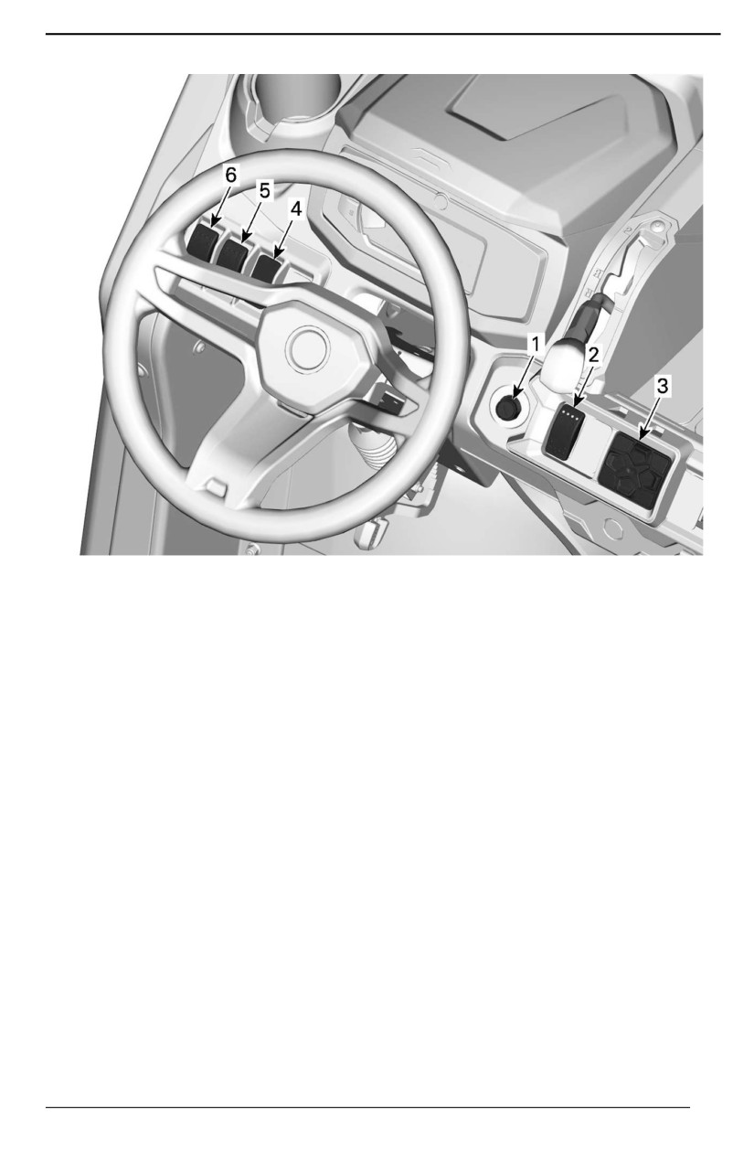
SECONDARY CONTROLS
MODELS WITHOUT CAB
1. Ignition switch
2.
4WD/6WD switch
3. Keypad
4. Power-tilt bed switch
5. Winch switch
6. Headlight dimmer switch
79
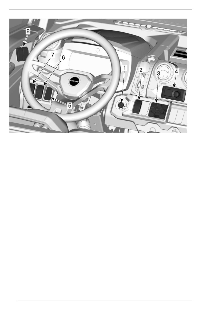
SECONDARY CONTROLS
MODELS WITH CAB
1. Ignition switch
2.
4WD/6WD switch and Smart Lok (if equipped)
3. Keypad
4. Climate control
5. Power-tilt bed switch
6. Winch switch
7. Headlight dimmer switch
8. Power windows switches
80
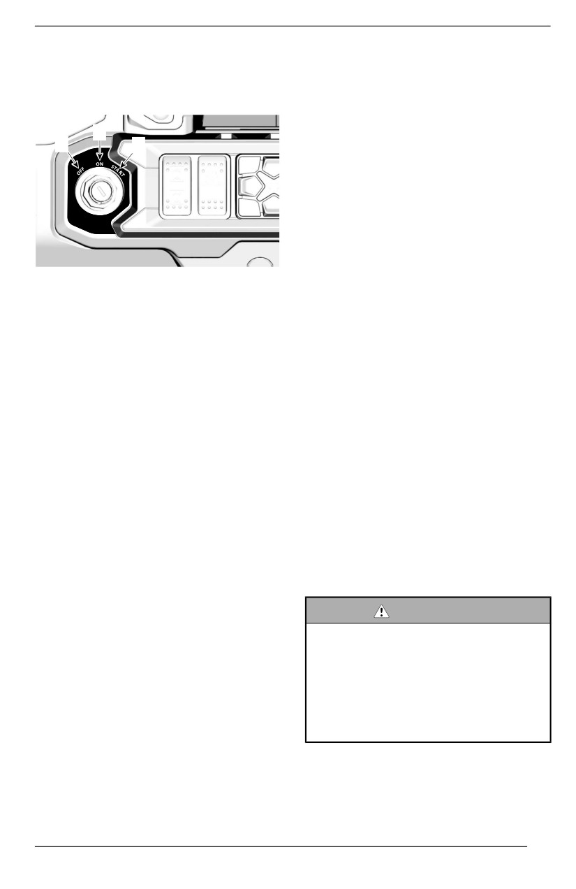
SECONDARY CONTROLS
Ignition Switch and Keys
Keys
The ignition switch is located on the
Basic Key
upper console area.
The vehicle is delivered with 2 basic
key.
2
1
3
Those 2 mechanical keys do not have
speed or torque restrictions.
D.E.S.S. Key (Avaiilable as an
optiion)
For all D.E.S.S. related option, see an
authorized Can-Am Off-road dealer
for information.
Digiitallly Encoded Securiity System
1. OFF
(D.E.S.S.)
2. ON
3. START
The ignition keys contain an electronic
circuit that gives it a unique electronic
OFF
serial number.
The key can be inserted or removed in
The D. E. S. S. system reads the key
this position only.
code and allows engine starting for
In OFF position, the electrical system
keys it recognizes.
of the vehicle is disabled.
This vehicle can be operated using 3
The engine is shut down by turning
different types of key programming:
the ignition switch to OFF position.
- Work
- Normal
ON
- Performance
When the key is turned in this position,
Refer to your dealer for complete
the electrical system of the vehicle is
information.
activated.
NOTE:
The gauge should wake-up.
Additional keys are available from
The vehicle lights are turned on.
your dealer as an accessory.
The engine can be started.
WARNING
START
Rolllovers, tiipovers, colllisions and
l
loss of control resullting in serious
This position starts the engine.
i
injury or death are possiible with
NOTE:
the performance or normal key.
If the ignition switch is left ON for more
Using the normal key is not a sub-
than 30 minutes, engine will not start
stitute for the operator being pre-
unless ignition switch is turned OFF,
pared, qualiified, and operating
then ON again.
wiith care.
Performance Key
81
SECONDARY CONTROLS
The performance key allows the user
4WD/6WD Switch
to access the full torque of the engine
The 4WD/6WD switch is located on
as well as the top speed of the
the upper console.
vehicle.
This may be useful for riders who pre-
fer crisper throttle response, and for
environments where higher speeds
and greater acceleration are appropri-
ate. For example, in wide-open
straight trails, operators may prefer
the performance key.
Normal Key
The normal key limits the vehicle
speed to 70 km/h (43 MPH) and ap-
plies a torque reduction.
Work key
This switch selects 4 wheel drive, or 6
The work key allows for usage of
wheel drive mode when the vehicle is
100% of maximum engine torque but
stopped.
limits vehicle speed to 40 km/h (25
MPH).
NOTICE
The vehiclle must be stopped to
WARNING
engage or diisengage 4WD/6WD
On steep downhillls, the engine
swiitch.
speed llimiter may not prevent the
Mechanical damage may occur iif
vehicle from accelerating beyond
swiitch is engaged or disengaged
this speed.
whiile driviing.
This key may be useful for riders who
The 6WD mode is engaged when the
prefer more gradual acceleration, or
switch is pushed upwards.
for riding in environments where full
speed and high acceleration are not
The 4WD mode is engaged when the
desirable. For example, in narrow,
switch is pushed downwards. The ve-
winding trails, operators may prefer a
hicle is then rear wheel drive only.
normal key.
2WD/4WD/Front Diff Lock
D.E.S.S. Flexibiiliity
Switch
The D. E. S. S. of your vehicle can be
Modells with Smart-Lok
programmed by your authorized Can--
Am Off-road dealer to accept up to 8
The 2WD/4WD/Front Diff Lock switch
different keys.
is located on the upper console.
If you have more than one D. E. S. S.
equipped your vehicle, each can be
programmed by your authorized Can--
Am Off-road dealer to accept the other
vehicle D.E.S.S. keys.
82
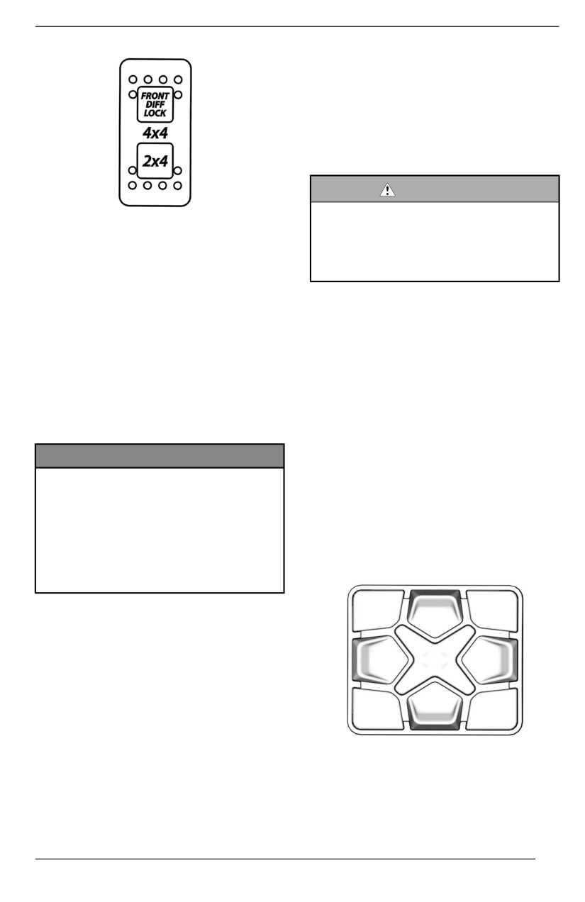
SECONDARY CONTROLS
Smart-Locker, the AUTO pictogram
will lit above the
4x4
logo in the
cluster.
When the front differential is locked,
the effort to turn the steering wheel
might be higher and the response
might be slower.
WARNING
Abruptly changing direction can
cause lloss of controll or injjury.
This switch selects 2 wheel drive or 4
Never engage Front Diff Lock be-
wheel drive mode when the vehicle is
fore entering a turn or when
stopped.
turning.
Once the vehicle 4WD mode is en-
gaged, the front diff lock can be acti-
The front differential is locked and the
vated when the switch is pushed
4WD mode is engaged when the
upwards.
switch is pushed upwards.
The front diff. lock can be activated on
The 4WD mode is engaged when the
the fly, no need to stop the vehicle to
switch is in the middle.
engage. To deactivate, push again on
the switch. When the engine is
The 2WD mode is engaged when the
stopped, the front diff. lock will be
switch is pushed downwards. The ve-
deactivated.
hicle is then rear wheel drive only.
NOTICE
Keypad
The vehiiclle must be stopped to
The keypad is used to navigate
engage or disengage the 2WD/
through various menus and options
4WD switch.
when the
7.6" Digital Display is
Mechaniicall damage may occur if
installed.
swiitch iis engaged or disengaged
whiile driiviing.
The keypad is located on the upper
Allways unllock the front diiff. be-
console.
fore diisengagiing 4WD.
The front differential is fully locked
when the switch is pushed upward. It's
a momentary position. When the front
diff. is locked, the switch light will illu-
minate and a message will appear in
the cluster for 2 seconds to say "DIFF
LOCK". A padlock pictogram will ap-
pear inside the 4x4 logo. The light will
turn off when the differential is un-
locked and a message in the cluster
will appear and show "SMART-LOK",
Climate Controls
meaning that you are back in the auto-
CAB Modells Only
matic mode. For all models with
83
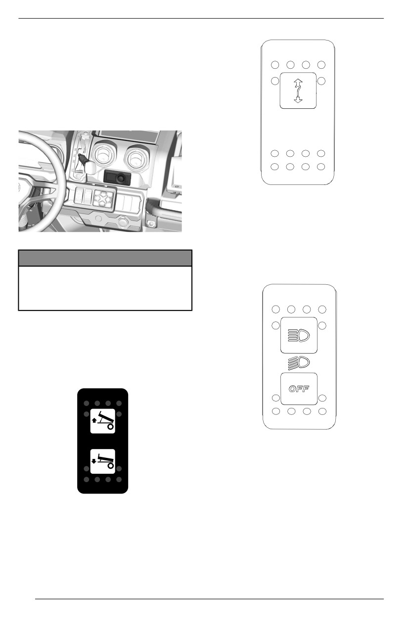
SECONDARY CONTROLS
The climate controls unit are located
in center of the upper console.
They control the flow and the temper-
ature of the air circulated in the
vehicle.
Refer to Climate Control System in
Equipment for operation instructions.
Refer to your Winch Guide included
with your vehicle for proper winch
operation.
A/C EQUIPPED MODELS
Headlight Dimmer Switch
NOTICE
The headlight dimmer switch is lo-
cated on the upper console.
The ellectroniic modulle used to
controll the cliimate controll system
o iis not waterproof nor water
resistant.
Power–tilt Bed Switch
The cargo box can be controlled from
inside the vehicle with the power-tilt
bed control switch located in the upper
console.
This switch is used to select either the
headlights OFF position, low or high
beams.
Power Window Switches (If
Equipped)
Winch Switch
The power window switches are lo-
cated on the door panel. Two switches
The winch can be controlled from in-
on the driver side and one on the pas-
side and outside the vehicle with the
senger side.
winch control switch located in the
upper console.
84
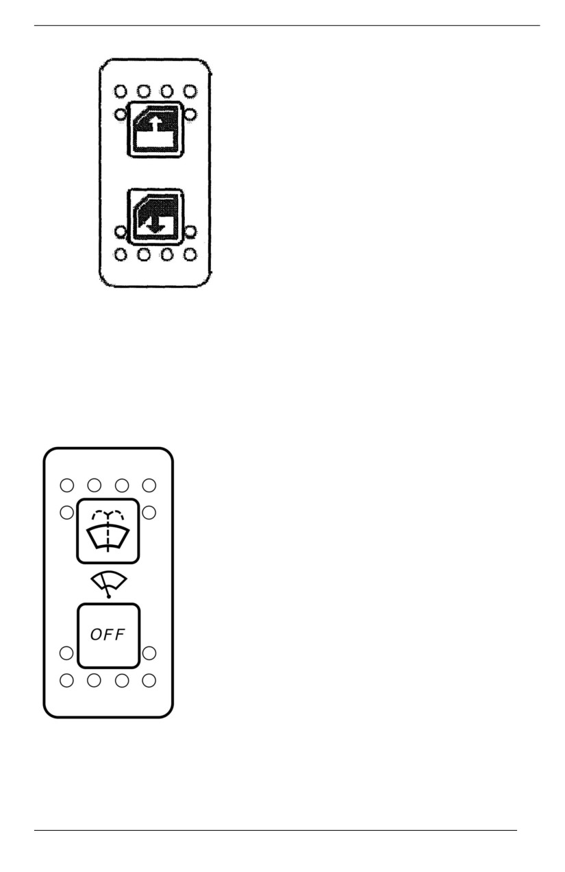
SECONDARY CONTROLS
1. Press the switch to open the
window.
2. Lift the switch to close the window.
Wiper / Windshield Washer
Switch
The wiper / windshield washer switch
is located overhead, to the left of the
central mirror.
This switch is used to select either the
OFF, wipe or wash-and-wipe
positions.
85
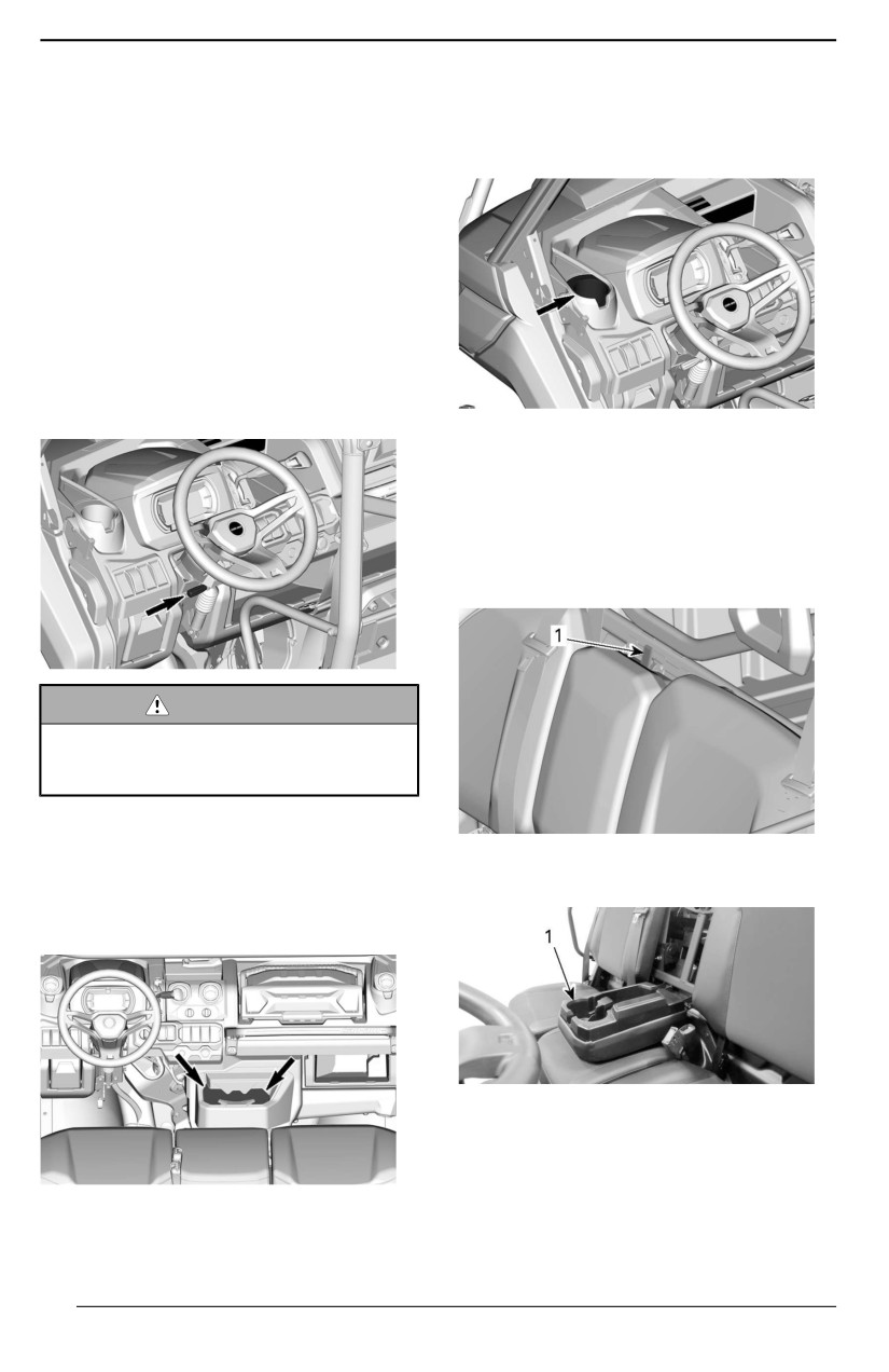
EQUIPMENT
Tilt Steering
Two cup holders are located on each
side of the dash near the side nets at-
The steering wheel height is
tachment points.
adjustable.
Adjust the steering wheel height to
face your chest, not your head.
To adjust steering wheel height:
1. Unlock steering by pulling the tilt
lever toward you.
2. Move steering wheel to the desired
position.
3. Release tilt lever to lock steering
wheel in position.
Alll models
Two additional cup holders are avail-
able on the back of the central pas-
sengers seat backrest.
To access them, lower the seat
backrest.
WARNING
Never adjjust the steeriing wheell
heiight whiile riiding. You may llose
controll.
Cup Holders
TYPICAL
CAB modells
1. Backrest clip locking mechanism
Two cup holders are located on the
central console.
TYPICAL
1. Central passenger backrest cup holder
NOTE:
Alll except CAB models
Do not use cup holders while riding in
rough conditions.
86
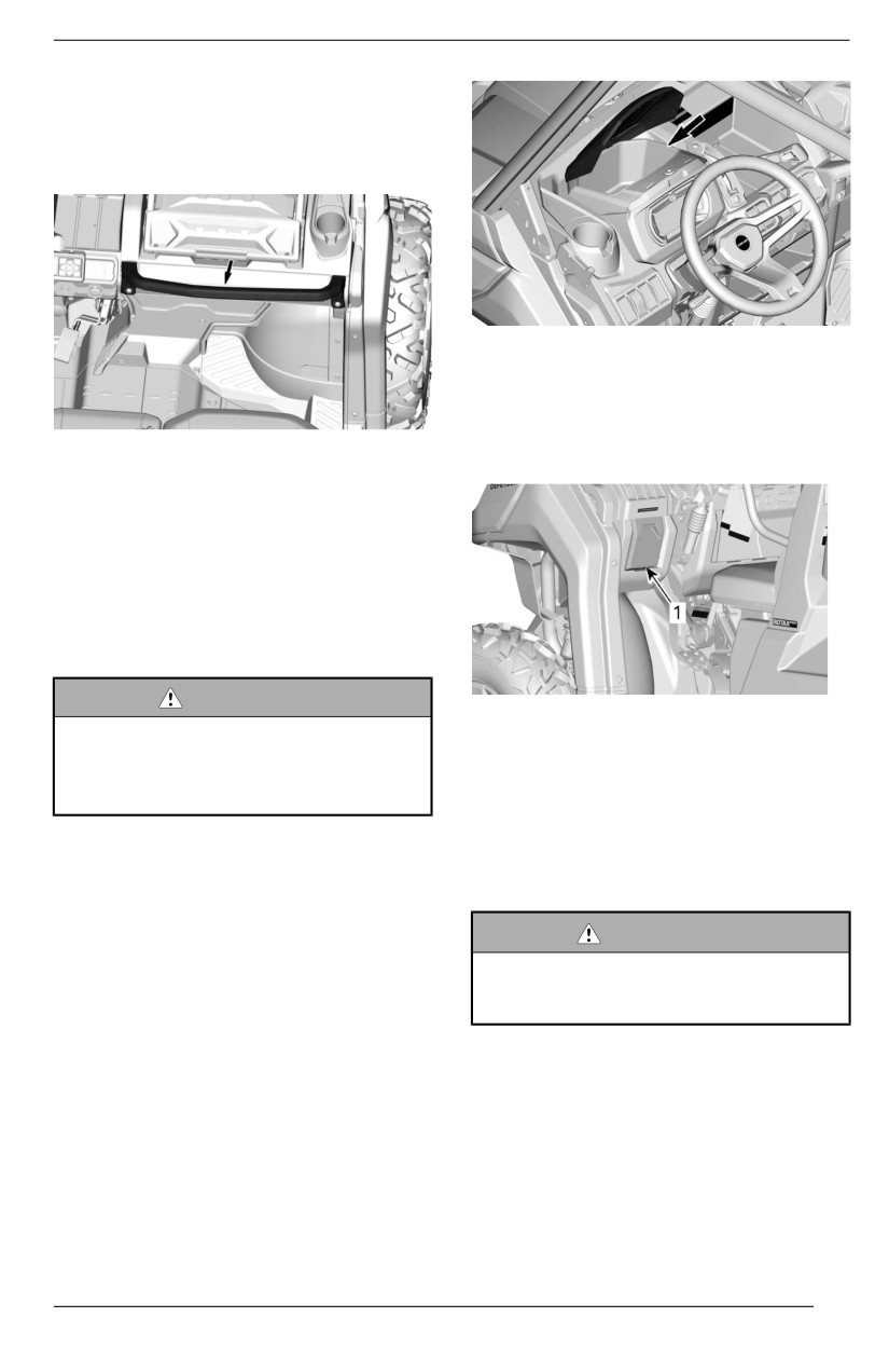
EQUIPMENT
Passengers Handhold
The passengers have access to a
front handhold located in front of their
seats.
Driver Storage Compartment
A small storage compartment is avail-
able on the driver side.
Pull on handle to rotate it open.
Adjust the seat position in order to get
a solid and comfortable grip on the
handholds. Refer to Passenger’s Seat
for adjustment procedure.
Holding the handhold helps the pas-
sengers brace against the movement
of the vehicle and helps keep hands
and body inside the cockpit in the
event of a rollover.
WARNING
TYPICAL
Never use any part of vehiclle
1. Driver storage compartment
cage as handholds. Hands can be
struck by objects outsiide the
Removable Tool Box
cockpit or crushed iin a rollover.
A removable tool box is located on the
upper console in front of the passen-
Storage Compartments
ger’s seat..
The vehicle is equipped with storage
Openiing the Tool Box Lid
compartments designed to carry light
objects.
WARNING
Before ridiing, always make sure
Multifunctiion Gauge Storage
tool box is secured to vehiicle and
Compartment
l
lid iis locked.
A storage compartment is available
above the multifunction gauge.
1. Push the lock downwards and lift
the lid.
87
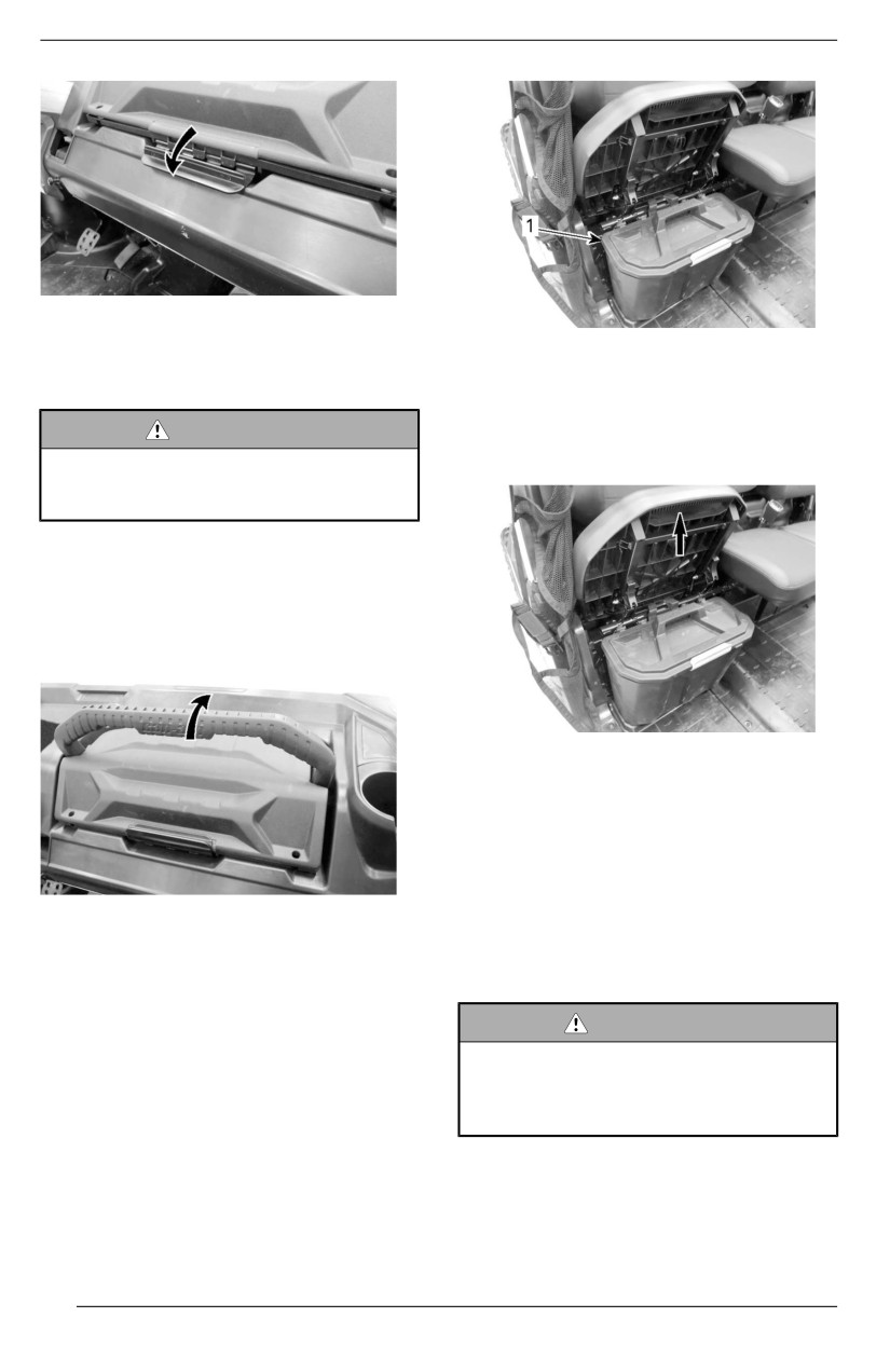
EQUIPMENT
2. To close the lid, lower it and push
the lock upwards.
TYPICAL
1. Under seat storage box
Removiing and Securing the Tool
Box
To remove under seat storage box, lift
WARNING
RH passenger seat and remove under
Before ridiing, always make sure
seat storage box by pulling it upwards.
tool box is secured to vehiicle and
l
lid iis locked.
1. To remove the tool box from the
vehicle, lift its transport handle.
2. To secure the tool box in place, po-
sition it carefully and lower the
transport handle.
TYPICAL
NOTE:
When reinstalling under seat storage
box, make sure to align it properly with
seat tubes and floor emboss so it fits
properly under the seat.
SECURING TOOL BOX IN PLACE
Open Storage Compartments
Under Seat Storage Box
Multiple open storage compartments
A convenient removable under seat
are available in the console.
storage box is available.
WARNING
When ridiing vehicle, make sure
no objject stored in open storage
compartments coulld cause harm
in the event of a rolll over.
88
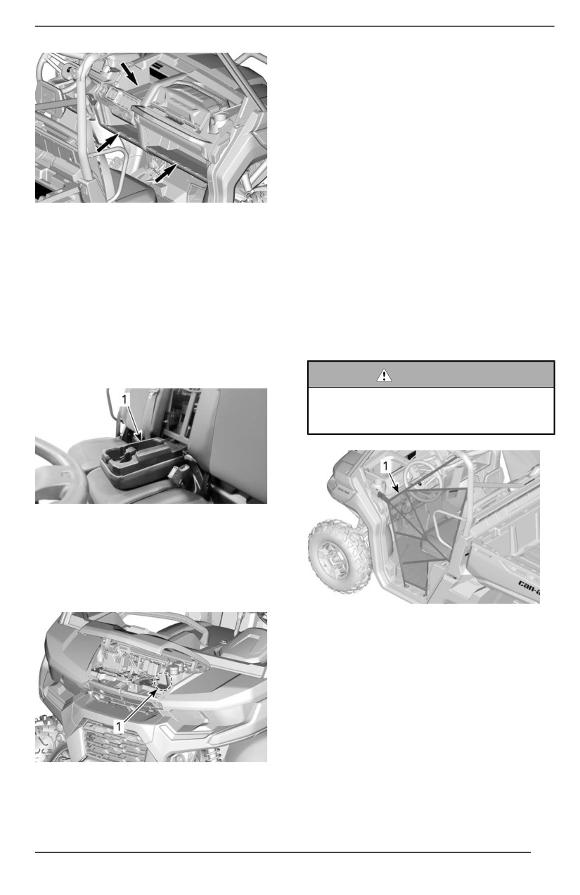
EQUIPMENT
Footrests
The vehicle is equipped with driver
and RH passenger footrests to allow
firmly planting feet on vehicle floor,
which helps to maintain proper body
position while riding.
The footrests help minimize the risk of
leg or foot injury.
Always wear appropriate footwear.
ALL EXCEPT BASE
See Riding Gear.
Central Passenger Backrest
Side Nets
Storage Area
A side net is provided on each side of
When central passenger seat back-
the cockpit to help arms, legs or
rest is pulled down a storage area is
shoulders stay inside the vehicle, thus
available.
reducing the risk of injuries. Side nets
may also keep bushes or other debris
NOTE:
out of the cockpit.
Always empty storage area before
putting central passenger backrest up.
WARNING
Never operate the vehicle unless
both siide nets are iin pllace and
bucklled.
TYPICAL
1. Central passenger backrest storage area
Tool Kit
A tool kit with basic tools is provided.
It is located in the front service center.
1. Side net
Side nets are adjustable and must be
kept as tight as possible.
To adjust side nets proceed as
follows:
1. Secure side net with buckle.
2. Pull on all adjustment straps to
tighten.
1. Tool kit
89
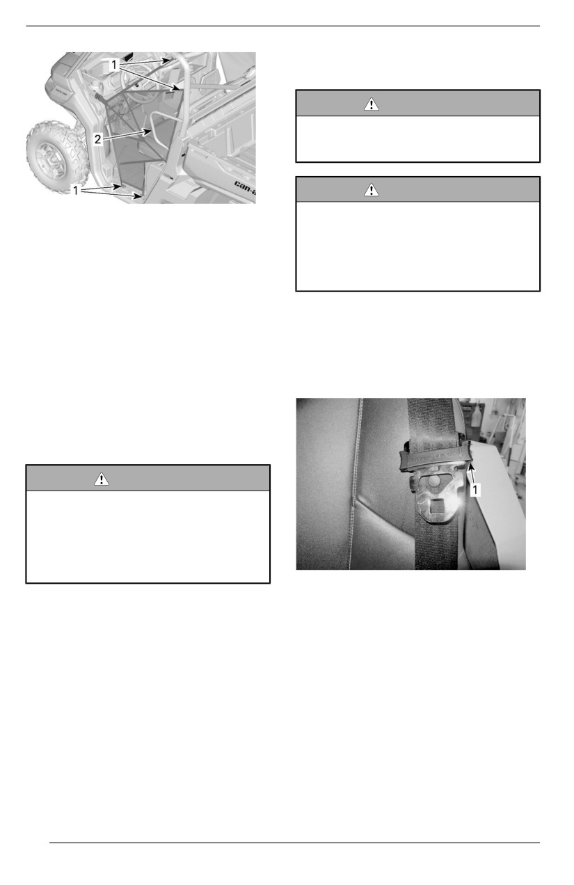
EQUIPMENT
of approximately 20 km/h (12
MPH) on flat ground.
WARNING
The vehiclle may reach hiigher or
lower speed dependiing on
incliines.
WARNING
1. Side net adjustment locations
There is no iindicator llight or mes-
2. Shoulder guard
sage for the passengers seat belt.
The driver is responsiible for the
passenger safety and shoulld en-
Shoulder Guards
sure the passengers bucklle theiir
The vehicle is equipped with shoulder
seat belt.
guards to help restrain the entire body
of driver and passengers inside
Fastening and Adjjusting the Seat
vehicle.
Belt
The seat belt is equipped with a semi--
Seat Belts
cinching tab that locks the lap belt
This vehicle is equipped with 3 points
when the webbing is under tension.
seat belts to help protect driver and
passenger in the event of a collision,
rollover, or tipover. The seat belts can
help keep occupants stay in the pas-
senger compartment.
WARNING
Wear seat belts properly at alll
tiimes.
Seat belts reduce the riisk of injury
i
in case of a crash and hellp to
keep liimbs iinsiide the cockpiit dur-
i
ing a rolllover or any acciidents.
TYPICAL
1. Semi-cinching tab
If driver's seat belt is not fastened
when:
To fasten the seat belt, insert the latch
- The ignition is turned ON
plate into the buckle, then pull the belt
to ensure it is properly fastened.
- The seat belt indicator lamp will
be turned ON.
Adjust the seat belt tightly against
- The multifunction gauge will
your body by pulling the shoulder belt
display the message: SEAT
upwards.
BELT.
- The engine is started and shift lev-
er is moved out of PARK, vehicle
speed will be limited to a maximum
90
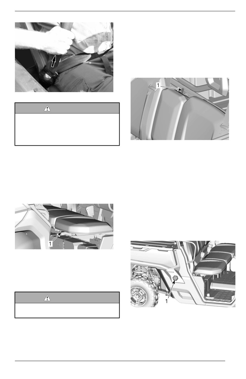
EQUIPMENT
Passenger Seats
The passenger seats are not
adjustable.
The central passenger seat backrest
can be tilted forward for access to cup
holders by releasing the latch located
on top of the backrest.
TYPICAL
WARNING
Wear seat bellt properly. Make
sure iit remaiins securelly fastened
and tiightened against the body.
Make sure it iis not twiisted or
defective.
TYPICAL
1. Backrest clip locking mechanism
To release the seat belt, push on the
red button on the seat belt buckle.
On applicable models, the seats can
be lifted to allow access to removable
Driver''s Seat
under seat storage compartment.
On applicable models, the driver's
To lift seat, pull on front of seat to un-
seat can be adjusted forward and
clip it and lift until it "clips" in the upper
backward.
position.
Fuel Reservoir Cap
The fuel reservoir cap is located on
the right hand side of the vehicle,
under the cargo box release handle.
TYPICAL
1. Adjustment lever
To adjust seat, move the seat lever to
unlock the seat. Release the lever to
lock the seat into desired position.
WARNING
Never adjust the seat posiitiion
TYPICAL
whiile driiviing.
1. Fuel reservoir cap
Refer to Fuel section for information
on fueling procedure and fuel
requirements.
91
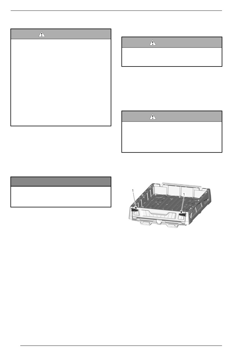
EQUIPMENT
Winch
of 3000 RPM to increase charging
power to the battery.
WARNING
To avoid severe injjury or death or
WARNING
i
important components damages.
Make sure vehiclle is in NEUTRAL
– Never use the wiinch cablle/
(N) before increasing engiine
rope to retaiin a vehicle during
RPM.
traiileriing.
– Never ride with the winch ca-
Cargo Box
ble/rope attached to a load or
another vehiclle.
The vehicle is equipped with a an in-
– Only use the wiinch to hellp a
clinable cargo box. The cargo box
stuck vehicle (snow, mud,
may be used for various types of
etc.).
cargo.
– Allways refer to the winch man-
ufacturer''s instruction before
WARNING
pulliing loads.
To reduce the riisk of loss of con-
troll or loss of lload, use the cargo
Refer to your winch guide included
box only iin accordance with Car-
with your vehicle for proper winch
rying Loads in the safety Informa-
operation.
tion section.
The winch can be actuated inside the
The cargo box may be opened with
vehicle using the winch control switch
on the upper console.
the tailgate.
NOTICE
Using the winch intensiivelly over a
l
long periiod of time may discharge
the battery.
Intensive use of the winch may cause
the built-in circuit breakers to momen-
tarily turn OFF. In such a case, wait a
moment, then continue winching. The
breakers automatically turn ON once
1. Latch handle
they have cooled down.
Lower the tailgate by opening
the
The following tips will help to reduce
latch handle as illustrated below.
the risk of discharging the battery:
- Always unreel manually: Unlock
the cable using the handle then
pull on the hook strap to unreel.
- Let the vehicle run while winching.
Do not stop vehicle immediately
after winching to let battery
recharge.
- Also, when winching for more than
30 seconds, it is recommended to
increase engine RPM in the range
92
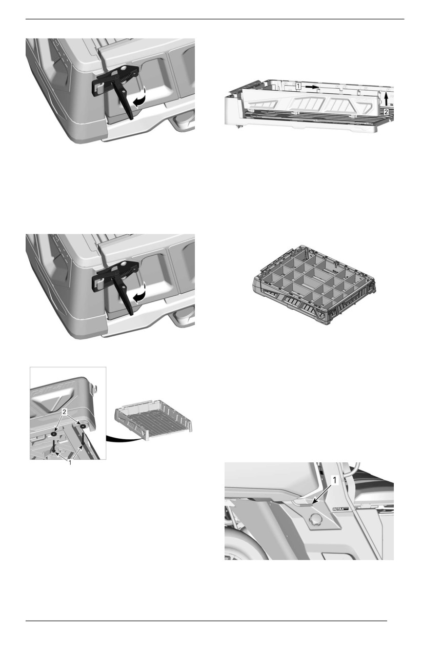
EQUIPMENT
LATCH HANDLE
1. Sliding backward
2. Lifting up
Cargo Box Siide Wallls
Cargo Box Separatiions
The side walls can be removed.
Cargo box can be easily separated in-
1. Open the latch handles and re-
to smaller storage compartments to
move the tailgate.
prevent cargo loads from mixing.
EXAMPLE
OF
CARGO
BOX
SEPARATIONS
2. Remove screws.
Cargo Box Tilt
Cargo Box Tiilt Release Handlles (If
equipped)
The latching mechanism of the cargo
box can be actuated from either side
of the vehicle through a release
handle.
1. Screw
2. Washer
3. Slide backward and lift up.
1. Cargo box release handle
93
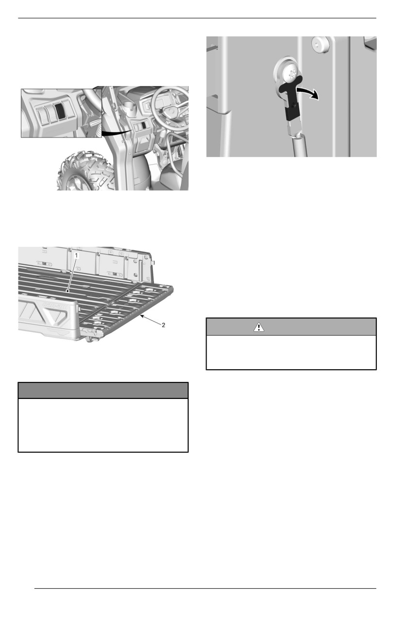
EQUIPMENT
Cargo Box Power-Tillt (If equipped)
The cargo box can be tilted with the
control switch located in the upper
control.
3. Lift the tailgate 45°.
4. Lift the RH side off it’s hinge.
5. Remove the tailgate by sliding it to
the right.
6. The installation is the reverse of
Tailgate
the removal procedure.
The cargo box can be closed with a
tailgate.
Trailer Hitch
The vehicle comes equipped with a
50.8 x 50.8 mm (2 x 2 in) standard re-
ceiver hitch.
For the proper usage of the hitch sup-
port, refer to Moving Loads and Doing
Work.
WARNING
To reduce the riisk of loss of con-
troll or loss of lload, always respect
1. Cargo box
the maximum hauliing capaciity.
2. Tailgate
12-Volt Power Outlets
NOTICE
Convenient for handheld spotlight or
Do not exceed 113 kg (250 llb) of
other portable equipment.
weight on the taiilgate duriing lload-
i
ing or unlloadiing. Allways cllose
tailgate before operatiing to re-
duce the risk of loss of load.
Removiing the Taillgate
1. Open tailgate.
2. Using a flat screwdriver, gently pry
the spring clip past the screw head
on each side.
94
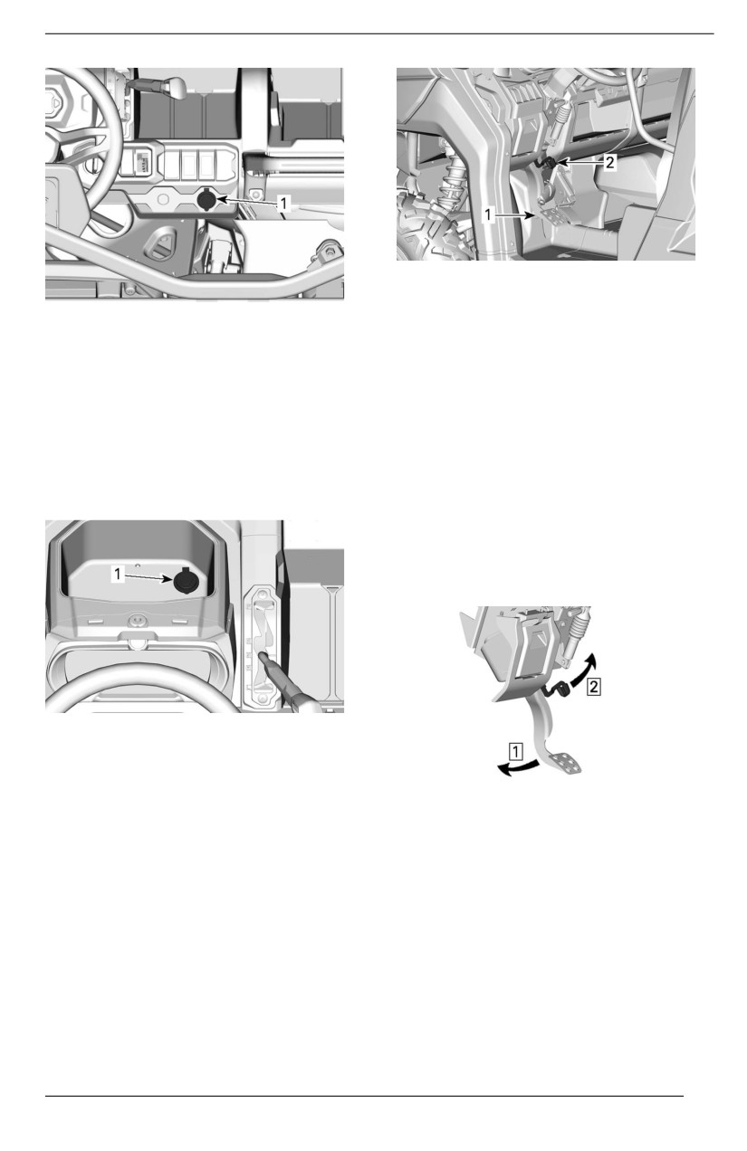
EQUIPMENT
TYPICAL
1. Brake pedal
ALL MODELS
2. Brake holding mechanism lever
1.
12 V power outlets
The brake holding mechanism func-
Remove protective cap to use. Always
tion is to maintain brakes to all wheels
reinstall it after use to protect against
while shift lever is set to Park.
weather.
To engage the brake holding mecha-
nism, proceed as follow:
USB Power Outlet
1. Immobilize vehicle,
Some models are equipped with a
2. Apply and hold the brakes,
USB port used for charging.
3. Put shift lever in Park,
4. While holding the brakes, lift lever
toward the steering wheel,
5. Remove foot from brake pedal, the
pedal should stay lowered.
1. USB charging port
Brake Holding Mechanism
The brake holding mechanism lever is
located on the LH side of the steering
Step 1. Apply and hold brake pedal
wheel, above the brake pedal.
Step 2. Lift lever
NOTE:
The brake holding mechanism lever
can be set to several positions.
95
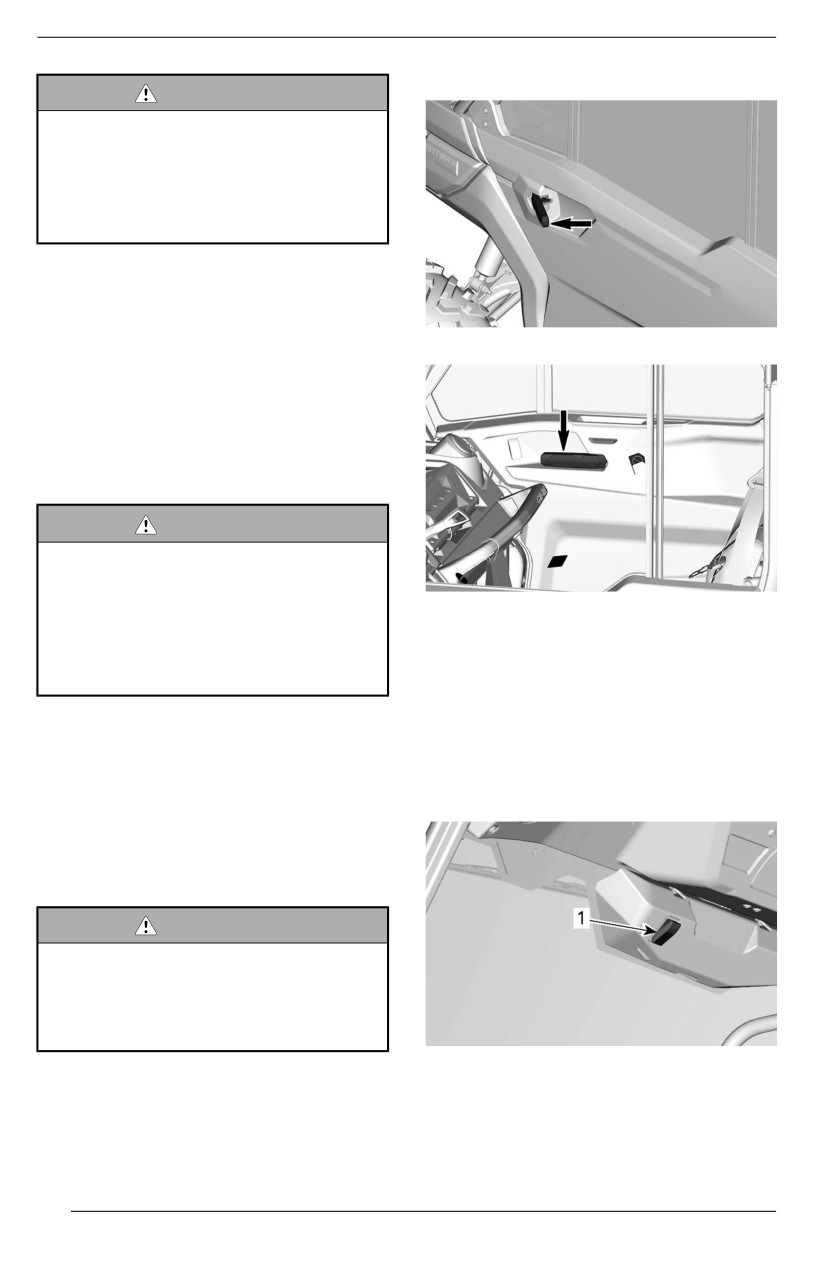
EQUIPMENT
Three-Window Doors
WARNING
When the brake holdiing mecha-
niism is appllied, make sure the ve-
hiiclle stays securelly iin place.
ALWAYS put the shift lever iin
PARK when using the brake holld-
i
ing mechanism.
To release the brake holding mecha-
nism, simply apply and hold the brake
pedal, put shift lever in gear then re-
lease brake pedal. When released it
OUTER DOOR HANDLE
should return to the rest position.
Safe usage of the brake holding
mechanism requires the shift lever to
be set to the Park position. It is not
recommended to use the brake hold-
ing mechanism on its own.
WARNING
Make sure brake holldiing mecha-
niism is released before operatiing
the vehiiclle. If the brake holdiing
INNER DOOR HANDLE
mechanism is lleft ON whille ridiing,
i
it may cause damage to the brake
Windshield with Wiper
system and lead to lloss of braking
capaciity and/or fire.
Some vehicles are equipped with a full
glass windshield and a wiper.
Full Doors With Electric
To activate wiper, press activation
Windows
switch. The switch is located on the
central panel at the top of the
Some vehicles come equipped with
windshield.
full doors and electric windows.
Doors can be removed from the ve-
hicle. See an authorized Can-Am Off--
road dealer for information.
WARNING
Always iinstalll safety nets and
shoulder bars whenever removing
full doors from vehiiclle. See an au-
thorized Can-Am Off-road dealer
for iinstalllatiion iinstructiions.
1. Wiper activation switch
To activate windshield washer, hold
activation switch up.
96
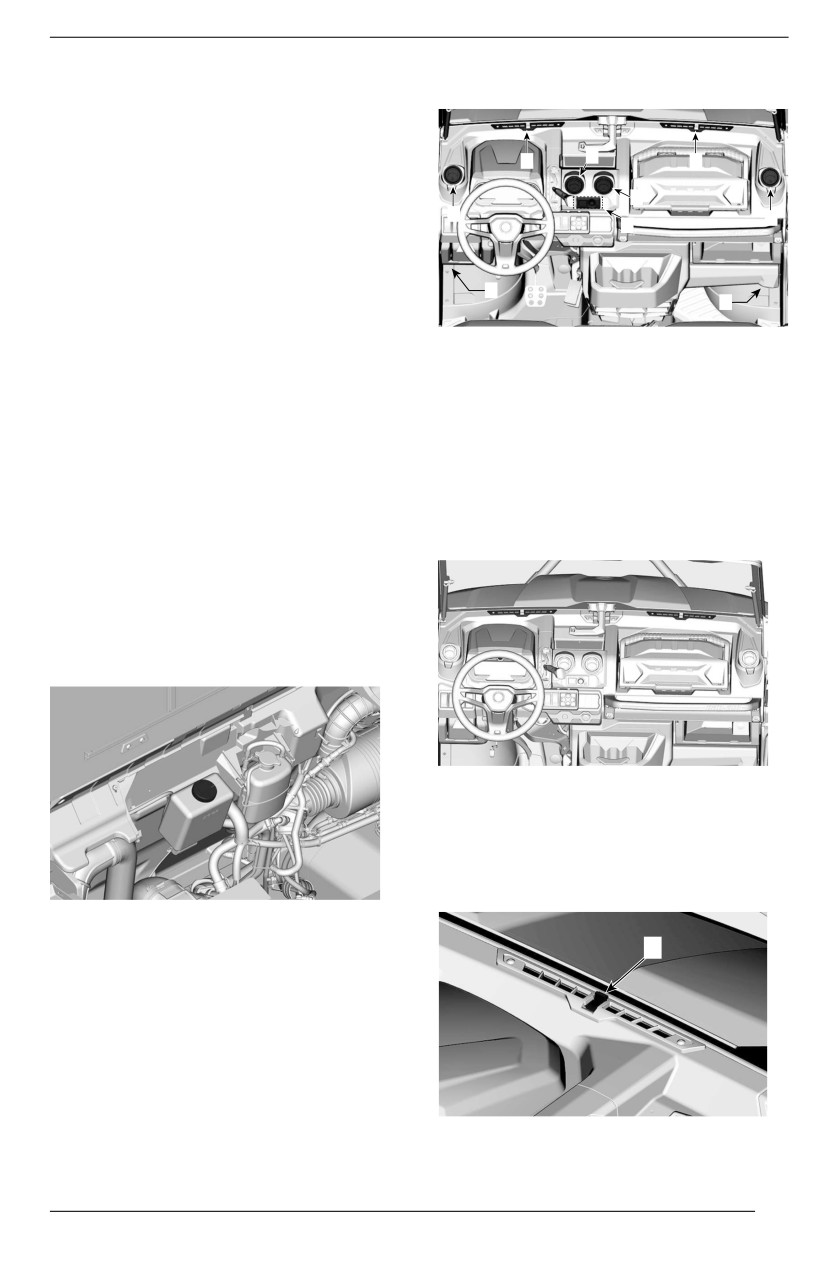
EQUIPMENT
Full glass windshield with wiper can
Climate Control System
be removed from vehicle. See an au-
thorized Can-Am Off-road dealer for
information.
1
2
1
Wiindshielld Posiition
2
Windshield can be set to 3 different
2
2
4
positions.
- Closed
- Partially opened (second position
3
on the handle)
3
- Fully opened (handle is released)
MODELS WITH A/C
NOTE:
1. Windshield air vents
When riding the vehicle with the wind-
2. Central air vents
shield in one of the open position, ad-
3. Footwell air vents
just your speed to the terrain. The
4. Climate control
glass windshield is not as strong when
not seated in its closed position.
Windshiield Aiir Vents
Located on the top of the dash, they
To close windshield, pull on handle
allow distribute the air flow on the
until it closes.
windshield.
Fillliing up Windshield Washer
Open cargo box.
Remove windshield washer bottle
cap.
The air flow may be adjusted using
the central knob.
- Push the knob toward the wind-
shield to close the vent.
- Pull it to open the vent.
Fill windshield washer bottle.
1
CLOSED POSITION SHOWN
1. Central knob
97
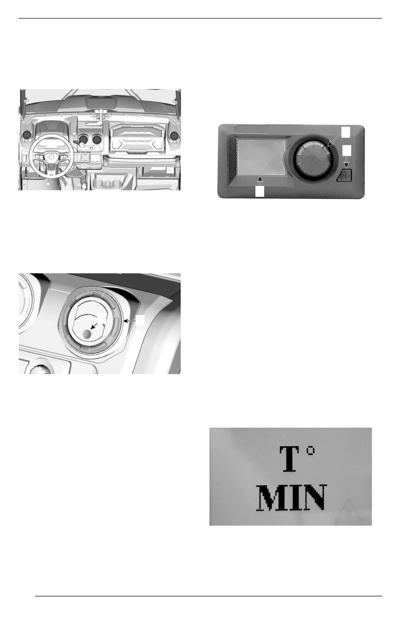
EQUIPMENT
Console Air Vents
This system is controlled by a multi-
function module. This module gives
Located on the center of the console,
access to the following functions:
they allow distribute the air flow inside
the cockpit.
- Temperature
- Temperature mode
- Fan speed
- Settings
2
1
3
Push on the molded dot to open the
vent.
1. Power switch
2. Selector knob
Push on vent tabs to close.
3. Display
Rotate the external ring of the vent to
For an optimal efficiency of the sys-
orient the air flow in the cockpit.
tem, the supply control of the outside
air is determined automatically by the
climate control module. No operator
action is required.
1
Temperature
2
To adjust the temperature, turn the se-
lector knob to select the desired
temperature.
The temperature can be set between
13 °C and 28 °C (56 °F and 82 °F) in 1
1. Molded dot
degree increments.
2. External ring
In position T
° MIN, the system
Footwelll Air Vents
switches to continuous cooling.
Located underneath the dash, each
side of the vehicle, they allow distrib-
ute the air flow at the bottom of the
cockpit.
Push on the molded dot to open the
vent.
Push on vent tabs to close.
Cliimate Controll - Wiith A/C
This vehicle is equipped with an heat-
In T ° MAX, the system switches to
ing/air conditioning system.
continuous heating.
98
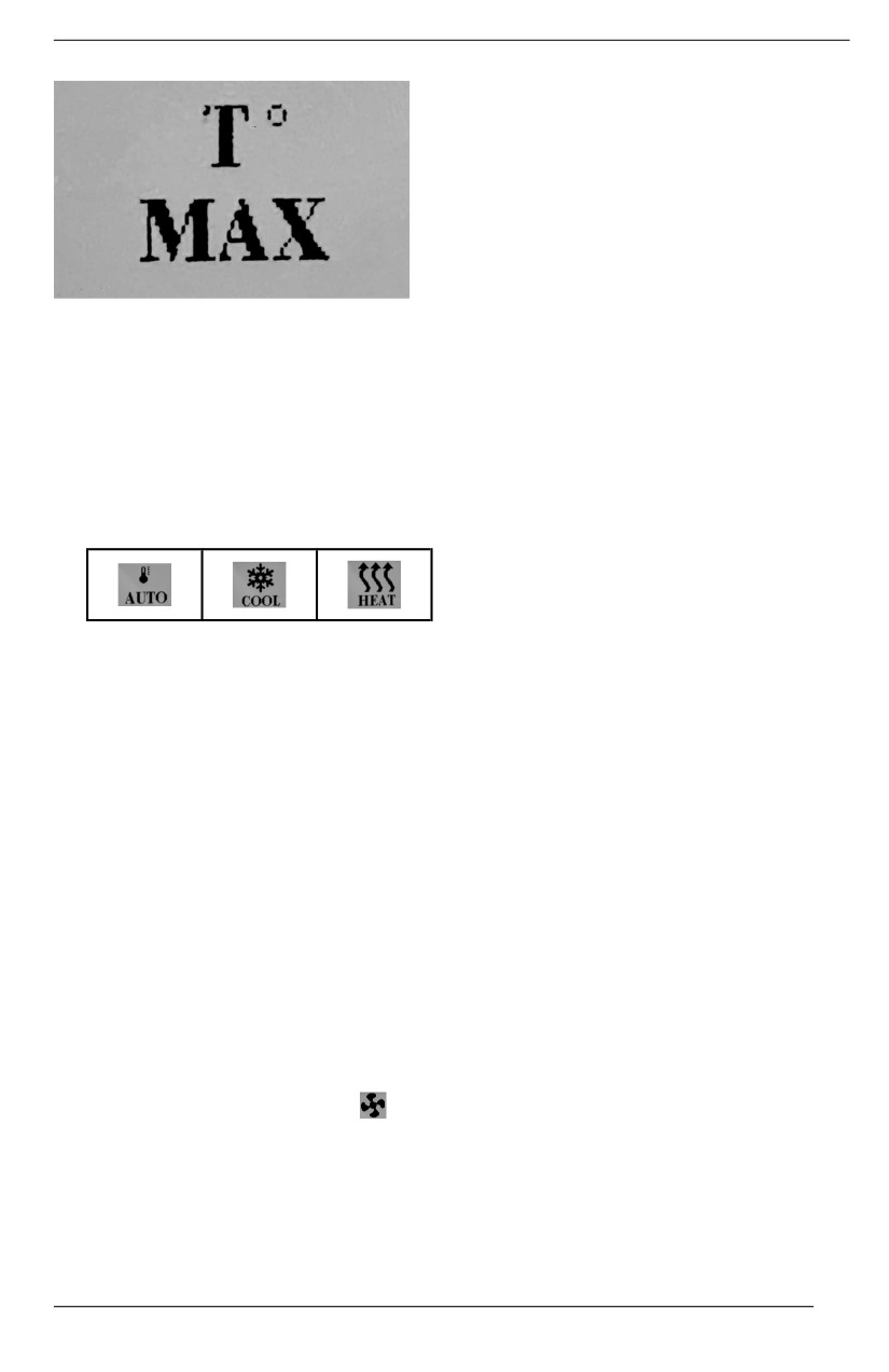
EQUIPMENT
- MED
- HIGH
NOTE:
After
5 seconds, the module saves
your selection and returns automati-
cally to the temperature display.
Setting
The following settings can be modified
by the operator.
NOTE:
- Contrast (0% to 100%)
In either T ° MIN or T ° MAX position,
- Brightness (0% to 100%)
the system can not regulate a stable
- Unit (°C or °F)
temperature.
To modify a setting, press the selector
Temperature Mode
knob 2 time to reach the Fan Speed
1. To select the temperature mode,
page.
press the selector knob until one of
the following icon appear.
NOTE:
Each next action must be performed
within 10 seconds, otherwise the mod-
ule will come back to the temperature
display.
2. Turn the selector knob to change
the mode.
Press and hold the power button while
turning the selector knob clockwise for
NOTE:
at least 3 clicks.
After
5 seconds, the module saves
To change the CONTRAST: turn the
your selection and returns automati-
selector knob until the desired level is
cally to the temperature display.
reached.
In AUTO mode, the system automati-
To change the BRIGHTNESS: press
cally adjusts to heat or cool the cockpit
the selector knob 1 time, then turn the
to obtain the selected temperature as
knob until the desired level is reached.
quickly as possible by adjusting the
fan speed automatically.
To select °C or °F: press the selector
knob 2 times, and turn the knob to
If an other fan speed is selected while
change the unit.
in AUTO mode, the system will fall in
cool or heat mode depending the am-
bient conditions.
Fan Speed
To adjust the fan speed, press the se-
lector knob until the fan icon
ap-
pears then turn the knob to select the
desired speed.
3 settings are available for fan speed:
- LOW
99
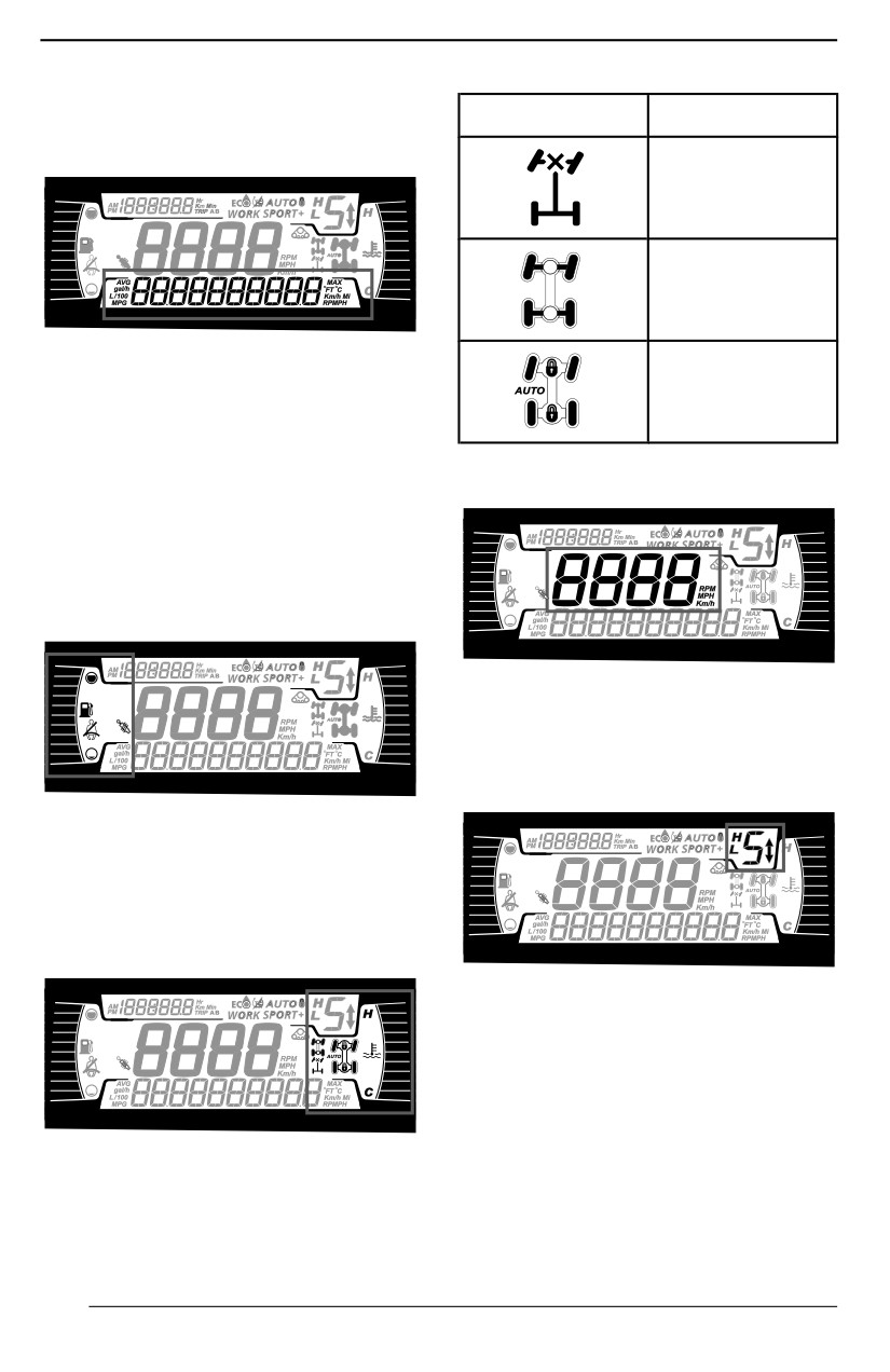
4.5” DIGITAL DISPLAY
Multifunction Display
Icon
Descriiptiion
Lower Display
2x4 icon
4X4 icon
May display the following:
Front differential
- RPM
lock
- Speed statistics
- Engine Temperature
- Battery Voltage
Central Display
- Settings
- Messages
Use LOWER button to change the dis-
played information.
Left Lateral Display
Display the vehicle speed in km/h or
MPH or RPM.
Transmission
Position
Display
The left lateral display includes:
- Fuel level indicator
- Seat belt icon
- Smart-Shox suspension icon
Right Lateral Display
This display shows gear position of
gearbox:
- P (Park)
- R (Reverse)
- N (Neutral)
- H (High Range)
- L (Low Range)
The right lateral display includes:
- Gear 1 to 7
-
- (Invalid Range)
- Engine Temperature
–
2WD/4WD/Diff lock
Engine Mode Display
100
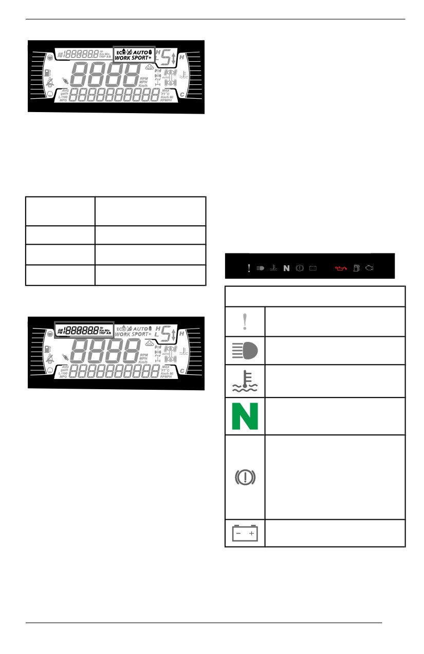
4.5” DIGITAL DISPLAY
Warning Lamps and
Indicators
The following indicator lamps will alert
you to a vehicle condition that may be-
come serious. Some lamps will illumi-
nate when starting the vehicle to
make sure they work. If any lamps re-
main on after starting the vehicle, refer
The MODE display indicates the se-
to the respective system warning lamp
lected mode of operation:
for further information.
- AUTO mode
- NORMAL
NOTE:
- SPORT
Some warning indicators appear in
- SPORT+
the display of the multifunction gauge
and function the same as an indicator
Message at
Driive Mode
lamp but do not display when starting
Actiivatiion
the vehicle.
Normal
NORMAL MODE
Tellltale Lights - Lower Bar
Sport
SPORT MODE
Sport+
SPORT+ MODE
Warniing and Tellltalle Liights
Trip Display
ORANGE - Vehicle
Malfunction
BLUE - High Beam
RED - The engine
temperature is too high.
This display shows trip information:
GREEN - Neutral
- Cumulative distance odometer
- Trip A
- Trip B
RED - (Blinking)
- Vehicle hour meter
Accelerator pedal and the
- Clock
brake are activated
simultaneously for a certain
time
(a torque limitation is
Use UPPER button to change the dis-
active)
played information.
Hold UPPER button to reset Trip A/B
RED - Low battery.
meters.
101
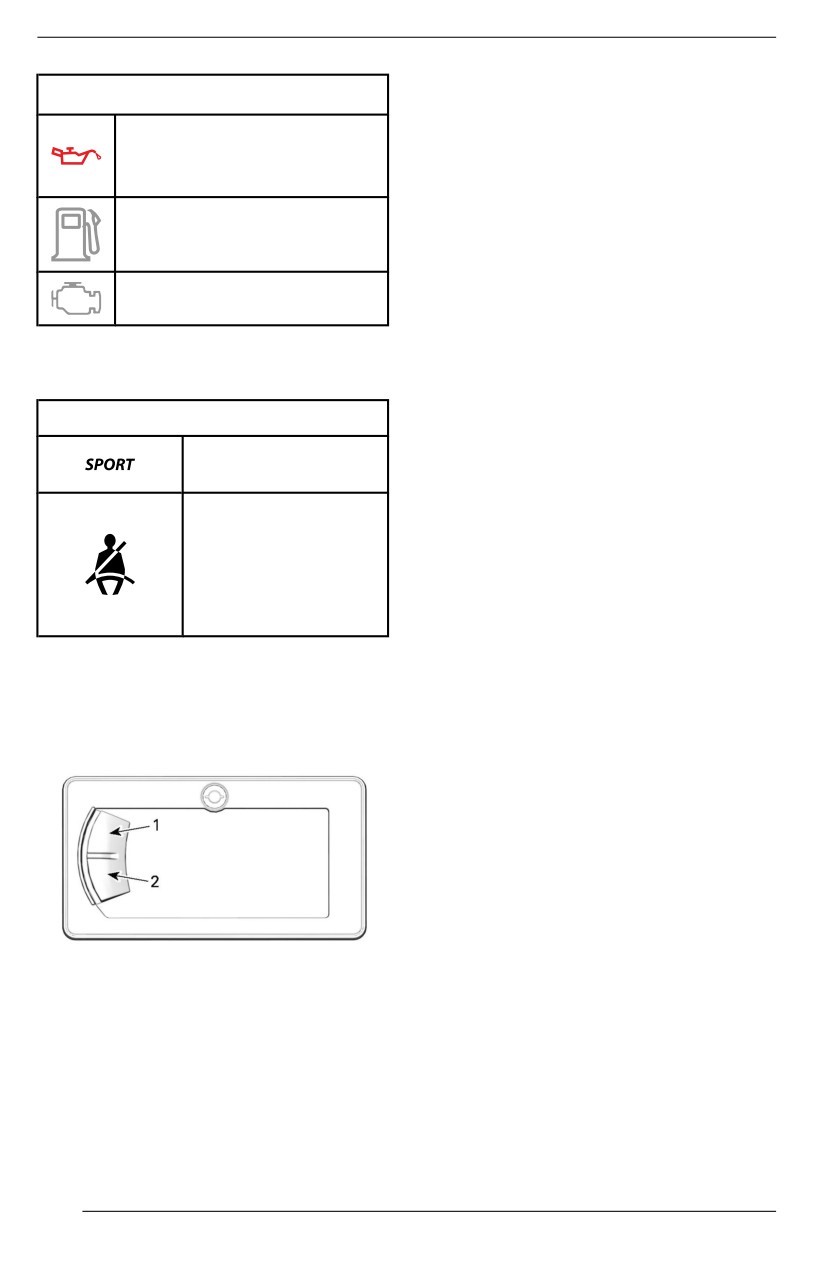
4.5” DIGITAL DISPLAY
Maintenance Reset
Warniing and Tellltalle Liights
NOTE:
RED - Low oil pressure
Only when the maintenance icon is
(Normally ON at engine
displayed.
OFF)
Using LOWER button, select RES
MAINT and hold to reset
ORANGE - Low fuel level
maintenance.
Faullt Codes
ORANGE - Check engine
Available only when at least one code
is activated.
Icons and Indicators - Multiifunctiion
Using LOWER button, select CODES
Display
and hold to see actives fault codes.
Icons and Indicators
Fault codes will be scrolled on the
Denotes SPORT
Lower Display.
mode is selected.
Reset Stats
When lit, seat belt
Using LOWER button, select RESET
not buckled with
STAT and hold to reset.
vehicle
immobilized.
Unit Sellectiion
Flashing when
vehicle is moving.
This multifunction gauge is factory
preset in Imperial units but it is possi-
ble to change it to Metric units.
Settings
Using LOWER button, select UNITS
The buttons to navigate through me-
and hold button to change units.
nus are located on the left side of the
LCD display.
Settiing Clock
All of the following action must be per-
formed using the LOWER button.
1. Select CLOCK and hold to adjust
clock.
2. Press the button to select clock
display.
1
3. Push and hold the button for
second.
1. Upper button
4. Press the button to select 12:00
2. Lower button
AM PM or 24:00 time base.
5. Push and hold the button to ac-
Setup
knowledge selection.
Using LOWER button, select SET-
6. Press the button to change hours
TINGS and hold to enter setting
(hours flash).
menu.
7. Push and hold the button to ac-
knowledge hour selection.
8. Press the button to switch to mi-
nutes (minutes flash).
102
4.5” DIGITAL DISPLAY
9. Push and hold the button to ac-
knowledge minutes selection.
Settiing Language
The gauge display language can be
changed.
Refer to an authorized Can-Am Off--
road dealer for language availability
and to setup the gauge to your
preference.
Settiing Brightness
The brightness of the LCD display can
be adjusted.
Using LOWER button, select
BRIGHTNESS and hold button to
change brightness.
Using LOWER button, adjust bright-
ness then push and hold the button to
acknowledge selection.
103
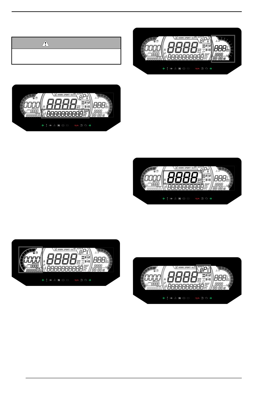
7.6" DIGITAL DISPLAY
Multifunction Display
WARNING
Do not adjust the display whiile
riding, you coulld lose controll.
Lower Display
The right lateral display includes:
- Engine Temperature
- Clock
- Speed indicator
The speed indicator in this display is
activated when the central display
shows information other than the
speed. Otherwise it is blank.
May display the following:
- RPM
Central Display
- Speed statistics
- Engine Temperature
- Battery Voltage
- Settings
- Messages
- Active DPS mode
The SPEED STAT display shows the
maximum and the average speed.
Hold MENU or OK button for 1 second
May display the following:
to reset.
- RPM
Left Lateral Display
- Vehicle speed
Transmission
Position
Display
The left lateral display includes:
- Fuel level indicator
- Tripmeter (A - B)
This display shows gears position of
- Odometer
gearbox:
- Vehicle Hour meter
- DPS indicator
- AUTO (Automatic)
- P (Park)
Right Lateral Display
- R (Reverse)
- N (Neutral)
- H (High range)
- L(Lowrange)
104
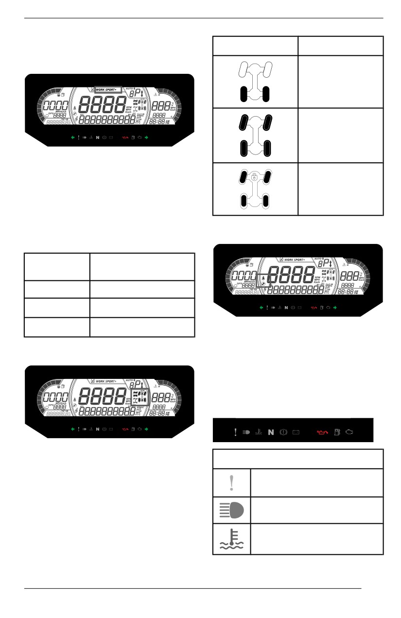
7.6" DIGITAL DISPLAY
-
- (Invalid gear)
Icon
Description
Engine Mode Display
2x4 icon
4X4 icon
The engine mode display indicates
the selected mode of operation:
- NORMAL
Front differential
- SPORT
lock
- SPORT+
A message of the selected mode will
Middle Left Display
be displayed on the lower display at
activation and deactivation as follow:
Message at
Driive Mode
Actiivatiion
Normal
NORMAL MODE
Sport
SPORT MODE
Sport+
SPORT+ MODE
The middle left lateral
display
includes:
Middle Right Display
- Seat belt reminder
- Maintenance reminder
Indicator Lamps
Warniing and Tellltale Lights
The middle right display indicates the
WARNING and Tellltale Lights
selected mode of operation:
-
2X4
ORANGE - Vehicle
–
4X4
Malfunction
–
Front differential lock (Smart-Lok)
BLUE - High Beam
RED - The engine
temperature is too high.
105
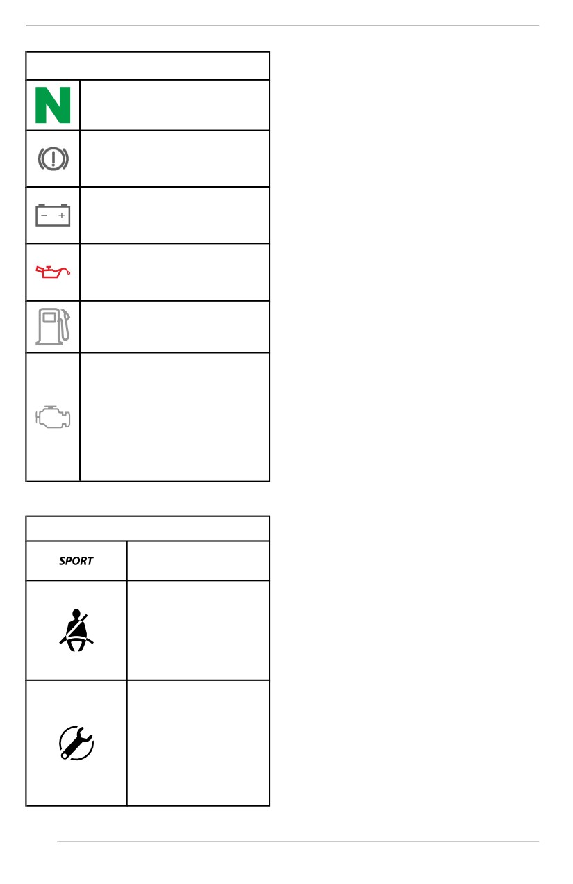
7.6" DIGITAL DISPLAY
Settings
WARNING and Tellltale Lights
Setup
GREEN - Neutral
Using the MENU button on the key-
pad, select SETTINGS and hold to
enter setting menu.
RED - Brake lock lever is
engaged or malfunction of
OK button can be pressed instead of
the brake system
holding MENU button.
RED - The battery voltage
Maintenance Reset
too low or problem with the
electrical system
NOTE:
Only when the maintenance icon is
RED - Low oil pressure
displayed.
Normally ON when engine
is OFF
Using MENU button, select RES
MAINT and hold to reset
maintenance.
ORANGE - Low fuel level
Faullt Codes
ORANGE
Available only when at least one code
Turn on: Malfunction of the
is activated.
vehicle emissions control
system
Using MENU button, select CODES
Bllink: Engine problems,
and hold to see active fault codes.
the limp home mode is
Fault codes will be scrolled on the
activated. Have the vehicle
Lower Display.
serviced immediately.
Reset Stats
Icons and Indicators
Using MENU button, select RESET
STAT and hold to reset.
Icons and Indicators
Denotes SPORT
Unit Sellectiion
mode is selected.
This multifunction gauge is factory
preset in Imperial units but it is possi-
When lit, seat belt
ble to change it to Metric units.
not buckled with
vehicle
Using MENU button, select UNITS
immobilized.
and hold button to change units.
Flashing when
vehicle is moving.
Speed/RPM
When lit, indicates
The speed and RPM display can be
that a maintenance
swapped.
is required. See
Using MENU button, select SPEED/
your authorized
RPM and hold button to invert speed
Can-Am dealer or
and RPM display.
person of your own
choosing for the
maintenance.
106
7.6" DIGITAL DISPLAY
Settiing Cllock
All of the following action must be per-
formed using the MENU button.
1. Select CLOCK and hold to change
time.
2. Press the button to select clock
display.
3. Push and hold the button for
1
second.
4. Press the button to select 12:00
AM PM or 24:00 time base.
5. Push and hold the button or OK
button to acknowledge selection.
6. Press the button to change hours
(hours flash).
7. Push and hold the button or OK
button to acknowledge hour
selection
8. Push the button to switch to mi-
nutes (minutes flash).
9. Push and hold the button to ac-
knowledge minutes selection.
Settiing Brightness
The brightness of the LCD display can
be adjusted.
Using MENU button, select BRIGHT-
NESS and hold MENU button to se-
lect the brightness setting.
Using MENU button, adjust brightness
then push and hold MENU button to
acknowledge selection.
Settiing Language
The gauge display language can be
changed.
Refer to an authorized Can-Am Off--
road dealer for language availability
and to setup the gauge to your
preference.
DPS Modes
The lower display can show which
DPS mode is active. Refer to Tune
Your ride.
107
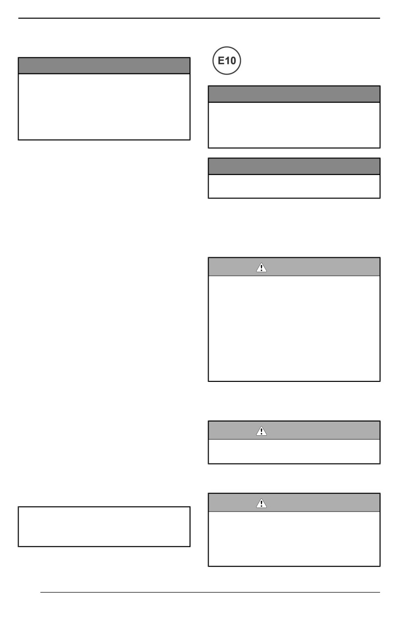
FUEL
Fuel Requirements
NOTICE
Always use fresh gasoliine. Gaso-
l
line willl oxidiize; the result is loss
NOTICE
of octane, volatille compounds,
and the production of gum and
Never experiment with other
varnish deposits whiich can dam-
fuells. Engiine or fuell system dam-
age the fuel system.
ages may occur wiith the use of an
inadequate fuel.
Alcohol fuel blending varies by coun-
try and region. Your vehicle has been
NOTICE
designed to operate using the recom-
Do NOT use fuel from fuell pumps
mended fuels, however, be aware of
labeled E85.
the following:
-
Use of fuel containing alcohol
Use of fuel labeled E15 is prohibited
above the percentage specified by
by U.S. EPA Regulations.
government regulations is not rec-
ommended and can result in the
Vehicle Fueling Procedure
following problems in the fuel sys-
tem components:
WARNING
- Starting and operating
– Fuell is flammable and explo-
difficulties.
sive under certaiin conditions.
- Deterioration of rubber or plas-
tic parts.
– Never use an open fllame to
- Corrosion of metal parts.
check fuell level.
- Damage to internal engine
– Never smoke or alllow fllame or
parts.
spark iin viicinity.
– Always work iin a welll-venti-
-
Inspect frequently for the presence
llated area.
of fuel leaks or other fuel system
– Vehiiclle must be on a llevell sur-
abnormalities if you suspect the
face to perform fueliing.
presence of alcohol in gasoline ex-
ceeds the current government
regulations.
1. Place vehicle on a level surface.
-
Alcohol blended fuels attract and
2. Stop engine.
hold moisture which may lead to
fuel phase separation and can re-
WARNING
sult in engine performance prob-
Allways stop engine before
lems or engine damage.
refueliing.
Recommended Fuell
3. Have occupants get out of vehicle.
The gasoline must have the following
minimum octane requirements:
WARNING
Regular unleaded gasoline with an
Do not alllow anyone to remaiin iin
AKI (R+M)/2 octane rating of 87, or
the vehicle whiile fueliing. If there
an RON octane rating of 91
is a fire or expllosiion during fuell-
ing, a vehiclle occupant could be
unablle to quicklly leave the area.
Use unleaded gasoline containing
MAXIMUM 10% ethanol.
108
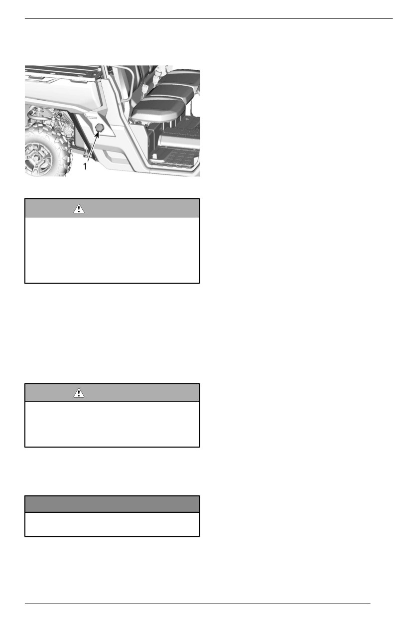
FUEL
4. Slowly unscrew the fuel reservoir
cap counterclockwise to remove it.
1. Fuel reservoir cap
WARNING
If a diifferentiial pressure conditiion
i
is noticed (whistliing sound heard
when lloosening fuel reservoiir
cap) have vehicle iinspected and/
or repaiired before further
operation.
5. Insert the spout into the filler neck.
6. Pour fuel slowly so that air can es-
cape from the tank and prevent
fuel flow back. Be careful not to
spill fuel.
7. Stop filling when the fuel reaches
the bottom of filler neck. Do not
overfiilll.
WARNING
Never top up the fuel tank before
placing the vehicle iin a warm
area. As temperature increases,
fuell expands and may overflow.
8. Fully tighten fuel reservoir cap
clockwise until you hear a clicking
noise.
NOTICE
Allways wiipe off any fuell spiilllage
from the vehiicle.
109
BREAK-IN PERIOD
Operation During Break-In
A break-in period of
10
operating
hours or 300 km (200 mi) is required
for the vehicle.
Engiine
During the break-in period:
- Avoid full throttle operation.
- Avoid pressing accelerator pedal
more than 3/4 of the stroke.
- Avoid sustained accelerations.
- Avoid prolonged cruising speeds.
- Avoid engine overheating.
However, brief accelerations and
speed variations contribute to a good
break-in.
Brakes
WARNING
New brakes wiilll not operate at
their maximum efficiiency untill
their break-iin is completed. Brak-
i
ing performance may be reduced,
so use extra cautiion.
Applly moderate braking force for
the 40 to 50 first braking events.
Bellt
A new belt requires a break in period
of 50 km (30 mi).
During the break-in period:
- Avoid strong acceleration and
deceleration.
- Avoid pulling a load.
- Avoid high speed cruising.
110
BASIC PROCEDURES
Starting the Engine
Pay attention to the following:
Press the brake pedal.
Low range
Insert key in ignition switch and turn to
Low range should be used whenever:
the ON position.
-
Pulling
–
Pushing
NOTE:
–
Hauling a load
If shift lever is not set to PARK (P) or
–
4x4 applications
(N) NEUTRAL, the brake pedal must
–
Mud holes
be pressed to allow engine starting.
–
Water holes
–
Crossing obstacles
Turn the key to the start position and
–
Climbing onto trailer
hold until the engine starts.
–
Hill climbing
NOTE:
It is also recommended to use low
Do not press the accelerator pedal. If
range if driving for prolonged periods
the accelerator pedal is pressed at
at speeds under 24 km/h
least 50%, the engine will not start.
(15 MPH).
Release the engine start position im-
Please refer to Break-in Period for
mediately when the engine has
drive belt break-in information.
started.
High range
NOTICE
High is the default riding range.
If engine does not start after a few
seconds, do not hold the start po-
Ellectronic Drive Belt Protectiion (iif
sition more than 10 seconds. Re-
avaiilable and activated on your
fer to Troubleshooting.
model)
Some vehicles have the electronic
drive
belt
protection
function
Operating the Shift Lever
activated.
Apply brakes and select the desired
shift lever position.
Refer to your authorized Can-Am Off--
road dealer for availability and possi-
Release brakes.
ble activation.
NOTICE
This function is activated when riding
at too slow speed for the hiigh range,
When changiing gear sellection, al-
such as in the following situations:
ways complletelly stop the vehiiclle
and apply the brakes priior to shift-
-
Pulling
i
ing. Damage to the gearbox may
–
Pushing
occur.
–
Hauling a load
-
4x4 applications
–
Mud holes
Choosing the Correct Range
–
Water holes
(Low or High)
–
Crossing obstacles
It is important to limit situations known
–
Climbing onto trailer
to make the drive belt slip excessively.
–
Hill climbing
The main reason the drive belt will slip
In the above mentioned situations the
is if the gearbox is in high range when
electronic drive belt protection will
it should be in low range.
help protect the CVT drive belt from
111
BASIC PROCEDURES
being damaged by activating the en-
Tips for Maximizing Drive
gine torque limiter. The gauge will also
Belt Durability
scroll a LOW GEAR message, sug-
gesting the operator to immobilize the
Riding style and conditions have a di-
vehicle and set to LOW GEAR.
rect impact on drive belt durability.
Your vehicle features a CVT system
Whenever the ellectroniic drive bellt
design that is optimized to offer the
protection is actiivated, you MUST
best performance. The CVT and drive
shift in LOW range. Refer to Operat-
belt have successfully endured thou-
ing the Shift Lever.
sands of miles of durability tests. How-
ever, to maximize drive belt durability
Stopping the Engine and
and to prevent premature failures, it is
important that the operator under-
Parking the Vehicle
stands the limits of a belt driven CVT
system and adapts their riding style
WARNING
and speed accordingly.
Avoiid parking on steep sllope as
the vehiiclle may rolll away.
If riding in any of the conditions listed
below, BRP highly recommends not to
constantly hold the throttle wide open
WARNING
(WOT) for more than five (5) minutes.
Always put the vehiiclle in PARK
- High ambient temperatures (above
when stopped or parked to pre-
30 °C (86 °F)
vent rollliing.
- Heavy loads: Passengers / Heavy
cargo
- Heavy drag: Soft sand / Hill climb-
WARNING
ing / Mud / Using a track kit.
Avoiid parking iin pllaces where hot
After a few minutes at WOT, partially
parts can start a fiire.
release the accelerator and allow the
CVT to cool down.
When stopped or parked always bring
For more tips for maximizing the drive
shift lever to park position. This is es-
belt durability, refer to Choosing the
pecially important when parking on a
Correct Range (Low or High).
slope. On very steep inclines or if the
vehicle is carrying a cargo, the wheels
should be blocked using rocks or
bricks.
Select the flattest terrain available for
parking.
Release accelerator pedal and use
brakes to completely stop the vehicle.
Set shift lever in PARK position.
Turn key in ignition switch to OFF
position.
Remove key from ignition switch.
112
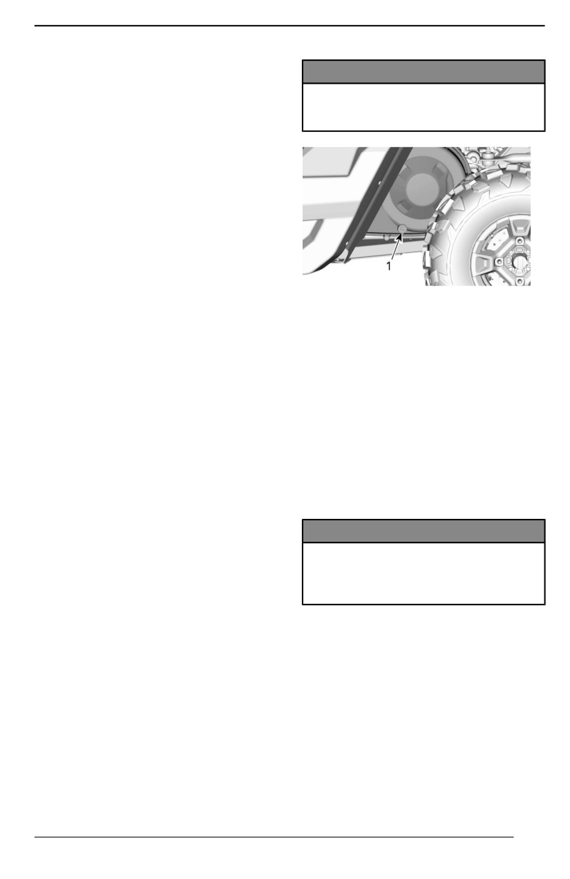
SPECIAL PROCEDURES
NOTE:
NOTICE
Component failures resulting from
these events are not covered by
Stop the engine and draiin the
warranty.
water to avoiid damage to the
CVT.
Fuel Flooded Engine
If the engine does not start and it is
fuel-flooded, the drowned mode can
be activated to prevent fuel injection
and to cut ignition while cranking. Pro-
ceed as follows:
1. Move shift lever in park position.
2. Turn the ignition key in ON
position.
3. Press completely and HOLD ac-
TYPICAL
- LEFT SIDE OF VEHICLE
celerator pedal.
UNDER CARGO BOX
4. Turn the ignition key to the START
1. CVT drain
position and hold in this position
for 10 seconds.
See an authorized Can-Am dealer , a
5. Release the ignition key.
repair shop or person of your choos-
6. Release
accelerator
pedal
ing to have the CVT inspected and
completely.
cleaned.
7. Turn the ignition key to START po-
sition again to allow starting.
What to do if Battery is
If it does not work:
Drained Out
1. Remove the spark plugs. Refer to
The vehicle can be jump started by
Spark Plugs in Maintenance Pro-
using the RED (+) cable to the battery
cedures section.
positive pole and the BLACK (-) cable
2. Crank engine several times.
to the vehicle chassis.
3. Install new spark plugs if possible
or clean and dry spark plugs.
NOTICE
Do not connect any electriicall
If engine does not start, see an au-
source to the steeriing column or
thorized Can-Am Off-road dealer, a
components which are in contact
repair shop, or a person of your own
wiith DPS.
choosing for maintenance, repair, or
replacement.
What to Do if Vehicle Rolled
Please refer to the US EPA Emis-
Over
sion-Related Warranty contained
herein for information about warranty
Abrupt maneuvers, sharp turns, side
claims.
hilling or accident may cause vehicle
to rollover.
What to do if Water is
Should the vehicle be rolled over, it
Suspected to be in the CVT
will be necessary to have it trans-
If water is present in the CVT, the en-
ported to an authorized Can-Am Off--
gine will accelerate but the vehicle will
road dealer for inspection as soon as
remain still.
possible. NEVER START THE
ENGINE!
113
SPECIAL PROCEDURES
Points to be verified, including but not
limited to:
- All fluid levels
- Seat belts, including retractors,
buckles and semi-cinching tabs
- Cage and its attachment points
- Steering system
- Suspension and its attachment
points.
What to do if Vehicle is
Submerged
Should the vehicle become immersed,
it will be necessary to have it trans-
ported to an authorized Can-Am Off--
road dealer as soon as possible.
NOTICE
Never start the engiine as immer-
siion of the vehicle can cause seri-
ous damage to the engiine if the
correct restart procedure is not
followed.
114
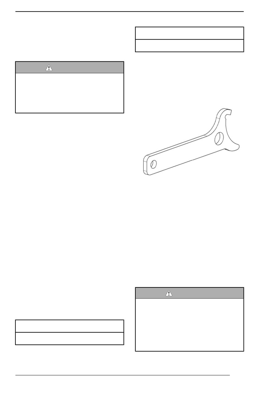
TUNE YOUR RIDE
Suspension Adjustment
Spriing Preload
Guidelines
Cam position 1 (soft)
Your vehicle handling and comfort de-
pend upon suspension adjustments.
Suspension Adjustments
WARNING
Suspension adjustment coulld af-
Spriing Preload Adjustment
fect vehiiclle handling. Always take
Following are guidelines to fine-tune
time to familiarize yourself with
suspension. Use suspension adjust-
the vehicle''s behavior after any
ment tool provided in the tool kit.
suspensiion adjjustment has been
made.
Choice of suspension adjustments
vary with vehicle load, personal pref-
erence, riding speed and terrain
condition.
The best way to set up the suspen-
sion, is to start from factory settings,
then customize each adjustment one
at a time.
Front and rear adjustments are inter-
The spring preload affects the ground
related. It may be necessary to read-
clearance of the vehicle.
just the rear shock absorbers after
adjusting front shock absorbers for
Shorten the spring for a firmer ride
instance.
and rough riding condition or when
pulling a trailer.
Test run the vehicle under the same
conditions; trail, speed, load, etc.
Lengthen the spring for a softer ride
Change one adjustment and retest.
and smooth riding condition.
Proceed methodically until you are
satisfied.
NOTE:
Factory settings are suitable for al-
Suspension Factory Settings
most all conditions. Take into consid-
eration that an increase in ground
Factory settings are suitable for al-
clearance can affect the handling of
most all conditions.
the vehicle.
Take into consideration that an in-
crease in ground clearance can affect
WARNING
the handling of the vehicle.
The lleft and right shock adjust-
ment on front or rear suspension
Front Suspension
must always be set to the same
position.
Spring Prelload
Never adjust one shock only.
Uneven adjustment can cause
Cam position 1 (soft)
poor handlling and lloss of stability,
which coulld lead to an accident.
Rear Suspension
115
TUNE YOUR RIDE
Lift the vehicle to adjust spring
preload.
Adjust by turning adjusting cam.
1. Turn adjusting cam
2. Soft adjustment
3. Firm adjustment
DPS Function
The Dynamic Power Steering (DPS)
provides a computer controlled, varia-
ble power assist, achieved by an elec-
tric motor to optimize the amount of
steering input required by the rider.
116

TRANSPORTING THE VEHICLE
When contacting a towing or transporting service, be sure to ask if they have a
flatbed trailer, loading ramp or power ramp to safely lift the vehicle and tie-down
straps. Ensure the vehicle is properly transported as specified in this section.
NOTICE
Do not tow this vehiiclle — towing can seriouslly damage the vehicle''s drive
system.
NOTICE
Avoid using chaiins to tiie the vehiicle — they may damage the surface fiin-
i
ish or plastiic components.
WARNING
To avoiid severe injury or death or important components damages.
– Never use the winch cable/rope to retaiin a vehicle during trailleriing.
– Never riide wiith the wiinch cablle/rope attached to a load or another
vehicle.
– Onlly use the winch to help a stuck vehicle (snow, mud, etc.).
– Always refer to the wiinch manufacturer''s instruction before pullliing
l
loads.
WARNING
Make sure alll accessories, cargo and lloose objjects inside the vehicle are
properlly secured, or remove iit to prevent from failling on the road and cre-
ating a hazard for folllowiing vehicles.
WARNING
Allways transport the vehicle faciing forward to avoiid damagiing the wiind-
shield or other components. Parts may detach during transport.
WARNING
Before attemptiing to mount vehicle onto a platform or a trailer, make sure
to respect the folllowiing safety precautions.
Safety Precautiions
The carrying item (platform or trailer or flat bed)
must be of appropriate dimensions and
Carrying equipment
capacity to safely support and transport the
vehicle.
Do not exceed vehicle hauling capacity and
Hauling vehicle
specifications. Ensure the trailer or platform is
properly secured to the hauling vehicle hitch.
117
TRANSPORTING THE VEHICLE
Safety Precautions
Ensure you have a good visibility during the
Visibility
entire maneuver.
The hauling vehicle and trailer must be on a
Terrain
leveled surface. Use wheel chocks on trailer
and hauling vehicle to avoid any movement.
Use ramps with proper rating and secure ramps
Ramps
to the trailer or platform. Avoid steep ramps.
Always make sure bystanders are not close to
Bystanders
the vehicle or the trailering equipment while
climbing up.
Make sure all accessories, cargo and loose
objects inside the vehicle are properly secured,
Accessories and cargo
or remove it to prevent from failing on the road
and creating a hazard for following vehicles.
Using Vehicle Power to Climb Onto Trailering Equipment
When vehicle can cllimb on its own power, proceed as folllows;
1. Wear protective gear.
2. Fasten seat belt.
3. Use low gear only (if equipped).
4. Activate the 6WD position.
5. When driving remain seated at all times.
6. Ensure proper alignment on rails or platform.
7. Start from a sufficient distance from the trailer to align the vehicle in a straight
line with the ramps. Never attempt to turn while getting closer to the ramp.
Rear wheels might not be aligned once you get to the ramp and vehicle may
fall off.
8. Slowly climb the front wheels onto the ramp to verify alignment.
9. Back off the vehicle, verify ramps are still secure, then proceed at proper
speed.
10. Carefully drive vehicle onto platform or trailer. Use sufficient speed to climb
without spinning or abruptly accelerating. Avoid acceleration while on ramps
to prevent ramps movement.
11. If trailer is inclined towards front, simply let vehicle roll in without acceleration.
12. Once vehicle is climbed, put shift lever to Park. Apply brake locking mecha-
nism (if equipped).
When vehiicle cannot move on its own power, or iin case overshootiing is
a riisk or iif any dangerous conditiion prevents for embarkiing on its own
power, proceed using a wiinch;
Using a Winch to Pull Vehicle Onto Trailering Equipment
When vehicle cannot cllimb on iits own power, proceed as folllows;
118

TRANSPORTING THE VEHICLE
WARNING
Have the help of an assistant. One person shoulld be iin vehiclle to have
access to vehiiclle steering, brakes and winch switch, whille the other per-
son controlls the enviironment and safety of the maneuver.
WARNING
Ensure the winch hook can be safely attached to a proper anchoring
point. Use proper rigging.
NOTE:
If vehicle can be started safely, let engine idle during winching to avoid draining
the battery.
1. Place shift lever to NEUTRAL (N).
2. If the vehicle is equipped with a winch, use the winch to roll the vehicle on the
platform.
3. If the vehicle is not equipped with a winch, proceed as follows:
1. Attach strap to lower front bumper anchor.
2. Attach the strap to the winch cable of the towing vehicle.
3. Pull the vehicle on the flatbed trailer with the winch.
4. Put shift lever to Park. Apply brake locking mechanism (if equipped).
Securing Vehicle for Transport
WARNING
To avoiid severe injury or death or important components damages.
– Never use the winch cable/rope to retaiin a vehicle during trailleriing.
– Never riide wiith the wiinch cablle/rope attached to a load or another
vehicle.
– Onlly use the winch to help a stuck vehicle (snow, mud, etc.).
– Always refer to the wiinch manufacturer''s instruction before pullliing
l
loads.
1. Remove the key from the vehicle.
2. At rear, secure the vehicle on both sides using a strap around the suspension
arm as close to the wheel as possible.
3. At front, secure the vehicle on both sides using a strap around the upper sus-
pension arm as close to the wheel as possible and away from the brake line.
119
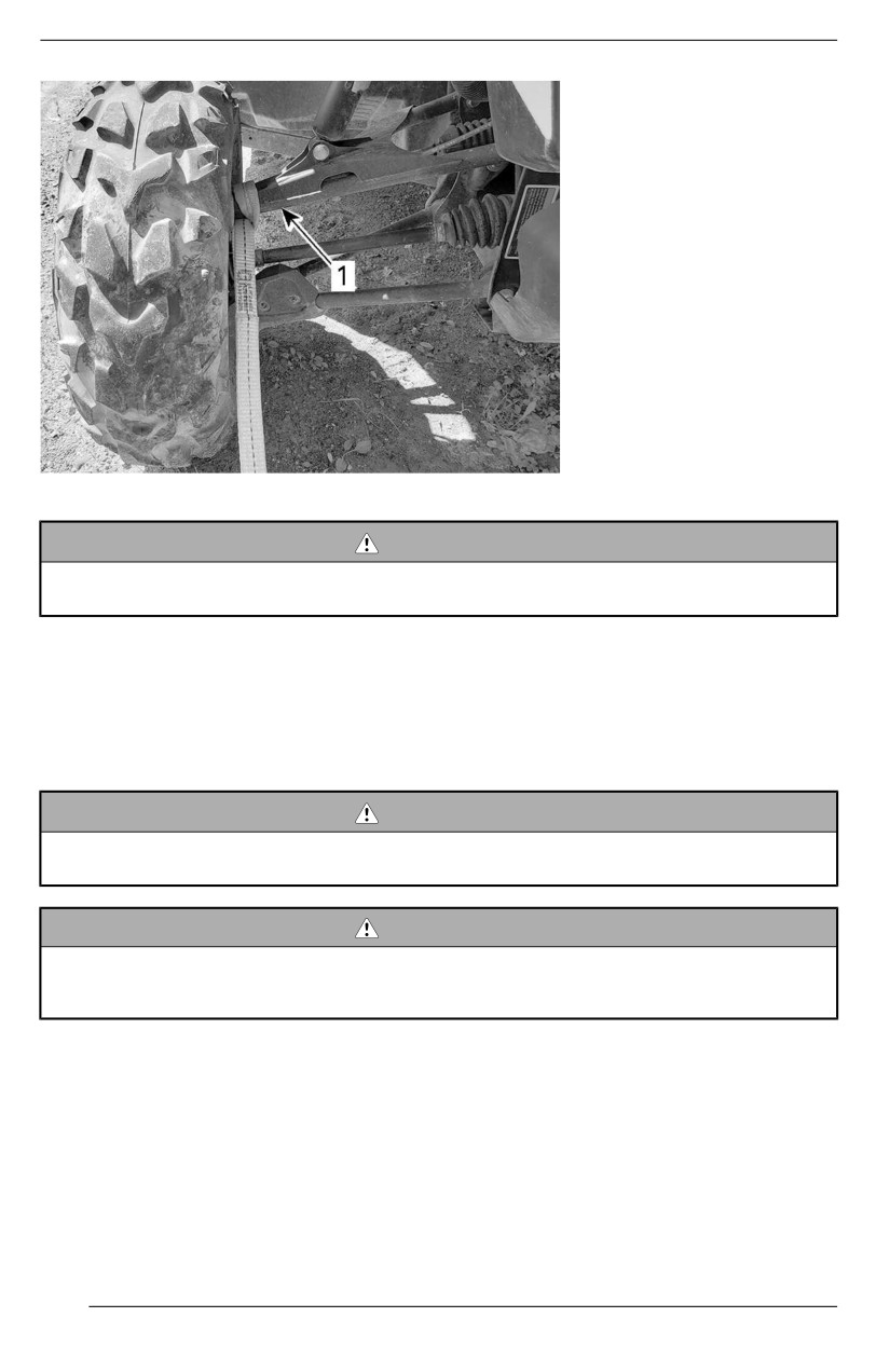
TRANSPORTING THE VEHICLE
1. Front upper suspension arm
WARNING
Ensure the brake hose is away from the strap.
A pinched brake hose may reduce the braking performance of the vehicle.
4. Strap the rear tires by using tire towing straps.
5. Firmly attach the rear suspension tie-down straps to both sides of the rear of
the trailer with ratchets.
6. Ensure that both the front and rear wheels are firmly attached to the trailer.
Getting Vehicle Out of Trailer
WARNING
Vehiicle may have moved during transport. Ensure vehicle iis properly
alligned wiith ramps before proceediing.
WARNING
Visibiiliity willl be greatlly reduced when backiing off from the traiiler. Have
the hellp of an assiistant to ensure proper allignment and safe
environment.
120
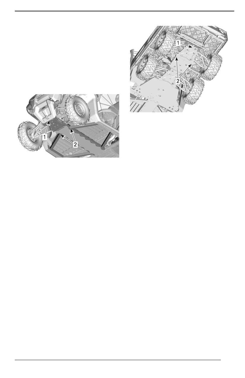
LIFTING AND SUPPORTING THE VEHICLE
Front of Vehicle
1. Place vehicle on a flat non slippery
ground.
2. Ensure vehicle shift lever is set to
PARK.
3. Install an hydraulic jack under the
front skid plate.
4. Lift front of vehicle and install a
jack stand on each side under
frame section.
1.
Lifting location under trailer hitch
2.
Frame section to install jack stands under
6.
Lower hydraulic lift and ensure ve-
hicle is supported safely onto both
jack stands.
1. Front of vehicle
2. Frame section
5. Lower hydraulic lift and ensure ve-
hicle is supported safely onto both
jack stands.
Rear of Vehicle
1. Place vehicle on a flat non slippery
ground.
2. Activate the 6WD mode.
3. Ensure vehicle shift lever is set to
PARK.
4. Install an hydraulic jack under the
skid plate.
5. Lift rear of vehicle and install a jack
stand on each side under frame
section in front of rear wheel.
121
LIFTING AND SUPPORTING THE VEHICLE
This page is intentionally blank
122
MAINTENANCE
123
MAINTENANCE SCHEDULE
Maintenance is very important to keep your vehicle in safe operating condition.
The vehicle should be serviced as per the maintenance schedule.
Proper maintenance is the owner’s responsibility. A warranty claim may be de-
nied if, among other things, the owner or operator caused the problem through
improper maintenance or use.
Perform periodic checks and follow the maintenance schedule. The maiinte-
nance schedule does not exempt the pre-ride inspection.
WARNING
Faiilure to properly maiintain the vehiclle accordiing to the maiintenance
schedulle and procedures can make it unsafe to operate.
EPA Regulation - Canadian and USA Vehicles
A repair shop or person of the owner''s choosing may maiintaiin, replace, or
repair emission control devices and systems. These instructions do not require
components or service by BRP or authorized Can-Am Off-road dealers.
Although an authorized Can-Am Off-road dealer has an in-depth technical knowl-
edge and tools to service your vehicle, the emission-related warranty is not con-
ditioned on the use of an authorized Can-Am Offroad dealer or any other
establishment with which BRP has a commercial relationship.
Proper maintenance is the owner’s responsibility. A warranty claim may be de-
nied if, among other things, the owner or operator caused the problem through
improper maintenance or use.
For emission-related warranty claims, BRP is limiting the diagnosis and repair of
emission-related parts to the authorized Can-Am Offroad dealers. For more infor-
mation, please refer to the US EPA Emission-Related Warranty contained in the
Warranty section.
You must follow the instructions for fuel requirements in the fueling section of this
manual. Even if gasoline containing greater than ten volume percent ethanol is
readily available, the US EPA issued a prohibition against the use of gasoline
containing greater than 10 vol% ethanol that applies to this vehicle. The use of
gasoline containing greater than 10 vol% ethanol with this engine may harm the
emission control system.
Air Filter Maintenance Guideline
Air filter maintenance should be adjusted according to riding conditions.
Air filter maintenance must be increased in frequency when riding on snow, dry
sand, dirt, gravel or similar conditions which have a high dust or particle
dispersion.
Riding in a group in these conditions will require increasing the air filter mainte-
nance frequency further.
NOTE:
Accessory filters and pre-filter are available for such conditions. Contact an au-
thorized Can-Am off-road dealer for details.
124
MAINTENANCE SCHEDULE
Severe Duty Use
If your vehicle is used in the following conditions, refer to the Severe Duty section
of the maintenance schedule.
- Repeated hauling of loads at more than 75% the maximum capacity.
- The increase workload applied to the drive system accelerates the differ-
entials, gearbox/transmission, and engine oil life. This reduces internal
component longevity if not replaced more frequently.
- Driving at excessive speeds for prolonged amount of time.
Higher than the average utility or commercial use requires more frequent fluid
and wear component replacement than trail, recreational, or occasional utility
purposes.
Extreme Cold Condiitiion
An engine that is frequently operated at or below an ambient temperature of -25 °
C (-13 °F) will require an increase in service and maintenance schedule.
Any combustion engine operated at these low ambient temperature will collect
an increased amount of condensation at every startup/warm-up.
Since the engine is not reaching operating temperatures for extended periods of
time, the oil is starting to be strongly diluted with water and gas residue (more
water content).
An engine needs to reach operating temperature, in order to be able to evaporate
condensate out of the oil.
If daily usage (work or leisure driving cycle) is similar to those mentioned below,
BRP strongly recommends changing the oil at least once a month.
Parameters of an increase in service and maintenance schedule:
- Engine not reaching the proper operating temperature during normal daily
usage
- Multiple starts and stops without reaching operating temperature
- Short idle periods
- Low RPM driving cycle in short distances without reaching operating
temperature.
NOTE:
BRP strongly recommends the installation of a block heater to help warm up the
liquids, this will also help to extend the oil lifetime.
Deep Mud / Water Use
Whether your vehicle is a X mr model or was accessorized for deep mud / water
use, this type of usage requires more frequent maintenance and inspections to
ensure debris has not infiltrated mechanical components.
If you regularly ride in deep mud or water, refer to the Deep Mud / Water section
of the maintenance schedule.
125
MAINTENANCE SCHEDULE
After every ride, be sure to perform the Post Operation Care for Deep Mud /
Water Environment .
Post Operation Care for Deep Mud / Water Enviironment
- Rinse the vehicle and its components with fresh water.
- Clean the CVT air filters.
- Drain the CVT compartment and clean if any water or mud is found.
- Inspect and clean engine air filters and engine air filter housing.
- Clean radiator.
- Visually inspect for any water accumulation in the vent hoses (fuel tank, gear-
box, front differential and rear final drive). If there is water, bring the vehicle to
your nearest authorized Can-Am off-road dealer for inspection and servicing
of main components related to the vents.
- Clean front and rear shock absorbers to prevent seal from damage by dust or
dirt.
- Clean drive shaft bellows and the propeller shaft yokes or boots.
Maintenance Schedule
Make sure to perform proper maintenance at recommended intervals as indi-
cated in the tables.
The maintenance chart intervals are based on 3 factors:
- Calendar time
- Vehicle hours
- Odometer reading.
Take in account whichever comes first to determine the maintenance threshold.
Your driving habits determines the factors you shall adhere too. For example:
- Someone who uses their vehicle every other weekend trail riding with friends
would most likely follow the odometer readiing to determine the maintenance
interval.
- Someone who uses their vehicle seldomly over the year or only on a few oc-
casions (hunting, camping) would most likely follow the callendar time to de-
termine the maintenance interval.
- Someone who uses their vehicle daily / weekly for long periods of time such
as agricultural / work would most likely follow the vehiicle hours to determine
the maintenance interval.
IMPORTANT: The following tables show the appropriate maintenance appli-
cation for the first
3 years. For subsequent years, repeat the same pattern
alternatively.
126

MAINTENANCE SCHEDULE
Regullar Maiintenance Overviiew
Calendar
Vehiiclle Hours
Odometer
Regular Duty
Years
1
200
3000 km (1900 mi)
A
2
400
6000 km (3700 mi)
A and B
3
600
9000 km (5600 mi)
A
Severe Duty and Mud/Water Maiintenance Overviiew
Severe Duty
Calendar
Vehiiclle Hours
Odometer
and Deep Mud /
Years
Water
0.5
100
1500 km (900 mi)
A+
1
200
3000 km (1900 mi)
A+ and A
1.5
300
4500 km (2800 mi)
A+
2
400
6000 km (3700 mi)
A+ and A and B
2.5
500
7500 km (4700 mi)
A+
3
600
9000 km (5600 mi)
A+ and A
127
MAINTENANCE SCHEDULE
REGULAR DUTY
A
B
A=Adjust
Every year
Every 2 years
C=Clean
or
or
I=Inspect
200 hours
400 hours
L=Lubricate
or
or
R=Replace
3000 km
6000 km
T=Torque
(1900 mi)
(3700 mi)
Air and Fuel Delivery
Engine air filter
I,
C or R
Air delivery components and function (airbox,
I, C
throttle body, ducts, clamps)*
Fuel components and function (Fuel tank cap,
I
fuel tank, hoses, clamps, leaks)*
Fuel pump pressure
I
Body, Chassis and Accessories
Cage fasteners
T
Seat belts retractors, buckles and
I, C
semi-cinching
Winch
I, C
Windshield hinge screws (if equipped)
T
Door latches, hinges and key barrels
L, T
Power tilt bed hydraulic cylinder spherical
L
bearing (If equipped)
Engine and Cooling
Engine oil and filter
R
I, A
Valve clearance (Regardless of calendar
I, A
(Mono cyl.
time)
(V-twin engines)
engines)
Spark plugs (Regardless of calendar time)
R
Engine seals and gaskets
I
Engine cooling components (Concentration,
I, A
level, hoses condition, clamps, leaks)*
R
Engine coolant
Every 5 years or 12 000 km (7500 mi)
Radiator
C
Exhaust and Emissions
Exhaust components (gaskets, pipes, muffler
I, C
condition, leaks)*
Fuel tank vent breather filter (Non EVAP
R
models)
128
MAINTENANCE SCHEDULE
REGULAR DUTY
A
B
A=Adjust
Every year
Every 2 years
C=Clean
or
or
I=Inspect
200 hours
400 hours
L=Lubricate
or
or
R=Replace
3000 km
6000 km
T=Torque
(1900 mi)
(3700 mi)
Canister vent pre-filter (CARB and EVAP
R
models)
Muffler spark arrester
C
Debris around exhaust pipe and muffler area
C
HVAC
Air filter
I, C
Heating and air conditioning components and
I, C
function*
Air conditioning compressor belt
I
Brake
Brake components and function (Fluid level,
brake pads, brake discs, calipers, lines and
I, C, L, A
master cylinder)*
R
Brake fluid
Every 2 years
Drive
Replace at first 3000 km (1900 mi) and
Gearbox oil
at 6000 km (3700 mi), then follow the
regular schedule
Gearbox oil
I, A
R
Front differential oil
I, A
R
Rear final drive oil (Mono-cyl. engine)
I
R
Middle and rear differential oil (6x6 models)
I, A
R
Tires (Wear, pressure)
I, A
Wheel lug nuts
T
Beadlock screws (if equipped)
T
Drive components and function*
I
Controls
Gearbox lever operation
I, A
Throttle operation
I
Continuously Variable Transmission (CVT)
CVT components and function*
I, C, L
129
MAINTENANCE SCHEDULE
REGULAR DUTY
A
B
A=Adjust
Every year
Every 2 years
C=Clean
or
or
I=Inspect
200 hours
400 hours
L=Lubricate
or
or
R=Replace
3000 km
6000 km
T=Torque
(1900 mi)
(3700 mi)
Slide shoes in driven pulley (Mono-cyl.
R
engine)
Electrical
Battery connections and condition
I, C
Modules fault codes and applicable software
I
updates
Operation of controls switches and lighting*
I
Vehicle speed sensor (VSS) (Mono-cyl.
C
engine)
Steering
Steering components and function*
I
Suspension
Suspension components and function*
I, C, L, T
I, L
Recommended at
Stabilizer bar bushings
every 1000 km
(620 mi)
* For an extensive list of maintenance actions to be performed, refer to your local
dealership.
130
MAINTENANCE SCHEDULE
SEVERE DUTY
A+
A
B
Every 6
Every 2
A=Adjust
Every year
months
years
C=Clean
or
or
or
I=Inspect
200 hours
100 hours
400 hours
L=Lubricate
or
or
or
R=Replace
3000 km
1500 km
6000 km
T=Torque
(1900 mi)
(900 mi)
(3700
mi)
Air and Fuel Delivery
Engine air filter
I,
C
R
Air delivery components and
function (airbox, throttle body, ducts,
I,
C
clamps)*
Fuel components and function (Fuel
tank cap, fuel tank, hoses, clamps,
I
leaks)*
Fuel pump pressure
I
Body, Chassis and Accessories
Cage fasteners
T
Seat belts retractors, buckles and
I, C
semi-cinching
Winch
I,
C
Windshield hinge screws (if
T
equipped)
Door latches, hinges and key barrels
L, T
Power tilt bed hydraulic cylinder
L
spherical bearing (If equipped)
Engine and Cooling
Engine oil and filter
R
I, A
I, A
Valve clearance (Regardless of
(V-twin
(Mono cyl.
calendar time)
engines)
engines)
Spark plugs (Regardless of calendar
R
time)
Engine seals and gaskets
I
Engine cooling components
(Concentration, level, hoses
I, A
I
condition, clamps, leaks)*
R
Engine coolant
Every 5
years or 12 000 km (7500 mi)
Radiator
C
Exhaust and Emissions
131
MAINTENANCE SCHEDULE
SEVERE DUTY
A+
A
B
Every 6
Every 2
A=Adjust
Every year
months
years
C=Clean
or
or
or
I=Inspect
200 hours
100 hours
400 hours
L=Lubricate
or
or
or
R=Replace
3000 km
1500 km
6000 km
T=Torque
(1900 mi)
(900 mi)
(3700
mi)
Fuel tank vent breather filter (Non
R
EVAP models)
Canister vent pre-filter (CARB and
R
EVAP models)
Exhaust components (gasket, pipes,
I, C
muffler condition, leaks)*
Muffler spark arrester
C
Debris around exhaust pipe and
C
muffler area
HVAC
Air filter
I, C
Heating and air conditioning
I, C
components and function*
Air conditioning compressor belt
I
Brake
Brake components and function
(Fluid level, brake pads, brake discs,
I,
C, L, A
calipers, lines and master cylinder)*
R
Brake fluid
Every 2 years
Drive
Replace at first
1500 km (900 mi) and at 3000
Gearbox oil and filter
km (1900 mi), then follow the regular schedule
Gearbox oil and filter
I, A
R
Front differential oil
I, A
R
Rear final drive oil (Mono-cyl.
I, A
R
engine)
Middle and rear differential oil (6x6
I, A
R
models)
Tires (Wear, pressure)
I, A
Wheel lug nuts
T
Beadlock screws (if equipped)
T
Drive components and function*
I
132
MAINTENANCE SCHEDULE
SEVERE DUTY
A+
A
B
Every 6
Every 2
A=Adjust
Every year
months
years
C=Clean
or
or
or
I=Inspect
200 hours
100 hours
400 hours
L=Lubricate
or
or
or
R=Replace
3000 km
1500 km
6000 km
T=Torque
(1900 mi)
(900 mi)
(3700
mi)
Controls
Gearbox lever operation
I, A
Throttle operation
I
Continuously Variable Transmission (CVT)
CVT components and function*
I, C, L
Slide shoes in driven pulley
R
(Mono-cyl. engine)
Electrical
Battery connections and condition
I, C
Modules fault codes and applicable
I
software updates
Operation of controls switches and
I
lighting*
Vehicle speed sensor (VSS)
C
(Mono-cyl. engine)
Steering
Steering components and function*
I
Suspension
Suspension components and
I,
C, L
T
function*
I, L
Recommend-
Stabilizer bar bushings
ed at
every1000 km
(620 mi)
* For an extensive list of maintenance actions to be performed, refer to your local
dealership.
133
MAINTENANCE SCHEDULE
DEEP MUD / WATER
A+
A
B
Every 6
Every 2
A=Adjust
Every year
months
years
C=Clean
or
or
or
I=Inspect
200 hours
100 hours
400 hours
L=Lubricate
or
or
or
R=Replace
3000 km
1500 km
6000 km
T=Torque
(1900 mi)
(900 mi)
(3700
mi)
Air and Fuel Delivery
Engine air filter
I,
C
R
Air delivery components and
function (airbox, throttle body, ducts,
I,
C
clamps)*
Fuel components and function (Fuel
tank cap, fuel tank, hoses, clamps,
I
leaks)*
Fuel pump pressure
I
Body, Chassis and Accessories
Cage fasteners
T
Seat belts retractors, buckles and
I, C
semi-cinching
Winch
I,
C
Windshield hinge screws
T
Door latches, hinges and key barrels
L, T
Power tilt bed hydraulic cylinder
L
spherical bearing (If equipped)
Engine and Cooling
Engine oil and filter
I,
A
R
I, A
I, A
Valve clearance (Regardless of
(V-twin
(Mono cyl.
calendar time)
engines)
engines)
Spark plugs (Regardless of calendar
R
time)
Engine seals and gaskets
I
Engine cooling components
(Concentration, level, hoses
I, A
condition, clamps, leaks)*
R
Engine coolant
Every 5
years or 12 000 km (7500 mi)
Radiator
C
Exhaust and Emissions
134
MAINTENANCE SCHEDULE
DEEP MUD / WATER
A+
A
B
Every 6
Every 2
A=Adjust
Every year
months
years
C=Clean
or
or
or
I=Inspect
200 hours
100 hours
400 hours
L=Lubricate
or
or
or
R=Replace
3000 km
1500 km
6000 km
T=Torque
(1900 mi)
(900 mi)
(3700
mi)
Fuel tank vent breather filter (Non
R
EVAP models)
Canister vent pre-filter (CARB and
R
EVAP models)
Exhaust components (gasket, pipes,
I, C
muffler condition, leaks)*
Muffler spark arrester
C
Debris around exhaust pipe and
C
muffler area
HVAC
Air filter
I, C
Heating and air conditioning
I, C
components and function*
Air conditioning compressor belt
I
Brake
Brake components and function
(Fluid level, brake pads, brake discs,
I,
C, L, A
calipers, lines and master cylinder)*
R
Brake fluid
Every 2 years
Drive
Replace at first
1500 km (900 mi) and at 3000
Gearbox oil and filter
km (1900 mi), then follow the regular schedule
Gearbox oil and filter
I, A
R
Front differential oil
I, A
R
Rear final drive oil (Mono-cyl.
I, A
R
engine)
Middle and rear differential oil (6x6
I, A
R
models)
Tires (Wear, pressure)
I, A
Wheel lug nuts
T
Beadlock screws (if equipped)
T
Drive components and function*
I
135
MAINTENANCE SCHEDULE
DEEP MUD / WATER
A+
A
B
Every 6
Every 2
A=Adjust
Every year
months
years
C=Clean
or
or
or
I=Inspect
200 hours
100 hours
400 hours
L=Lubricate
or
or
or
R=Replace
3000 km
1500 km
6000 km
T=Torque
(1900 mi)
(900 mi)
(3700
mi)
Controls
Gearbox lever operation
I, A
Throttle operation
I
Continuously Variable Transmission (CVT)
CVT components and function*
I, C, L
Slide shoes in driven pulley
R
(Mono-cyl. engine)
Electrical
Battery connections and condition
I, C
Modules fault codes and applicable
I
software updates
Operation of controls switches and
I
lighting*
Vehicle speed sensor (VSS)
C
(Mono-cyl. engine)
Steering
Steering components and function*
I
Suspension
Suspension components and
I,
C, L
T
function*
I, L
Recommend-
Stabilizer bar bushings
ed at every
1000 km (620
mi)
* For an extensive list of maintenance actions to be performed, refer to your local
dealership.
136

MAINTENANCE SCHEDULE
Maintenance Records
Send photocopy of maintenance record to BRP if needed.
Pre-delivery
Serial number:
Signature/Print:
Mileage / km:
Hours:
Date:
Dealer no:
Notes:
Refer to vehicle Pre-Delivery Bulletin for detailed installation procedures
FIRST inspection
Mileage / km:
Signature/Print:
Hours:
Date:
Dealer no:
Notes:
For maintenance schedule refer to Maintenance Information section of this operator's guide
Service
Mileage / km:
Signature/Print:
Hours:
Date:
Dealer no:
Notes:
For maintenance schedule refer to Maintenance Information section of this operator's guide
137

MAINTENANCE SCHEDULE
Service
Mileage / km:
Signature/Print:
Hours:
Date:
Dealer no:
Notes:
For maintenance schedule refer to Maintenance Information section of this operator's guide
Service
Mileage / km:
Signature/Print:
Hours:
Date:
Dealer no:
Notes:
For maintenance schedule refer to Maintenance Information section of this operator's guide
Service
Mileage / km:
Signature/Print:
Hours:
Date:
Dealer no:
Notes:
For maintenance schedule refer to Maintenance Information section of this operator's guide
138

MAINTENANCE SCHEDULE
Service
Mileage / km:
Signature/Print:
Hours:
Date:
Dealer no:
Notes:
For maintenance schedule refer to Maintenance Information section of this operator's guide
Service
Mileage / km:
Signature/Print:
Hours:
Date:
Dealer no:
Notes:
For maintenance schedule refer to Maintenance Information section of this operator's guide
Service
Mileage / km:
Signature/Print:
Hours:
Date:
Dealer no:
Notes:
For maintenance schedule refer to Maintenance Information section of this operator's guide
139

MAINTENANCE SCHEDULE
Service
Mileage / km:
Signature/Print:
Hours:
Date:
Dealer no:
Notes:
For maintenance schedule refer to Maintenance Information section of this operator's guide
Service
Mileage / km:
Signature/Print:
Hours:
Date:
Dealer no:
Notes:
For maintenance schedule refer to Maintenance Information section of this operator's guide
Service
Mileage / km:
Signature/Print:
Hours:
Date:
Dealer no:
Notes:
For maintenance schedule refer to Maintenance Information section of this operator's guide
140

MAINTENANCE SCHEDULE
Service
Mileage / km:
Signature/Print:
Hours:
Date:
Dealer no:
Notes:
For maintenance schedule refer to Maintenance Information section of this operator's guide
Service
Mileage / km:
Signature/Print:
Hours:
Date:
Dealer no:
Notes:
For maintenance schedule refer to Maintenance Information section of this operator's guide
Service
Mileage / km:
Signature/Print:
Hours:
Date:
Dealer no:
Notes:
For maintenance schedule refer to Maintenance Information section of this operator's guide
141
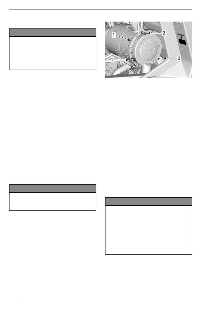
MAINTENANCE PROCEDURES
ENGINE AIR FILTER
NOTICE
Never modiify the aiir intake sys-
tem. Otherwise, engine perform-
ance degradatiion or damage can
occur. The engiine is callibrated to
operate speciifiicallly with these
components.
Engiine Air Fiilter Repllacement
1. Air filter cover
Guideliine
2. Latches
Engine air filter inspection and re-
placement frequency should be ad-
The filter fits tightly over the outlet
justed according to riding conditions
tube and there will be some initial re-
as it is critical to ensure proper engine
sistance. Gently move the end of the
performance and life span.
filter back and forth to break the seal,
then rotate while pulling straight out.
Engine air filter inspection and re-
Avoid knocking the filter against the
placement frequency must be in-
housing.
creased for the following severe riding
conditions:
Clleaniing the Engine Aiir Fillter
- Riding on dry sand.
1. Inspect the filter for any signs of
- Riding on dry dirt covered
leaks. A streak of dust on the clean
surfaces.
side of the filter is a telltale sign.
- Riding on dry gravel trails or simi-
Replace filter if there is any dam-
lar conditions.
ages. Eliminate any source of air
- Riding in areas with high concen-
leaks before installing a new filter.
tration of seeds or crop husks.
2. Clean engine air filter by tapping
- Riding in severe snow conditions.
out heavy dust from paper ele-
ment, this will allow dirt and dust to
NOTICE
get out of the paper filter.
When riding iin dusty condiitiions or
sand, the air box needs to be
NOTICE
clleaned before every ride.
It iis not recommended to blow
compressed air on the paper ele-
NOTE:
ment; this coulld damage the pa-
Riding in a group, under these condi-
per fiibers and reduce its fiiltratiion
tions, increases the frequency of the
abiiliity when used in dusty envi-
air filter maintenance.
ronments. If engiine aiir fillter iis too
dirty and cannot be clleaned foll-
Removiing the Engine Aiir Fillter
lowing the recommended proce-
dure, iit shoulld be repllaced.
Tilt the cargo box.
Unlatch air filter cover and remove air
3. Inspect air filter housing for cleanli-
filter.
ness. Clean if necessary.
4. Use a clean damp cloth to wipe
both the filter sealing surface and
the inside of the inlet tube. Ensure
142
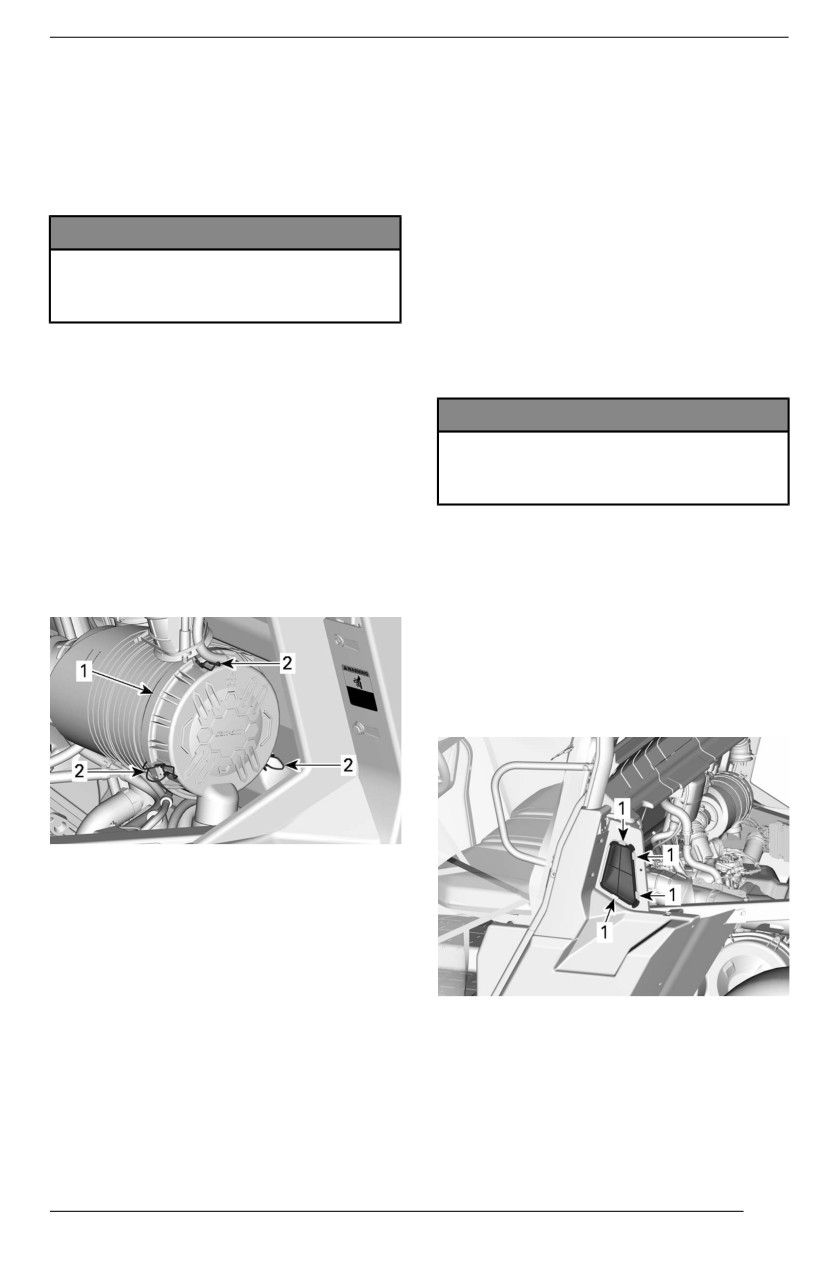
MAINTENANCE PROCEDURES
that the inlet tube sealing area is
critical to ensure proper engine per-
undamaged.
formance and life span.
Under the following severe riding con-
Duckbiilll Valve Cleaning
ditions, the inspection and replace-
Visually check and physically squeeze
ment frequency must be increased:
the duckbill valve.
- Riding on dry sand.
- Riding on dry dirt covered
NOTICE
surfaces.
Make sure the duckbill vallve iis
- Riding on dry gravel trails or simi-
flexible and not iinverted, dam-
lar conditions.
aged or plugged.
- Riding in muddy conditions.
- Riding in areas with high concen-
Installliing the Engine Aiir Fiilter
tration of seeds or crop husks.
- Riding in severe snow conditions.
1. Insert the filter carefully.
2. Seat the filter by hand, making cer-
NOTICE
tain it is inserted completely into
the air cleaner housing.
When riding iin dusty condiitiions or
3. Apply pressure by hand at the out-
sand, the aiir fillter needs to be
er rim of the filter, not the flexible
clleaned before every ride.
center.
4. Inspect and carefully clean gasket
NOTE:
in the groove of the cover. Replace
Riding in a group, under these condi-
if damaged.
tions, increases the frequency of the
5. Secure air filter cover with latches.
air filter maintenance.
Removiing the Priimary CVT Air
Fiilter
1. Tilt the cargo box.
2. Press the filter tabs to release it.
1. Air filter cover
2. Latches
6. Install the air filter access door
back in place and secure it with the
quarter-turn screw.
CVT Air Filter
1. Press here
CVT Aiir Fiilter Replacement
3. Remove the CVT air filter.
Guiideline
Removiing the Secondary CVT Aiir
CVT air filter inspection and replace-
Fiilter (If equipped)
ment frequency should be adjusted
according to riding conditions as it is
1. Tilt the cargo box.
143
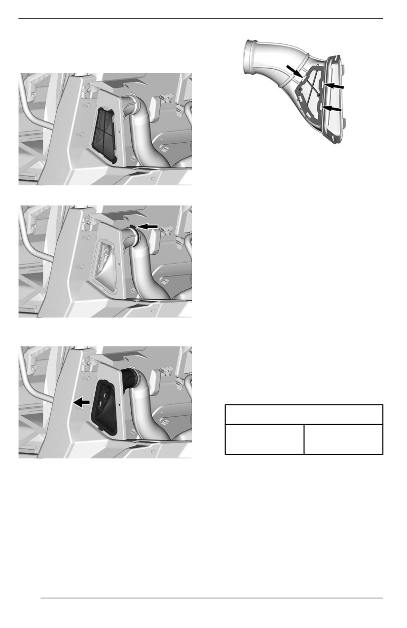
MAINTENANCE PROCEDURES
2. Remove the primary CVT filter.
Refer to Removing the Primary
CVT Air Filter.
6. Remove the CVT air filter.
Inspecting and Cleaning the CVT
Air Fillter
3.
Loosen the clamp.
1. Inspect filter and replace if
damaged.
2. Clean filter using a solution of soft
soap and water, then rinse.
3. Gently shake off excess water and
allow filter to dry at room
temperature.
4. Clean inside the CVT air inlet with
a vacuum cleaner.
Installliing the Priimary CVT Air Fillter
1. Reinstall the primary CVT air filter.
4.
Remove
filter
housing
from
the
2. Lower and lock the cargo box.
vehicle.
Installliing the Secondary CVT Aiir
Fillter
1. The installation is the reverse of
the removal procedure. However
pay attention to the following.
Tightening Torque
2 ± 0.3 Nm
Gear clamp
(17 ± 3 lbf-in)
5.
Press the filter tabs to release it.
Evaporative Emission
System Pre-Filter (If
Equipped)
Evaporative Emission System
Pre-Fillter Replacement
1. Tilt the cargo box.
2. Remove the hose clamps.
3. Remove the retaining screws.
144
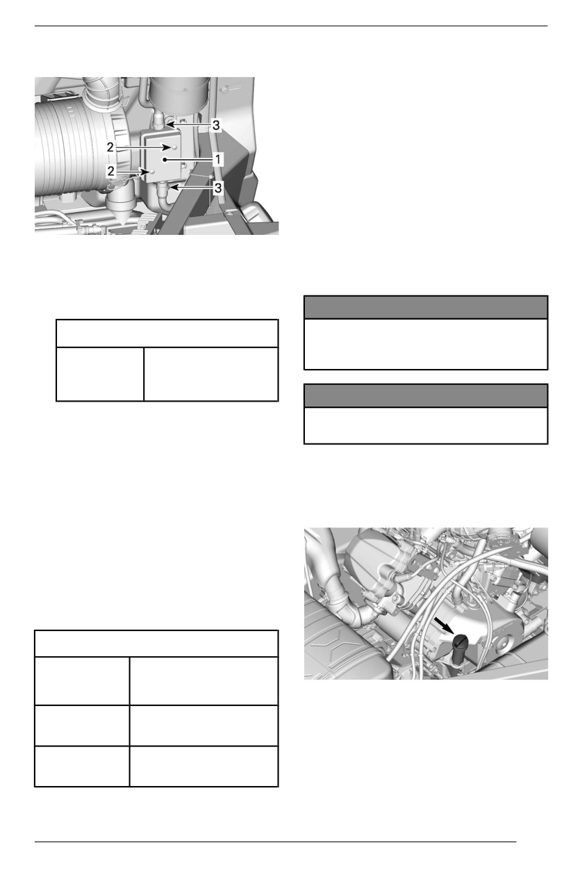
MAINTENANCE PROCEDURES
4.
Remove the pre-filter assembly.
If the recommended XPS engine oil is
not available:
- Use a 4-stroke SAE engine syn-
thetic or synthetic blend oil meet-
ing or exceeding the following
lubricant industry specifications.
- Always check the API service label
certification on the oil container, it
must contain at least one of the in-
dicated standards.
- API service cllassifiication
SN, or
- JASO MA2
1.
Pre-Filter
2.
Retaining screw
Veriifyiing the Engine Oill Level
3.
Clamps
(V-Twiin)
5.
Install a new pre-filter assembly.
NOTICE
Operatiing the engiine wiith an im-
Tiightening Torque
proper level may severely dam-
Pre-filter
age engiine.
2.5 ± 0.5 Nm
retaining
(22 ± 4 lbf-in)
screw
NOTICE
6.
Secure hoses with clamps.
Check the oiil llevell when the en-
7.
Install all other removed parts.
giine iis COLD.
ENGINE OIL
1.
Place vehicle on a level surface.
Recommended Engine Oill
2.
Clean around dipstick to avoid for-
eign particles falling down the
Rotax® engines were developed and
tube.
validated using the XPS® oil.
BRP recommends the use of its XPS
engine oil or an equivalent at all time.
Damage caused by the use of an oil
not suitable for the engine may not be
covered by the BRP Limited Warranty.
XPS Recommended Engine Oil
General
5W40 synthetic blend
purpose
3.
Unscrew dipstick then remove it
oil
and wipe clean.
Cold
4.
Reinstall dipstick, screw in it
temperature
0W40 synthetic oil
completely.
5.
Remove dipstick and check oil lev-
Warm
el. It should be near or equal to the
temperature
10W50 synthetic oil
upper mark.
145
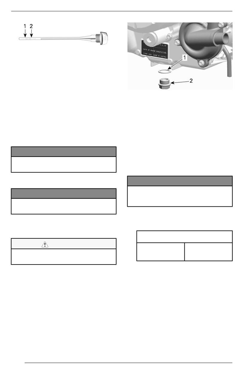
MAINTENANCE PROCEDURES
1. MIN
2. MAX
If the level is between marks, rein-
stall the dipstick.
If the level is below the lower mark,
add oil as follow:
1. Gasket ring (discard)
2. Drain plug
- Place a funnel into the dipstick
hole.
7. Allow oil to drain completely from
- Add a small amount of recom-
the crankcase.
mended oil and recheck oil
8. Clean the magnetic drain plug
level.
from metal shavings and residue.
- Continue to add oil until the lev-
el reaches the upper mark.
NOTE: Presence of debris gives an
indication of internal engine damage.
NOTICE
Do not overfiilll. Wiipe off any
9. Install a NEW gasket ring on the
spilllage.
drain plug.
Changiing the Engine Oil
NOTICE
Never use the gasket riing a sec-
NOTICE
ond tiime. Always replace with a
Engiine oiil and oill fiilter must be re-
new one.
pllaced at the same tiime.
10. Install and tighten drain plug to the
Oil change and oil filter replacement
recommended specification.
should be done with a warm engine.
Tighteniing Torque
CAUTION
30 ± 2 Nm
Drain plug
The engine oill can be very hot.
(22 ± 1 lbf-ft)
Wait untill engine oill iis warm.
11. Replace oil filter, refer to Oil Filter.
12. Refill engine, refer to Recom-
1. Place the vehicle on a level
mended Engine Oil.
surface.
2. Clean the dipstick area.
NOTE: For engine oil capacity, refer
3. Remove the dipstick.
to Technical Specifications.
4. Place a drain pan under the engine
drain plug area.
13. Start engine and let it idle for a 60
5. Clean the drain plug area.
seconds.
6. Unscrew drain plug and discard
14. Stop engine.
the gasket ring.
15. Check the oil level immediately, re-
fer to Verifying the Engine Oil
Level.
146
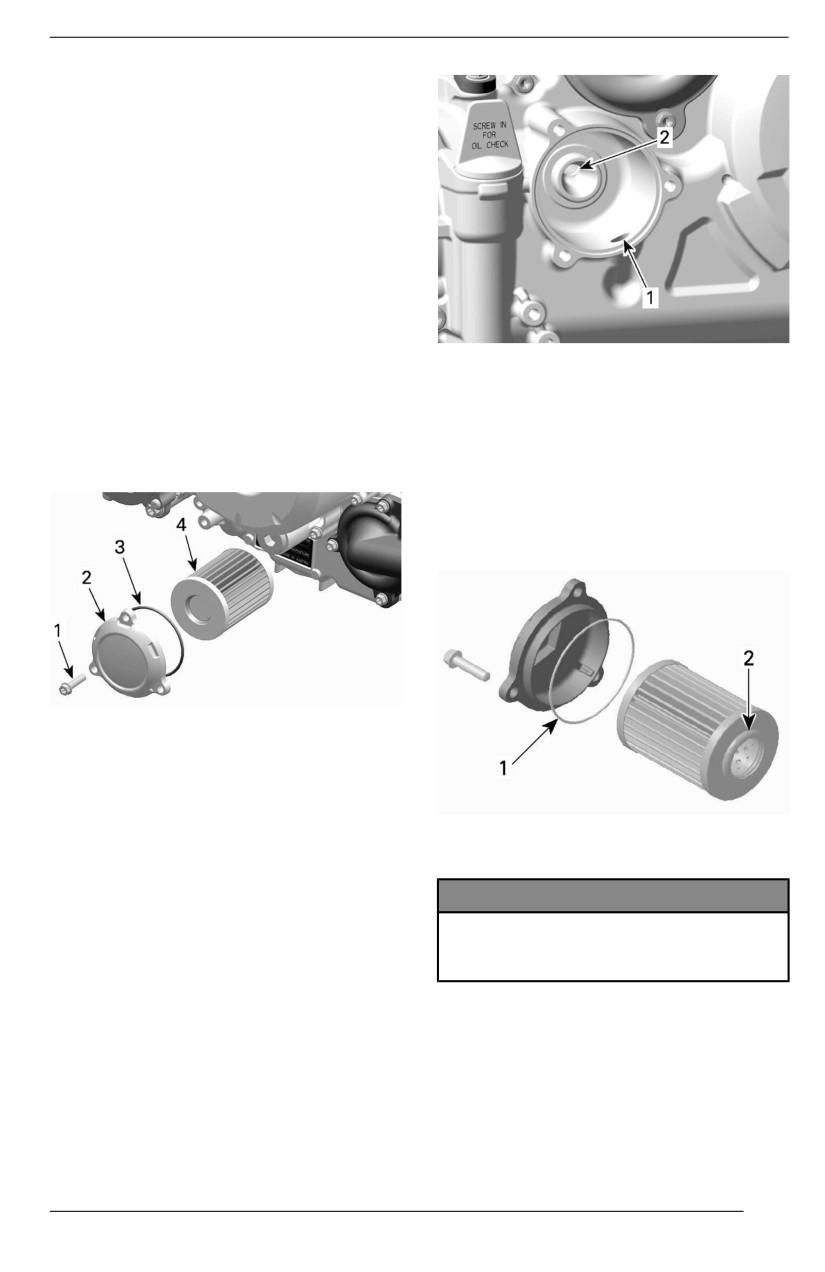
MAINTENANCE PROCEDURES
16. Refill as necessary.
17. Ensure oil filter and drain plug
areas are not leaking.
18. Dispose oil and filter as per your
local environmental regulations.
Oil Filter
Removing the Oiil Fiilter
1. Tilt the cargo box.
NOTE:
The oil filter cover can also be
1.
Inlet bore from the oil pump to the oil filter
reached by removing the passenger
2.
Outlet bore to the engine oil providing
seats and the engine service cover.
system
2. Clean oil filter area.
3. Remove oil filter cover.
2.
Wet a NEW O-ring with engine oil
4. Remove and discard oil filter.
and slip onto oil filter cover.
3.
Install the new filter into the cover.
4.
Apply engine oil to the seal on the
open end of the oil filter.
TYPICAL
1. Oil filter screw
2. Oil filter cover
3. O-ring
4. Oil filter
1. Slightly oil
Installliing the Oill Fiilter
2. Slightly oil
1. Check and clean the oil filter inlet
and outlet area for dirt and other
NOTICE
contaminations.
Pay attention to avoid pinching
the O-ring duriing fiilter and cover
i
installlatiion.
5. Install the cover on the engine.
6. Tighten oil filter cover screws to
recommended specification.
147
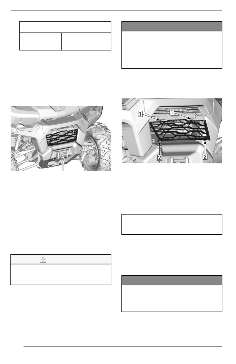
MAINTENANCE PROCEDURES
Tighteniing Torque
NOTICE
Be careful not to damage the radi-
Oil filter cover
10 ± 1 Nm
ator fins when cleaning. Do not
screws
(89 ± 9 lbf-in)
use any objject/tool that could
7. Wipe off any oil spillage on engine.
damage the fiins. When hosiing,
use llow pressure onlly. Never use
a HIGH PRESSURE washer.
RADIATOR
Inspectiing and Cleaning the
4. To install the front grille, insert the
Radiiator
upper tabs first and push bottom of
grille in the front fascia.
Periodically check the radiator area
for cleanliness.
1. Insert upper tabs
2. Push and lock lower tabs in fascia
1. To access radiator, pull the lower
part of the front grille and slide it
ENGINE COOLANT
down.
2. Inspect radiator and hoses for
Recommended Engine Coollant
leaks or any damage.
3. Inspect radiator fins. They must be
1. XPS recommended coolant
clean, free of mud, dirt, leaves or
any other deposit that would pre-
XPS Extended liife pre-mixed
vent air from passing freely trough
coolant
the radiator.
If available, use a garden hose to
Alternative, or if the XPS product is
rinse the radiator fins.
not available.
- Distilled water and antifreeze
CAUTION
solution (50% distilled water,
Never cllean radiator wiith your
50% antifreeze)
hands when it iis hot. Let the radia-
tor cooll down before cleaning.
NOTICE
Allways use ethylene-glycoll antii-
freeze containing corrosion iinhiibi-
tors speciifiicallly for internal
combustiion alluminum engines.
148
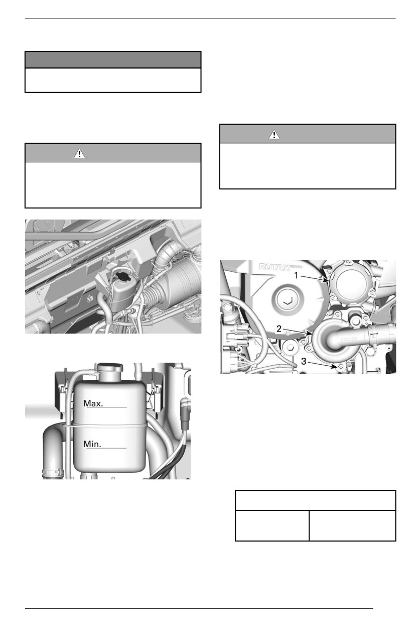
MAINTENANCE PROCEDURES
Verifying the Engiine Coolant Level
4. Close the cargo box.
NOTICE
NOTE:
Check coolant level with engiine
A cooling system that frequently re-
cold.
quires addition of coolant is an indica-
tion of leaks or engine problems.
1. Place vehicle on a level surface.
Repllaciing the Engine Coollant
2. Open the cargo box.
3. Remove the pressure cap
WARNING
In order to avoiid potentiial burns,
WARNING
do not remove the pressure cap or
In order to avoid potentiall burns,
l
loosen the coolant drain pllug iif
do not remove the pressure cap or
the engiine iis hot.
l
loosen the coollant drain plug if
the engine is hot.
1. Remove the cooling system pres-
sure cap.
2. Unscrew coolant drain plug parti-
ally to drain the coolant into a suit-
able container.
4. Ensure cooling system is full up to
the Max line.
V-TWIN ENGINE
1. Oil filter cover
2. Water pump cover
3. Coolant drain plug
3. Disconnect the lower radiator hose
from the water pump cover and
drain the remaining coolant into a
suitable container.
4. Tighten the coolant drain plug to
specification.
Adding Coollant
Tightening Torque
1. Remove the coolant tank pressure
cap.
Coolant drain
10 ± 1 Nm
2. Using a funnel to avoid spillage,
plug
(89 ± 9 lbf-in)
add coolant in system as neces-
5. Reinstall radiator hose.
sary. Do not overfiilll.
3. Properly reinstall pressure cap on
cooling tank.
149
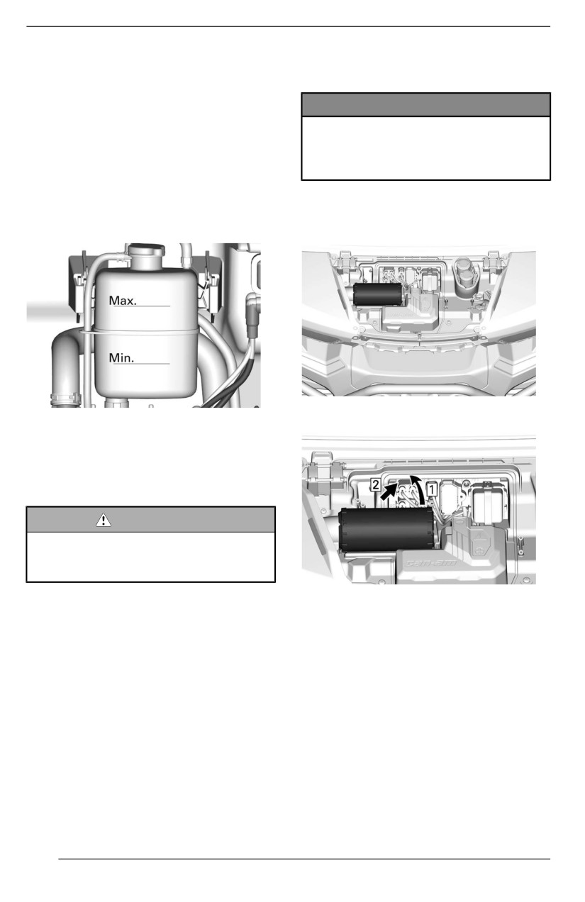
MAINTENANCE PROCEDURES
6. Fill cooling system with coolant, re-
Heating/Air Conditioning Air
fer to Bleeding the Cooling System
Filter (if equipped)
procedure.
NOTICE
Bleediing the Coolling System
The clleaniing of the fiilters must be
1. On models equiipped with heater
performed more often than recom-
or HVAC: Put the fan speed to
mended when riiding in dusty con-
MAX and raise the temperature
ditions or sand.
control to the maximum.
2. Remove the pressure cap.
Fresh Aiir Fiilter
3. Fill coolant system until it is full up
to the Max line on the coolant tank.
Open hood to access fresh air filter.
4. Install pressure cap.
Lift and slide filter to remove.
5. Run engine at idle with the pres-
sure cap ON until the cooling fan
cycles on for a second time.
6. Stop the engine and let it cool
down.
WARNING
In order to avoiid potentiial burns,
do not remove the pressure cap iif
the engiine iis hot.
1. Lift
7. When the engine is cool, remove
2. Slide
pressure cap and add coolant if
required.
Inspect the filter for any signs of leaks.
8. Install pressure cap.
A streak of dust on the clean side of
9. After the next ride, following this
the filter is a telltale sign. Replace filter
procedure, check coolant level.
if there is any damages. Eliminate any
Add coolant as required. Refer to
source of air leaks before installing a
Verifying the Engine Coolant
new filter.
Level.
Clean air filter by tapping out heavy
dust from paper element, this will al-
low dirt and dust to get out of the pa-
per filter.
150
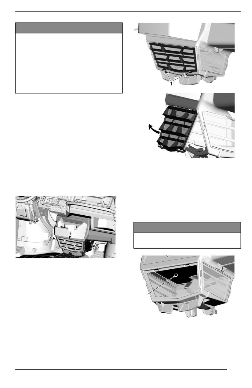
MAINTENANCE PROCEDURES
NOTICE
It is not recommended to bllow
compressed aiir on the paper ele-
ment; this coulld damage the pa-
per fiibers and reduce its fiiltration
abillity when used in dusty envii-
ronments. If air fiilter is too diirty
and cannot be cleaned folllowing
the recommended procedure, iit
shoulld be replaced.
Use a clean damp cloth to wipe both
the filter sealing surface and the inside
of the outlet tube. Ensure that the out-
let tube sealing area is undamaged.
The installation is the reverse of the
removal procedure.
Cockpiit Air fiilters
Cockpit air filters are located at the
bottom of the center console. There
Clean air filter by washing it in luke-
are 3 filters:
warm water with mild soap. Remove
excess water and air dry before
- One at the front of the unit
installation.
- One on each side of the unit.
Before installing the filter, clean the in-
side of the heating/air conditioning
unit and the evaporator coil using vac-
uum and a soft brush.
1
NOTICE
3
Be carefull when brushiing to avoiid
damaging the evaporator coiil fins.
2
1. Front cockpit air filter
2. Lateral cockpit air filter - passenger side
3. Lateral cockpit air filter - driver side
Front Cockpit Air Fiilter
1
To remove this filter, lift the grille tabs
and pull up.
1. Evaporator
The installation is the reverse of the
removal procedure.
151
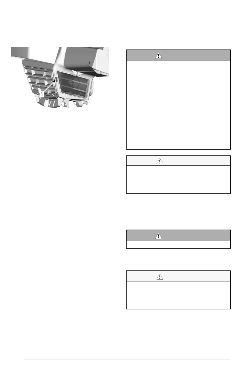
MAINTENANCE PROCEDURES
Laterall Cockpiit Air Fillters
EXHAUST SYSTEM
To remove these filters, grab the grille
tab and pull.
Clleaniing the Area Surrounding the
Exhaust System
WARNING
Debriis accumullatiion could llead to
a vehiclle fiire when the exhaust
system is hot and the debriis are
dried.
In some cases, that could resullt in
seriious properlly damages, iinju-
ries or even death.
Clean often and regullarly the area
1. Grille tab
surrounding the exhaust system
when ridiing iin swamp, bog, hay or
Clean air filters by washing them in
dead lleaves.
lukewarm water with mild soap. Re-
In other siituations, cllean as per
move excess water and air dry before
maintenance schedulle
installation.
requiirement.
The installation is the reverse of the
removal procedure.
CAUTION
Never perform this operation iim-
Air Conditioning Compressor
mediatelly after the engine has
Belt
been running because exhaust
system is very hot.
Visually inspect the compressor belt
for wear.
1. From the rear of the vehicle, clean
Hairline cracks do not require the re-
the areas around the muffler.
placement of the belt, but must be
2. Clean the areas around the ex-
monitored closely. Damage to the
haust pipe.
center of the belt will eventually re-
quire belt replacement, but when
WARNING
cracks extend to the edge of the belt,
the belt failure is imminent.
Clean allso under the heat shields.
The compressor belt tension verifica-
Inspecting and Cleaning the
tion and belt replacement should be
Muffler Spark Arrester
performed by an authorized Can-Am
Off-Road dealer according to the
CAUTION
Maintenance Schedule.
Never perform this operation iim-
mediatelly after the engine has
been running as exhaust system
is very hot.
1. Remove and discard the tail pipe
retaining screws.
152
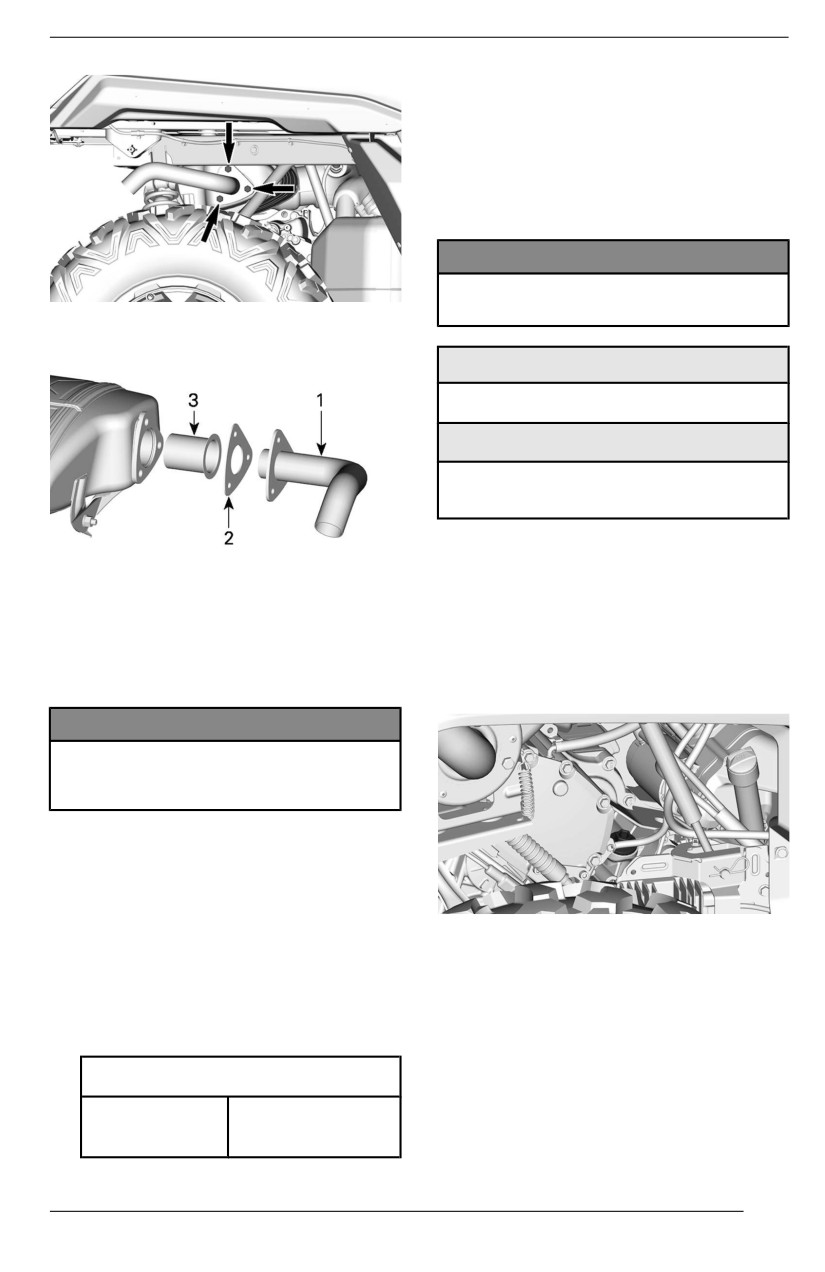
MAINTENANCE PROCEDURES
GEARBOX
Recommended Gearbox Oiil
The XPS oil is specially formulated to
meet the lubrication requirements of
this gearbox. BRP strongly recom-
mends the use of its XPS oil.
NOTICE
Do not use another type of oill
when servicing.
2.
Remove exhaust tail pipe, gasket
(discard) and spark arrester.
XPS Recommended Gearbox Oiil
75W140 Synthetic gear oil
Allternatiive, or if not availlable
75W 140 API GL-5 Synthetic gear
oil
Veriifyiing the Gearbox Oiil Levell
TYPICAL
(V-Twiin)
1. Tail pipe
1.
Place the vehicle on a level
2. Gasket (discard)
surface.
3. Spark arrester
2.
Select PARK position.
3. Remove carbon deposits from the
3.
Clean dipstick area.
spark arrester using a brush.
4.
Remove the gearbox oil dipstick.
NOTICE
Use a metalllic soft brush and be
careful to avoiid damaging spark
arrester mesh.
4. Inspect mesh of spark arrester for
any damage. Replace as required.
5. Inspect spark arrester chamber in
muffler. Remove any debris as
required.
5.
Wipe and reinstall the dipstick.
6. Reinstall the muffler spark arrester
6.
Remove dipstick again and check
in the reverse of the removal
oil level. It should be near or equal
procedure.
to the upper mark.
7. Tighten the tail pipe screws to
specification.
Tiightening Torque
Tail pipe
32 ± 2 Nm
screws
(24 ± 1 lbf-ft)
153
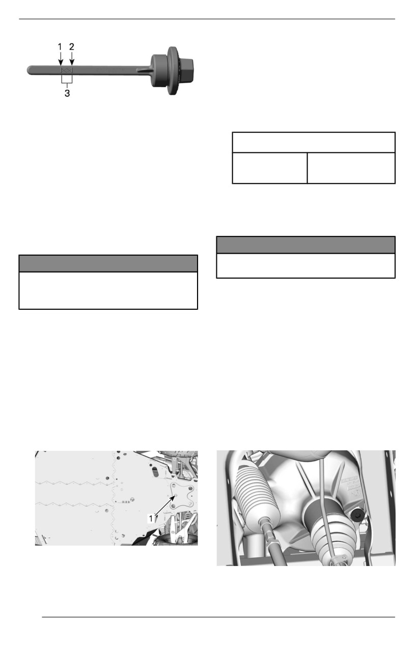
MAINTENANCE PROCEDURES
- Dipstick area.
4. Remove the dipstick.
5. Remove the drain plug.
6. Let oil completely drain from
gearbox.
7. Clean drain plug from any metallic
1. MIN.
particles.
2. MAX.
8. Install the drain plug.
3. Operating range
Tighteniing Torque
7. Add oil (if required):
20 ± 2 Nm
1. Place a funnel into the dipstick
Drain plug
(15 ± 1 lbf-ft)
hole.
2. Add a small amount of recom-
9. Refill gearbox.
mended oil.
3. Recheck oil level often.
NOTE: The oil should be level with
4. Repeat the above procedures
the bottom of the oil level orifice.
until oil level reaches the dip-
stick's upper mark.
NOTICE
Use ONLY the recommended type
NOTICE
of oiil.
Operatiing the gearbox wiith an iim-
proper oill level may severely dam-
10. Reinstall dipstick.
age gearbox.
11. Wipe off any spillage.
NOTE:
FRONT DIFFERENTIAL
Do not overfiilll. Wipe off any
spilllage.
Verifying the Front Diifferentiial Oiil
Level
8. Properly tighten oil dipstick.
1. Place the vehicle on a level
surface.
Changiing the Gearbox Oiil
2. Clean filler plug area prior to
1. Place the vehicle on a level
checking oil level.
surface.
2. Place a drain pan underneath the
The filler plug is located on the
oil drain plug area.
right side of the front differential.
1. Gearbox drain plug area
3. Clean the following areas.
VISCO-LOK
DIFFERENTIAL
(NO
– Drain plug area
ACTUATOR)
154
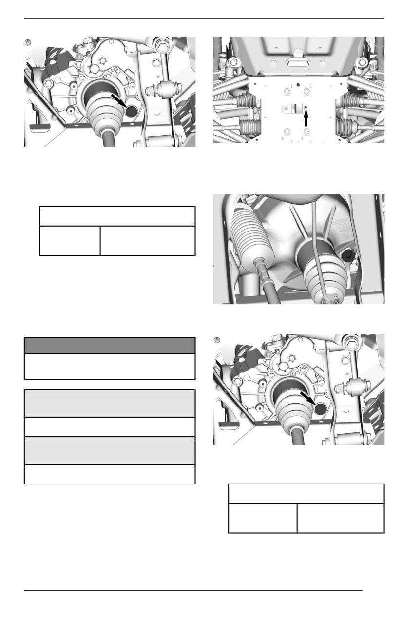
MAINTENANCE PROCEDURES
4. Place a drain pan under the rear
SMART-LOK
differential.
3. Remove the filler plug.
5. Remove drain plug.
4. Check oil level. The oil should
6. Unscrew filler plug.
reach the lower edge.
5. Reinstall the filler plug.
Tiightening Torque
16.5 ± 2.5 Nm
Filler plug
(146 ± 22 lbf-in)
Recommended Front Diifferentiial
Oill
The XPS oil is specially formulated to
meet the lubrication requirements of
VISCO-LOK
DIFFERENTIAL
(NO
this differential. BRP strongly recom-
ACTUATOR)
mends the use of its XPS oil.
NOTICE
Do not use another type of oil
when serviiciing.
XPS Recommended Front
Diifferentiial Oiil
75W90 Synthetic gear oil
Allternative if XPS Product iis not
SMART-LOK
Avaiilable
7. Let oil drip completely.
75W90 (API GL-5) synthetic gear oil
8. Install drain plug.
Tightening Torque
Changing the Front Diifferentiial Oiil
2.5 ± 0.5 Nm
1. Place vehicle on a level surface.
Drain plug
(24 ± 4 lbf-in)
2. Set gearbox in park position.
3. From underneath the vehicle,
9. Refill differential with recom-
clean the drain plug area.
mended
oil
for
optimal
performance.
155
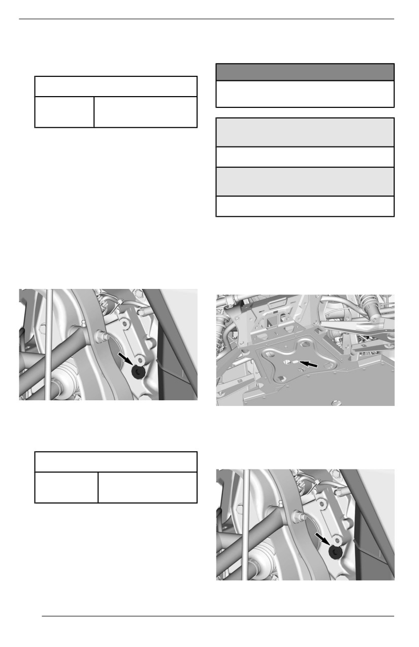
MAINTENANCE PROCEDURES
10. For the differential oil capacity, re-
this final drive unit. BRP strongly rec-
fer to Technical Specifications.
ommends the use of its XPS oil.
11. Reinstall filler plug.
NOTICE
Tighteniing Torque
Do not use another type of oiil
when serviiciing.
16.5 ± 2.5 Nm
Filler plug
(146 ± 22 lbf-in)
XPS Recommended Fiinall Drive
Oill
Rear Final Drive
75W90 Synthetic gear oil
Veriifyiing the Rear Fiinall Drive Oiil
Levell
Allternatiive if XPS Product is not
Avaiilable
1. Place the vehicle on a level
surface.
75W90 (API GL-5) synthetic gear oil
2. Remove the rear wheel on the
right side of the vehicle.
3. Clean filler plug area prior to
Changiing the Rear Fiinal Drive Oill
checking oil level.
1. Place vehicle on a level surface.
2. Set gearbox in park position.
The filler plug is located behind the
3. From underneath the vehicle,
voltage/regulator.
clean the drain plug area.
4. Remove the filler plug.
DRAIN PLUG ACCESS HOLE
5. Check oil level. The oil should
4. Place a drain pan under the rear fi-
reach the lower edge.
nal drive.
6. Reinstall the filler plug.
5. Remove drain plug.
6. Unscrew filler plug.
Tighteniing Torque
16.5 ± 2.5 Nm
Filler plug
(146 ± 22 lbf-in)
Recommended Rear Finall Driive Oiil
The XPS oil is specially formulated to
meet the lubrication requirements of
156
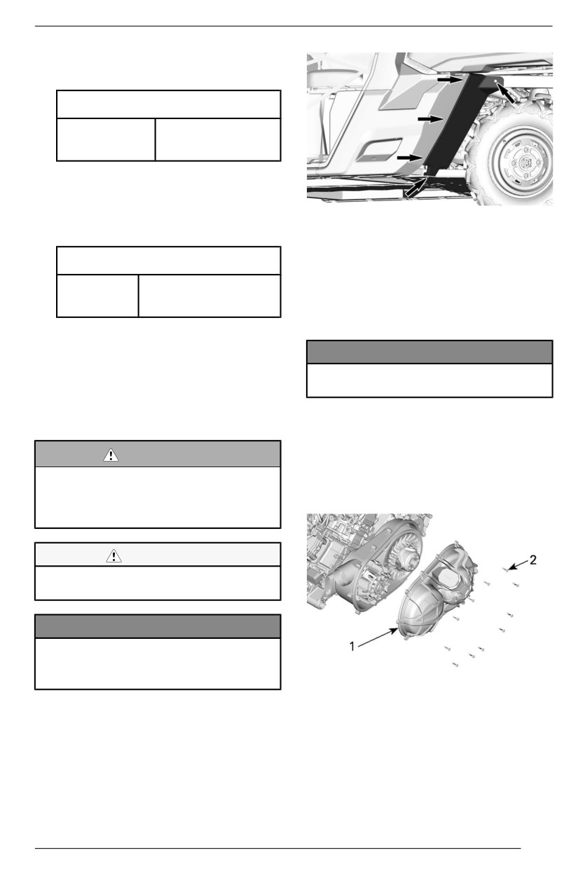
MAINTENANCE PROCEDURES
7. Let oil drip completely.
8. Install drain plug.
Tiightening Torque
2.5 ± 0.5 Nm
Drain plug
(24 ± 4 lbf-in)
9. Refill final drive with recommended
oil for optimal performance.
10. For the oil capacity, refer to Tech-
nical Specifications.
11. Reinstall filler plug.
Removiing the CVT Cover
1. Place the vehicle on a level
Tiightening Torque
surface.
2. If equipped, detach all CVT cooling
16.5 ± 2.5 Nm
Filler plug
ducts from the CVT cover.
(146 ± 22 lbf-in)
3. Manually, remove all CVT cover
retaining screws.
CVT COVER
NOTICE
For a better understanding, some il-
Do not use an iimpact tooll to re-
lustrations are taken with engine out
move CVT cover screws.
of vehicle. To perform the following in-
structions, it is not necessary to re-
move engine.
NOTE:
Remove the center top screw last to
support the cover during removal.
WARNING
Never touch CVT whille engine is
4. Remove the CVT cover and
its
runniing.
gasket.
Never drive vehiiclle when CVT
cover iis removed.
CAUTION
Engine must be cooll before cover
i
is removed.
NOTICE
Thiis CVT is lubrication free.
Never llubriicate any components
except driive pulley bearing.
1. CVT cover
2. CVT cover screws
Accessing the CVT Cover
Installling the CVT Cover
1. Tilt the cargo box.
2. Remove the LH rear deflector by
1. Install the center top screw of first.
removing the plastic rivets.
2. Tighten the CVT cover screws as
per following sequence.
157
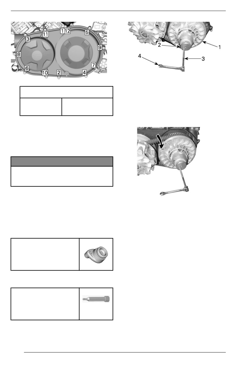
MAINTENANCE PROCEDURES
1. Fixed sheave of driven pulley
2. Adaptor
Tighteniing Torque
3. Puller/locking tool
4. Wrench
CVT cover
7 ± 0.8 Nm
5. To remove belt, slip the belt over
screws
(62 ± 7 lbf-in)
the top edge of fixed sheave, as
3. Reconnect all CVT cooling ducts.
shown.
Drive Belt
Removiing the Driive Belt (Twin
Cylinder Engine)
NOTICE
In case of a driive belt faillure, the
CVT, cover and air outlet must be
clleaned.
Please refer to Tips for Maximizing
Drive Belt Durability in Basic Proce-
dures for some important information.
Installliing the Driive Belt
For installation, reverse the removal
1. Remove the CVT Cover.
procedure. Pay attention to following
2. Install the adaptor in the threaded
details.
hole of the driven pulley.
The maximum drive belt life span is
obtained when the drive belt has the
Driven pullley adapter
proper rotation direction.
1. Install it so that the arrow printed
(P/N 708200720)
on belt is pointing towards front of
the vehicle, viewed from top.
3. Screw the puller/locking tool in the
threaded hole of the adaptor.
Pulller/locking tooll
(P/N 529000088)
4. Tighten to open the pulley.
158
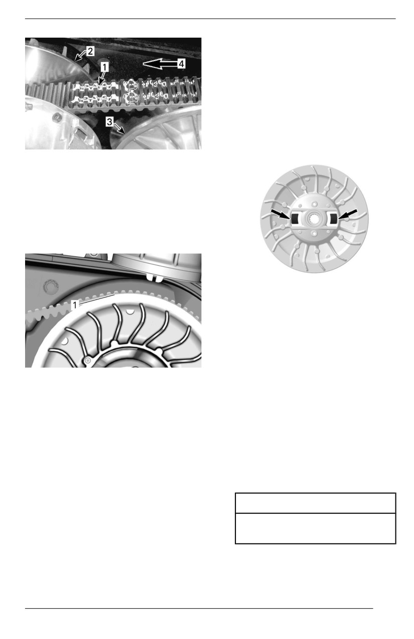
MAINTENANCE PROCEDURES
Driven Pullley
Inspect the bushings of the cam and
of the sliding sheave of the driven pul-
ley, replace worn parts.
V-Twiin onlly
Inspect rollers on fixed sheave.
Mono cyll. only
Inspect sliders on fixed sheave.
1. Arrow printed on belt
2. Drive pulley (front)
3. Driven pulley (rear)
4. Rotation direction
2. Turn the driven pulley until the low-
est portion of the cogs on the ex-
ternal surface of the drive belt is
even with the driven pulley edge.
Spark Plugs
Removiing the Spark Plug
1. Unplug spark plug cable.
2. Clean spark plug area with pres-
surized air before removing spark
plug.
1. Lowest portion of cogs even with driven pul-
3. Unscrew spark plug completely us-
ley edge
ing a spark plug socket, then re-
move it.
Drive and Driven Pulleys
Installling the Spark Pllugs
Inspecting Drive and Driven
1. Prior to installation make sure that
Pullleys
the contact surface of cylinder
head and spark plug is free of
This inspection must be performed by
grime.
an authorized Can-Am Off-road deal-
2. Using a feeler gauge, set the spark
er, repair shop, or person of your own
plug gap.
choosing for maintenance, repair, or
replacement.
Spark Pllug Gap
Driive Pullley
0.8 to 0.9 mm
Inspect the bushings and rollers of the
(.031 to .035 in)
sliding sheave of the drive pulley, re-
place worn parts.
3. Coat spark plug threads with the
following anti-seize lubricant.
159
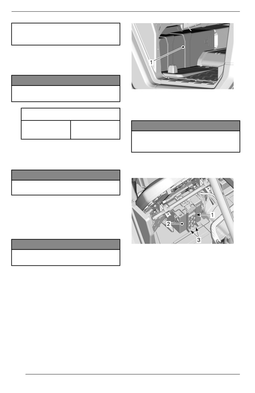
MAINTENANCE PROCEDURES
Copper-based antii-seiize
l
lubriicant
4. Screw spark plug into cylinder
heads by hand and tighten with a
torque wrench and a proper
socket.
NOTICE
Do not overtiighten spark plugs,
1. Battery cover
engine damage can occur.
3. Disconnect BLACK (-) cable first
Tighteniing Torque
then RED (+) cable.
11 Nm
NOTICE
Spark plug
(97 lbf-in)
Allways respect this order for dis-
assembly; disconnect BLACK (-)
cablle fiirst.
Battery
Battery Maiintenance
4.
Remove battery holder
retaining
screw(s).
NOTICE
Never charge a battery whiile iin-
stallled iin vehiclle.
These vehicles are equipped with a
VRLA battery (Valve Regulated Lead
Acid). It is a maintenance-free type
battery, there is no need to add water
to adjust electrolyte level.
NOTICE
1.
Battery holder
Never remove the battery sealing
2.
Battery
cap.
3.
Battery holder retaining screw(s)
5.
Remove battery holder.
Removiing the Battery
6.
Remove battery.
1. Remove under seat storage com-
partment if equipped.
2. Remove battery cover by unscrew-
ing the two 1/4 turn fasteners.
160
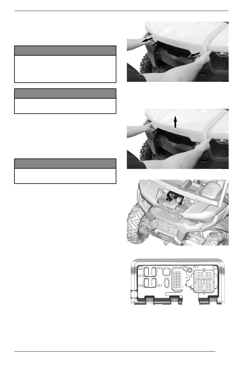
MAINTENANCE PROCEDURES
Installliing the Battery
Battery installation is the reverse of
the removal procedure.
NOTICE
Improper oriientatiion of the battery
cablles (reverse polariity) willl re-
sult in damage to the voltage
regullator.
PULLING ON FRONT
SERVICE
COVER
EDGE.
NOTICE
Allways connect RED (+) cable
Lift service cover.
first then BLACK (-) cable.
Fuses and Fusible Links
Fuse Replacement
If a fuse is burnt, replace it by one of
the same rating.
NOTICE
Do not use a higher rated fuse as
LIFTING FRONT SERVICE COVER EDGE.
this can cause severe damage.
Fuse Box Location
The vehicle is equipped with multiple
fuse boxes. Several are located inside
the front service center and another
one under the right passenger seat,
near the battery.
Two fuse links inside the electric har-
ness complete the system protection.
FUSE BOX SUPPORT
An additional 50A fuse to protect the
voltage regulator is located near the
battery.
To open front service cover, pull on
front edges of service cover to unlock
mechanism
FUSE BOX SUPPORT
Remove the battery cover to access
the rear secondary fuse box.
161
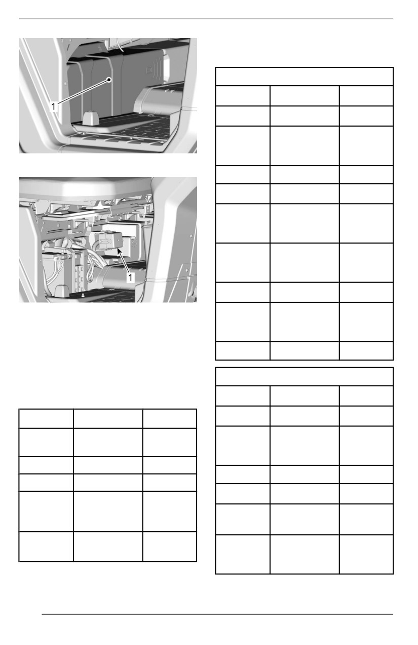
MAINTENANCE PROCEDURES
Master Fuse Box (PF1)– In-
side Front Service Center
CAB Models
No
Description
Rating
F11
Headlamps
20 A
DC1 (12V
F12
ACC outlet/
10 A
DC3
1.
Battery cover
F14
USB outlet
10 A
F16
Tail lamps
10 A
DC5/
F18
Power-tilt
20 A
bed
Accessory/
R3
12V ACC
—
outlet
R8
Brake lights
—
1.
Rear secondary fuse box
Accessory
R9
post 12V/
—
Fuse Box Descriiptiion
USB outlet
Fuses – Inside Front Service
R10
A/C clutch
—
Center
Inside the front storage center, the
Alll Other Modells
fuse box number is molded in the
support.
No
Description
Rating
F11
Headlamps
20 A
No
Description
Rating
Master fuse
DC1 (12V
PF1
—
box
F12
ACC outlet/
10 A
DC3
PF3
DPS
40 A
F14
USB outlet
10 A
PF4
Accessories
30 A
F16
Tail lamps
10 A
Air
PF5
Conditioning
—
Heater (if
(if equipped)
F17
5A
equipped)
Smart-Loc (if
PF7
20 A
DC5/
equipped)
F18
Power-tilt
20 A
bed
162

MAINTENANCE PROCEDURES
Alll Other Modells
Secondary Fuse Box
(Under passenger seat)
No
Description
Rating
Descrip
No
Rating
Accessory/
tiion
R3
12V ACC
—
outlet
Cooling
R1
—
fan
R8
Brake lights
—
R2
Main
—
Accessory
R9
post 12V/
—
HVAC Fuse Box (PF5)– In-
USB outlet
side Front Service Center
Secondary Fuse Box (PF2)–
No
Descriiptiion
Ratiing
Under passenger seat
Fan speed
F1
20 A
Secondary Fuse Box
relays
(Under passenger seat)
Air
Descriip
F3
conditioning
5A
No
Ratiing
tion
relay
Cluster/
Fan speed
F4
10 A
RLS
—
relays
relay — Low
Ignition/
Fan speed
RMS
relay —
—
F5
injection/
10 A
fuel pump
Medium
Engine
Fan speed
relay —
—
Control
RHS
F6
10 A
High
Module
(ECM)
Fuse Links
Wheel
F7
drive
10 A
Descrip
Fuse link
Rating
actuator
tion
Ignition
1
Main
18 awg
F8
switch
10 A
Clock
Accessory
2
14 awg
post
Cooling
F9
25 A
fan
Regulator Fuse
Oxygen
sensor
F18
10 A
Descrip
No
Rating
Emission
tion
control
—
Regulator
50 A
Rear
F28
10 A
outlet
163
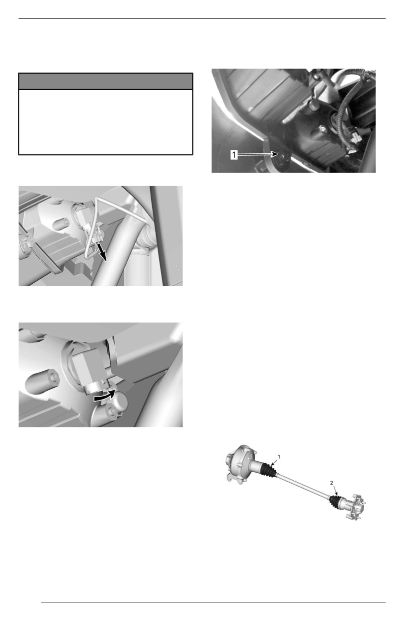
MAINTENANCE PROCEDURES
LIGHTS
NOTE:
Adjust headlights evenly.
Headllight Bulb Repllacement
NOTICE
Never touch gllass portiion of a hall-
ogen bullb wiith bare fingers, it
shortens its operating liife. If gllass
i
is touched, clean it wiith isopropyl
allcohol which will not lleave a fillm
on the bullb.
Unplug connector from bulb.
1. Adjustment screw
Taillliight Bullbs Repllacement
The taillights are built with LEDs (light
emitting diode) and this technology
proved to be reliable. In the unlikely
event they do not work, have them
checked by an authorized Can-Am
dealer, a repair shop or person of your
choosing.
TYPICAL
Drive Shaft Bellow and
Rotate bulb.
Protector
Inspecting Drive Shaft Belllows and
Protector
1. Visually inspect drive shaft protec-
tors and bellows condition.
2. Check protectors for damage or
rubbing against shafts.
3. Check bellows for cracks, tears,
leaking grease, etc.
4. Repair or replace damaged parts
as necessary.
TYPICAL
Pull out bulb.
Properly reinstall removed parts in the
reverse order of their removal.
Validate headlights operation.
Headllight Beam Aiiming
Turn adjustment screw to adjust beam
1. Drive shaft bellow - differential side
height to your convenience.
2. Drive shaft bellow - wheel side
164
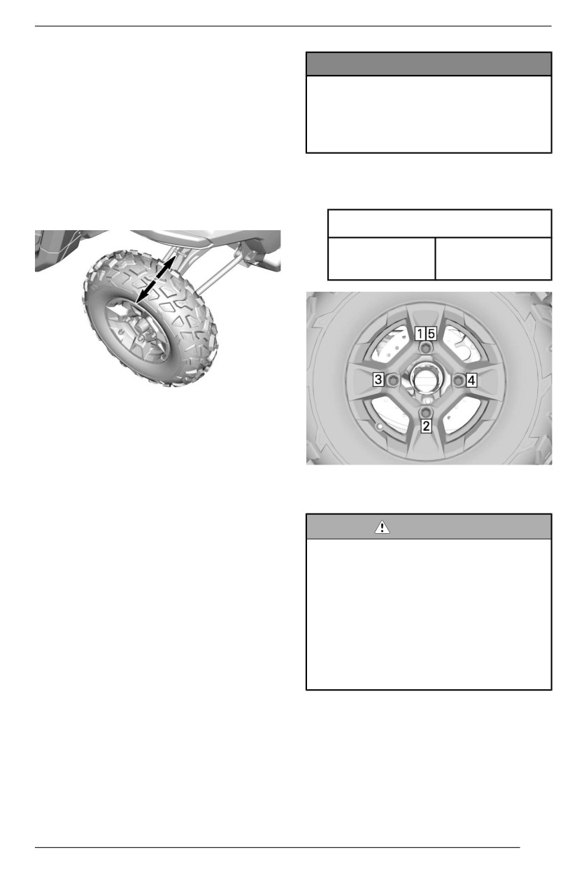
MAINTENANCE PROCEDURES
Wheel Bearing
NOTICE
Inspecting a Wheell Bearing
Always use the recommended
wheell lug nuts for the type of
1. Lift and support vehicle. Refer to
wheell. Usiing a different lug nut
Lifting and Supporting the Vehicle.
could cause damages to the rim
2. Push and pull the wheels from the
or studs.
upper edge to feel the play.
3. See an authorized Can-Am Off--
4. Tighten wheel lug nuts in accord-
road dealer, a repair shop or a per-
ance with the following illustration.
son of your choosing if there is
excessive play.
Tightening Torque
Wheel lug
100 ± 10 Nm
nuts
(74 ± 7 lbf-ft)
TYPICAL
Wheels and Tires
Removing a Wheel
TIGHTENING SEQUENCE
1. Place the vehicle on a level
surface.
Tiire Pressure
2. Place shift lever on PARK position.
3. Loosen the wheel lug nuts.
WARNING
4. Lift and support vehicle. Refer to
Tire pressure greatly affects ve-
Lifting and Supporting Vehicle
hiiclle handliing and stabiiliity.
section
Insufficient pressure may cause
5. Remove lug nuts and wheel.
tiire to defllate and rotate on wheell.
Overpressure may burst the tiire.
Installliing a Wheel
Always folllow recommended
1. Inspect studs threads and lug nuts.
pressure.
Replace if needed.
NEVER set tire pressure bellow
2. Install the wheel.
minimum. It could cause the tiire to
diisllodge from the riim.
NOTE: The tires are unidirectional
and their rotation must be kept in a
Check pressure when tires are colld
specific direction for proper operation.
before using the vehicle. Tire pressure
changes with temperature and alti-
3. Install all lug nuts by hand.
tude. Recheck pressure if one of
these conditions has changed.
165
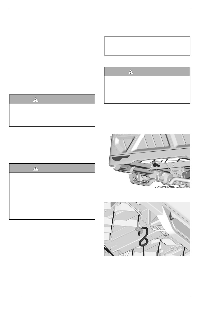
MAINTENANCE PROCEDURES
Refer to the Tires Pressure and Maxi-
4. Lubricate the upper spherical ball
mum Load Label on your vehicle for
joint of the power-tilt bed shock
applicable pressure.
and the lower joint.
NOTE:
Although the tires are specifically de-
XPS suspension synthetiic
signed for off-road use, a flat may still
grease
occur. Therefore, it is recommended
to carry a tire gauge, tire pump and a
Securiing the Long Cargo Box
repair kit.
WARNING
Tiire Inspection
When workiing on a vehiiclle
Check tire for damage and wear. Re-
equiipped with a long cargo box,
place if necessary.
always secure the cargo box wiith
a long box retaiiner tool before
WARNING
working under the cargo box.
Do not rotate tires. The front and
rear tires have a different size.
1.
If installed, remove the draw bar.
The lleft and right tiires have diiffer-
2.
Install one end of the clevis pin of
ent uniidirectiionall tread patterns.
the long box retainer tool into the
rear hole of the cargo box frame.
Tiire Replacement
Tire replacement should be performed
by an authorized Can-Am Off-road
dealer, a repair shop or a person of
your choosing.
WARNING
Replace tiires only with the same
type and size as oriigiinall tires.
For uniidiirectiionall tread pattern,
ensure that the tires are iinstallled
3.
Install a S-hook into the clevis pin
i
in the correct directiion of rotatiion.
hole.
Tires should be repllaced, by an
experienced person, in accord-
ance wiith tiire iindustry standards
and toolls.
Power-tilt Bed
Lubricatiing the Power-tiilt Bed
1. Lift the cargo box.
2. Support the cargo box securely by
using the procedure in Securing
4.
Repeat previous steps on the oth-
the Long Cargo Box
er side of the cargo box.
3. Detach the power-tilt bed shock
5.
With the help of another person,
from the vehicle.
raise the cargo box.
166
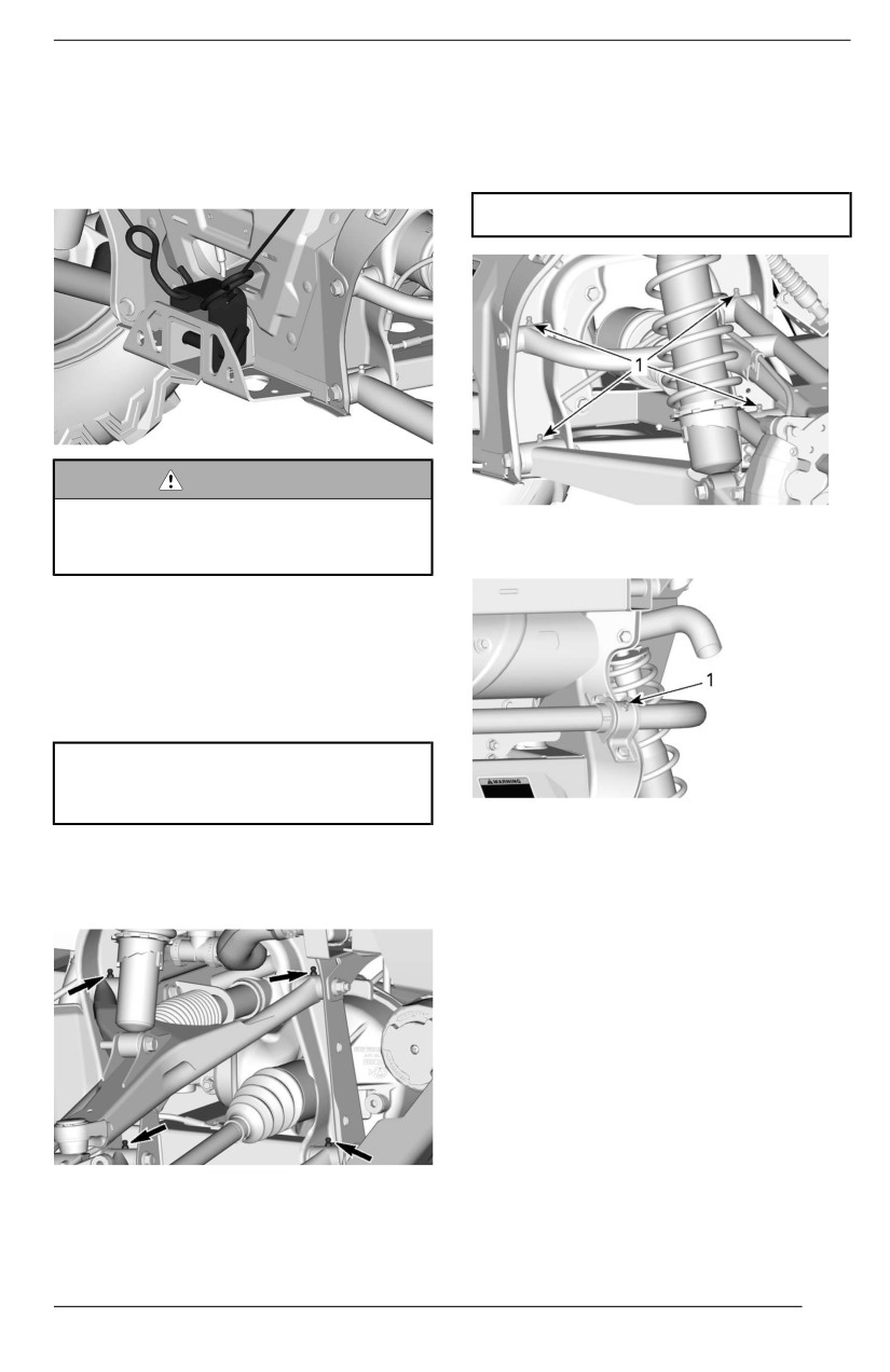
MAINTENANCE PROCEDURES
6. While your helper hold the cargo
Lubricatiing the Rear Suspension
box in this position, install the
Lubricate rear suspension arms (two
U-bracket of the tool over the ve-
grease fittings on each arm) and rear
hicle hitch receiver and lock it in
stabilizer bar bushing.
place using the provided lock pin.
XPS synthetic suspension grease
WARNING
To avoiid severe injury, never try
TYPICAL
to raiise, hold, and secure the car-
1. Rear suspension arm grease fittings
go box when you are alone.
Suspensions
Lubriicating the Front Suspension
1. Lubricate front arms and stabilizer
bar bushings (if equipped).
XPS synthetiic suspension
grease
TYPICAL
1. Rear stabilizer bar bushing grease fitting
There are two grease fittings on
each suspension arm oriented
Suspension Inspectiion
upwards.
See an authorized Can-Am Off-road
dealer, a repair shop or person of your
choosing if any problem is detected.
Shock Absorbers
Inspect shock absorber for leaks,
bump stop wear out or other dam-
ages. Verify fasteners are still well
tightened.
Front Suspension Arms
Check suspension arms for cracks,
bending or other signs of excessive
wear or damage.
167
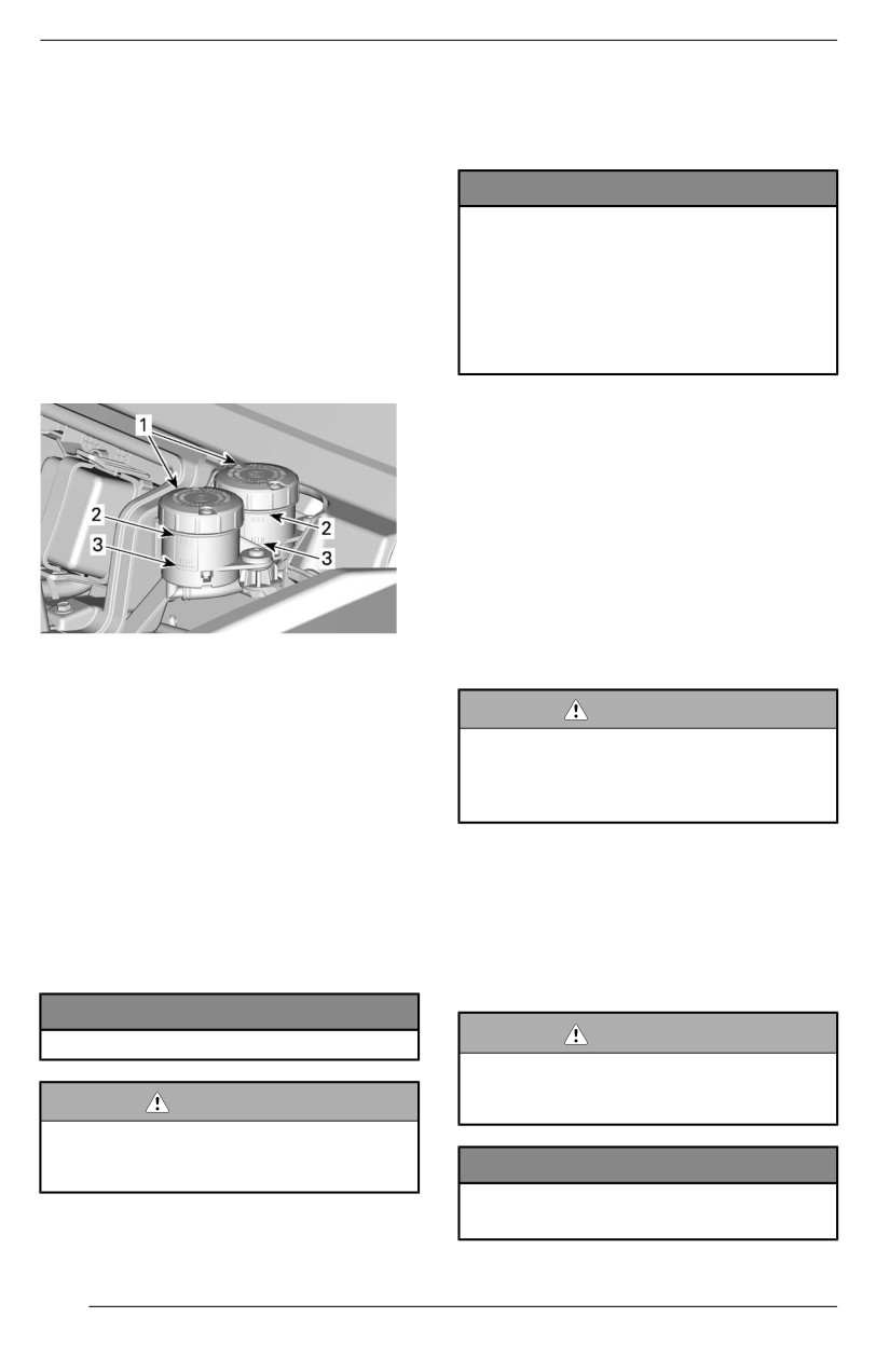
MAINTENANCE PROCEDURES
Rear Suspensiion Arms
Recommended Brake Fluid
Check suspension arms for cracks,
Always use brake fluid meeting the
bending or other signs of excessive
specification DOT 4 only.
wear or damage.
NOTICE
Brakes
To avoiid seriious damage to the
brakiing system, do not use fluiids
Brake Flluiid Reservoiir Level
other than the recommended one,
Veriificatiion
nor mix different fluids for topping
With vehicle on a level surface, check
up.
brake fluid in reservoir for proper level.
Do not use brake fluiid taken from
Brake fluid level should be between
old or already opened containers.
MIN. and MAX. marks.
Inspecting Brake System
The brake inspection, maintenance
and repair should be performed by an
authorized Can-Am dealer, a repair
shop or person of your choosing.
However, verify the following between
visits to your dealer:
- Brake fluid level
- Brake system for fluid leaks
1. Brake fluid reservoirs
- Brake pad wear
2. MAX
- Brake cleanliness
3. MIN
WARNING
The brake fluid replacement or
NOTE:
brake system maintenance and
A low level may indicate leaks or worn
repaiirs should be performed by an
brake pads.
authorized Can-Am dealer.
Addiing Brake Flluiid
SEAT BELTS
1. Clean both reservoir covers and
the surrounding area.
Clleaniing Seat Bellt
2. Add enough new brake fluid to in-
To clean dirt and debris from the seat
crease the level near the MAX
belts, sponge the straps with mild
mark.
soap and water.
NOTICE
WARNING
Do not overfiilll.
To avoiid damaging the seat bellt
components, never use a pres-
WARNING
sure washer to cllean them.
Ensure diaphragm is pushed back
i
insiide the cover before installiing
NOTICE
i
it.
Do not use bleach, dye, or house-
holld detergents.
168
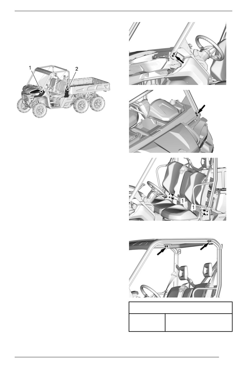
MAINTENANCE PROCEDURES
Cage
Cage Fasteners
Remove trim to get access to the
fasteners.
1. Front fender
2. Side cage cover
Tighten cage fasteners to specifica-
tion periodically.
1. Lower cage fasteners
Tiightening Torque
Cage
67.5 ± 2.5 Nm
fasteners
(50 ± 2 lbf-ft)
169
VEHICLE CARE
Vehicle Cleaning and
fresh water is necessary to preserve
vehicle and its components after each
Protection
operating day.
NOTICE
Metallic parts lubrication is highly
Never use a hiigh pressure washer
recommended.
to clean the vehiicle. USE LOW
PRESSURE ONLY (liike a garden
Use anti-corrosive lubricant or an
hose).
equivalent.
Hiigh pressure can cause damage
to electrical or mechanical
XPS Lubricant and anti-corrosive
components.
Painted parts which are damaged
Pay attention to certain areas where
should be properly repainted to pre-
salt-water, mud or debris can accumu-
vent rust.
late and potentially cause:
When required, wash the body with
- Fire
warm water and soap (only use mild
- Wear
detergent). Apply non-abrasive wax.
- Interference
- Corrosion.
NOTICE
This list includes but is not limited to:
Never clean pllastic parts with
- Around exhaust system and be-
strong detergent, degreasiing
tween muffler and muffler cover
agent, paiint thinner, acetone, etc.
- Under and around the fuel tank
- Radiator
Protect the vehicle with a cover to pre-
- Shock absorbers
vent dust accumulation during
- Around front and rear differentials
storage.
- Around and underneath engine
and gearbox
NOTICE
- Inside wheels
- On top of skid plates.
The vehiclle has to be stored in a
cooll and dry place and covered
with an opaque tarpaullin. This wiilll
WARNING
prevent sun rays and griime from
Debris accumulation coulld lead to
affectiing pllastic components and
a vehicle fire when the exhaust
vehiiclle fiinish.
system iis hot and the debriis are
driied.
In some cases, that coulld result iin
serious properlly damages, injju-
ries or even death.
Cllean often and regularlly the area
surroundiing the exhaust system
when riding iin swamp, bog, hay or
dead leaves.
In other situatiions, clean as per
maiintenance schedule
requirement.
When vehicle is used in salt-water en-
vironment rinsing the vehicle with
170
STORAGE AND PRESEASON PREPARATION
When a vehicle is not in use for more than 4 months, proper storage is a
necessity.
If the vehicle is to be remain inactive for more than 21 days, disconnect the
BLACK (-) cable of the battery.
The use of a low amperage trickle charger is recommended to keep battery fully
charged.
Before using your vehicle after storage, a preparation is required.
See an authorized Can-Am Off-road dealer, a repair shop, or a person of your
own choosing to have your vehicle prepared properly.
171
STORAGE AND PRESEASON PREPARATION
This page is intentionally blank
172
TECHNICAL INFORMATION
173
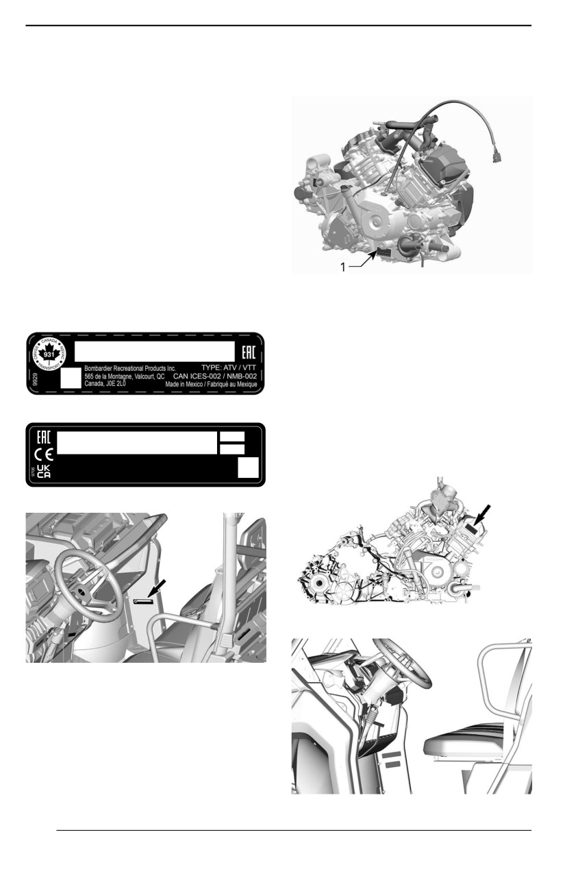
VEHICLE IDENTIFICATION
The main components of your vehicle
Engine Identification Number
(engine and frame) are identified by
(EIN)
different serial numbers. It may some-
times become necessary to locate
these numbers for warranty purposes
or to trace your vehicle in the event of
loss. These numbers are required by
the authorized Can-Am Off-road deal-
er to complete warranty claims prop-
erly. We strongly recommend that you
take note of all the serial numbers on
your vehicle and supply them to your
insurance company.
Vehicle Identification Number
The VIN decal is located inside the
TYPICAL
cockpit, on the right wall under the
1. EIN (Engine Identification Number)
glove box.
Compliance Label
Regulation (EU) 2016/1628
Applicable for Non-Road Mobille
Machineriies
VIN LABEL - EUROPEAN COUNTRIES
Vehicles who comply to Regulation
(EU) 2016/1628 (NRMM) are identi-
kW
fied on the engine valve cover as well
kg
as on the vehicle, near the VIN label.
Bombardier Recreational Products Inc.
TYPE: SbS Made in Mexico
565 de la Montagne, Valcourt, QC
BRP-Rotax GmbH Co. KG
Canada, J0E 2L0
Rotaxstrasse 1
Gunskirchen, A-4623, Austria
VIN LABEL - OTHER COUNTRIES
TYPICAL
TYPICAL - VIN LABEL LOCATION
174
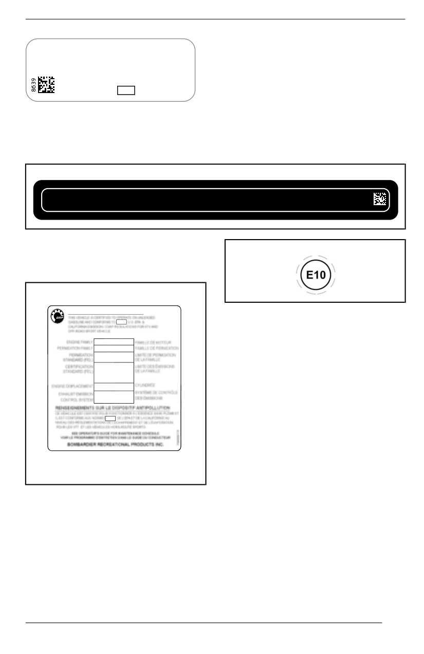
VEHICLE IDENTIFICATION
NOTE:
Rotax
NRSC G1 CO2 g/kWh:
XXXX
Tampering with the engine or its com-
#
MXXXXXXX
ponents voids the EU type-approval of
Production date:
MM-YYYY
Family type:
that particular engine.
XXXXXX
e13
AT1/P V-####
TYPICAL - NRMM IDENTIFICATION LABEL
ROHVA Compliiance Labell
This label is located inside the cockpit, on the longitudinal cage tube, above the
driver seat.
BRP Certi es that this ROV complies with the American National Standard for
This roll over protective structure meets the performance requirements of ISO 3471:
Recreational O-Highway Vehicles, ANSI / ROHVA 1 - 2016 Standard.
2008 and OSHA requirements of 29 CFR § 1928.53 (Tested at GVWR).
BRP certi e que ce véhicule récréatif hors-route est conforme à la norme ‘’ American
Cette structure de protection contre le retournement respecte les requis de
National Standard for Recreational O-Highway Vehicles’’, ANSI / ROHVA 1 - 2016.
performance de la norme ISO 3471: 2008 et de OSHA 29 CFR § 1928.53 (Testé au
PNBV).
704906981
Emiissiion Control Informatiion
This label is located inside the cockpit,
on the LH panel under the dash.
EMISSION CONTROL INFORMATION
WHEN APPLICABLE
Ethanol Compliiance Piictogram
This label is always located near the
fuel cap.
175
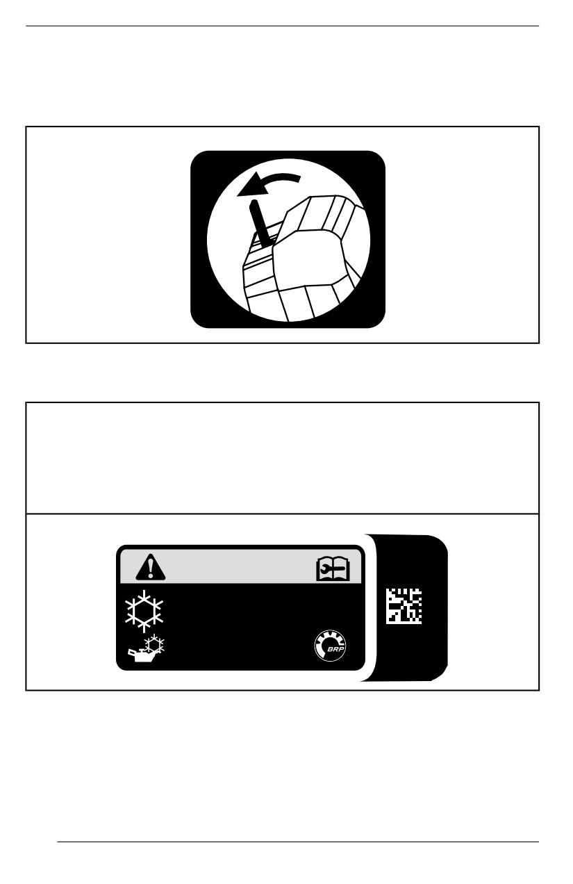
VEHICLE IDENTIFICATION
Technical Information Label
Miiddlle Seat Opening Piictogram
This pictogram is located near the locking tab of the middle seat.
HVAC Information Labell
This decal is located on the inner side of the front service cover.
READ THE REPAIR MANUAL BEFORE SERVICING
Type of refrigerant: R-134A
Refrigerant filling capacity: 520 g (18 oz)
Oil type: PAG
Safety Standards for Motor Vehicle Refrigerant Vapor Compressions Systems:
SAE J639
R-134a
520 g (18 oz)
8394
PAG
SAE J639
176
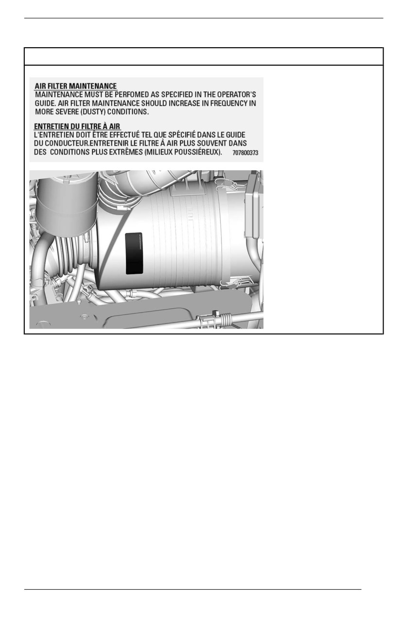
VEHICLE IDENTIFICATION
Aiir Fillter Maiintenance Labell
North American Models
177
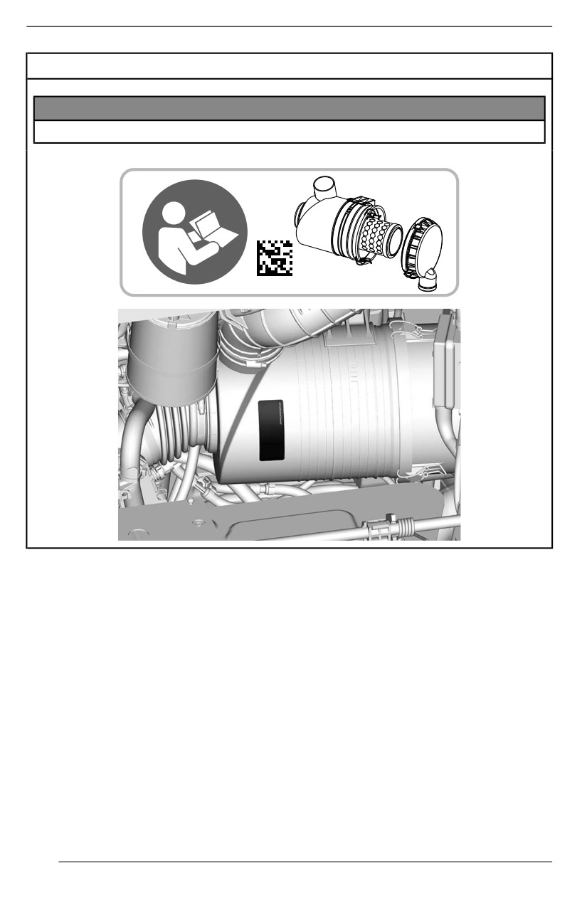
VEHICLE IDENTIFICATION
Models Outside North America
NOTICE
To repllace the aiir fillter, refer to the operator’s guide for the procedure.
7686
178
NOISE EMISSION CONTROL SYSTEM
REGULATION
USA and Canada Only
Tampering wiith Noise Control System Is Prohibiited!
U.S. Federal law and Canadian provincial laws may prohibit the following acts or
the causing there of:
1. The removal or rendering inoperative by any person other than for purposes
of maintenance, repair or replacement of any device or element of design in-
corporated into any new vehicle for the purpose of noise control prior to its
sale or delivery to the ultimate purchaser or while it is in use or
2. The use of the vehicle after such device or element of design has been re-
moved or rendered inoperative by any person.
Among those Acts Presumed to Constiitute Tampering Are the Acts Listed
Below:
1. Removal or alteration or the puncturing of the muffler or any engine compo-
nent which conducts removal of engine exhaust gases.
2. Removal or alteration or the puncturing of any part of the intake system.
3. Replacing any moving parts of the vehicle or parts of the exhaust or intake
system, with parts other than those specified by the manufacturer.
4. Lack of proper maintenance.
179

NOISE EMISSION AND VIBRATION VALUES
(MACHINERY DIRECTIVE 2006/42/EC
COMPLIANCE MODELS)
Noise emission and vibration values are measured in accordance with
Machinery Directive 2006/42/EC on a paved surface, at neutral or without belt.
ENGINE
HD10
Sound Pressure Level (LpA)
82 dB (A) (Uncertainty (KpA) 3dB)
Noise
Sound Power Level (LwA)
96 dB (A) (Uncertainty (KwA) 3dB)
Hand-arm system
Less than 2.5 m/s2
Vibration
Whole body at seat
Less than 0.5 m/s2
180
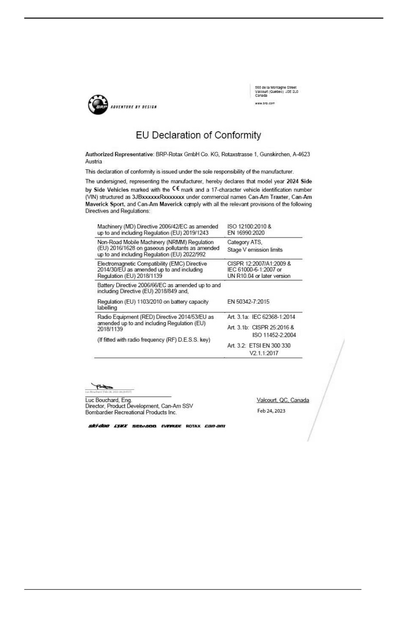
DECLARATION OF CONFORMITY
EU Declaration of Conformity
181
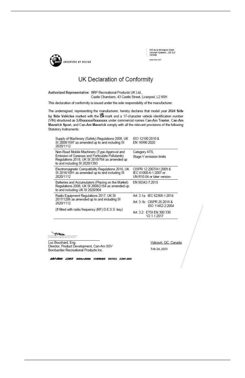
DECLARATION OF CONFORMITY
UK Declaration of Conformity
182
EAC DECLARATION OF CONFORMITY
Left blank for Eurasian Conformity
mark where applicable
183
EAC DECLARATION OF CONFORMITY
This page is intentionally blank
184
TECHNICAL
SPECIFICATIONS
185
TECHNICAL SPECIFICATIONS
Engine
ROTAX Twin cylinder.
4-stroke, Single Over
Engine type
Head Camshaft
(SOHC), liquid cooled
Number of cylinders
2
8 valves (mechanical
Number of valves
adjustment)
0.08 to 0.12 mm
Intake valve clearance
(.0031 to .0047 in)
0.13 to 0.17 mm
Exhaust valve clearance
(.0051 to .0067 in)
91 mm
Bore
(3.58 in)
75 mm
Stroke
(2.95 in)
976 cm³
Displacement
(59.56 in³)
Spark arrestor approved
Exhaust system
by USDA Forest Service
with a Catalyst
Air filter
Synthetic paper filter
Lubrication System
Type
Wet sump
Replaceable cartridge oil
Oil filter
filter (paper type)
2l
Capacity
(2.1 qt (liq.,US))
General
5W40 Synthetic blend oil
purpose
Engine oil
Cold
Recom
tempera
0W40 Synthetic oil
mended
ture
XPS oil
Warm
tempera
10W50 Synthetic oil
ture
186
TECHNICAL SPECIFICATIONS
Lubrication System
Use a 5W40 or 10W50
Alternate oil if XPS
motor oil that meets the
products are not
requirements for API
available
service classification SN
or JASO MA2
Cooling System
Recommended XPS
Extended life pre-mixed
coolant
coolant
Ethyl glycol / water mix
(50%/50%).
Alternate if XPS product
Coolant
or coolant specifically
is not available
designed for aluminum
engines
6l
Capacity
(1.59 gal (liq.,US))
Transmission
CVT (Continuously
Type
Variable Transmission)
Engagement
2000 ± 100 RPM
Gearbox
Dual range (HI-LO) with
Type
PARK, neutral and
reverse
1.5 l
Capacity
(1.396 gal (liq.,US))
Recommended XPS
XPS 75W140 Synthetic
Gearbox oil
gearbox oil
gear oil
Alternate if XPS product
75W 140 API GL-5
is not available
Electrical System
HVAC
850 W @ 5000 RPM
models
Magneto generator output
All other
650 W @ 5000 RPM
models
187
TECHNICAL SPECIFICATIONS
Electrical System
IDI (Inductive Discharge
Ignition system type
Ignition)
Quantity
2
Make and type
NGK LMAR8C-9
Spark plug
0.8 to 0.9 mm
Gap
(.031 to .035 in)
Maintenance free - SLA
Type
(Sealed Lead Acid)
Voltage
12 volts
Battery
Nominal rating
30 A•h
Power starter output
750 W
Headlight
4 x 35W (H8)
Taillight
LED
Signature lights
Limited
LED
Refer to Fuses in the
Fuses
Maintenance section
Fuel System
Electronic fuel injection
Fuel delivery
(EFI) with iTC
Throttle body
54 mm with ETA
Fuel pump
Electric (in fuel tank)
1350 ± 100 RPM
Idle speed
(1500 ± 100 RPM when
HVAC is ON)
Type
Regular unleaded
gasoline
North
87 AKI (R+M)/2
Fuel
America
Minimum
Octane
Outside
rating
North
91 RON
America
188
TECHNICAL SPECIFICATIONS
Fuel System
± 38 l
Fuel tank capacity
(10 gal (liq.,US))
± 8.5 l
Fuel remaining when low fuel light turns ON
(2.2 gal (liq.,US))
Front Drive
Limited
Spiral bevel gear
Smart-Lok electronic
control locking front
differential
Type
Selectable 4WD / 6WD
Other
with Visco-Lok
models
auto-locking front
differential, spiral gears
Front drive ratio
3.6:1
350 ml
Limited
(23.7 fl oz(US))
Capacity
Other
400 ml
models
(14 fl oz (US))
Front differential oil
XPS 75W90 Synthetic
Recommended XPS oil
gear oil
Alternate if XPS product
75W 90 API GL-5
is not available
CV joint grease
XPS CV joint grease
Spline's propeller shaft grease (grease applied to
XPS Propeller shaft
spline connections)
grease or equivalent
Middle and Rear Final Drive
Type
Angle drive (spool gear)
Middle drive ratio
3.43:1
Rear final drive ratio
3.6:1
575 ml
Capacity
(19.5 fl oz (US))
Rear final drive oil
XPS 75W90 Synthetic
Recommended XPS oil
gear oil
189
TECHNICAL SPECIFICATIONS
Middle and Rear Final Drive
Alternate if XPS product
75W 90 API GL-5
is not available
Steering
Type
Rack and pinion
Steering wheel
Adjustable tilt steering
Front Suspension
Arched double
Limited
suspension arms with
stabilizer bar
Suspension type
All other
Arched double
models
suspension arms
279 mm
Limited
(11 in)
Suspension travel
All other
305 mm
models
(12 in)
Quantity
2
Shock absorber
Type
Gas charged
Preload adjustment
5 positions cam
Rear Suspension
Arched TTA with
Suspension type
stabilizer bar
279 mm
Limited
(11 in)
Suspension travel
All other
305 mm
models
(12 in)
Quantity
2
Shock absorber
Type
Gas charged
Preload adjustment
5 positions cam
190
TECHNICAL SPECIFICATIONS
Brakes
Qty
2
220 mm (8.7 in)
Front brake
ventilated brake disc
Type
with hydraulic
twin-pistons calipers
Qty
2
220 mm (8.7 in)
Rear brake
ventilated brake disc
Type
with hydraulic
twin-pistons caliper
Type
DOT 4
Brake fluid
Approximately 310 ml
Capacity
(10.5 fl oz (US))
Caliper
Floating
Brake pad material
Metallic
0.5 mm
Minimum brake pad thickness
(.02 in)
4 mm
Minimum brake disc thickness
(.157 in)
0.2 mm
Maximum brake disc warpage
(.01 in)
Tires
Recommended tire
inflation pressure is
found on the Tire Label.
Pressure
Refer to appropriate
Important On-Product
Labels section for its
location.
762 x 229 x 356 mm
Limited
30 x 9R14 in)
Front
All other
686 x 229 x 356 mm
Tire size
models
(27 x 9R14 in)
762 x 254 x 356 mm
Rear
Limited
(30 x 10R14 in)
191
TECHNICAL SPECIFICATIONS
Tires
All other
686 x 279 x 356 mm
models
(27 x 11R14 in)
3 mm
Minimum tire thread depth
(.118 in)
Wheels
Type
Cast aluminum
35.6 x 18 cm
Front
(14 x 7 in)
35.6 x 18 cm
Rim size
Limited
(14 x 7 in)
Rear
All other
35.6 x 20.3 cm
models
(14 x 8.5 in)
100 ± 10 Nm
Wheel lug nuts torque
(74 ± 7 lbf-ft)
41.2 mm
Front
(1.6 in)
41.2 mm
Wheel Offset
Limited
(1.6 in)
Rear
All other
51 mm
models
(2 in)
Chassis
Profiled tube section,
Cage type
high strength steel, ISO
3471 certified
Dimensions
391.5 cm
DPS
(154 in)
Overall length
All other
405.7 cm
models
(159.7 in)
165.1 cm
Limited
(65 in)
Overall width
All other
162.5 cm
models
(64 in)
192
TECHNICAL SPECIFICATIONS
Dimensions
198 cm
DPS
(78 in)
203.3 cm
Overall height
XT
(80 in)
228.7 cm
Limited
(81 in)
294 cm
Wheelbase
(115.5 in)
137 cm
Front
(54 in)
Wheel track
130.4 cm
Rear
(51 in)
35.6 cm
Limited
(14 in)
Ground clearance
All other
33 cm
models
(13 in)
Loading Capacity and Weight
886 kg
DPS
(1,953 lb)
1 104 kg
Dry weight
Limited
(2,434 lb)
942 kg
XT
(2,077 lb)
Weight distribution (front/rear)
37/63
454 kg
Cargo box capacity
(1,000 lb)
113 kg
Tailgate capacity
(250 lb)
771 kg
DPS
(1,700 lb)
Total vehicle payload allowed
(including driver, passengers, all
545 kg
Limited
other loads and added accessories)
(1,200 lb)
XT
712 kg
193

TECHNICAL SPECIFICATIONS
Loading Capacity and Weight
(1,570 lb)
1688 kg
XT
(3721 lb)
Gross vehicle weight rating
All other
1 699 kg
models
(3,746 lb)
1 361 kg
Towing capacity
(3,000 lb)
136 kg
Tongue capacity
(300 lb)
50.8 x 50.8 mm
Receiver hitch
(2 x 2 in)
194
TROUBLESHOOTING
195
TROUBLESHOOTING GUIDELINES
CVT Belt Is Slipping
1. Water has entered in the CVT.
- Refer to Special Procedures.
“–” Is Displayed On the Gearbox Position Display
1. Shift lever is between 2 positions.
- Properly position the shift lever in the desired position.
2. Shift lever is not properly adjusted.
- Contact an authorized Can-Am Off-road dealer.
3. Electrical communication error.
- Contact an authorized Can-Am Off-road dealer.
Engine Does Not Turn
1. Starting procedure not performed correctly.
- Refer to Starting the Engine.
2. Shift lever is not set on PARK.
- Set shift lever to either in PARK or press the brake pedal.
3. Burnt fuse.
- Check fuses.
4. Weak battery or loose connections.
- Check charging system fuse.
- Check fault message in cluster.
- Check battery connections and terminals condition.
- Have the battery checked by an authorized Can-Am Off-road dealer.
5. Defective starter solenoid.
- Contact an authorized Can-Am Off-road dealer.
Engine Turns Over But Fails To Start
1. Flooded engine
- Active the drowned mode to start the engine. Refer to Flooded Engine in Spe-
cial Procedures section.
2. No fuel to the engine (spark plug dry when removed).
- Check fuel tank level.
- Check fuel pump fuse.
- Obstructed fuel pump pre-filter or fuel pump failure.
196
TROUBLESHOOTING GUIDELINES
See an authorized Can-Am Off-road dealer, a repair shop, or a person of your
own choosing for maintenance, repair, or replacement.
Please refer to the US EPA Emission-Related Warranty contained herein for
information about warranty claims.
3. Spark plug/ignition (no spark).
- Check ignition fuse.
- Remove spark plug then reconnect to ignition coil.
- Start engine with spark plug grounded to the engine away from spark plug
hole. If no spark appears, replace spark plug.
If trouble persists, see an authorized Can-Am Off-road dealer, a repair shop,
or a person of your own choosing for maintenance, repair, or replacement.
Please refer to the US EPA Emission-Related Warranty contained herein for
information about warranty claims.
Engine Lacks Acceleration or Power
1. Seat belt not buckled properly. Check cluster message.
-
Buckle up seat belt.
2. Fouled or damaged spark plug.
-
Replace spark plugs.
3. Engine air filter plugged or dirty.
-
Check air filter and replace if necessary.
–
Check deposits in engine air filter housing.
4. Water in CVT
-
Drain water from CVT. Refer to Special Procedures section.
5. CVT dirty or worn-out.
-
Contact an authorized Can-Am Off-road dealer.
6. Lack of fuel
-
Dirty or clogged fuel pump pre-filter. See an authorized Can-Am Off-road
dealer, a repair shop, or a person of your own choosing for maintenance, re-
pair, or replacement. Please refer to the US EPA Emission-Related Warranty
contained herein for information about warranty claims.
7. Engine is in Torque Limitation mode (if equipped).
-
Engine torque is gradually limited for protection when coolant temperature is
too high. Check multifunction gauge display for engine temperature.
-
Let engine cool down.
8. Engine is in limp home mode.
197
TROUBLESHOOTING GUIDELINES
- Multifunction gauge CHECK ENGINE indicator lamp is on and display shows
LIMP HOME. See an authorized Can-Am Off-road dealer, a repair shop, or a
person of your own choosing for maintenance, repair, or replacement. Please
refer to the US EPA Emission-Related Warranty contained herein for informa-
tion about warranty claims.
Engine Overheats
1. Low coolant level in cooling system.
- Check coolant level and refill. See Maintenance Procedures. Seek service
from an authorized Can-Am Off-road dealer, a repair shop, or a person of
your own choosing for maintenance, repair, or replacement. Please refer to
the US EPA Emission-related warranty contained herein for information about
warranty claims.
2. Cooling fan is not working.
- Ensure cooling fan is not jammed and working properly.
- Check fan fuse. See Fuses and Fusible Links in the Maintenance
Procedures.
3. Dirty radiators fins.
- Check and clean radiator fins. See Maintenance Procedures.
Engine Misfire
1. Fouled/damaged/worn spark plug.
- Replace spark plugs as required.
2. Water in fuel.
- Drain fuel system and refill with fresh fuel.
The RPM Increases But the Vehicle Does Not Move
1. Water in the CVT.
- Drain water from CVT. See Special Procedures section.
2. CVT dirty or worn-out or belt failure.
- Contact an authorized Can-Am Off-road dealer.
Partial or No Response From the Accelerator Pedal - Check
Engine Is ON and PPS Fault Message Is Displayed
1. Partial failure of the accelerator pedal sensors (PPS).
- Contact an authorized Can-Am Off-road dealer.
2. Total failure of the accelerator pedal sensors (PPS).
- Contact an authorized Can-Am Off-road dealer.
198

DIGITAL DISPLAY MESSAGES
If an abnormal engine condition occurs, the following messages can be com-
bined with a pilot lamp.
Message
Description
D.E.S.S. KEY
NOT
D.E.S.S. key requires cleaning. If message still displayed
after cleaning, See an authorized Can-Am Off-road dealer.
RECOGNIZED
Indicates that you have used the wrong D.E.S.S. key, use
BAD KEY
the proper key for this vehicle.
All active or previously activated faults that require
CHECK ENGINE
attention.
No engine limitation engaged.
Critical faults requiring diagnostic as soon as possible.
LIMP HOME
An engine limitation is engaged and/or the engine behavior
is modified.
TPS FAULT
Throttle body fault, generally followed by a Limp Home
message.
BRAKE SWITCH
FAULT
Brake signal fault.
Check engine pilot light on. Indicates that the DPS
CHECK DPS
(Dynamic Power Steering) does not work properly. See an
authorized Can-Am Off-road dealer.
PPS FAULT
Faulty Pedal Position Sensor(s) (PPS). See an authorized
Can-Am Off-road dealer.
FUEL SENSOR
When the fuel sender resistor value is out of range the
FAULT
digital display module will detect it and display the
message.
CHECK
Check engine pilot light on. Indicates that the Smart-Lok
SMART-LOK
does not work properly. See an authorized Can-Am
Off-road dealer.
199
DIGITAL DISPLAY MESSAGES
This page is intentionally blank
200
WARRANTY
201
BRP LIMITED WARRANTY FOR CANADA AND USA:
2024 CAN-AM® SSV
1) Scope of the Limited Warranty
Bombardier Recreational Products Inc. ("BRP") warrants its 2024 Can-Am SSV
(“Product (s)”) sold by authorized BRP Dealers (as hereinafter defined) in the
United States of America ("USA") and in Canada from defects in material or
workmanship for the period and under the conditions described below.
This limited warranty will become null and void if:
1. the Product was used for racing or any other competitive activity, at any point,
even by a previous owner; or
2. the Product has been altered or modified in such a way so as to adversely af-
fect its operation, performance or durability, or has been altered or modified
to change its intended use.
Non-factory installed parts and accessories are not covered under this limited
warranty. Please refer to the applicable parts and accessories limited warranty
text.
2) Limitations of Liability
TO THE EXTEND PERMITTED BY LAW, THIS WARRANTY IS EX-
PRESSLY GIVEN AND ACCEPTED IN LIEU OF ANY AND ALL OTHER
WARRANTIES, EXPRESSED OR IMPLIED, INCLUDING WITHOUT LIMI-
TATION ANY WARRANTY OF MERCHANTABILITY OR FITNESS FOR A
PARTICULAR PURPOSE. TO THE EXTENT THAT THEY CANNOT BE
DISCLAIMED, THE IMPLIED WARRANTIES ARE LIMITED IN DURATION
TO THE LIFE OF THE EXPRESS WARRANTY. INCIDENTAL AND CON-
SEQUENTIAL DAMAGES ARE EXCLUDED FROM COVERAGE UNDER
THIS WARRANTY. SOME STATES/PROVINCES DO NOT ALLOW FOR
THE DISCLAIMERS, LIMITATIONS AND EXCLUSIONS IDENTIFIED
ABOVE. AS A RESULT, THEY MAY NOT APPLY TO YOU. THIS WAR-
RANTY GIVES YOU SPECIFIC RIGHTS, AND YOU MAY ALSO HAVE
OTHER LEGAL RIGHTS WHICH MAY VARY FROM STATE TO STATE,
OR PROVINCE TO PROVINCE.
Neither the distributor, any BRP dealer nor any other person has been authorized
to make any affirmation, representation or warranty regarding the product, other
than those contained in this limited warranty, and if made, shall not be enforce-
able against BRP.
BRP reserves the right to modify this limited warranty at any time, being under-
stood that such modification will not alter the warranty conditions applicable to
the Products sold while this warranty is in effect.
3) EXCLUSIONS – Are Not Warranted
The following are not warranted under any circumstances:
- Normal wear and tear;
- Routine maintenance items, tune ups, adjustments;
- Damage caused by negligence or failure to provide proper maintenance and/
or storage, as described in the Operator's Guide;
- Damage resulting from removal of parts, improper repairs, service, mainte-
nance, modifications or use of parts not manufactured or approved by BRP or
202
BRP LIMITED WARRANTY FOR CANADA AND USA: 2024 CAN-AM® SSV
resulting from repairs done by a person that is not an authorized servicing
BRP dealer;
- Damage caused by abuse, abnormal use, neglect or operation of the product
in a manner inconsistent with the recommended operation described in the
Product’s Operator’s Guide;
- Damage resulting from accident, submersion, fire, theft, vandalism or any act
of God;
- Operation with fuels, oils or lubricants which are not suitable for use with the
Product (see the Operator’s Guide);
- Damages from rust, corrosion or exposure to the elements;
- Damage resulting from water or snow ingestion;
- Incidental or consequential damages, or damages of any kind including with-
out limitation transportation expenses, towing, storage, telephone, rental, taxi,
inconvenience, insurance coverage, loan payments, loss of time, loss of in-
come or time missed for downtime experience due to service work.
4) Warranty Coverage Period
This limited warranty will be in effect from (1) the date of delivery to the first retail
consumer, or (2) the date the product is first put into use, whichever occurs first
and for the applicable period below:
1. TWELVE (12) consecutive months, for private use or commercial use owners
2. For emiission-related components, please also refer to the US EPA Emis-
sion-Related Warranty.
3. For evaporative emission-rellated components of Callifornia models
equipped wiith evaporatiive emission control system produced by BRP
for sale in the State of California that are originally sold to a resident or
subsequently warranty registered to a resident in the State of California, also
refer to the California Evaporative Emissions Control Warranty Statement.
The repair or replacement of parts or the performance of service under this war-
ranty does not extend the life of this limited warranty beyond its original expiration
date.
5) Conditions to Have Warranty Coverage
This warranty coverage is available only if each of the following conditions has
been fulfilled:
1. The Product must be purchased as new and unused by its first owner from a
Dealer authorized to sell the Products in the country in which the sale oc-
curred (“Dealer”);
2. The BRP specified pre-delivery inspection process must be completed, docu-
mented and signed by the purchaser;
3. The Product must have undergone proper registration by an authorized
Dealer;
4. The Product must be purchased in the country in which the purchaser
resides;
5. Routine maintenance outlined in the Operator’s Guide must be timely per-
formed in order to maintain warranty coverage. BRP reserves the right to
make warranty coverage contingent upon proof of proper maintenance.
203
BRP LIMITED WARRANTY FOR CANADA AND USA: 2024 CAN-AM® SSV
BRP will not honor this limited warranty to any private use owner or commercial
use owner if one of the preceding conditions has not been met. Such limitations
are necessary in order to allow BRP to preserve both the safety of its products,
and also that of its consumers and the general public.
6) What to Do to Obtain Warranty Coverage
The customer must cease using the Product upon the appearance of an anom-
aly, notify a servicing BRP dealer within three (3) days of the appearance of the
anomaly and provide the Dealer with reasonable access to the Product and rea-
sonable opportunity to repair it.
The customer must also present to the Dealer, proof of purchase of the Product
and must sign the repair/work order prior to starting the repair in order to validate
the warranty repair.
All parts replaced under this limited warranty become the property of BRP.
7) What BRP Will Do
BRP’s obligations under this warranty are limited to, at its sole discretion, repair-
ing or replacing parts found defective under normal use, maintenance and serv-
ice without charge for parts and labor, at any authorized BRP dealer during the
warranty coverage period under the conditions described herein. No claim of
breach of warranty shall be cause for cancellation or rescission of the sale of the
Product to the owner.
In the event that service is required outside of the country of original sale, the
owner will bear responsibility for any additional charges due to local practices
and conditions, such as, but not limited to, freight, insurance, taxes, license fees,
import duties, and any and all other financial charges, including those levied by
governments, states, territories and their respective agencies.
BRP reserves the right to improve or modify products from time to time without
assuming any obligation to modify products previously manufactured.
8) Transfer
If the ownership of a Product is transferred during the warranty coverage period,
this limited warranty, subject to its terms and conditions, shall also be transferred
and be valid for the remaining coverage period provided BRP or an authorized
Product Distributor/Dealer receives a proof that the former owner agreed to the
transfer of ownership, in addition to the coordinates of the new owner.
9) Consumer Assistance
In the event of a controversy or a dispute in connection with this limited warranty,
BRP suggests that you try to resolve the issue at the dealership level. We recom-
mend discussing the issue with the authorized dealer's service manager or
owner.
If the matter still remains unresolved, contact BRP by filling out the customer con-
tact form at www.brp.com or contact BRP by mail at one of the addresses listed
under the Contact Us section of this guide.
204
US EPA EMISSION - RELATED WARRANTY
Bombardier Recreational Products Inc. (“BRP”) warrants to the ultimate purchas-
er and each subsequent purchaser that this new vehicle, including all parts of its
exhaust emission control system and its evaporative emission control system,
meets two conditions:
1. It is designed, built, and equipped so it conforms at the time of sale to the ulti-
mate purchaser with the requirements of 40 CFR 1051 and 40 CFR 1060.
2. It is free from defects in materials and workmanship that may keep it from
meeting the requirements of 40 CFR 1051 and 40 CFR 1060.
Where a warrantable condition exists, BRP will repair or replace, as it elects, any
part or component with a defect in materials or workmanship that would increase
the engine’s emissions of any regulated pollutant within the stated warranty peri-
od at no cost to the owner, including expenses related to diagnosing and repair-
ing or replacing emission-related parts. All defective parts replaced under this
warranty become the property of BRP.
For all emission-related warranty claims, BRP is limiting the diagnosis and repair
of emission-related parts to the authorized Can-Am dealers, unless for emer-
gency repairs as required by item 2 of the following list.
As a certifying manufacturer, BRP will not deny emission-related warranty claims
based on any of the following:
1. Maintenance or other service BRP or BRP's authorized facilities performed.
2. Engine/equipment repair work that an operator performed to correct an un-
safe, emergency condition attributable to BRP as long as the operator tries to
restore the engine/equipment to its proper configuration as soon as possible.
3. Any action or inaction by the operator unrelated to the warranty claim.
4. Maintenance that was performed more frequently than BRP specify.
5. Anything that is BRP fault or responsibility.
6. The use of any fuel that is commonly available where the equipment operates
unless BRP written maintenance instructions state that this fuel would harm
the equipment’s emission control system and operators can readily find the
proper fuel. See maintenance information section and fuel requirements of fu-
eling section.
Emission-Related Warranty Period
The emission-related warranty is valid for the following period whichever comes
first.
HOURS
MONTHS
KILOMETERS
Exhaust emission-related
500
30
5000
components
Evaporative emission-related
N/A
24
N/A
components
Components Covered
The emission-related warranty covers all components whose failure would in-
crease an engine’s emissions of any regulated pollutant, including the following
listed components:
205
US EPA EMISSION - RELATED WARRANTY
1.
For exhaust emissions, emission-related components include any engine
parts related to the following systems:
- Air-induction system
- Fuel system
- Ignition system
- Exhaust gas recirculation systems.
2.
The following parts are also considered emission-related components for ex-
haust emissions:
- After treatment devices
- Crankcase ventilation valves
- Sensors
- Electronic control units.
3.
The following parts are considered emission-related components for evapora-
tive emissions:
- Fuel tank
- Fuel cap
- Fuel line
- Fuel line fittings
- Clamps*
- Pressure relief valves*
- Control valves*
- Control solenoids*
- Electronic controls*
- Vacuum control diaphragms*
- Control cables*
- Control linkages*
- Purge valves
- Vapor hoses
- Liquid/vapor separator
- Carbon canister
- Canister mounting brackets
- Carburetor purge port connector.
NOTE: *As related to the evaporative emission control system.
4. Emission-related components also include any other part whose only purpose
is to reduce emissions or whose failure will increase emissions without signifi-
cantly degrading engine/equipment performance.
Limited Applicability
As a certifying manufacturer, BRP may deny emission-related warranty claims
for failures that have been caused by the owner’s or operator’s improper mainte-
nance or use, by accidents for which the manufacturer has no responsibility, or
by acts of God. For example, an emission-related warranty claim need not be
honored for failures that have been directly caused by the operator’s abuse of
the engine/equipment or the operator’s use of the engine/equipment in a manner
for which it was not designed and are not attributable to the manufacturer in
anyway.
206
US EPA EMISSION - RELATED WARRANTY
If you have any question regarding your warranty rights and responsibility or for
the name and location of the nearest authorized BRP dealer, you should contact
BRP by filling out the customer contact form at www.brp.com or contact BRP by
mail at one of the addresses listed under the CONTACT US section of this guide,
or call at 1-888-272-9222.
207
CALIFORNIA EVAPORATIVE EMISSIONS
CONTROL WARRANTY STATEMENT
The warranty periods begin on the date the new Off-Highway Recreational Ve-
hicle (“OHRV”) is delivered to an ultimate purchaser.
Bombardier Recreational Products Inc. (“BRP”) warrants to the ultimate purchas-
er and each subsequent purchaser that the OHRV is:
1. Designed, built, and equipped so as to conform, at the time of sale, with all
applicable laws, rules and regulations; and
2. Free from defects in materials and workmanship that may cause the failure of
a warranted part. All replacement parts must be identical in all material re-
spects to that part as described in BRP’s Executive Order of Certification
application.
The warranty on emissions-related parts function as follows:
1.
Repair or replacement of any warranted part must be performed at no charge
to the OHRV owner, at a warranty station, except in the case of a temporary
repair when a warranted part or a warranty station is not reasonably available
to the OHRV owner. In the event a temporary repair is permitted, repairs may
be performed at any available service establishment, or by the owner, using
any replacement part. BRP must reimburse the owner for his or her expenses
including diagnostic charges for such temporary repair or replacement, not to
exceed BRP's suggested retail price for all warranted parts replaced and la-
bor charges based on BRP's recommended time allowance for the warranty
repair and the geographically appropriate hourly labor rate.
2.
The lack of availability of warranted parts or the incompleteness of repairs
within a reasonable time period, not to exceed 30 days from the time the
OHRV is initially presented to the warranty station for repair, will qualify the
need for a temporary repair.
3.
Any warranted part which is not scheduled for replacement as part of mainte-
nance in the written instructions must be warranted for the warranty period
defined below. If any such part fails during the warranty period, it must be re-
paired or replaced by BRP. Any such part repaired or replaced under war-
ranty must be fully warranted.
4.
Any warranted part which is scheduled only for regular inspection in the writ-
ten instructions must be warranted for the warranty period defined below. A
statement in such written instructions to the effect of “repair or replace as nec-
essary” does not reduce the period of warranty coverage. Any such part re-
paired or replaced under warranty is warranted for the remaining warranty
period.
5.
Any warranted part which is scheduled for replacement as part of mainte-
nance in the written instructions is warranted for the period of time prior to the
first scheduled replacement point for that part. If the part fails before the first
scheduled replacement point, the part will be repaired or replaced by BRP.
Any such part repaired or replaced under warranty is warranted for the re-
mainder of the period prior to the first scheduled replacement point for the
part.
6.
Warranty services or repairs are provided at all manufacturer dealerships that
are owned by the manufacturer or franchised to service the subject OHRVs.
7.
The OHRV owner will not be charged for diagnostic labor which leads to the
determination that a warranted part is, in fact, defective, provided that such di-
agnostic work is performed at a warranty station.
208
CALIFORNIA EVAPORATIVE EMISSIONS CONTROL WARRANTY STATEMENT
8. BRP is liable for damages to other vehicle components proximately caused
by a failure, under warranty, of any warranted part.
9. Any replacement part designated by BRP may be used in warranty repairs
provided without charge to the OHRV owner. Such use will not reduce the
warranty obligations of BRP, except that BRP will not be liable for repair or re-
placement of any replacement part which is not a warranted part.
10. Any add-on or modified part exempted by the Air Resources Board from the
prohibitions of section 27156 of the California Vehicle Code may be used on
an OHRV. Such use, in and of itself, will not be grounds for disallowing a war-
ranty claim. BRP is not liable to warrant failures of warranted parts caused by
the use of an add-on or modified part (s) unless such part (s) are also
warranted.
Conditions and exclusions:
- BRP may deny you warranty coverage if your OHRV or a part has failed di-
rectly due to abuse, neglect, improper maintenance or unapproved
modifications.
Your Warranty Rights And Obligations
The California Air Resources Board is pleased to explain the evaporative emis-
sions control system warranty on your 2024 Off-Road Sport Vehicle. In Califor-
nia, new off-highway recreational vehicles must be designed, built, and equipped
to meet the State’s stringent anti-smog standards. BRP must warrant the evapo-
rative emissions control system on your Off-Road Sport Vehicle for the periods of
time listed below provided there has been no abuse, neglect, improper mainte-
nance, or unapproved modification of your Off-Road Sport Vehicle.
Your evaporative emissions control system may include parts such as the carbu-
retor or fuel-injection system, fuel tank, fuel hoses, carbon canister, and engine
computer. Also included may be hoses, belts, connectors and other evaporative
emissions-related assemblies. Where a warrantable condition exists, Bombardier
Recreational Products Inc. will repair your Off-Road Sport Vehicle at no cost to
you including diagnosis, parts and labor.
OHRV Manufacturer’s Warranty Coverage
The warranty period for this OHRV is 60 months, or 5000 miles, or 500 hours,
whichever comes first.
Parts covered:
1. Canister Mounting Bracket(s)
2. Carbon Canister
3. Purge Port Connector
4. Clamp(s)*
5. Electronic Control*
6. Fuel Cap
7. Filler Neck
8. Filler Neck Hose
9. Fuel Line(s)
10. Fuel Line Fitting(s)
11. Fuel Tank
12. Pressure Relief Valve(s)*
209
CALIFORNIA EVAPORATIVE EMISSIONS CONTROL WARRANTY STATEMENT
13. Purge Valve(s)
14. Check Valve(s)*
15. Vapor Hose(s)
16. Flow Reducer
17. Filter(s)*
18. Fuel pump
19. All other parts not listed that may affect the evaporative emissions control
system
NOTE: *As related to the evaporative emission control system.
If any evaporative emissions-related part on your Off-Road Sport Vehicle is de-
fective the part will be repaired or replaced by Bombardier Recreational Products
Inc.
Owner’s Warranty Responsibilities
As the Off-Road Sport Vehicle owner you are responsible for the performance of
the required maintenance listed in your owner’s manual. Bombardier Recreation-
al Products Inc. recommends that you retain all receipts covering maintenance
on your Off-Road Sport Vehicle, but Bombardier Recreational Products Inc. can-
not deny warranty solely for the lack of receipts or for failure to ensure the per-
formance of a scheduled maintenance.
As an owner you are responsible for presenting your Off-Road Sport Vehicle to a
Bombardier Recreational Products Inc. dealer as soon as a problem exists. The
warranty repairs should be completed in a reasonable time, not to exceed 30
days.
As an Off-Road Sport Vehicle owner, you should also be aware that Bombardier
Recreational Products Inc. may deny you warranty coverage if your Off-Road
Sport Vehicle or a part has failed due to abuse, neglect, improper maintenance
or unapproved modifications.
If you have any questions regarding your warranty rights and responsibilities, you
should contact:
- Bombardier Recreational Products Inc. at 1-888-272-9222, or
- The California Air Resources Board at 4001 Iowa Avenue, Riverside, CA
92507.
210
BRP LIMITED WARRANTY FOR INTERNATIONAL:
2024 CAN-AM® SSV
1) Scope of the Limited Warranty
Bombardier Recreational Products Inc. ("BRP") warrants its 2024 Can-Am SSV
(“Product(s)”) sold by distributors or dealers authorized by BRP to distribute the
Products outside of the United States of America ("USA"), Canada, member
states of the European Economic Area (which is comprised of the states of the
European Union plus the United Kingdom, Norway, Iceland and Liechtenstein)
("EEA"), Turkey, member states of the Commonwealth of the Independent States
(including Ukraine and Turkmenistan) ("CIS") from defects in material or work-
manship for the period and under the conditions described below.
This limited warranty will become null and void if:
1. the Product was used for racing or any other competitive activity, at any
point, even by a previous owner; or
2. the Product has been altered or modified in such a way so as to adversely af-
fect its operation, performance or durability, or has been altered or modified
to change its intended use.
Non-factory installed parts and accessories are not covered under this limited
warranty. Please refer to the applicable parts and accessories limited warranty
text.
2) Limitation of Liability
TO THE EXTEND PERMITTED BY LAW, THIS WARRANTY IS EX-
PRESSLY GIVEN AND ACCEPTED IN LIEU OF ANY AND ALL OTHER
WARRANTIES, EXPRESSED OR IMPLIED, INCLUDING WITHOUT LIMI-
TATION ANY WARRANTY OF MERCHANTABILITY OR FITNESS FOR A
PARTICULAR PURPOSE. TO THE EXTENT THAT THEY CANNOT BE
DISCLAIMED, THE IMPLIED WARRANTIES ARE LIMITED IN DURATION
TO THE LIFE OF THE EXPRESS WARRANTY. INCIDENTAL AND CON-
SEQUENTIAL DAMAGES ARE EXCLUDED FROM COVERAGE UNDER
THIS WARRANTY. SOME STATES/PROVINCES DO NOT ALLOW FOR
THE DISCLAIMERS, LIMITATIONS AND EXCLUSIONS IDENTIFIED
ABOVE. AS A RESULT, THEY MAY NOT APPLY TO YOU. THIS WAR-
RANTY GIVES YOU SPECIFIC RIGHTS, AND YOU MAY ALSO HAVE
OTHER LEGAL RIGHTS WHICH MAY VARY FROM COUNTRY TO COUN-
TRY. BRP SHALL NOT BE HELD LIABLE IF PRODUCTS OR WARRANTY
PARTS ARE NOT AVAILABLE IN CERTAIN COUNTRIES FOR REASONS
OUTSIDE OF BRP’S CONTROL.
For Products purchased in Australia, refer to the Australia-specific section below.
Neither the distributor, any BRP Distributor/Dealer nor any other person has
been authorized to make any affirmation, representation or warranty regarding
the product, other than those contained in this limited warranty, and if made, shall
not be enforceable against BRP.
BRP reserves the right to modify this limited warranty at any time, being under-
stood that such modification will not alter the warranty conditions applicable to
the Products sold while this warranty is in effect.
211
BRP LIMITED WARRANTY FOR INTERNATIONAL: 2024 CAN-AM® SSV
3) EXCLUSIONS – Are Not Warranted
The following are not warranted under any circumstances:
- Normal wear and tear;
- Routine maintenance items, tune ups, adjustments;
- Damage caused by negligence or failure to provide proper maintenance and/
or storage, as described in the Operator's Guide;
- Damage resulting from removal of parts, improper repairs, service, mainte-
nance, modifications or use of parts not manufactured or approved by BRP or
resulting from repairs done by a person that is not an authorized servicing
BRP Distributor/Dealer;
- Damage caused by abuse, abnormal use, neglect or operation of the product
in a manner inconsistent with the recommended operation described in the
Product’s Operator’s Guide;
- Damage resulting from accident, submersion, fire, theft, vandalism or any act
of God;
- Operation with fuels, oils or lubricants which are not suitable for use with the
Product (see the Operator’s Guide);
- Damages from rust, corrosion or exposure to the elements;
- Damage resulting from water or snow ingestion;
- Incidental or consequential damages, or damages of any kind including with-
out limitation transportation expenses, towing, storage, telephone, rental, taxi,
inconvenience, insurance coverage, loan payments, loss of time, loss of in-
come or time missed for downtime experience due to service work.
The following list includes, without limitation, items that are considered wear
items and that are not covered under BRP's limited warranty unless failure is a di-
rect result of a defect in material or workmanship:
- Batteries
- Brake pads
- Brake disks and drums
- Clutch plates / pads
- Clutch sliders
- Clutch springs
- Clutch replaceable bushings
- Drive belts
- Filters
- Finished and unfinished surfaces
- Fuses
- Light bulbs / sealed
- Lubricants
- Spark plugs
- Suspension bushings
- Suspension slider shoes
- Suspension springs
- Tires
4) Warranty Coverage Period
This limited warranty will be in effect from (1) the date of delivery to the first retail
consumer, or (2) the date the product is first put into use, whichever occurs first
and for the applicable period below:
212
BRP LIMITED WARRANTY FOR INTERNATIONAL: 2024 CAN-AM® SSV
1. SIX (6) consecutive months, for private use or commercial use owners
In AUSTRALIA and NEW ZEALAND only, this warranty will be in effect from (1)
the date of delivery to the first retail consumer or (2) the date the product is first
put into use, whichever occurs first, and for a period of TWELVE (12) CONSEC-
UTIVE MONTHS and THIRTY SIX (36) CONSECUTIVE MONTHS for Power-
train Engine and Transmission systems only, for private use or commercial use.
The repair or replacement of parts or the performance of service under this war-
ranty does not extend the life of this warranty beyond its original expiration date.
The warranty coverage period identified above are a minimal limited warranty pe-
riod which can be extended by any applicable warranty promotional program, as
the case may be.
Note that the duration and any other modalities of the warranty coverage are sub-
ject to the applicable national or local legislation in the customer's country.
5) For Products Sold In Australia Only
Our goods come with guarantees that cannot be excluded under the Australian
Consumer Law.
You are entitled to a replacement or refund for a major failure and for compensa-
tion for any other reasonably foreseeable loss or damage.
You are also entitled to have the goods repaired or replaced if the goods fail to
be of acceptable quality and the failure does not amount to a major failure.
Nothing in these Warranty terms and conditions should be taken to exclude, re-
strict or modify the application of any condition, warranty, guarantee, right or rem-
edy conferred or implied under the Competition and Consumer Act 2010 (Cth),
including the Australian Consumer Law or any other law, where to do so would
contravene that law, or cause any part of these terms and conditions to be void.
The benefits given to you under this limited warranty are in addition to other rights
and remedies that you have under Australian law.
6) Conditions to Have Warranty Coverage
This warranty coverage is available only if each of the following conditions has
been fulfilled:
1. The Product must be purchased as new and unused by its first owner from a
Distributor/Dealer authorized to distribute Products in the country in which the
sale occurred (“Distributor/Dealer”);
2. The BRP specified pre-delivery inspection process must be completed, docu-
mented and signed by the purchaser;
3. The Product must have undergone proper registration by an authorized Dis-
tributor/Dealer;
4. The Product must be purchased in the country in which the purchaser
resides;
5. Routine maintenance outlined in the Operator’s Guide must be timely per-
formed in order to maintain warranty coverage. BRP reserves the right to
make warranty coverage contingent upon proof of proper maintenance.
213
BRP LIMITED WARRANTY FOR INTERNATIONAL: 2024 CAN-AM® SSV
BRP will not honor this limited warranty to any private use owner or commercial
use owner if one of the preceding conditions has not been met. Such limitations
are necessary in order to allow BRP to preserve both the safety of its products,
and also that of its consumers and the general public.
7) What to Do to Obtain Warranty Coverage
The customer must cease using the Product upon the appearance of an anom-
aly, notify a servicing BRP Distributor/Dealer within two (2) months of the appear-
ance of the anomaly and provide the Distributor/Dealer with reasonable access
to the Product and reasonable opportunity to repair it.
The notification period is subject to the applicable national or local legislation in
customer's country.
The customer must also present to the Distributor/Dealer, proof of purchase of
the Product and must sign the repair/work order prior to starting the repair in or-
der to validate the warranty repair.
All parts replaced under this limited warranty become the property of BRP.
8) What BRP Will Do
To the extent permitted by law, BRP’s obligations under this warranty are limited
to, at its sole discretion, repairing or replacing parts found defective under normal
use, maintenance and service without charge for parts and labor, at any author-
ized BRP Distributor/Dealer during the warranty coverage period under the con-
ditions described herein. No claim of breach of warranty shall be cause for
cancellation or rescission of the sale of the Product to the owner. You may have
other legal rights which may vary from country to country.
In the event that service is required outside of the country of original sale, the
owner will bear responsibility for any additional charges due to local practices
and conditions, such as, but not limited to, freight, insurance, taxes, license fees,
import duties, and any and all other financial charges, including those levied by
governments, states, territories and their respective agencies.
BRP reserves the right to improve or modify products from time to time without
assuming any obligation to modify products previously manufactured.
9) Transfer
If the ownership of a Product is transferred during the warranty coverage period,
this limited warranty, subject to its terms and conditions, shall also be transferred
and be valid for the remaining coverage period provided BRP or an authorized
Product Distributor/Dealer receives a proof that the former owner agreed to the
transfer of ownership, in addition to the coordinates of the new owner.
10) Consumer Assistance
In the event of a controversy or a dispute in connection with this limited warranty,
BRP suggests that you try to resolve the issue at the dealership level. We recom-
mend discussing the issue with the authorized Distributor/Dealer's service man-
ager or owner.
214
BRP LIMITED WARRANTY FOR INTERNATIONAL: 2024 CAN-AM® SSV
If the matter still remains unresolved, contact BRP by filling out the customer con-
tact form at www.brp.com or contact BRP by mail at one of the addresses listed
under the Contact Us section of this guide.
215
BRP LIMITED WARRANTY FOR THE EUROPEAN
ECONOMIC AREA, THE COMMONWEALTH OF THE
INDEPENDENT STATES AND TURKEY: 2024
CAN-AM® SSV
1) Scope of the Limited Warranty
Bombardier Recreational Products Inc. ("BRP") warrants its 2024 Can-Am SSV
(“Product(s)”) sold by distributors or dealers authorized by BRP to distribute the
Products in member states of the European Economic Area (which is comprised
of the states of the European Union plus the United Kingdom, Norway, Iceland
and Liechtenstein) ("EEA"), Turkey, member states of the Commonwealth of the
Independent States (including Ukraine and Turkmenistan) ("CIS") (“Distributor/
Dealer”) from defects in material or workmanship for the period and under the
conditions described below.
This limited warranty will become null and void if:
1. the Product was used for racing or any other competitive activity, at any point,
even by a previous owner; or
2. the Product has been altered or modified in such a way so as to adversely af-
fect its operation, performance or durability, or has been altered or modified
to change its intended use.
Non-factory installed parts and accessories are not covered under this limited
warranty. Please refer to the applicable parts and accessories limited warranty
text.
2) Limitations of Liability
TO THE EXTEND PERMITTED BY LAW, THIS WARRANTY IS EX-
PRESSLY GIVEN AND ACCEPTED IN LIEU OF ANY AND ALL OTHER
WARRANTIES, EXPRESSED OR IMPLIED, INCLUDING WITHOUT LIMI-
TATION ANY WARRANTY OF MERCHANTABILITY OR FITNESS FOR A
PARTICULAR PURPOSE. TO THE EXTENT THAT THEY CANNOT BE
DISCLAIMED, THE IMPLIED WARRANTIES ARE LIMITED IN DURATION
TO THE LIFE OF THE EXPRESS WARRANTY. INCIDENTAL AND CON-
SEQUENTIAL DAMAGES ARE EXCLUDED FROM COVERAGE UNDER
THIS WARRANTY. SOME STATES/PROVINCES DO NOT ALLOW FOR
THE DISCLAIMERS, LIMITATIONS AND EXCLUSIONS IDENTIFIED
ABOVE. AS A RESULT, THEY MAY NOT APPLY TO YOU. THIS WAR-
RANTY GIVES YOU SPECIFIC RIGHTS, AND YOU MAY ALSO HAVE
OTHER LEGAL RIGHTS WHICH MAY VARY FROM STATE TO STATE,
OR PROVINCE TO PROVINCE. BRP SHALL NOT BE HELD LIABLE IF
PRODUCTS OR WARRANTY PARTS ARE NOT AVAILABLE IN CERTAIN
COUNTRIES FOR REASONS OUTSIDE OF BRP’S CONTROL.
For Products purchased in France, refer to the France-specific section below.
Neither the distributor, any BRP Distributor/Dealer nor any other person has
been authorized to make any affirmation, representation or warranty regarding
the product, other than those contained in this limited warranty, and if made, shall
not be enforceable against BRP.
216
BRP LIMITED WARRANTY FOR THE EUROPEAN ECONOMIC AREA, THE COMMONWEALTH OF THE
INDEPENDENT STATES AND TURKEY: 2024 CAN-AM® SSV
BRP reserves the right to modify this limited warranty at any time, being under-
stood that such modification will not alter the warranty conditions applicable to
the Products sold while this warranty is in effect.
3) EXCLUSIONS – Are Not Warranted
The following are not warranted under any circumstances:
- Normal wear and tear;
- Routine maintenance items, tune ups, adjustments;
- Damage caused by negligence or failure to provide proper maintenance and/
or storage, as described in the Operator's Guide;
- Damage resulting from removal of parts, improper repairs, service, mainte-
nance, modifications or use of parts not manufactured or approved by BRP or
resulting from repairs done by a person that is not an authorized servicing
BRP Distributor/Dealer;
- Damage caused by abuse, abnormal use, neglect or operation of the product
in a manner inconsistent with the recommended operation described in the
Product’s Operator’s Guide;
- Damage resulting from accident, submersion, fire, theft, vandalism or any act
of God;
- Operation with fuels, oils or lubricants which are not suitable for use with the
Product (see the Operator’s Guide);
- Damages from rust, corrosion or exposure to the elements;
- Damage resulting from water or snow ingestion;
- Incidental or consequential damages, or damages of any kind including with-
out limitation transportation expenses, towing, storage, telephone, rental, taxi,
inconvenience, insurance coverage, loan payments, loss of time, loss of in-
come or time missed for downtime experience due to service work.
The following list includes, without limitation, items that are considered wear
items and that are not covered under BRP's limited warranty unless failure is a di-
rect result of a defect in material or workmanship:
- Batteries
- Brake pads
- Brake disks and drums
- Clutch plates / pads
- Clutch sliders
- Clutch springs
- Clutch replaceable bushings
- Drive belts
- Filters
- Finished and unfinished surfaces
- Fuses
- Light bulbs / sealed
- Lubricants
- Spark plugs
- Suspension bushings
- Suspension slider shoes
- Suspension springs
- Tires
217
BRP LIMITED WARRANTY FOR THE EUROPEAN ECONOMIC AREA, THE COMMONWEALTH OF THE
INDEPENDENT STATES AND TURKEY: 2024 CAN-AM® SSV
4) Warranty Coverage Period
This limited warranty will be in effect from (1) the date of delivery to the first retail
consumer, or (2) the date the product is first put into use, whichever occurs first
and for the applicable period below:
1. TWENTY-FOUR (24) consecutive months, for private use owners.
2. SIX (6) consecutive months, for commercial use owners.
A Product is used commercially when it is used in connection with any work or
employment that generates income during any part of the warranty period. A
Product is also used commercially when, at any point during the warranty period,
it is licensed for commercial use.
The repair or replacement of parts or the performance of service under this war-
ranty does not extend the life of this warranty beyond its original expiration date.
The warranty coverage period identified above are a minimal limited warranty pe-
riod which can be extended by any applicable warranty promotional program, as
the case may be.
Note that the duration and any other modalities of the warranty coverage are sub-
ject to the applicable national or local legislation in the customer's country.
5) For Products Sold In France Only
The seller shall deliver goods that are complying with the contract and shall be
responsible for defects existing upon delivery. The seller shall also be responsi-
ble for defects resulting from packaging, assembling instructions or the installa-
tion when it is its responsibility per the contract or if accomplished under its
responsibility. To be compliant with the contract, the good shall:
1. Be fit for normal use for goods similar thereto and, if applicable:
- Correspond to the description provided by the seller and have the qualities
presented to the buyer though sample or model;
- Have the qualities that a buyer may legitimately expect considering the
public declarations of the seller, the manufacturer of its representative, in-
cluding in advertising or labeling; or
2. Have the characteristics mutually agreed upon as between the parties or be
fit for the specific use intended by the buyer and brought to the attention of
the seller and which accepted.
The action for failure to comply is prescribed after two years after delivery of the
goods. The seller is responsible for the warranty for hidden defects of the good
sold if such hidden defects are rendering the good unfit for the intended use, or if
they diminish its use in such a way that the buyer would not have acquired the
good or would have given a lesser price, had he known. The action for such hid-
den defects shall be taken by the buyer within 2 years of the discovery of the
defect.
6) Conditions to Have Warranty Coverage
This warranty coverage is available onlly if each of the following conditions has
been fulfilled:
218
BRP LIMITED WARRANTY FOR THE EUROPEAN ECONOMIC AREA, THE COMMONWEALTH OF THE
INDEPENDENT STATES AND TURKEY: 2024 CAN-AM® SSV
1. The Product must be purchased as new and unused by its first owner from a
Distributor/Dealer authorized to distribute Products in the country (or in the
case of the EEA, union of countries) in which the sale occurred (“Distributor/
Dealer”);
2. The BRP specified pre-delivery inspection process must be completed, docu-
mented and signed by the purchaser;
3. The Product must have undergone proper registration by an authorized Dis-
tributor/Dealer;
4. The Product must be purchased in the country (or in the case of the EEA,
union of countries) in which the purchaser resides;
5. Routine maintenance outlined in the Operator’s Guide must be timely per-
formed in order to maintain warranty coverage. BRP reserves the right to
make warranty coverage contingent upon proof of proper maintenance.
BRP will not honor this limited warranty to any private use owner or commercial
use owner if one of the preceding conditions has not been met. Such limitations
are necessary in order to allow BRP to preserve both the safety of its products,
and also that of its consumers and the general public.
7) What to Do to Obtain Warranty Coverage
The customer must cease using the Product upon the appearance of an anom-
aly, notify a servicing BRP Distributor/Dealer within two (2) months of the appear-
ance of the anomaly and provide the Distributor/Dealer with reasonable access
to the Product and reasonable opportunity to repair it.
The notification period is subject to the applicable national or local legislation in
customer's country.
The customer must also present to the Distributor/Dealer, proof of purchase of
the Product and must sign the repair/work order prior to starting the repair in or-
der to validate the warranty repair.
All parts replaced under this limited warranty become the property of BRP.
8) What BRP Will Do
To the extent permitted by law, BRP’s obligations under this warranty are limited
to, at its sole discretion, repairing or replacing parts found defective under normal
use, maintenance and service without charge for parts and labor, at any author-
ized BRP Distributor/Dealer during the warranty coverage period under the con-
ditions described herein. No claim of breach of warranty shall be cause for
cancellation or rescission of the sale of the Product to the owner. You may have
other legal rights which may vary from country to country.
In the event that service is required outside of the country of original sale, or for
EEA residents, if service is required outside of the EEA, the owner will bear re-
sponsibility for any additional charges due to local practices and conditions, such
as, but not limited to, freight, insurance, taxes, license fees, import duties, and
any and all other financial charges, including those levied by governments,
states, territories and their respective agencies.
BRP reserves the right to improve or modify products from time to time without
assuming any obligation to modify products previously manufactured.
219
BRP LIMITED WARRANTY FOR THE EUROPEAN ECONOMIC AREA, THE COMMONWEALTH OF THE
INDEPENDENT STATES AND TURKEY: 2024 CAN-AM® SSV
9) Transfer
If the ownership of a Product is transferred during the warranty coverage period,
this limited warranty, subject to its terms and conditions, shall also be transferred
and be valid for the remaining coverage period provided BRP or an authorized
Product Distributor/Dealer receives a proof that the former owner agreed to the
transfer of ownership, in addition to the coordinates of the new owner.
10) Consumer Assistance
In the event of a controversy or a dispute in connection with this limited warranty,
BRP suggests that you try to resolve the issue at the dealership level. We recom-
mend discussing the issue with the authorized Distributor/Dealer's service man-
ager or owner.
If the matter still remains unresolved, contact BRP by filling out the customer con-
tact form at www.brp.com or contact BRP by mail at one of the addresses listed
under the Contact Us section of this guide.
220
CUSTOMER INFORMATION
221
DATA PRIVACY INFORMATION
Bombardier Recreational Products inc., its affiliates and subsidiaries (“BRP”) is
committed to protecting your privacy and support a general policy of openness
about how we collect, use and disclose your personal information in the course
of managing our relationship with you. More detaiils can be found by visiting
BRP’’s Priivacy Poliicy at:
https://brp.com/en/privacy-poliicy.htmll or by scanniing the QR Code below.
Please be assured that we have appropriate security measures in place to en-
sure that your personal information is protected against loss and unauthorized
access.
Your personal information that may be collected by BRP, directly from you or
from authorized dealers or authorized third parties, includes:
- Contact, Demographiic & Registratiion Informatiion (e.g., name, full ad-
dress, phone number, email, gender, ownership history, language of
communication)
- Vehicle Information (e.g., serial number, purchase and delivery date, unit
usage, vehicle location and movements)
- Third Party Informatiion (e.g., information received from BRP partners, join-
t-marketing activities information, social media)
- Technological Information (e.g., IP address, type of device, operating sys-
tem, browser type, webpages you view, cookies and similar technologies
when you use BRP or dealers’ websites or mobile application)
- Interaction with BRP Information (e.g., information collected when you call
BRP’s in-house sales representatives, buy items on a BRP web Site, sign up
for BRP emails, participate in BRP-sponsored contests and sweepstakes or
attend BRP-sponsored events)
- Transactiionall Informatiion (e.g., information necessary to handle returns,
payment information when you purchase our products or services through
our websites or mobile applications and other issues related to your purchase
of BRP products)
This information may be used and processed for the following purposes:
- Safety & Security
- Customer Support for Sales & After Sales (e.g., complete or follow up with
you about your purchase or maintenance)
- Registration & Warranty
- Communication (e.g., sending you a BRP satisfaction survey)
- Online Behavioural Advertising, Profiling and Location-Based Services
(e.g., offer customized experience)
- Compliance & Dispute Resolution
- Marketing & Advertising
- Assistance (e.g., help with any delivery issues, handle returns, and other is-
sues related to your purchase of BRP products).
We also may use personal information to generate aggregated or statistical data
that no longer identifies you personally.
Your personal informatiion may be disclosed to the folllowiing: BRP, BRP’s
authoriized deallerships, diistriibutors, serviice proviiders, advertising & mar-
ket research partners and other authoriized third partiies.
We may receive information about you from diverse sources, including third par-
ties, such as BRP’s authorized dealerships and partners, with whom we offer
222
DATA PRIVACY INFORMATION
services or engage in joint-marketing activities. We may also receive information
about you from social media platforms such as Facebook and Twitter, when you
interact with us on those platforms.
Depending on the circumstances, your personal information may be communi-
cated outside the region where you reside. Your personal information is retained
only for as long as necessary for the purpose for which we obtained it and ac-
cording to our retention policies.
To exercise your data privacy rights (e.g. right of access, right of rectification), to
withdraw your consent in order to be removed from the address list for marketing
purposes or for the satisfaction survey or for general data privacy questions,
please contact BRP’s Data Protection Officer at or by mail at privacyoffii-
cer@brp.com or by mail at:
BRP Legal Service, 726 St-Joseph, Valcourt, Quebec, Canada, J0E 2L0.
When BRP processes your personall iinformation, they do so in complliance
wiith its Privacy Pollicy avaiilable at: https://www.brp.com/en/privacy-poliicy.
htmll or by using the folllowiing
QR Code.
223
CONTACT US
Asia Pacific
Australia
Level 26
477 Pitt Street
Sydney, NSW 2020
China
上海市徐汇区衡山路10号6号楼301
Rm 301, Building 6,
No.10 Heng Shan Rd,
Shanghai, China
Japan
21F Shinagawa East One Tower
2-16-1 Konan, Minato-ku-ku,
Tokyo 108-0075
New Zealland
Suite 1.6, 2-8 Osborne Street,
Newmarket, Auckland 2013
Europe, Middle East and Africa
Bellgium
Oktrooiplein 1
9000 Gent
Czech Republiic
Stefanikova 43a
Prague 5
150 00
Germany
Itterpark 11
40724 Hilden
Fiinland
Isoaavantie 7
PL 8040
96101 Rovaniemi
France
Arteparc Bâtiment B
Route de la côte d'Azur,
13 590 Meyreuil
Norway
Ingvald Ystgaardsvei 15
N-7484 Trondheim
224
CONTACT US
Salg, marketing, ettermarked
Sweden
Spinnvägen 15
903 61 Umeå
Sweden 90821
Switzerlland
Avenue d’Ouchy 4-6
1006 Lausanne
Latin America
Brazill
Av. James Clerck Maxwell, 230
Campinas, Sao Paulo
CEP 13069-380
Mexiico
Av. Ferrocarril 202
Parque Industrial Querétaro
Santo Rosa Jauregui, Querétaro
C.P. 76220
North America
Canada
3200A, rue King Ouest,
Suite 300
Sherbrooke (Québec) J1L 1C9
Uniited States of Ameriica
10101 Science Drive
Sturtevant, Wisconsin
53177
225
CHANGE OF ADDRESS AND OWNERSHIP
If your address has changed or if you are the new owner of the vehicle, be sure
to notify BRP by either:
- Notifying an authorized Can-Am dealer.
- North America Only: calling at 1 888 272-9222.
- Mailing one of the change of address cards on the following pages at one of
the BRP addresses indicated in the Contact Us section of this guide.
In case of change of ownership, please join a proof that the former owner agreed
to the transfer.
Notifying BRP, even after the expiration of the limited warranty, is very important
as it enables BRP to reach the vehicle owner if necessary, like when safety re-
calls are initiated. It is the owner’s responsibility to notify BRP.
STOLEN UNITS: If your personal vehicle is stolen, you should notify BRP or an
authorized Can-Am dealer. We will ask you to provide your name, address,
phone number, the vehicle identification number and the date it was stolen.
226