BRP Sea-Doo GTX PRO 130. OPERATOR’S GUIDE (2024)
KNOW BEFORE YOU GO
Available Languages
Dieses Handbuch ist möglicherweise in Ihrer Landessprache
Deutsch
verfügbar. Bitte wenden Sie sich an Ihren Händler oder besuchen Sie:
This guide may be available in your language. Check with your dealer or
English
go to: www.operatorsguides.brp.com
Es posible que este manual esté disponible en su idioma. Consulte a su
Español
distribuidor o visite: www.operatorsguides.brp.com
Ce guide peut être disponible dans votre langue. Vérifier avec votre
Français
concessionnaire ou aller à: www.operatorsguides.brp.com
Questa guida potrebbe essere disponibile nella propria lingua. Contattare
Italiano
il concessionario o consultare:
Deze handleiding kan beschikbaar zijn in uw taal. Vraag het aan uw dealer
Nederlands
of ga naar: www.operatorsguides.brp.com
Denne boken kan finnes tilgjengelig på ditt eget språk. Kontakt din
Norsk
forhandler eller gå til: www.operatorsguides.brp.com
Este manual pode estar disponível em seu idioma. Fale com sua
Português
concessionária ou visite o site: www.operatorsguides.brp.com
Воспользуйтесь руководством на вашем языке. Узнайте
Русский
о его наличии у дилера или на странице по адресу
Käyttöohjekirja voi olla saatavissa omalla kielelläsi. Tarkista jälleenmyyjältä
Suomi
tai käy osoitteessa: www.operatorsguides.brp.com
Denna bok kan finnas tillgänglig på ditt språk. Kontakta din återförsäljare
Svenska
eller gå till: www.operatorsguides.brp.com
Covered Models
GTX PRO 130
GTX PRO 130 iBR
2
TABLE OF CONTENTS
GENERAL INFORMATION
FOREWORD
10
Know Before You Go
10
Safety Messages
10
About this Operator’s Guide
10
SAFETY INFORMATION
BEFORE YOU GO
14
Operating Age and Ability
14
Drugs and Alcohol
14
Safe Boating Courses
14
Applicable Boating Laws
14
Protective Gear
14
Helmets: Weighing the Risks vs Benefits
15
Required Equipment
15
GET FAMILIAR WITH THE WATERCRAFT
17
Jet Thrust
17
Steering
17
Tether Cord (Safety Lanyard)
17
Braking
18
Learning Key (available as accessory)
18
Cargo and Storage
18
Accessories and Modifications
19
RIDE SAFELY
20
Riding with Passenger(s)
20
Avoiding Collisions
20
Riding Behaviors
20
Speeding
21
Reboarding
21
Moving Parts
21
Know the Waters
22
Navigation Rules
22
Night-Time Operation
22
Carbon Monoxide (CO) Poisoning
23
Gasoline Fires and Other Hazards
23
Burns From Hot Parts
24
Watersports (Towing with the Watercraft)
24
PRACTICE EXERCISES
27
Where to Practice Exercises
27
Practice Exercises
27
FUELING
29
Fueling Procedure
29
Fuel Requirements
29
Recommended Fuel
30
TRANSPORTING THE WATERCRAFT
31
IMPORTANT ON-PRODUCT LABELS
33
Watercraft Safety Labels
33
Canadian Compliance Notice Label
50
Hang Tag
51
3
TABLE OF CONTENTS
PRE-RIDE INSPECTION
53
What to Do Before Launching the Watercraft
53
What to Do After Launching the Watercraft
58
What to Do After Leaving the Water
59
ANNUAL SAFETY MAINTENANCE
61
WATERCRAFT INFORMATION
CONTROLS
64
Handlebar
65
Throttle Lever
65
intelligent Brake and Reverse (iBR) Lever (if equipped)
65
Engine Cut-Off Switch
66
Engine START/STOP Button
66
INFO Button (If Equipped)
67
Mode Button
67
TRIP Button (If Equipped)
68
EQUIPMENT
69
Front Storage Compartment
70
Fire Extinguisher Holder
70
Safety Kit Holder
71
Glove Box
71
Seat
72
Passenger Handholds
73
Boarding Platform
74
Mooring Cleats
74
Boarding Ladder (If Equipped)
75
Front and Rear Eyelets
75
Bilge Drain Plugs
76
4.5" DIGITAL DISPLAY
77
Multifunction Gauge Description
77
Warning Lamps and Indicators
78
Settings
79
BREAK-IN PERIOD
82
Operation During Break-In Period
82
OPERATING INSTRUCTIONS
83
Boarding the Watercraft
83
Starting the Engine
87
Shutting Off the Engine
88
Steering the Watercraft
88
Models Without iBR
89
Shifting into Neutral
89
Shifting into Forward
90
Shifting into Reverse
90
Braking
91
General Operating Recommendations
93
OPERATING MODES
95
Touring Mode
95
Sport Mode
95
ECO Mode (Fuel Economy Mode)
95
Learning Key Mode (if equipped)
95
4
TABLE OF CONTENTS
SPECIAL PROCEDURES
96
Jet Pump Water Intake and Impeller Cleaning
96
Capsized Watercraft
98
Submerged Watercraft
99
Water-Flooded Engine
99
Towing the Watercraft in Water
99
MAINTENANCE
MAINTENANCE SCHEDULE
102
EPA Regulation - Canadian and USA Watercrafts
102
Salt Water/ Dirty Water Usage
103
Maintenance Schedule
103
MAINTENANCE PROCEDURES
108
Engine Service Cover
108
Engine Oil
109
Engine Coolant
111
Ignition Coils
112
Spark Plugs
113
Exhaust System
113
Ride Plate and Water Intake Grate
115
Sacrificial Anodes
115
Fuses
115
WATERCRAFT CARE
118
Post-Operation Care
118
Seat Cleaning
118
Body and Hull
118
STORAGE AND PRESEASON PREPARATION
120
Storage
120
Preseason Preparation
123
MAINTENANCE RECORDS
124
TECHNICAL INFORMATION
IDENTIFICATION NUMBERS
134
Hull Identification Number
134
Engine Identification Number
134
Engine Manufacturer Identification
134
COMPLIANCE
135
Emission Control Hang Tag - 3 Stars
135
Emission Control Label - 3 Stars
136
EPA Compliance Label
137
Regulation Exemption Label
138
BRP European Distribution SA
139
REP France - TRIMAN Signage
139
RF D.E.S.S. KEY
140
ENGINE EMISSIONS INFORMATION
142
Manufacturer's Responsibility
142
Dealer's Responsibility
142
Owner’s Responsibility
142
EPA Emission Regulations
142
5
TABLE OF CONTENTS
Evaporative Emission Control System
142
EU DECLARATION OF CONFORMITY
143
Left blank for EU Conformity
143
UK DECLARATION OF CONFORMITY
144
Left blank for UK Conformity
144
EAC DECLARATION OF CONFORMITY
145
TECHNICAL SPECIFICATIONS
ENGINE
148
Rotax 1630 ACE - 130
148
VEHICLE
150
GTX PRO 130
150
TROUBLESHOOTING
TROUBLESHOOTING GUIDELINES
154
MONITORING SYSTEM
160
Fault Codes
160
Indicator Lights and Message Display Information
161
Beeper Code Information
163
WARRANTY
BRP LIMITED WARRANTY – USA AND CANADA: 2024 SEA-DOO PER-
SONAL WATERCRAFT
166
1) SCOPE OF THE LIMITED WARRANTY
166
2) LIMITATIONS OF LIABILITY
166
3) EXCLUSIONS-ARE NOT WARRANTED
166
4) WARRANTY COVERAGE PERIOD
167
5) CONDITIONS TO HAVE WARRANTY COVERAGE
167
6) WHAT TO DO TO OBTAIN WARRANTY COVERAGE
168
7) WHAT BRP WILL DO
168
8) TRANSFER
168
9) CONSUMER ASSISTANCE
169
US EPA EMISSION-RELATED WARRANTY
170
Emission-Related Warranty Period
170
Components Covered
171
Limited Applicability
171
CALIFORNIA EVAPORATIVE EMISSIONS CONTROL SYSTEM WAR-
RANTY STATEMENT
173
Your Warranty Rights and Obligations
173
Manufacturer’s Warranty Coverage
173
Owner’s Warranty Responsibilities
173
CALIFORNIA AND NEW YORK EMISSION CONTROL WARRANTY
STATEMENT FOR MODEL YEAR 2024 SEA-DOO® PERSONAL
WATERCRAFT
175
Your Warranty Rights and Obligations
175
Star Rating System
177
6
TABLE OF CONTENTS
BRP INTERNATIONAL LIMITED WARRANTY: 2024 SEA-DOO®
WATERCRAFT
179
1) SCOPE OF THE LIMITED WARRANTY
179
2) LIMITATIONS OF LIABILITY
179
3) EXCLUSIONS-ARE NOT WARRANTED
179
4) WARRANTY COVERAGE PERIOD
180
FOR PRODUCTS SOLD IN AUSTRALIA ONLY
181
5) CONDITIONS TO HAVE WARRANTY COVERAGE
181
6) WHAT TO DO TO OBTAIN WARRANTY COVERAGE
181
7) WHAT BRP WILL DO
182
8) TRANSFER
182
9) CONSUMER ASSISTANCE
182
BRP LIMITED WARRANTY FOR THE EUROPEAN ECONOMIC AREA,
THE COMMONWEALTH OF THE INDEPENDENT STATES AND TURKEY:
2024 SEA-DOO® PERSONAL WATERCRAFT
183
1) SCOPE OF THE LIMITED WARRANTY
183
2) LIMITATIONS OF LIABILITY
183
3) EXCLUSIONS-ARE NOT WARRANTED
184
4) WARRANTY COVERAGE PERIOD
184
5) FOR PRODUCTS SOLD IN FRANCE ONLY
185
6) CONDITIONS TO HAVE WARRANTY COVERAGE
185
7) WHAT TO DO TO OBTAIN WARRANTY COVERAGE
186
8) WHAT BRP WILL DO
186
9) TRANSFER
186
10) CONSUMER ASSISTANCE
186
CUSTOMER INFORMATION
DATA PRIVACY INFORMATION
188
CONTACT US
190
Asia Pacific
190
Europe, Middle East and Africa
190
Latin America
191
North America
191
CHANGE OF ADDRESS/OWNERSHIP
192
7
TABLE OF CONTENTS
This page is intentionally blank
8
GENERAL INFORMATION
9
FOREWORD
Congratulations on your purchase of a
The safety alert symbol
indicates
new Sea-Doo® personal watercraft
a potential injury hazard.
(PWC)
(hereinafter referred to as
“watercraft”). It is backed by the BRP
warranty and a network of authorized
DANGER
Sea-Doo watercraft dealers ready to
Indiicates a potentiall hazard
provide the parts, service or accesso-
whiich, iif not avoided, wiilll resullt iin
ries you may require.
seriious iinjjury or death.
Your dealer is committed to your satis-
faction. He has taken training to per-
WARNING
form the initial setup and inspection of
Indiicates a potentiall hazard
your watercraft as well as completed
whiich, iif not avoided, could result
the final adjustment before you took
in serious injury or death.
possession. If you need more com-
plete servicing information, please ask
your dealer.
CAUTION
At delivery, you were also informed of
Indiicates a potentiallly hazardous
the warranty coverage and signed the
situatiion which, iif not avoiided,
Pre-Delivery Check List to ensure
coulld result iin minor or moderate
your new watercraft was prepared to
injjury.
your entire satisfaction.
NOTICE
Know Before You Go
Indiicates an iinstruction which, iif
To learn how to reduce the risk for you
not folllowed, could severely dam-
or other persons being injured or
age watercraft components or
killed, read the following sections be-
other property.
fore you operate the watercraft:
- Safety Information
- Watercraft Information.
About this Operator’s Guide
Read and understand all safety labels
This operator's guide has been pre-
on your watercraft and watch atten-
pared to acquaint the owner / operator
tively the Safety Video located at:
or passenger with this watercraft and
its various controls, maintenance and
safe riding instructions.
Or, use the following QR code.
Keep this Operator’s Guide in the
watercraft as you can refer to it for the
operation, instructing others, mainte-
nance and troubleshooting. This oper-
ator's guide needs to remain with the
watercraft at all time.
This guide is available in several lan-
guages. In the event of any discrep-
ancy, the English version shall prevail.
Safety Messages
If you want to view and/or print an ex-
tra copy of your operator's guide, sim-
This operator’s guide utilizes the fol-
ply visit the following website:
lowing symbols and words to empha-
size particular information:
10
FOREWORD
The information contained in this
document are correct at the time of
publication. However, BRP maintains
a policy of continuous improvement of
its products without imposing upon it-
self any obligation to install them on
products previously manufactured.
Due to late changes, some differen-
ces between the manufactured prod-
uct and the descriptions and
/ or
specifications in this guide may occur.
BRP reserves the right at any time to
discontinue or change specifications,
designs, features, models or equip-
ment without incurring any obligation
upon itself.
11
FOREWORD
This page is intentionally blank
12
SAFETY INFORMATION
SAFETY INFORMATION
13
BEFORE YOU GO
WARNING
Diisregarding any of the safety precautions and iinstructiions included in
this sectiion could cause injury iincludiing the possibillity of death. Any po-
tential operator shoulld read and understand thiis guide before operatiing
the watercraft.
Operating Age and Ability
Operators must be qualified. Make sure the operator is 16 or older and has taken
a boater safety course. Your state (or province) may have additional require-
ments. Laws regarding the minimum age and licensing requirements vary from
one jurisdiction to another. Be sure to contact the local boating authorities for in-
formation regarding the legal operation of a watercraft in the intended jurisdiction
of use.
Operation of this watercraft with a disability that impairs vision, reaction time,
judgment, or operation of the controls is not recommended.
Remember that sun, wind, fatigue or illness may impair your judgment and reac-
tion time.
Each passenger must be able to simultaneously place both feet firmly flat against
each footwell when properly seated.
Drugs and Alcohol
Never ride after consuming alcohol or drugs. Riding on a watercraft requires the
operator and passenger(s) to be sober, attentive and alert. The use of drugs and
alcohol, singly or in combination, decreases reaction time, impedes judgment,
impairs vision, and inhibits your ability to safely ride on a watercraft.
Safe Boating Courses
Many countries recommend or require a boating safety course. Check with your
local competent authorities.
Applicable Boating Laws
Check boating laws applicable to the waterways where you intend to use your
watercraft. Learn the local navigation rules.
Protective Gear
All riders MUST wear:
1. An approved Personall Fllotation Deviice (PFD) meeting your country regu-
lations. The size of the PFD shall be appropriate for the wearer.
2. Shorts wiith neoprene (wetsuit material) to keep water from being forcefully
injected into rectum or vagina during a fall backward. Riders not wearing neo-
prene shorts have received severe rectal, vaginal, and internal injuries result-
ing in permanent damage. Normal swimwear does not adequately protect
against forceful entry of water into the lower male or female body opening(s).
Footwear, gloves, safety goggles or glasses can be worn. Wind, water spray,
bugs and speed may cause a person’s eyes to water and create blurred vision.
14
SAFETY INFORMATION
BEFORE YOU GO
If you are planning a ride in cold weather or water, consider adding appropriate
warm clothing such as a complete wet suit or dry suit. Not only will it make your
ride more comfortable, but it may delay or protect you from hypothermia if you fall
into cold water. Be prepared for changing conditions.
Helmets: Weighing the Risks vs Benefits
Since each option minimizes some risks, but increases others, before each ride
you must decide whether to wear or not wear a helmet based on your particular
situation. If you decide to wear a helmet, look for helmets that meet DOT or Snell
standards, and if possible, choose one designed for motorized watersports.
Helmets are designed to offer some degree of protection in case of impacts to
the head. In most motorized sports, the benefits of wearing a helmet clearly out-
weigh the drawbacks. However, in the case of motorized watersports such as rid-
ing personal watercraft, this is not necessarily true as there are some particular
risks associated with the water.
Benefiits
A helmet helps to reduce the risk of injury in case of a head impact against a hard
surface such as another craft in the case of a collision. Similarly, a helmet with a
chin guard might help prevent injuries to the face, jaw or teeth.
Riisks
On the other hand, in some situations when falling off the watercraft, helmets
have a tendency to catch the water, like a “bucket”, and put severe stresses on
the neck or spine. This could result in choking, severe or permanent neck or
spine injury or death. Helmets may also interfere with peripheral vision and hear-
ing, or increase fatigue which could contribute to increase the risk of a collision.
Required Equipment
As the owner of the watercraft, you are responsible for ensuring that all required
safety equipment is aboard. Check your local regulations about requirements.
This could include:
SAFETY INFORMATION
15
BEFORE YOU GO
- Fire extinguisher. Maintenance, repair and refilling must be carried out in ac-
cordance with the manufacturer’s instructions.
- A watertight flashlight or approved flares
- Sound-producing device (horn, whistle or bell etc.)
- Visual Distress Signal
- Phone in a watertight compartment designed for this application
- Current local map
- First aid kit
- Throw rope.
16
SAFETY INFORMATION
GET FAMILIAR WITH THE WATERCRAFT
The performance of this watercraft may exceed the performance of other water-
crafts you may have operated. Do not assume that all watercrafts handle
identically.
Make sure you read and understand the content of this operator’s guide to be-
come completely familiar with the controls and operation of the watercraft before
embarking on your first trip, or taking on a passenger(s). If you have not had the
opportunity to do so, practice in a suitable traffic-free area to become accus-
tomed to the feel and response of each control. Be fully familiar with all controls
before accelerating above idle speed.
Jet Thrust
Your watercraft features a jet drive propulsion system. The water is drawn up
from underneath the watercraft from the intake grate and is accelerated by the
venturi to produce thrust. This accelerated water is going out at the rear of the
craft.
All riders must wear shorts with neoprene (wetsuit material) to keep water from
being forcefully injected into rectum or vagina during a fall backward. Riders not
wearing neoprene shorts have received severe rectal, vaginal, and internal inju-
ries resulting in permanent damage. Normal swimwear does not adequately pro-
tect against forceful entry of water into the lower male or female body opening(s).
The jet pump may pick up debris and throw it rearward causing a risk of injuring
people, damaging the jet pump, or other property.
Do not start the engine or operate the watercraft if anyone is in the water nearby,
or near the rear of the watercraft.
Steering
Your watercraft has a steerable nozzle at the rear of the boat controlled by the
handlebars which direct the stream of water from left to right. To turn the water-
craft, both steering and power are necessary.
Do not release the throttle when trying to steer away from objects — as with other
powerboats, you need power to steer.
If the engine is shut off, steering is lost.
Tether Cord (Safety Lanyard)
Keep the tether cord clip attached to the operator’s PFD or wrist (wrist strap re-
quired) at all times and keep it free from snagging on the handlebars to help en-
sure the engine stops should the operator fall off.
If the operator falls off the watercraft and the tether cord is not attached as rec-
ommended, the engine will not stop and the watercraft will keep running without
a driver. The operator may not be able to swim back to it.
After riding, always remove the tether cord from the engine cut-off switch to avoid
unauthorized use by children or others and to prevent starting in a closed envi-
ronment (e.g.: garage).
SAFETY INFORMATION
17
GET FAMILIAR WITH THE WATERCRAFT
To prevent accidental starting, always detach the tether cord from the engine
cut-off switch when swimmers are boarding, nearby, or during removal of any
weeds or debris from the intake grate.
Braking
Most watercrafts have no means of braking.
On some models, advancement in technologies now permits us to offer a braking
system called the iBR (intelligent Brake and Reverse). Practice braking maneu-
vers in a safe traffic-free area to become familiar with handling under braking and
with stopping distances under various operating conditions.
Stopping distance will vary depending on initial speed, load, wind, number of
riders and water conditions. The amount of braking power commanded by the
operator using the iBR lever will also affect stopping distance.
When braking, riders must brace themselves against the deceleration force to
prevent from moving forward on the watercraft and losing balance.
When operating an iBR equipped watercraft, be aware that other boats following
or operating in close proximity may not be able to stop as quickly. Inform the op-
erator of a watercraft who intends to follow you in a convoy formation of the brak-
ing capability of your watercraft and the need of keeping a greater distance
between watercraft.
The brake feature of the iBR system cannot prevent your watercraft from drifting
due to current or wind. It has no braking effect on the rearward velocity. Also note
that your engine must be running to be able to use the brake.
Learning Key (available as accessory)
The Sea-Doo LK™ learning key limits the speed of the watercraft. It could be an
option for first time users and less experienced operators to learn how to operate
the watercraft.
Visit your BRP authorized Sea-Doo dealer to see if this accessory is available for
your model.
Cargo and Storage
Do not store any objects in areas that are not designed specifically for storage.
Do not transport cargo on the rear platform unless it is properly secured with a
BRP LinQ™ certified accessory. Compatible accessories which are not BRP cer-
tified may not be considered as fit for this purpose.
When carrying loads on the rear platform or onto cargo accessories, reduce your
speed and adapt your driving behavior to reduce the risk of ejection from the
watercraft or contact with cargo possibly leading to injuries.
Do not exceed the payload or passenger capacities for your watercraft. Over-
loading can affect manoeuvrability, stability and performance. Also, heavy seas
reduce capacity.
18
SAFETY INFORMATION
GET FAMILIAR WITH THE WATERCRAFT
Never carry loads on the rear platform when practicing watersports. The cargo
may interfere with the rope and get unlatched, becoming an obstacle to the per-
son being towed.
Refer to Technical Specifications for the maximum loading capacity.
Accessories and Modifications
Any modifications or addition of accessories approved by BRP may affect the
handling of your vehicle. It is important to take the time to get familiar with the ve-
hicle once modifications are made to understand how to adapt your driving be-
havior accordingly.
Avoid installing equipment not specifically approved by BRP for the vehicle and
avoid unauthorized modifications. These modifications and equipment have not
been tested by BRP and may create hazards. For example, they could:
- Create a loss of control and increase risk of crash
- Cause overheating or short circuits increasing the risk of fire or burn injuries
- Affect the protection features provided by the vehicle.
Your vehicle may also become illegal to ride.
As an example, installing an additional GPS or cell phone support may prevent
the driving capabilities of the vehicle and increase the risk of a loss of control.
Ask your authoriized BRP dealler for suiitablle avaiilablle accessoriies for your
vehiiclle.
SAFETY INFORMATION
19
RIDE SAFELY
Riding with Passenger(s)
The operator is responsible to inform and protect the passenger(s) invited to ride.
Instruct all passenger (s) to use the handholds, seat strap, or to hold on to the
waist of the person in front of them. Each passenger must be able to simultane-
ously place both feet firmly flat against each footwell when properly seated.
Be sure riders are properly seated and holding on. Riders can be thrown off
watercraft during unexpected acceleration or aggressive operation. Avoid ag-
gressive operation, sharp turns, and unexpected acceleration.
Falls can result in severe injury or death.
All riders must wear shorts with neoprene (wet suit material) to keep water from
being forcefully injected into rectum or vagina during a fall backward. Riders not
wearing neoprene shorts have received severe rectal, vaginal, and internal inju-
ries resulting in permanent damage.
When going over waves, riders(s) may raise their body slightly off the seat to ab-
sorb the shocks with their legs.
When braking or decelerating, riders must brace themselves against the deceler-
ation force to prevent from moving forward on the watercraft and losing balance.
Riding with passenger (s) makes the watercraft handle differently and requires
greater skill.
Avoiding Collisions
Scan your surroundings constantly for people, objects and other watercraft.
Stay far enough away from others so you can always safely coast to a stop. Do
not release throttle when trying to steer away from objects - as with other power-
boats, you need throttle to steer.
Be alert for conditions that may limit your visibility or block your vision of others.
Do not go near others to spray or splash them with water, go too close to other
boats, or go too fast for traffic conditions. You may misjudge the ability of the
watercraft or your own riding skills and strike a boat or person.
If your watercraft is equipped with a braking system, be aware that other boats
following or operating in close proximity may not be able to stop as quickly.
Stopping distance will vary depending on initial speed, load, wind and water con-
ditions. The amount of braking power commanded by the operator using the iBR
lever will also affect stopping distance.
Although the preferable manoeuvre to avoid an obstacle is to steer away while
applying throttle, the iBR can also be used by fully braking and turning in the di-
rection to avoid the obstacle.
Riding Behaviors
Ride within your limits and level of riding ability.
20
SAFETY INFORMATION
RIDE SAFELY
Scan constantly for people, objects and other watercraft. Stay far enough away
from others so you can always safely coast to a stop.
Avoid aggressive operation, sharp turns, and unexpected acceleration that can
cause riders to be thrown off.
Avoid riding in very rough waters or practicing extreme manoeuvres like jumping
wakes or waves - jumping can cause injuries such as back or spinal injuries
(paralysis).
Speeding
While your watercraft has the capacity of operating at high speeds, it is strongly
recommended that high-speed operation only be applied when ideal conditions
exist and are permitted. Higher speed operation requires a higher degree of skill
and increases the risk of severe injuries.
The forces generated on the body of riders while turning, negotiating waves or
wakes, operating in choppy waters, or falling off the watercraft, especially at high-
er speeds, may cause injury including the possibility of broken bones or more
serious bodily injuries.
Reboarding
Operator and passenger (s) need to know how to swim and how to reboard the
watercraft from the water. Boarding in deep water can be strenuous.
Also, make sure you and all passengers know how to reboard when accessories
are installed at the rear. Board the watercraft from the rear and carefully get
around the accessories. If you have difficulties, you should know how to remove
the accessories and move them towards the front to provide better access to the
boarding platform.
If the accessories are too heavy, swim toward the side, use passenger handhold
and/or seat strap to lift yourself aboard.
Ask inexperienced riders to practice how to board the watercraft close to shore
(all methods explained here) before venturing into deep water, especially when
cargo is installed aboard on the rear platform.
To prevent accidental starting, always detach the tether cord from the engine
cut-off switch when passenger(s) swimmers are boarding.
Moving Parts
Never turn handlebar while someone is near the rear of watercraft. Keep away
from steering moving parts (nozzle, iBR gate, linkages, etc.).
Keep away from the intake grate while the engine is running. Items such as long
hair, loose clothing, or PFD straps can become entangled in moving parts.
Be aware of the iBR gate movement when starting the engine, shutting down the
engine or using the iBR lever. Automatic movement of the gate may squeeze fin-
gers or toes of people taking a hold on the back or your watercraft.
SAFETY INFORMATION
21
RIDE SAFELY
Know the Waters
Know the waters in which the watercraft is to be operated.
Plan your route and avoid shallow waters or hidden rocks, rapids, as well as oth-
er possible risks. When leaving dock always inform someone you trust on land of
your planned route, and estimated time of arrival. They can then contact rescue if
you are late and did not reach them.
Current, tides, rapids, hidden obstacles, wakes and waves, etc., can affect safe
operation. It is not advisable to operate the watercraft in rough waters or inclem-
ent weather. Keep an eye on the weather. Check local weather broadcasts be-
fore departure. Be alert to changing conditions.
Keep accurate and up-to-date charts of the boating area on board. Before getting
underway, check water conditions in the planned boating area.
Ensure there is enough fuel on board for the planned trip. Always verify fuel level
before use and during the ride. Apply the principle of 1/3 of the fuel to reach your
destination, 1/3 to return, and keep 1/3 in reserve. Allow for changes due to ad-
verse weather or other delays.
In shallow water, proceed with caution and at very low speeds. Grounding or
abrupt stops may result in injury and watercraft damage. Always be alert for de-
bris and objects in the water. They could be picked up and thrown rearward by
the jet pump onto people.
Navigation Rules
Always ride responsibly and safely. Use common sense and courtesy.
Operating a watercraft can be compared with driving on unmarked highways and
roads. To prevent collisions or avoid other boaters, a system of operating rules
must be followed. Generally keep to your right and safely avoid collisions by
keeping a safe distance from other watercrafts, boats, people and objects.
Make sure you know and understand the navigation system applicable to the
waterways where you intend to use the watercraft.
Navigational aids on shore or on waters, such as signs or buoys, can assist you
in identifying safe waters. They can indicate:
- whether you should keep to the right (starboard) or to the left (port) of the
buoy
- which channel you can continue
- whether you are entering a restricted or controlled area such as a no wake or
low speed zone
- hazards
- speed limits, no power craft or boating, anchorage and other useful
information.
Respect no wake zones, the environment, and the rights of other users of the
waterways.
Night-Time Operation
This watercraft is not designed for night-time operation.
22
SAFETY INFORMATION
RIDE SAFELY
Carbon Monoxide (CO) Poisoning
All engine exhaust contains carbon monoxide (CO), a deadly gas. Breathing CO
can cause headaches, dizziness, drowsiness, nausea, confusion and eventually
death.
Carbon monoxide is a colorless, odorless, tasteless gas that may be present
even if you do not see or smell any engine exhaust. Deadly levels of CO can col-
lect rapidly, and you can quickly be overcome and unable to save yourself. Also,
deadly levels of CO can linger for hours or days in enclosed or poorly ventilated
areas. If you experience any symptoms of CO poisoning, leave the area immedi-
ately, get fresh air and seek medical treatment.
To prevent serious injury or death from CO:
- Never run the watercraft in poorly ventilated or partially enclosed areas such
as boat houses, garage, seawalls or other watercrafts in close proximity.
Even if you try to ventilate engine exhaust, CO can rapidly reach dangerous
levels.
- Never run the watercraft outdoors where engine exhaust can be drawn into a
building through openings such as windows and doors.
- Never stand behind the watercraft while the engine is running. A person
standing behind a running engine may inhale high concentrations of exhaust
fumes.
After riding, always remove the tether cord from the engine cut-off switch to avoid
unauthorized use by children or others and to prevent starting in a closed envi-
ronment (ex: garage).
Gasoline Fires and Other Hazards
Gasoline is extremely flammable and highly explosive. Fuel vapors can spread
and be ignited by a spark or flame many feet away from the engine. To reduce
the risk of fire or explosion, follow these instructions:
- Use only an approved red gasoline container to store fuel.
- Strictly adhere to the instructions in Fueling section.
- Never start watercraft if gasoline or gasoline vapor odors is present in the en-
gine compartment.
- Never start or operate the engine if the fuel cap is not properly secured.
- Do not carry gasoline containers in ANY of the storage compartments.
- Use only a BRP approved LinQ fuel caddy, which shall be properly installed
and secured.
- Never refill the fuel caddy on the watercraft, refill on the dock or shore.
- Never tow a skier or a wakeboarder while having a fuel caddy installed on the
swim platform.
Gasoline is poisonous and can cause injury or death.
- Never siphon gasoline with your mouth.
- If you swallow gasoline, get any in your eyes, or inhale gasoline vapors, see a
doctor immediately.
If gasoline is spilled on you, wash thoroughly with soap and water and change
your clothes.
SAFETY INFORMATION
23
RIDE SAFELY
Burns From Hot Parts
Certain components may become hot during operation. Avoid contact during and
shortly after operation to avoid burns.
Watersports (Towing with the Watercraft)
Models with a Seatiing Capaciity of 3 or More Only
Attachment and Towing Deviices
Certain watercraft models come equipped with tow eyelets or a ski pylon.
Use the ski pylon, if equipped, to attach a tow rope for a skier or wake boarder.
Use the rear tow eyelet to attach a tow rope for a tube.
Do not use these attachment points or any other portion of the watercraft to tow a
parasail, kites, gliders or any devices which can become airborne or for pulling
any other craft. Personal injury or severe damage may occur.
Never carry loads on the rear platform when practicing watersports. The cargo
may interfere with the rope and unsecure it, becoming an obstacle to the person
being towed.
Watercraft Capacity When Towing
Always carry an observer to observe the person being towed and inform the op-
erator about the participant’s hand signals. The operator must focus his attention
on operating the watercraft and the waters ahead.
You need to have seats for everyone: operator, observer, towed person. There-
fore, if you are the only vessel, your watercraft must have a seating capacity of 3
or more and you can tow only one person.
Towing and Observiing
If you have never towed someone behind your watercraft before, it is a good idea
to spend some hours as an observer, working with and learning from an experi-
enced operator. It is also important to be aware of the skill and experience of the
person being towed.
Pulling a tube, skier or wakeboarder makes the watercraft handle differently and
requires greater skill.
Always respect the safety and comfort of the person being towed.
Proceed with only as much speed as required and follow the observers’
instructions.
Never make sharp turns while towing skier or rider(s). Sharp turns may result in
sudden acceleration or the skier's/ rider's speed. Do not use the braking system
unless absolutely necessary. Remember that although this watercraft is manoeu-
vrable and has stopping capabilities, the person in tow may not be able to avoid
an obstacle, or your watercraft.
The driver, the observer and the person being towed, skier or rider (s), need to
learn the hand signals before departure.
24
SAFETY INFORMATION
RIDE SAFELY
Participate in watersports only in safe areas. Stay away from other watercrafts,
channels, beaches, restricted areas, swimmers, and heavily travelled waterways
and underwater obstructions.
Hand Siignalls
5. Cut motor
1. Speed up
Slashing hand across
Thumbs up
throat
6. OK after falll
2. Slow down
Hands clasped over the
Thumbs down
head
3. Turn
7. Stop
Circling motion above
head followed by
Hand raised with fingers
pointing in the direction
outstretched
of the turn
8. Alll OK
4. Back to shore
An "0" made with the
Pat top of head
thumb and index finger
Falllen Skiier or Riider
Any fall may result in injury: Give immediate attention to a person who has fallen.
He or she is vulnerable in the water alone and may not be seen by other boaters.
Always keep the fallen skier or rider in view and on the driver's side of the water-
craft. Circle fallen skier or rider slowly to return the tow rope handle or pick up the
fallen skier/ rider. Always turn engine OFF when a skier/ rider is getting into or
out of the watercraft or is near the watercraft.
Tow Rope
Never wrap the tow rope around your wrist, hand, or any body part. The rope
may suddenly lose its slack and cause serious injuries, such as amputation.
Both the operator and observer shall monitor the location of the tow rope when
participating in water sports. A slack tow rope can become entangled with a per-
son (s) or objects on the watercraft or in the water, particularly when making a
tight turn or circling, and cause serious personal injury.
Do not pull the tow rope in front of other boats and be careful not to run over the
rope with the watercraft because it could get trapped in the jet pump.
Do not tow a person in any water sport on a short tow rope such that the person
inhales exhaust fumes in concentration. Inhalation of concentrated exhaust
fumes, which contain carbon monoxide, can result in CO poisoning, personal in-
jury and death.
SAFETY INFORMATION
25
RIDE SAFELY
Always use a tow rope of proper tensile strength and of sufficient length. Inspect
the rope and connectors before each use. Do not use if damaged. Make sure that
the tow rope is adequately secured to your watercraft.
Always disconnect and safely stow the tow rope in the watercraft when not in
use. While some watercraft are equipped or can be fitted with a specially de-
signed towing mechanism, avoid installing a tow pole on a watercraft. It can be-
come a hazard should someone fall on it.
26
SAFETY INFORMATION
PRACTICE EXERCISES
It is always a good idea to practice and get familiar with all controls, functions
and handling characteristics of your watercraft before venturing on the water.
Where to Practice Exercises
Find a suitable area to practice the exercises. Ensure that the area meets the fol-
lowing requirements:
- No traffic
- No obstacles
- No swimmers
- No current
- Ample space to maneuver
- Adequate water depth
Practice Exercises
Practice the following exercises.
Turning
Practice turning in circles in both directions at slow speed.
When comfortable with the exercise, increase difficulty by making some figure 8.
When this is mastered, repeat the above exercises but at increased speed.
Stoppiing Distances
Practice stopping the watercraft in a straight line at various speeds and braking
force. Remember that watercraft speed, load, water conditions, current and wind
also affect stopping distances.
Practice releasing the throttle while going at speed and feel the deceleration rate
with different speed.
Repeat exercise, but this time while applying iBR lever (if equipped). Note that
the iBR system takes control of the throttle.
Steeriing and Avoidiing an Obstaclle
Practice obstacle avoidance (choose a virtual point on the water) by steering
watercraft and maintaining throttle.
Repeat exercise, but this time release throttle while turning.
Repeat exercise, but this time while applying iBR lever (If equipped). Note that
the iBR system takes control of the throttle.
NOTE:
With this exercise, you will learn that you need throttle to steer the watercraft in a
different direction.
Reverse
Practice reverse operation to learn how the watercraft operates in reverse and
reacts with steering inputs.
SAFETY INFORMATION
27
PRACTICE EXERCISES
NOTE:
Remember that steering direction is reversed when backing.
Docking
Practice docking using the throttle, the steering and the iBR (if equipped) to be-
come familiar with the response of the watercraft and to develop good control
skills.
Slow Speed Mode, Skii Mode and Speed Limiiter Mode (if equipped)
If your watercraft has any of these modes, it is also important to understand their
operation and to become familiar with these features prior to using them on a ride
with other people.
WARNING
The ski and the speed llimiiter modes are not an automatiic piilot; they wiilll
not drive the watercraft for you.
28
SAFETY INFORMATION
FUELING
Fueling Procedure
WARNING
Gasolline is extremely flammablle and highly expllosiive under certain con-
ditiions. Folllow the instructions iin this section expliiciitly. Improper handlling
of fuel could resullt in property damage, seriious injjury or death. Leaking
fuell is a fire and explosion hazard. Inspect system for lleaks frequentlly.
Fuel is flammable and explosive under certain conditions. Do not smoke or allow
open flames or sparks in the vicinity.
1. Stop engine.
2. Have the operator and passenger(s) get out of watercraft.
3. If on the water, moor the watercraft securely to the dock.
4. Unscrew slowly the fuel cap counterclockwise to stabilize pressure before re-
moving it.
NOTE:
A short whistling sound is normal.
5. Insert the spout into the filler neck.
NOTE:
Be certain that you are putting fuel in the right location and not using a ventilation
hole or ski pylon hole by mistake.
6. Pour fuel slowly so the air can escape from the tank and prevent fuel flow
back. Be careful not to spill fuel.
7. Stop filling after the release of the gas pump nozzle handle and wait a mo-
ment before removing the spout. Do not retract the gas pump nozzle to put
more fuel into the fuel tank. Do not overfill.
8. Install fuel tank cap and tighten it clockwise until you hear a ratchet sound.
9. Always wipe off any fuel spillage from the watercraft.
10. After refueling, always open or remove the seat or the lateral panel (depend-
ing on models) and ensure there is no gasoline odor inside the engine com-
partment. Do not start watercraft if you smell gasoline odor.
Fuel Requirements
NOTICE
Allways use fresh gasolline.
Gasoline will oxidize; the result is loss of octane, volatile compounds, and the
production of gum and varnish deposits which can damage the fuel system.
Alcohol fuel blending varies by country and region. Your vehicle has been de-
signed to operate using the recommended fuels, however, be aware of the
following:
SAFETY INFORMATION
29
FUELING
- Use of fuel containing alcohol above the percentage specified by government
regulations is not recommended and can result in the following problems in
the fuel system components:
- Starting and operating difficulties.
- Deterioration of rubber or plastic parts.
- Corrosion of metal parts.
- Damage to internal engine parts.
- Inspect frequently for the presence of fuel leaks or other fuel system abnor-
malities if you suspect the presence of alcohol in gasoline exceeds the cur-
rent government regulations.
- Alcohol blended fuels attract and hold moisture which may lead to fuel phase
separation and can result in engine performance problems or engine
damage.
Recommended Fuel
The gasoline must have the following minimum octane requirements:
Engiine
Recommended Fuel
Use Premium gasoline with an AKI
300
(RON+MON)/2 octane rating of 92 or an RON
octane rating of 95.
Use common gasoline with an AKI (RON+MON)/
All other
2 octane rating of 87 or an RON octane rating of
91.
Use unleaded gasoline containing MAXIMUM 10% ethanol.
NOTICE
Never experiment wiith other fuels. Engine or fuel system damages may
occur wiith the use of an iinadequate fuell.
NOTICE
Do NOT use fuell from fuel pumps labeled E85.
Use of fuel labeled E15 is prohibited by U.S. EPA Regulations.
30
SAFETY INFORMATION
TRANSPORTING THE WATERCRAFT
NOTICE
The span of the trailler bunks iinclludiing bunk wiidth shoulld be adjusted to
proviide support throughout the fulll llength of the hulll. The ends of both
trailler bunks shoulld not exceed the llength of the watercraft.
Ensure the trailer wheels are positioned so that the center of gravity of the water-
craft is slightly ahead of the wheels to properly support the weight of the
watercraft.
Carry the watercraft in its normal operating position.
Check the applicable laws and regulations in your area concerning towing a
trailer, especially for the following items:
- Brake system
- Tow vehicle weight
- Mirrors.
Respect tow vehicle maximum weight capacity and the tongue weight capacity
as recommended by the manufacturer.
Tie the watercraft to both front and rear (bow/stern) eyelets so that it is firmly se-
cured on the trailer. Use additional tie-downs if necessary.
Ensure fuel tank cap, front storage compartment cover, glove box cover, board-
ing platform and seat are properly latched.
Make sure all accessories and cargo are properly secured.
Observe trailering safety precautions.
Do not route ropes or tie-downs over the seat or attach them to the grab handle
to avoid these parts permanently damaged. Wrap ropes or tie-downs with rags or
similar protectors where they can come into contact with the watercraft body.
A Sea-Doo cover can protect the watercraft, particularly when driving on dirt
roads, to prevent dirt entry through the air inlet openings.
When transporting 2 watercrafts, it may be necessary to remove the inner wake-
board rack, if equipped.
SAFETY INFORMATION
31
TRANSPORTING THE WATERCRAFT
For more information, see the following video: SEA-DOO HOW TO SERIES -
PROPER WATERCRAFT TRAILERING
Or, use the following QR code.
WARNING
Make sure alll seats, accessories and cargo are properlly secured, or re-
move it to prevent from fallling on the road and creating a hazard for fol-
l
lowiing vehicles.
32
SAFETY INFORMATION
IMPORTANT ON-PRODUCT LABELS
Watercraft Safety Labels
These labels are affixed to the vehicle for the safety of the operator, passengers
or bystanders.
The operator and when applicable, the passenger, shall read and understand
this information before riding.
The labels illustrated on the following pages are on your watercraft. If missing or
damaged, they can be replaced free of charge. See an authorized Sea-Doo
dealer.
NOTE:
In the event of any discrepancy between this guide and the vehicle, the safety la-
bels on the vehicle have precedence over the labels in this guide.
SAFETY INFORMATION
33
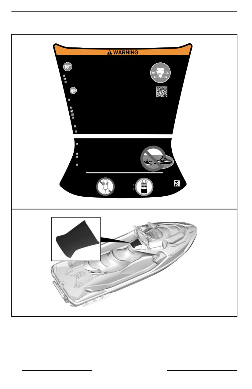
IMPORTANT ON-PRODUCT LABELS
General Information – Warning Label
Require Proper Operation of the Boat
Improper operation can result in severe injury or death.
Operators Must Be Qualified
Make sure operator is 16 or older and has taken a boater safety course.
Your state (or province) may have additional requirements.
Operators Must Avoid Collisions
Scan constantly for people, objects and other watercraft.
Stay far enough away from others so you can always safely coast to a stop.
Do not release throttle when trying to steer away from objects-as with other
powerboats, you need throttle to steer.
Watch safety video.
Read Operator’s Guide
Protect All Riders
Wear shorts with neoprene (wet suit material) and an approved PFD (personal flotation device)
- see Rider Safety section of this label.
Tell riders to read the Rider Safety section and make sure they are dressed appropriately.
Do not apply throttle when anyone is boarding or at rear of PWC.
Be sure riders are properly seated and holding on.
Avoid aggressive operation, sharp turns, and unexpected acceleration that can cause riders to be thrown off.
Do not jump waves or wakes - jumping can cause injuries such as back or spinal injuries (paralysis).
Do Not Permit Reckless Operation:
Do not go near others to spray or splash them with water, go too close to other boats, or go too fast
for traffic conditions.
Never ride after consuming alcohol or drugs.
RIDER SAFETY
Falls Can Result in Severe Injury or Death
You must wear shorts with neoprene (wet suit material) to keep water from being
forcefully injected into rectum or vagina during a fall backward.
Riders not wearing neoprene shorts have received severe rectal,
vaginal, and internal injuries resulting in permanent damage.
You must wear an approved PFD (personal flotation device).
Be sure you are properly seated and holding on.
Riders can be thrown off PWC during unexpected acceleration or
aggressive operation.
Never ride after consuming alcohol or drugs.
Do not ride if you are not dressed
appropriately.
5632
Patents :
Wear PFD
about-brp/patents
.html
Wear Neoprene
See Operator’s Guide
GENERAL INFORMATION – WARNING LABEL
TYPICAL – LABEL LOCATION
Passenger Appropriate Attire - Warning Pictogram
34
SAFETY INFORMATION
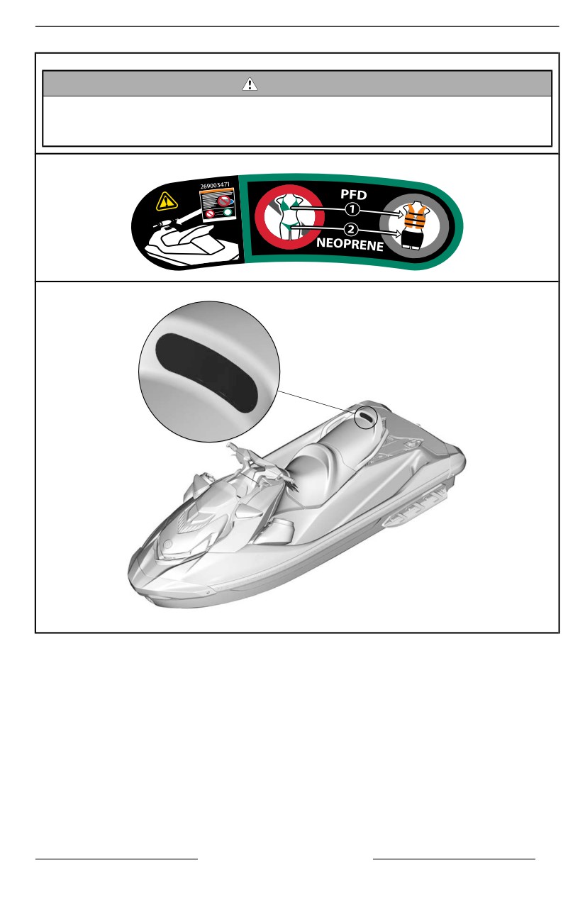
IMPORTANT ON-PRODUCT LABELS
WARNING
– Refer to the general safety labell llocated on the gllove box.
– Riiders must allways wear an approved PFD.
– Riiders must allways wear shorts wiith neoprene (wet-suit materiial).
TYPICAL – LABEL LOCATION
SAFETY INFORMATION
35
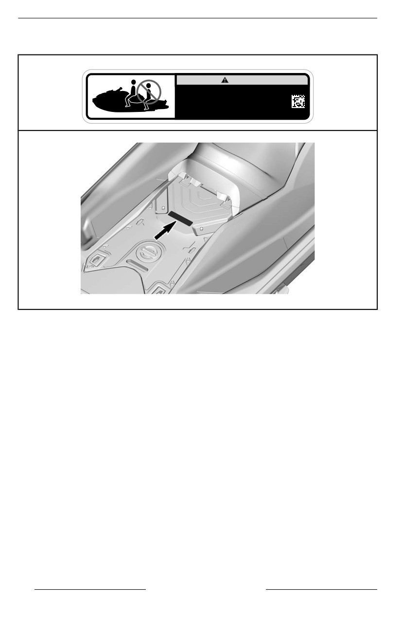
IMPORTANT ON-PRODUCT LABELS
Do Not Sit Pictogram - Warning Label
WARNING
If a Ski-Pylon can be used on this PWC, always install
the rear seat to prevent injury when in use.
Before riding the PWC make sure to properly
install and lock the seat(s) into place.
5978
LABEL LOCATION
36
SAFETY INFORMATION
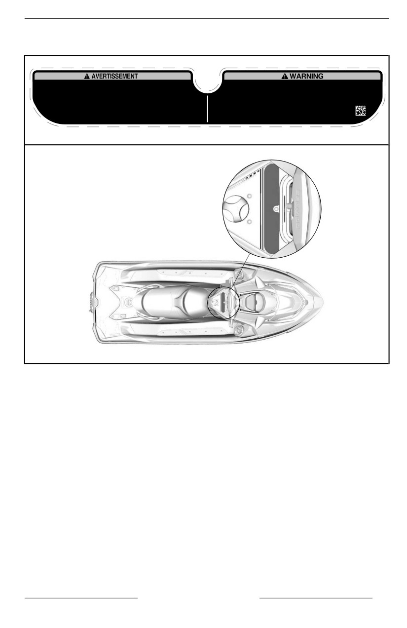
IMPORTANT ON-PRODUCT LABELS
Fueling Procedure - Warning Label
• Après avoir fait le plein toujours ouvrir le siège afin de s’assurer qu’il n’y ait pas d’émanation
• After refueling, always open the seat to ensure there is no gasoline vapor odor inside the
d’essence dans le compartiment moteur.
engine compartment.
• Les émanations d’essence peuvent provoquer des incendies ou des explosions.
• Gasoline vapor may cause fire or explosion.
• Éviter de trop remplir le réservoir d’essence. • Éviter de renverser de l'essence.
• Do not overfill gas tank. • Avoid spilling gasoline. • Wipe up spilled gasoline immediately.
• Essuyer immédiatement l'essence renversée • Garder la motomarine à l’écart des flammes et des
• Keep the watercraft away from open flames and sparks.
étincelles. • Ne pas démarrer la motomarine en présence d’essence liquide ou d’émanation
• Do not start watercraft if liquid gasoline or gasoline vapor odor is present.
d’essence. • Toujours remettre le siège en place avant de démarrer la motomarine.
• Always replace the seat before starting.
219905484
FUELING PROCEDURE - WARNING LABEL
TYPICAL – LABEL LOCATION
SAFETY INFORMATION
37
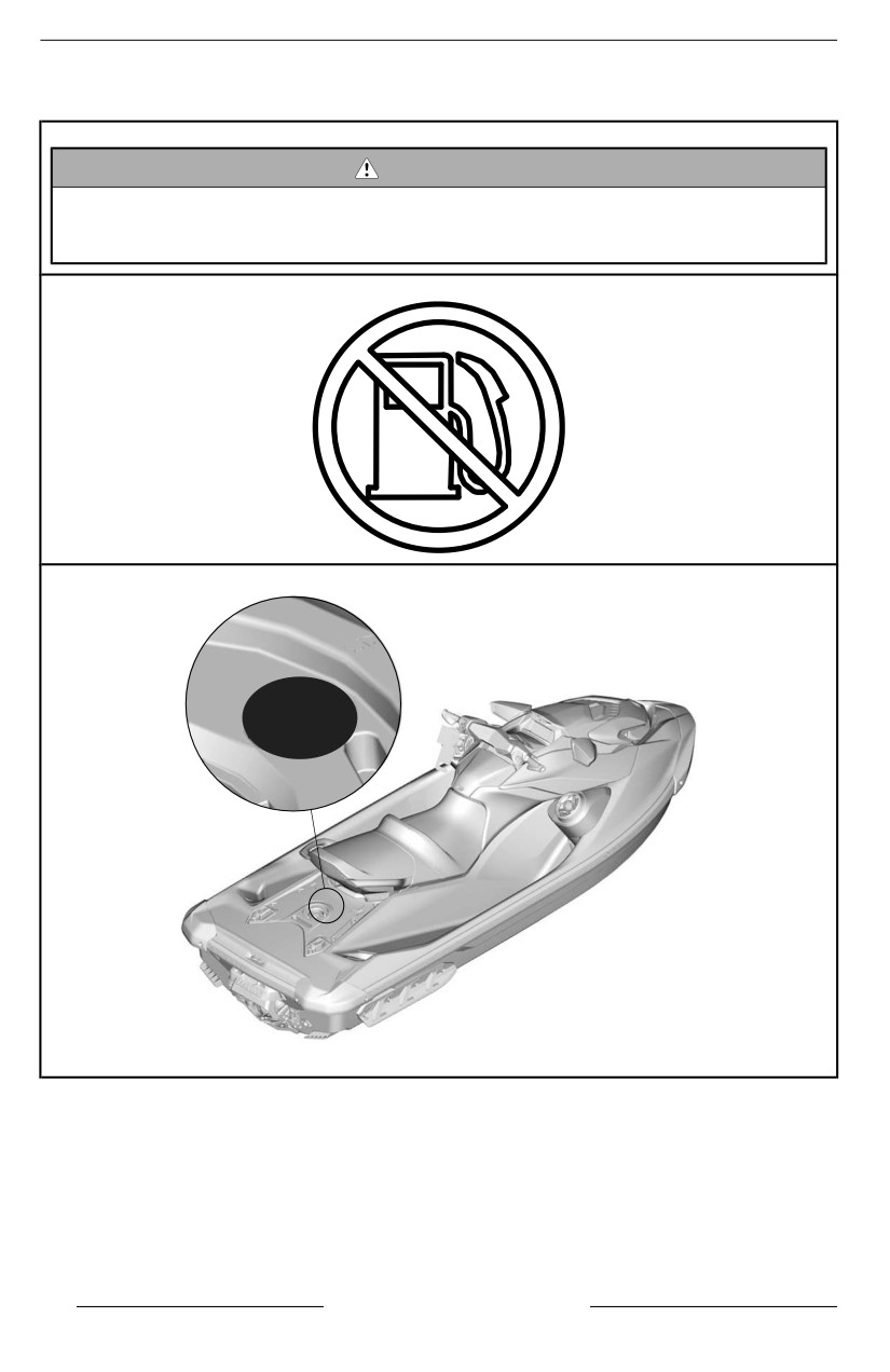
IMPORTANT ON-PRODUCT LABELS
No fuel – Warning Molded Pictogram
WARNING
Never put gasolline in this holle. Gasoliine iis extremelly fllammable and
hiighly explosive. Fuel vapors can spread and be iigniited by a spark or
fllame many feet away.
TYPICAL – LABEL LOCATION
38
SAFETY INFORMATION
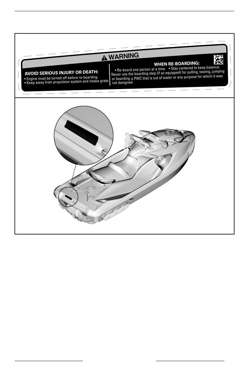
IMPORTANT ON-PRODUCT LABELS
Re-Boarding - Warning Label
219905498
TYPICAL – LABEL LOCATION
SAFETY INFORMATION
39
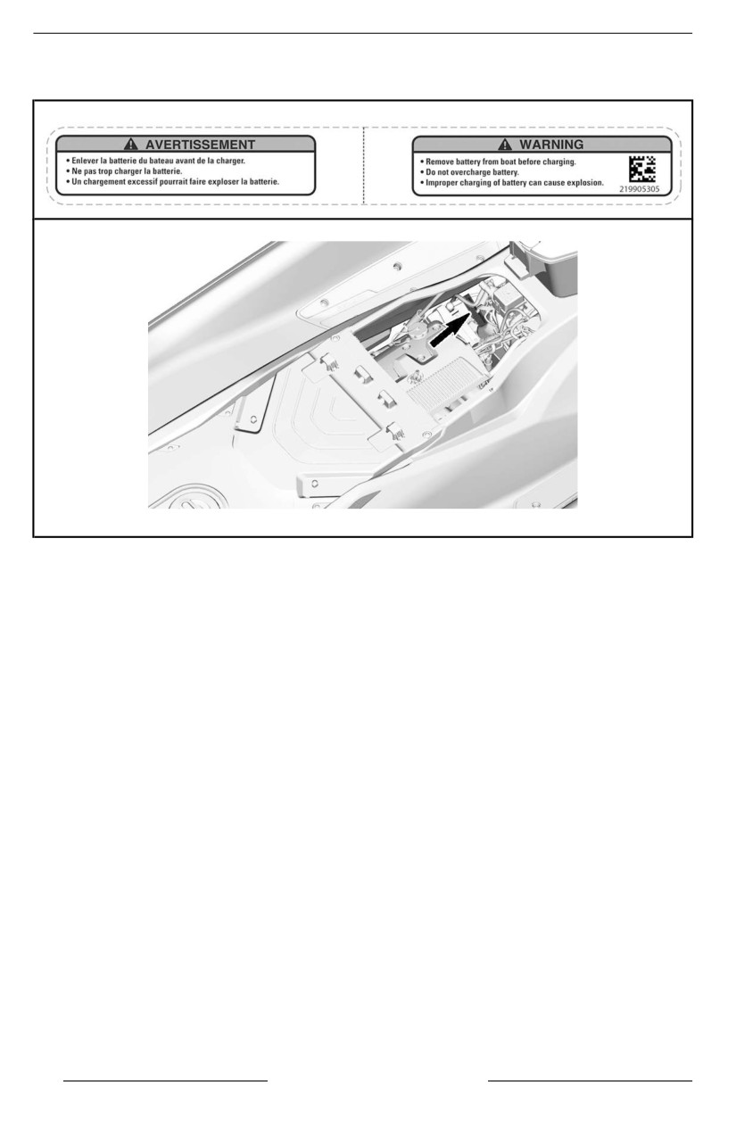
IMPORTANT ON-PRODUCT LABELS
Charging the Battery - Warning Label
TYPICAL – LABEL LOCATION
40
SAFETY INFORMATION
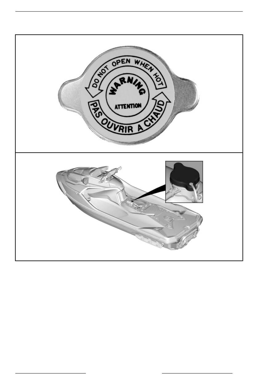
IMPORTANT ON-PRODUCT LABELS
Do Not Open When Hot - Warning Label
TYPICAL – LABEL LOCATION
SAFETY INFORMATION
41
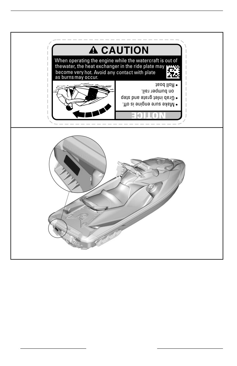
IMPORTANT ON-PRODUCT LABELS
Tip Over - Caution Label
219905494
TYPICAL – LABEL LOCATION
42
SAFETY INFORMATION
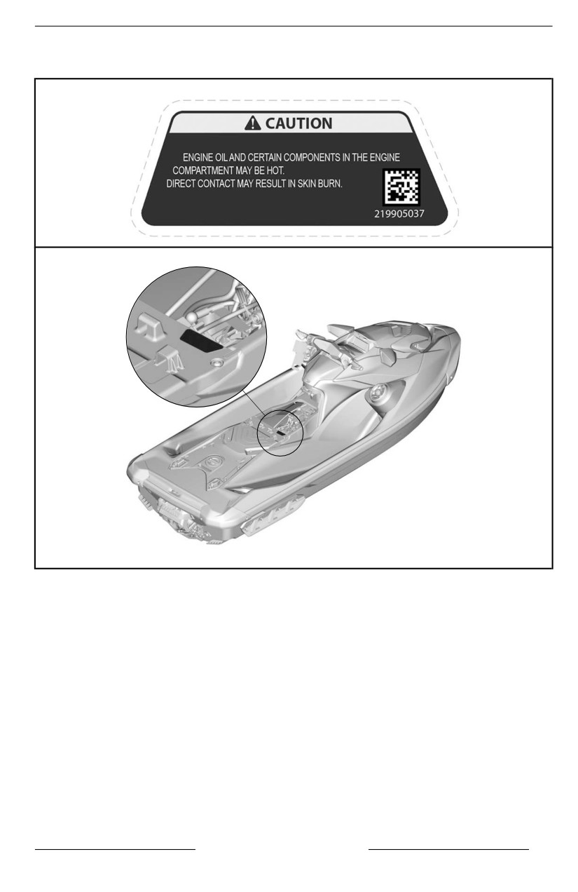
IMPORTANT ON-PRODUCT LABELS
Hot Components - Caution Label
TYPICAL – LABEL LOCATION
SAFETY INFORMATION
43
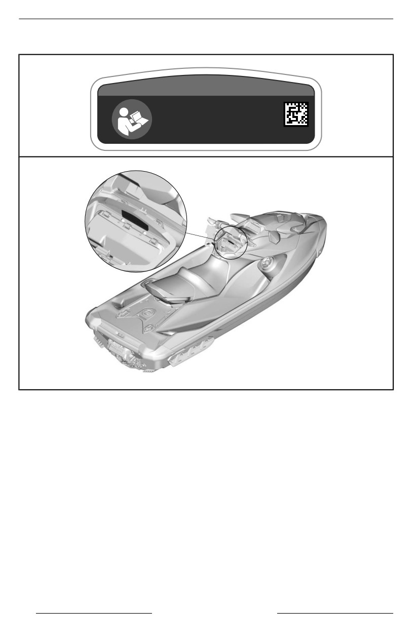
IMPORTANT ON-PRODUCT LABELS
Glove Box - Notice Label
NOTICE
Refer to the operator’s guide
for recommendations on
how to use the glove box .
5677
TYPICAL – LABEL LOCATION
44
SAFETY INFORMATION
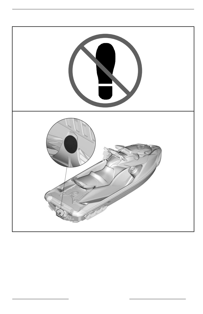
IMPORTANT ON-PRODUCT LABELS
Do Not Use to Onboard
TYPICAL – LABEL LOCATION
SAFETY INFORMATION
45
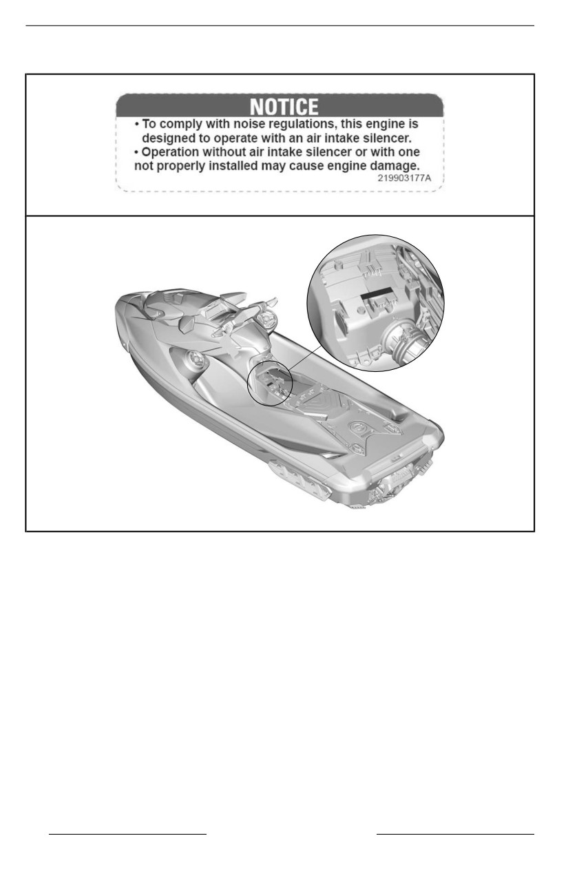
IMPORTANT ON-PRODUCT LABELS
Air Intake Silencer
AIR INTAKE SILENCER - NOTICE LABEL
TYPICAL – LABEL LOCATION
46
SAFETY INFORMATION
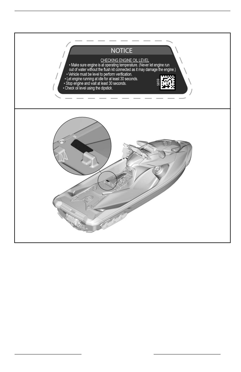
IMPORTANT ON-PRODUCT LABELS
Engine Oil Level
ENGINE OIL LEVEL - NOTICE LABEL
TYPICAL – LABEL LOCATION
SAFETY INFORMATION
47
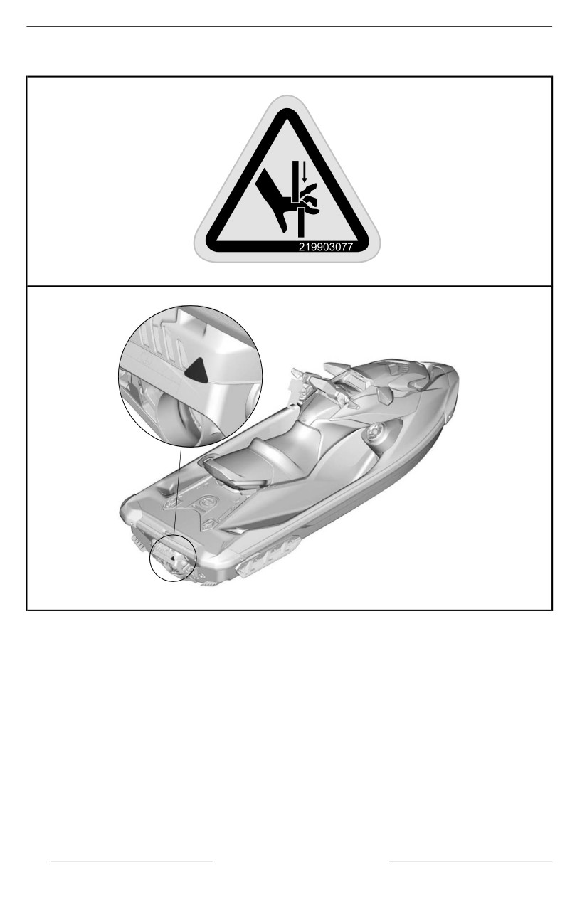
IMPORTANT ON-PRODUCT LABELS
iBR Gate
IBR GATE - WARNING LABEL
TYPICAL – LABEL LOCATION
48
SAFETY INFORMATION
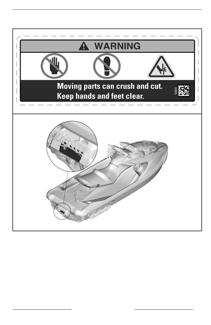
IMPORTANT ON-PRODUCT LABELS
iBR Gate - Warning Label
IBR GATE - WARNING LABEL
TYPICAL – LABEL LOCATION
SAFETY INFORMATION
49
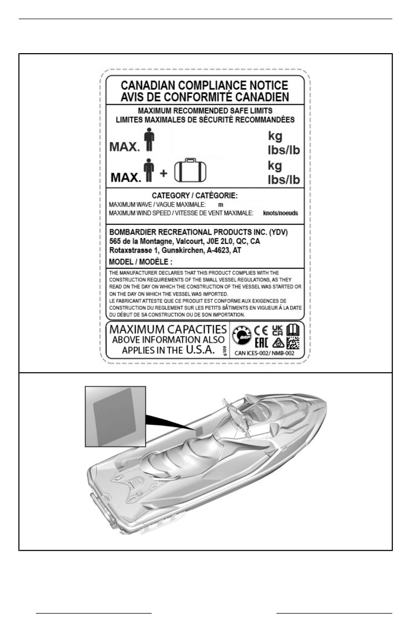
IMPORTANT ON-PRODUCT LABELS
Canadian Compliance Notice Label
TYPICAL – LABEL LOCATION
50
SAFETY INFORMATION
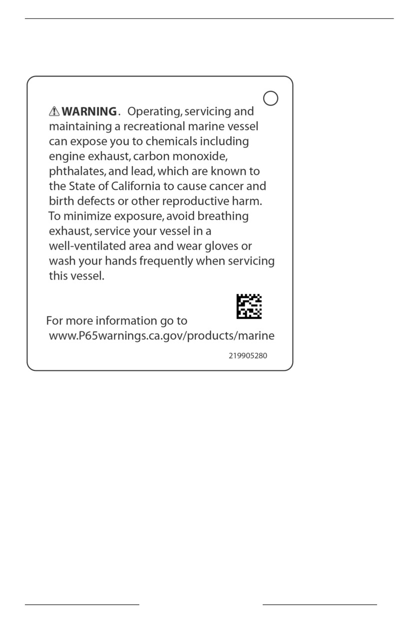
IMPORTANT ON-PRODUCT LABELS
Hang Tag
Callifornia Proposiition 65 Warning
SAFETY INFORMATION
51
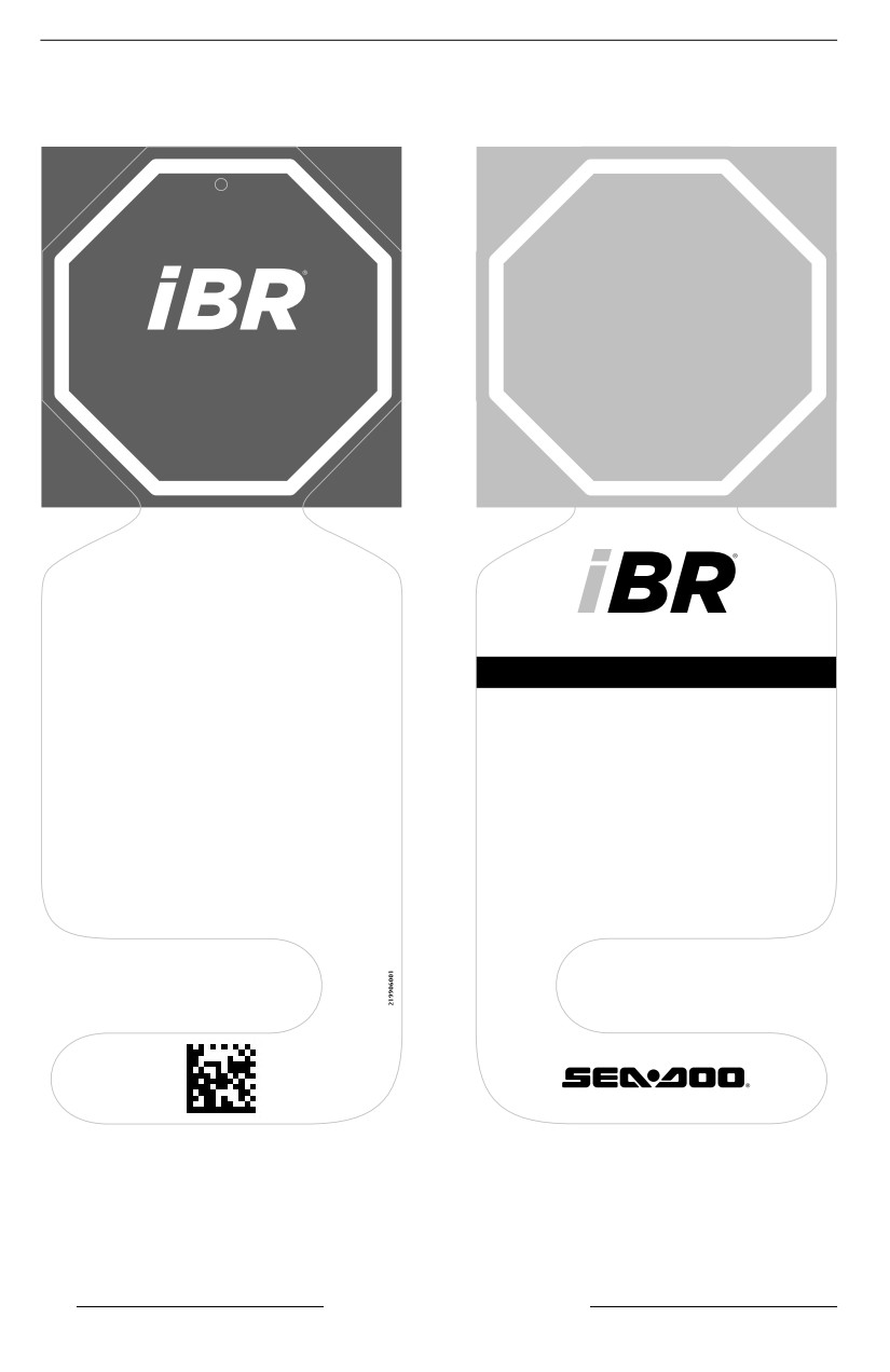
IMPORTANT ON-PRODUCT LABELS
i
iBR Hang Tag
STOP
INSTRUCTIONS
How to brake
• Squeeze brake lever.
INTELLIGENT BRAKE AND REVERSE
How to reverse
• Maintain brake lever engaged.
THIRD GENERATION
How to go forward
• Tap throttle lever to engage forward
• Allows you to stop sooner for greater
movement from neutral position.
peace of mind .
• Squeeze throttle lever to accelerate.
• Recognized by the U.S. Coast Guard for
improving boating safety since 2009.
How to get to neutral
• Tap brake lever.
• The Third Generation provides more
precise and responsive control when
braking and docking.
Refer to the operator’s guide for more information.
52
SAFETY INFORMATION
PRE-RIDE INSPECTION
Always inspect and confirm the safe operating condition of your vehicle prior to
ride.
Always follow the maintenance schedule described in this Operator's Guide.
WARNING
Perform a pre-riide inspection before each ride to detect potentiall prob-
l
lems during operation. The pre-riide iinspectiion can help you monitor wear
and deterioratiion before they become a probllem. Correct any problems
that you diiscover to reduce the riisk of a breakdown or crash.
Before using this vehicle, the operator should always perform the following pre--
ride inspection check list.
Refer to Maintenance Procedures for details.
What to Do Before Launching the Watercraft
WARNING
Engine shoulld be off and the tether cord cap shoulld allways be removed
from the engine cut-off switch priior to verifyiing any of the folllowing points.
Only start watercraft once alll items have been checked and operate
properlly.
NOTE: Before starting the engine and taking off, it is recommended to shake
vertically the rear of the watercraft to shake away any sand that may have accu-
mulated near the propulsion and reverse systems.
Check the items listed in the following table before launching the watercraft.
ITEM
OPERATION
Inspect hull, ride plate and
water inlet grate for damages.
Properly clean the hull before
Hull
launching the watercraft when
moving to a different water plan
to prevent from spreading
aquatic invasive species (AIS)
Jet pump water intake
Inspect/clean
Drain plugs
Tighten
Fuel tank
Refill
Check for any visible fluid leaks
Engine compartment
and gasoline vapor odor
Engine oil level
Check/refill
SAFETY INFORMATION
53
PRE-RIDE INSPECTION
Engine coolant level
Check/refill
Steering system
Check operation
Check operation. (Depress and
release the lever to check for
freedom of movement. If any
iTC lever
friction is felt in the throttle
lever, refer to an authorized
Sea-Doo dealer.)
Check operation. (Depress and
release the lever to check for
freedom of movement. If any
iBR lever (if equipped)
friction is felt in the iBR lever,
refer to an authorized Sea-Doo
dealer.)
Front storage compartment cover, glove
Ensure they are closed and
box and seat
latched.
Engine START/STOP button
Check operation
Engine cut-off switch and the monitoring
Check operation
beeper
Battery condition and connections
Check every month
Inspect every month (more
Sacrificial anodes
often in saltwater use) and
change if necessary
Hulll
Inspect hull for cracks and other damages.
Properly clean the hull before launching the watercraft when moving to a different
water plan to prevent from spreading aquatic invasive species. Refer to What to
Do After Leaving the Water at the end of this section.
Jet Pump Water Intake
Remove weeds, shells, debris or anything else that could restrict the flow of
water and damage the propulsion unit. Clean as necessary. If any obstruction
cannot be removed, refer to an authorized Sea-Doo dealer for servicing.
54
SAFETY INFORMATION
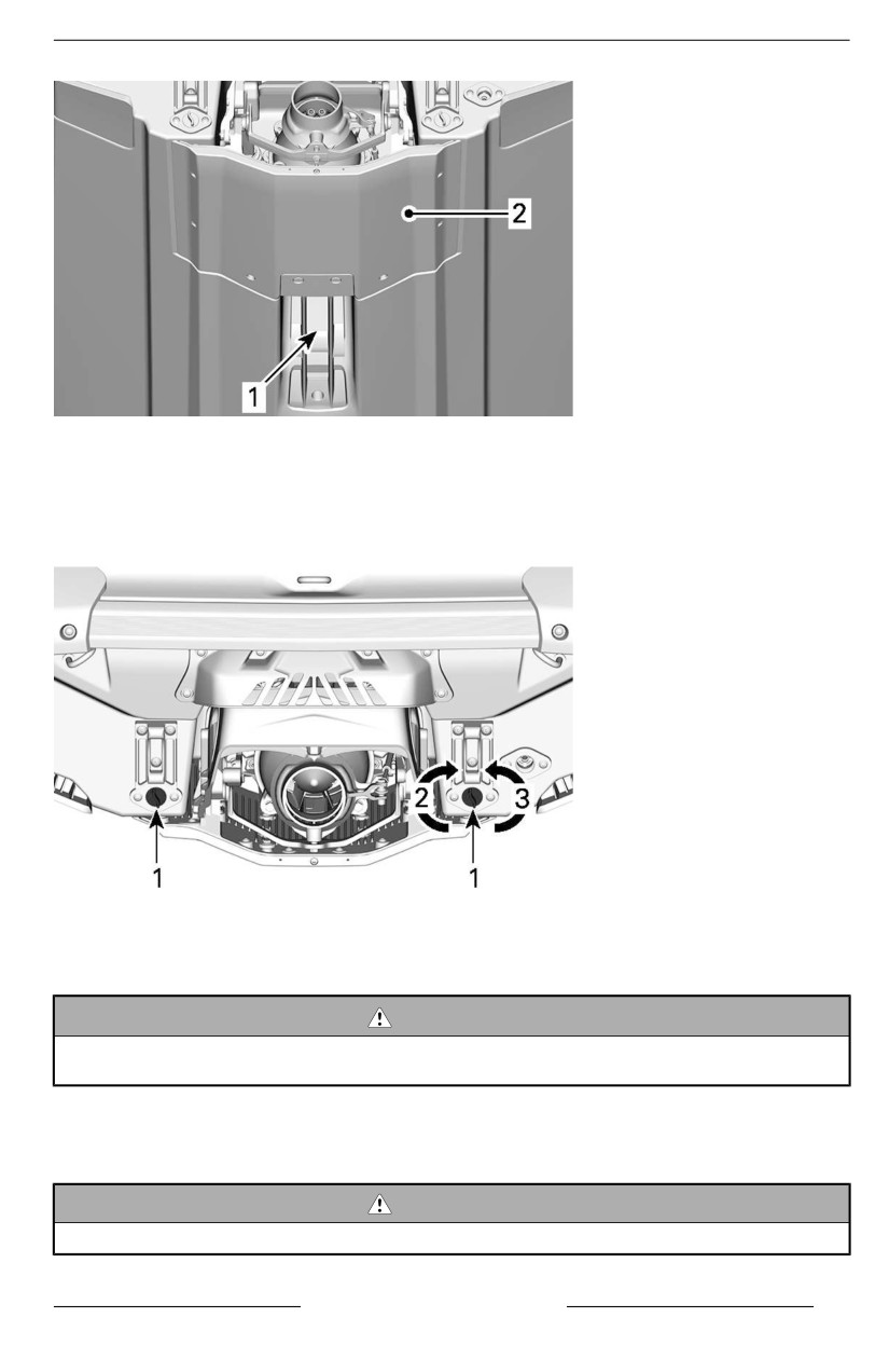
PRE-RIDE INSPECTION
1. Water intake
2. Ride plate
Draiin Plugs
Secure bilge drain plugs.
1. Bilge drain plug
2. Tighten
3. Untighten
WARNING
Ensure biilge drain plugs are properly secured priior to llaunching the
watercraft in water.
Fuel Tank
Fill the fuel tank.
WARNING
Striictly adhere to instructions detailled iin Fueling Procedure.
SAFETY INFORMATION
55
PRE-RIDE INSPECTION
Engiine Compartment
Inspect the engine compartment for fuel vapor odor.
WARNING
Shoulld any leak or gasoliine odor be present, do not applly ellectriicall
power or start the engiine. You shoulld seek service from an authoriized
Sea-Doo dealler, repair shop, or person of your own choosing for mainte-
nance, repair, or repllacement. Please refer to the US EPA Emiissiions-re-
l
lated warranty contaiined herein for informatiion about warranty claims.
To access the engine compartment, remove the seats. Refer to Removing the
Seat.
Engiine Oiil
Ensure oil level is within specification as described in Maintenance Procedures
section.
Engiine Coolant
Ensure coolant level is within specification as described in Maintenance Proce-
dures section.
Check for coolant leaks on engine, in bilge and from ride plate.
CAUTION
When operating the engine wiith the watercraft out of the water, the en-
giine and heat exchanger iin the riide pllate may become very hot. Avoid
any contact with hot engine parts and the ride plate as burns may occur.
Steering System
Assisted by another person, check steering operation for free movement.
When the handlebar is horizontal, the jet pump nozzle should be in the straight
ahead position. Ensure the jet pump nozzle pivots easily and in the same direc-
tion as the handlebar (e.g.: when handlebar is turned to the left, the nozzle open-
ing must point towards the LH side of watercraft).
WARNING
Check handllebar and corresponding steeriing nozzlle operation before
startiing. Never turn handlebar whiile someone is near the rear of the
watercraft. Keep away from steering moviing parts (nozzle, iBR gate, llink-
ages etc.).
i
iTC Lever (throttle control)
56
SAFETY INFORMATION
PRE-RIDE INSPECTION
Check the iTC lever for free and smooth operation. It should return to its initial po-
sition immediately after it is released.
WARNING
Check the iiTC llever operatiion before startiing the engiine. If any friction is
felt in the iTC lever, refer to an authoriized Sea-Doo dealer.
iBR Lever
Check the iBR lever for free and smooth operation. It should return to its initial
position immediately after it is released.
WARNING
Check iBR llever operation before startiing the engine. If any friictiion iis fellt
i
in the iBR llever, refer to an authoriized Sea-Doo dealer.
Storage Compartments, Boarding Pllatform and Seat
Ensure the glove box, boarding platform, access panels, and seat are closed and
latched.
WARNING
Ensure the seat, boarding platform, access panels, and alll storage com-
partment covers are securelly llatched.
Engine Cut-Off Swiitch and Engiine START/STOP Button
Press the start button once without installing the tether cordon the engine cut-off
switch.
Install the tether cord cap on the engine cut-off switch.
Press the START/STOP button to start the engine, then stop it by pressing the
START/STOP button a second time.
Restart the engine, then stop it by removing the tether cord from the engine cut--
off switch.
WARNING
Should the tether cord cap be loose or faill to remaiin on the engiine cut-off
swiitch, repllace the tether cord immediiatelly iin order to avoiid unsafe use.
If removing the tether cord cap from the engine cut-off switch or pressiing
the START/STOP button does not stop the engine, do not use the water-
craft. See your authorized Sea-Doo dealler.
SAFETY INFORMATION
57
PRE-RIDE INSPECTION
What to Do After Launching the Watercraft
Check the items listed in the following table after launching the watercraft and be-
fore going for a ride.
WARNING
Engiine should be off and the tether cord cap should always be removed
from the engine cut-off switch prior to verifying any of the folllowiing points.
Onlly start watercraft once alll iitems have been checked and operate , or if
required to perform a specifiic procedure.
NOTE: Before starting the engine and taking off, it is recommended to shake
vertically the rear of the watercraft to shake away any sand that may have accu-
mulated near the propulsion and reverse systems.
Check the items listed in the following table before launching the watercraft.
ITEM
OPERATION
Information Center
Check operation.
Intelligent Brake and Reverse System (iBR)
Check operation.
Variable Trim System (VTS)
Check operation.
Information Center (Gauge)
1. Press START/STOP button and install tether cord on the engine cut-off
switch.
2. As the information center cycles through its self-test function, ensure all indi-
cations come on.
WARNING
Always attach the tether cord clip to your PFD or to the wrist (wriist strap
required).
i
iBR System
NOTICE
Ensure there iis suffiiciient space ahead and behiind watercraft to safely
carry out the iiBR system test to avoid a collliisiion. Watercraft willl move
duriing test.
1. Remove the moorings lines securing the watercraft to the dock.
2. Start the engine and ensure the watercraft does not move.
3. On the left handlebar, depress the iBR lever completely in, the watercraft
should move slowly backwards.
58
SAFETY INFORMATION
PRE-RIDE INSPECTION
4. Release the iBR lever, there should not be any reverse thrust.
WARNING
Allways ensure proper iBR system operatiion before taking the watercraft
out for a ride.
Variable Trim System (VTS) (if equiipped)
With the engine running in forward thrust, use the VTS to move the jet pump noz-
zle up, and then down alternately to check VTS operation. Confirm the VTS posi-
tion indicator movement in the information center.
Also test the VTS preset trim positions by double clicking the VTS UP/DOWN
button (as applicable to model).
Refer to Operating Instructions for detailed instructions.
What to Do After Leaving the Water
Aquatic Invasive Species (AIS) are non-native plant or animal species that threat-
en the diversity or abundance of the native species. They also threaten the natu-
ral ecology of the body of water they infest. AIS almost always has a negative
impact on the waterway, it’s native species, and recreational or commercial
activities.
Common examples of AIS are:
- Eurasian Watermilfoil
- Hydrilla
- Sea Lampreys
- Zebra Mussels
- Asian Carp
- Gobies.
Many other examples of AIS exist throughout the world’s waterways.
A typical factor in AIS infestations is that the non-native species are introduced
by human activity. Some AIS are introduced by commercial operations; however,
AIS can be introduced through recreational boating activities. The transportation
of recreational watercraft and water sports equipment between waterways can
be a major factor in the spread of AIS.
As responsible watercraft owners, we MUST do our part to prevent the spread of
these aquatic hitchhikers. Check your watercraft each time you leave the water!
In many cases it is required by law, be sure to check the local regulations for the
waterways you visit.
Clean, Drain and Dry - Everything, Every Time!
After each boating trip, before you leave the water access, follow these three
simple steps to stop the spread of AIS. This is the boater’s way to help protect
the environment from the damage that AIS can cause.
Clean
SAFETY INFORMATION
59
PRE-RIDE INSPECTION
Inspect and remove any visible plants, fish, animals, mud, or other debris from
the watercraft (including hull, intake grate, and jet pump nozzle), trailer, and any
water sports equipment, gears and accessories before leaving the water body.
Clean all parts, equipment, and gear that came in contact with the water.
Drain
Drain and flush all water from the watercraft, exhaust system, bilge, pontoon
floats, and every conceivable space or item that can hold water.
Dispose of unwanted live bait in the trash.
Dry
Allow everything to dry completely (for 5 days or more, refer to local laws) before
visiting any other bodies of water.
60
SAFETY INFORMATION
ANNUAL SAFETY MAINTENANCE
BRP recommend to have an annual safety inspection of your vehicle. Contact an
authorized Sea-doo dealer for further details.
Though not required, it is recommended that an authorized BRP dealer performs
the preseason preparation of your vehicle.
Each visit to your authorized Sea-Doo dealer is a great opportunity for your deal-
er to verify if your vehicle is included in any safety campaign. We also urge you
to visit your authorized Sea-Doo dealer in a timely manner if you become aware
of any safety related campaigns.
SAFETY INFORMATION
61
SAFETY INFORMATION
This page is intentionally blank
62
SAFETY INFORMATION
WATERCRAFT
INFORMATION
63
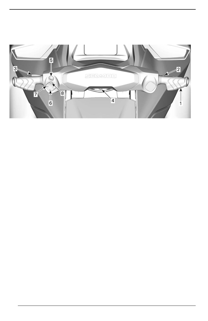
CONTROLS
Some vehicle safety labels are not
Some indications, functions and fea-
shown on illustrations. For information
tures described in this section may not
on vehicle safety labels, refer to Im-
apply to every PWC model, or may be
portant On-Product Labels.
available as an option.
1. Handlebar
2. Throttle Lever
3. iBR Lever (if equipped)
4. Engine Cut-Off Switch
5. Engine START/STOP Button
6. INFO Button
7. Mode Button
8. TRIP Button
64
CONTROLS
Handlebar
- Brake
- Reverse
The handlebar controls the direction
- Neutral.
of the watercraft. During forward oper-
ation, turning the handlebar to the
NOTE:
right steers the watercraft to the right
A minimum of 25% of iBR lever stroke
and inversely.
is required to activate iBR functions.
WARNING
Check handlebar and correspond-
i
ing steeriing nozzlle operation be-
fore startiing. Never turn the
handllebar whille someone iis near
the rear of the watercraft. Keep
away from the propullsion system.
When operating in reverse, the steer-
ing direction is reversed. Turning the
handlebar to the right while backing
TYPICAL
up steers the watercraft to the left.
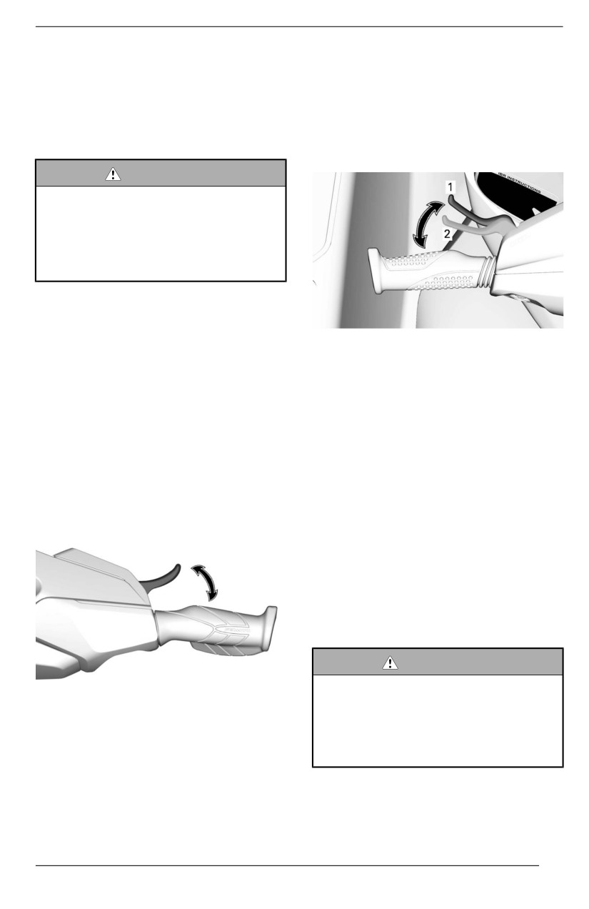
1. Lever rest position
2.
25% stroke required to activate iBR
Throttle Lever
functions
The throttle lever on the RH handlebar
At speed above 14 km/h (9 MPH),
controls electronically the engine
pulling the iBR lever will engage the
speed.
brake.
To increase or maintain watercraft
speed, pull the throttle lever with your
NOTE:
finger.
If the water current is
14 km/h (9
MPH) or above, the reverse can not
To decrease watercraft speed, re-
be engaged as the speed threshold
lease the throttle lever.
for the reverse is exceeded.
At speed below 14 km/h (9 MPH), pull-
ing the iBR lever will engage reverse.
When the iBR lever is released after
braking or reverse operation, the neu-
tral is engaged.
WARNING
If the throttlle llever iis stilll pullled in
The throttle lever is spring loaded and
when relleasiing the iBR llever, for-
should return to rest position
(idle)
ward movement wiilll be initiiated
when not pressed.
after a short dellay. If forward ac-
celeration is not desired, rellease
the throttle lever.
intelligent Brake and Reverse
(iBR) Lever (if equipped)
NOTE:
The iBR lever on the LH handlebar
The neutral position can be fine tuned
can electronically command:
by trimming the iBR system.
65
CONTROLS
Refer to Operating Instructions for de-
WARNING
tailed instructions.
Should the engine be stopped, the
brake function and alll watercraft
Engine Cut-Off Switch
directiionall control iis llost.
The engine cut-off switch is located in
the middle of the handlebar.
WARNING
Allways diisconnect tether cord
when watercraft is not in opera-
tion in order to prevent accidentall
engiine startiing or to avoiid unau-
thoriized use by others, chilldren,
and to prevent theft.
Radio Frequency Diigitallly Encoded
Securiity System (RF D.E.S.S.)
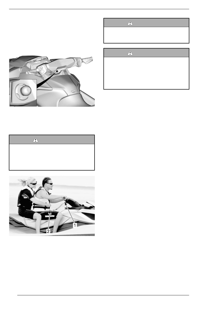
TYPICAL
The tether cord cap contains an elec-
tronic circuit (D. E. S. S.™ key) that is
To allow engine starting, the tether
programmed to give it a unique elec-
cord cap must be securely snapped to
tronic serial number. This is the equiv-
the engine cut-off switch.
alent of a conventional key.
The D.E.S.S. system reads the key in-
WARNING
stalled on the engine cut-off switch
Always attach the tether cord clip
and only allows engine starting for
to the operator''s personal flota-
keys it recognizes.
tiion device (PFD) or wriist (wriist
strap required) before startiing the
The D.E.S.S. system brings great flex-
vehicle.
ibility. You can buy additional tether
cords and have the D.E.S.S. keys pro-
grammed for your watercraft.
A total of ten D. E. S. S. keys can be
programmed.
To have a key programmed to your
watercraft, see your authorized BRP
Sea-Doo dealer.
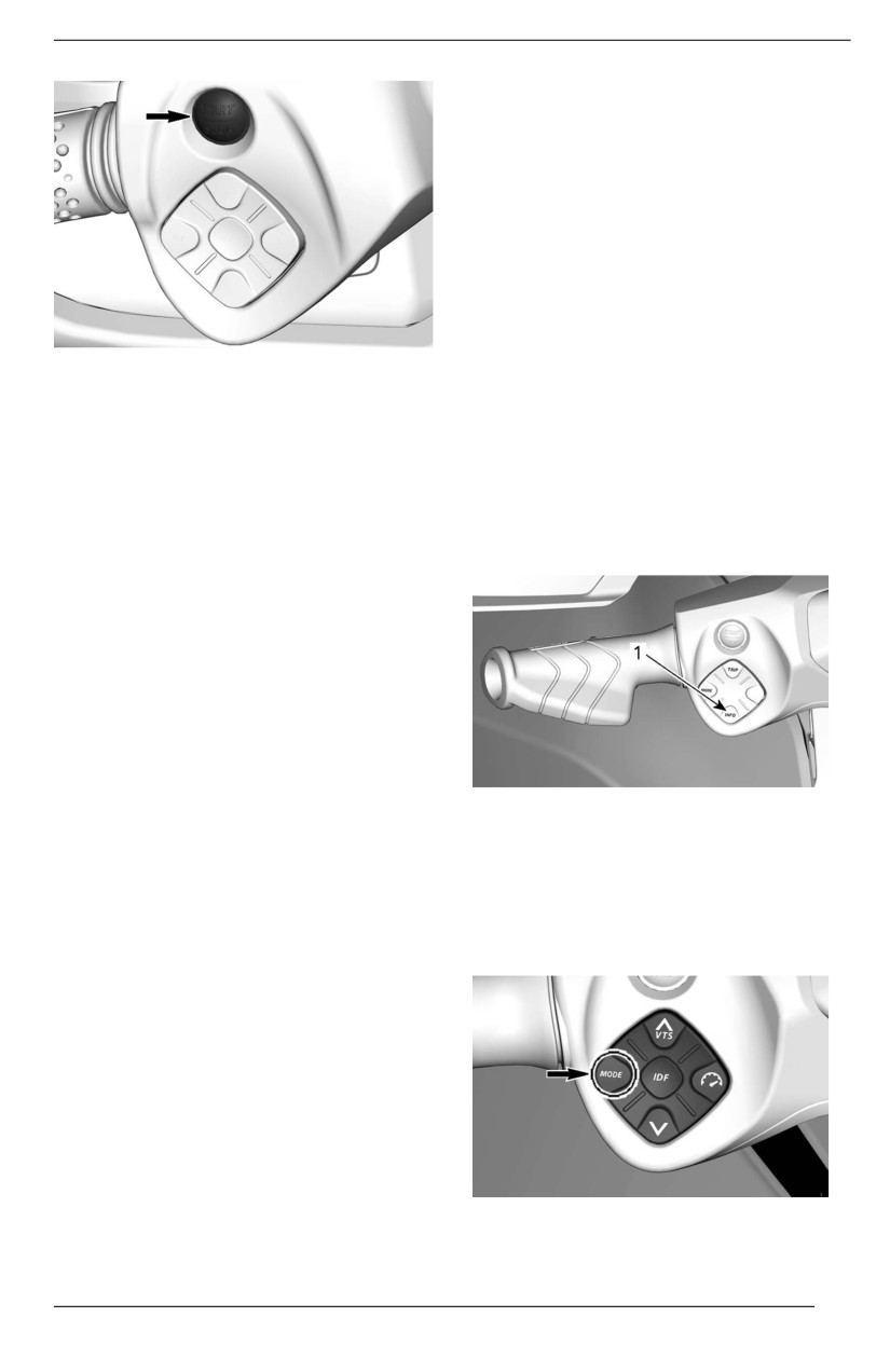
Engine START/STOP Button
The engine START/STOP button is lo-
cated on the LH handlebar.
TYPICAL
1. Tether cord cap on the engine cut-off switch
2. Tether cord secured to operator's PFD
To stop engine, pull the tether cord
cap from the engine cut-off switch.
66
CONTROLS
prevents draining the battery too
much when using accessories. When
the battery voltage reaches 12.3V or
less, the system will automatically
shut down to ensure enough power
remains to start the engine.
When the electrical system is acti-
vated by pressing START/STOP
briefly while the engine is shut down
the wake-up time will be managed as
follows:
TYPICAL
–
ENGINE START/STOP
- Key off: System will shut down
BUTTON
after 75 seconds.
- Key on: System will shut down
Engine Startiing and Stopping
after 60 minutes or if the voltage
threshold is reached.
Refer to Operating Instructions for
complete procedures on how to start
INFO Button (If Equipped)
and stop the engine.
The INFO button is located on the LH
Waking Up the Ellectrical System
handlebar.
Press the START/STOP button once
without installing the tether cord on
the engine cut-off switch.
This will power up the electrical sys-
tem; the information center will cycle
through a self-test function.
The electrical system will stay pow-
ered up for approximately 75 seconds
after the START/STOP button was
1. INFO button
depressed.
When the tether cord is installed on
It is used to navigate through the me-
the engine cut-off switch, the system
nus and to change some settings.
will be powered for
60 minutes (If
Refer to Operating Modes for details.
equipped).
Every time the START/STOP button is
Mode Button
pressed, the countdown restarts.
When the battery voltage drops below
12.3V, the LOW BATTERY indicator
lamp will light up and the electrical
system will shut down after
75
seconds.
Post-Drive Battery Management (If
equiipped)
This feature keeps the electrical sys-
tem awake to allow using accessories
TYPICAL
when the engine is turned off. It also
67
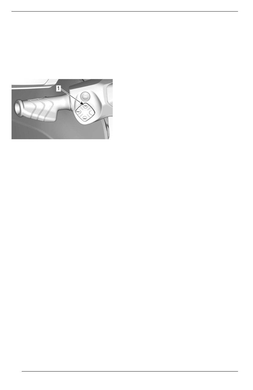
CONTROLS
It is used to choose between Normal,
Sport or Eco mode.
Refer to Operating Modes for details.
TRIP Button (If Equipped)
The TRIP button is located on the LH
handlebar.
1. TRIP button
It is used to cycle through the trip-
meter displays and the clock on the
upper left display.
Refer to Operating Modes for details.
68
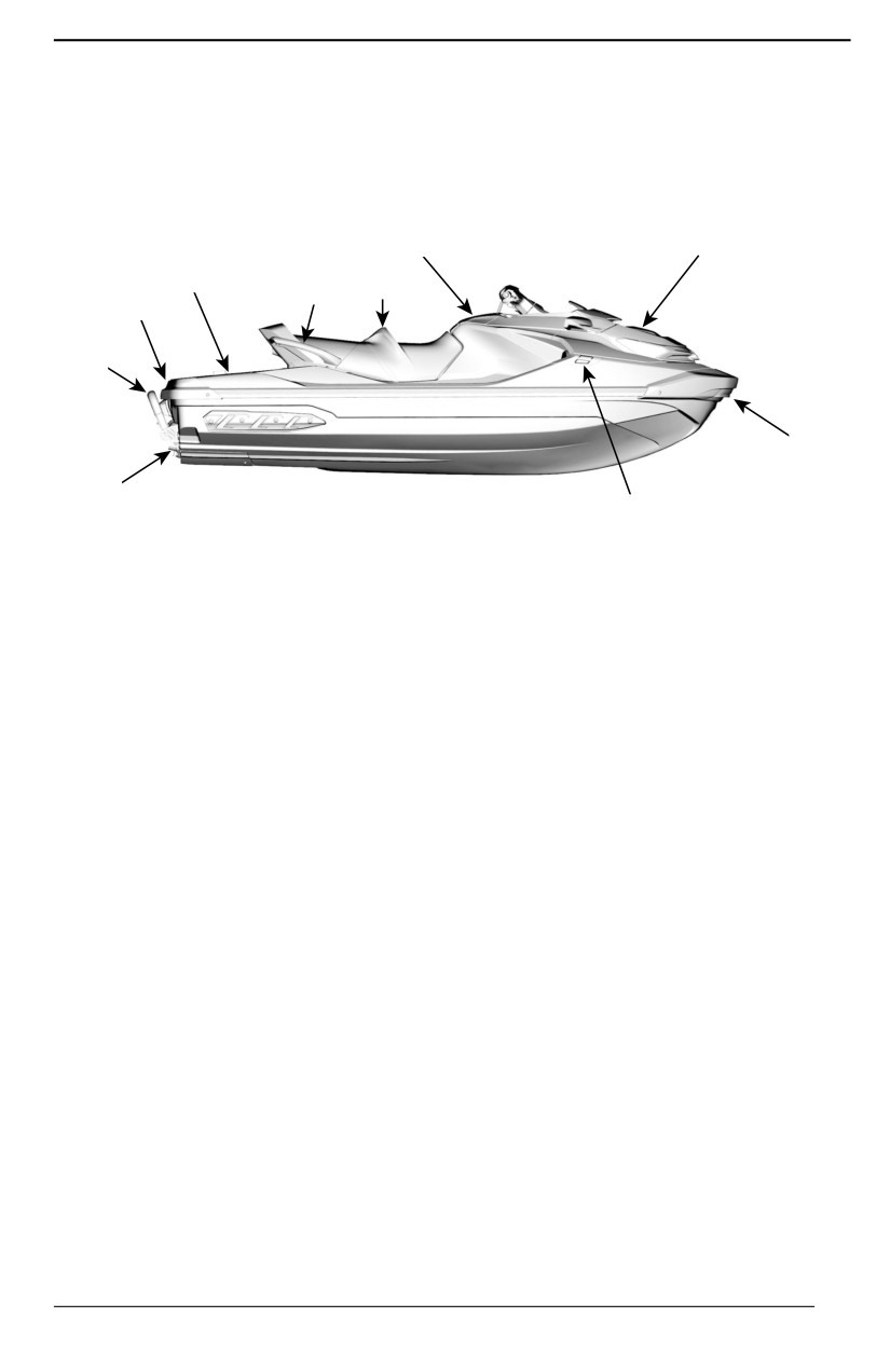
EQUIPMENT
Illustrations may not be accurate for
Some vehicle safety labels are not
every model and are only provided as
shown on illustrations. For information
a visual guide.
on vehicle safety labels, refer to
Watercraft Safety Labels.
1
2, 3, 4
8
5
6
10
7
9
11
10
1. Glove Box
2. Storage Bin
3. Fire Extinguisher Holder
4. Safety Kit Holder
5. Seat
6. Passenger Handholds
7. Boarding Ladder (If Equipped)
8. Boarding Platform
9. Front Eyelets
10. Mooring Cleats
11. Bilge Drain Plugs
69
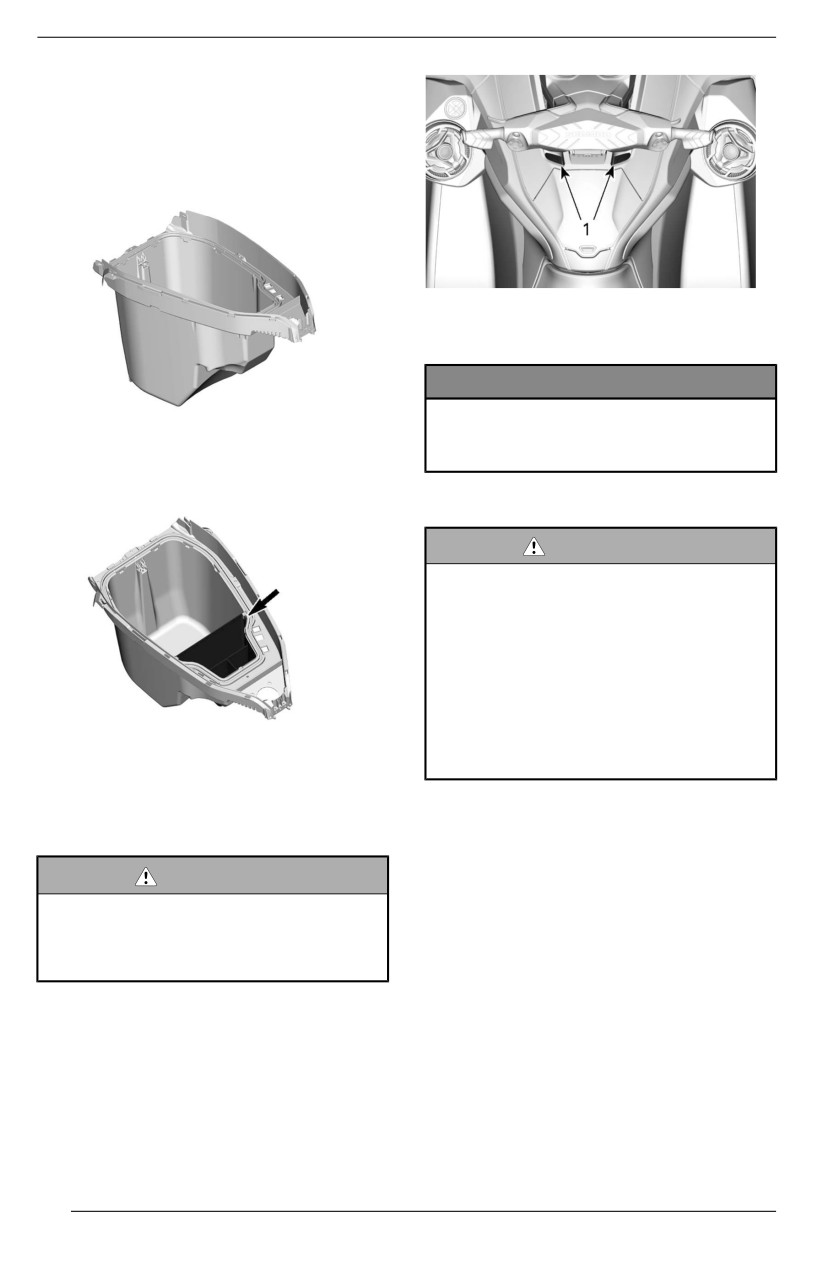
EQUIPMENT
Front Storage Compartment
The front storage compartment that
can be used to carry larger personal
articles is located under the front
cover.
1. Release buttons
NOTICE
The maxiimum load alllowable for
FRONT STORAGE COMPARTMENT
the front storage compartment iis
13 kg (30 lb) evenlly diistriibuted.
Front Storage Compartment
Organiizer Bag (If Equipped)
WARNING
Never leave any heavy or break-
ablle objjects loose iin the front
storage compartment. Do not
overlload.Never store or transport
fuell or any other flammablle prod-
ucts in this storage compartment.
Never operate the watercraft with
the storage compartment cover
1. Front Storage Compartment Organizer Bag
open or with improperly secured
cargo.
Openiing the Front Storage
Compartment Cover
Fire Extinguisher Holder
Stop engine.
NOTE:
WARNING
Fire extinguisher is sold separately.
When the front storage compart-
ment cover iis opened, the con-
The fire extinguisher support is lo-
trols are not accessible to the
cated under the front storage bin
driiver.
cover.
Use the rubber tie-downs to properly
Open the storage bin by pressing on
secure the fire extinguisher.
the two release buttons and lifting the
handlebar.
70
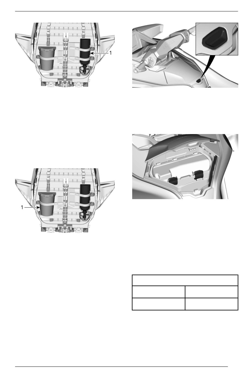
EQUIPMENT
1. Fire extinguisher
Watertight Compartment
Safety Kit Holder
Inside the glove box is located a small
watertight storage compartment for
NOTE:
personal articles. Pull backwards on
Safety kit is sold separately.
the two latches to open.
The safety kit support is located under
the front storage bin cover.
Use the rubber tie-downs to properly
secure the safety kit.
TYPICAL
There is a protective foam located in-
side the watertight compartment to
protect a phone from damages. Make
sure the smartphone is held in place
1. Safety Kit
by the foam and not the edges of the
receptacle and that you can close the
Glove Box
lid. Always make sure the foam is
completely dry before using.
A small, storage compartment for per-
sonal articles.
Refer to Maximum Phone Size chart.
Push on cover latch to open glove
Maximum Phone Siize
box.
Length
160 mm (6.3 in)
Width
85 mm (3.3 in)
NOTE:
Due to variation in smartphone sizes
and cases styles, ensure there is no
pressure on connector and/or phone
when closing the lid.
71
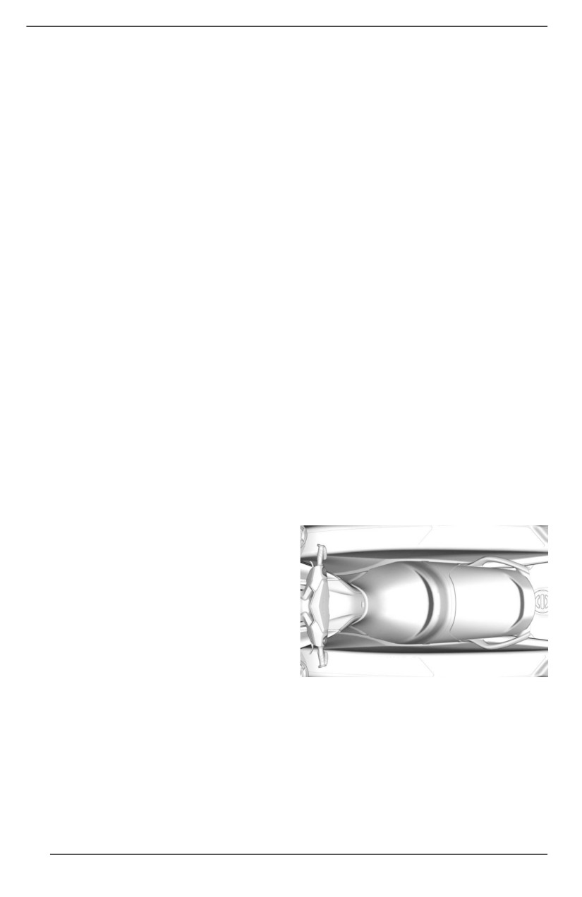
EQUIPMENT
Some models are equipped with a
- Completely dry the compartment
USB port used for charging. When us-
and its contents before closing.
ing the USB port to charge a smart-
- Make sure nothing gets pinched
phone, always make sure to route the
between cover and box when clos-
cable such that there is no pressure
ing compartment.
on either ends of the cable to prevent
- Always close the compartment
damage to cable or smartphone
completely using the 2 latches.
connectors.
After use:
NOTE:
- Remove smartphone from
For optimum performance, always
compartment.
use OEM USB cables. Low cost after-
- The USB charging port’s inte-
market cables may not have data lines
grated rubber cap should be in-
and/or higher impedance which may
stalled to cover the connector.
result in poor charging performance or
- Always close the compartment
overheating.
completely using the 2 latches.
Many models of smartphones have a
NOTE:
brittle female connector so extra care
Use of desiccant in the watertight
should be taken when inserting in the
compartment is recommended to
watertight compartment. BRP recom-
eliminate condensation. Replace des-
mends to use a short cable (no more
iccant frequently.
than 25 cm (10 in)) so there is less ex-
tra cable length to stow.
Seat
The models not equipped with USB
This model comes equipped with an
charging port are instead equipped
ergonomic seat narrowing towards the
with a rubber seal to ensure water-
front with knee grab design allowing
tightness. There is a ventilation mem-
you to position your legs towards the
brane that balance pressure inside
inside of the footwells, minimizing
and outside the compartment to en-
upper body fatigue and granting you
sure it can be opened without suction-
more control when cornering.
ing water droplets inside. The
membrane itself is watertight. Water-
tightness of the compartment is finally
ensured by pressing the compart-
ment’s door on the surrounding seal,
using the two latches.
To ensure that articles inside the com-
partment are protected from the envi-
ronment,
the
following
recommendations should be followed:
Before and during use:
ERGONOMIC SEAT
- Make sure the seal is intact,
Removing the Seat
cleared and properly positioned.
- Make sure the ventilation mem-
1. Push on the two release buttons
brane is intact and properly
and lift the back end of the rear
positioned.
seat.
- Make sure the seal around the
USB charging port (or rubber seal)
is intact and properly positioned.
72
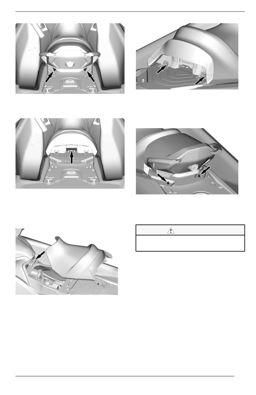
EQUIPMENT
SEAT RETAINERS
2. Then pull the latch handle up and
5. Align the seat latches with the
remove the front seat from the
latch pins and firmly press down
watercraft.
on the rear portion of the seat to
lock it in place.
Installliing the Seat
LATCH PINS
6. Pull up on the rear portion of the
1. To install the seat, insert the for-
seat to ensure it is properly
ward end of the front seat in its
latched.
retainer.
CAUTION
Ensure the llatch is properlly
l
locked onto the piin.
Passenger Handholds
The seat strap provides a handhold
for a passenger to hold on to when
riding.
The sides of the molded grab handle
SEAT RETAINER
at the rear of the seat also provide a
2. Push the rear end of the front seat
handhold for a passenger. The rear
down to lock it.
portion of the molded grab handle pro-
3. Pull upwards on the front seat to
vides a handhold for the skier/wake-
make sure it is locked in place.
boarder
(if applicable) spotter or
4. Insert the forward part of the rear
seat into the retainers.
73
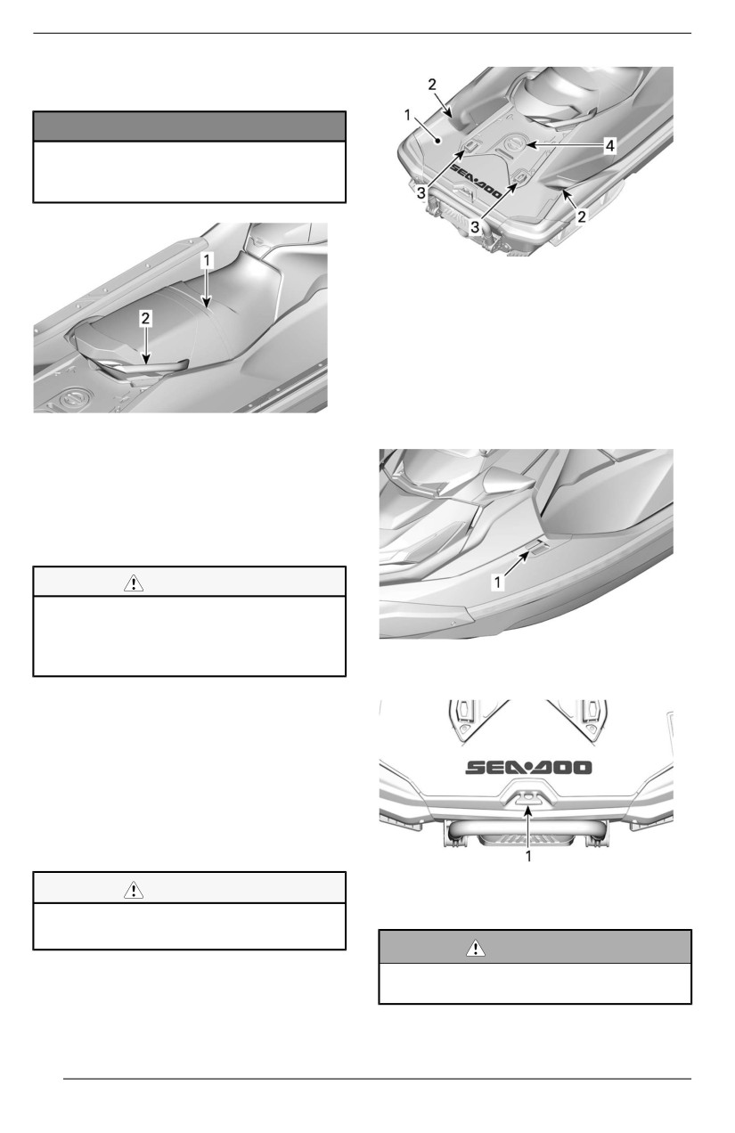
EQUIPMENT
boarding the watercraft from the
water.
NOTICE
Never use the mollded grab han-
dlle to tow anythiing or to liift the
watercraft.
1. Boarding platform
2. Spotter foot rests
3. LinQ attachments
4. Ski pylon hole cover
Mooring Cleats
These cleats can be used for docking.
The rear cleat can be used to tow an
TYPICAL
inflatable tube.
1. Seat strap
2. Molded grab handle
Boarding Platform
A boarding platform covers the rear
deck area.
CAUTION
The two LiinQ attachment poiints
are used to carry accessoriies and
should always be retracted when
TYPICAL
not in use.
1. Mooring cleats
Two indentations in the platform are
used as foot rests for the rear facing
spotter when towing a skier, wake-
boarder or tuber.
A ski pylon can be installed by remov-
ing the ski pylon hole cover in the mid-
dle of the platform. The ski pylon hole
cover is not the fuel cap.
CAUTION
1. Mooring cleat
Always iinstalll ski pyllon hole cover
when ski pylon iis not installled.
WARNING
Never use mooring cleats to pull
or liift the watercraft.
74
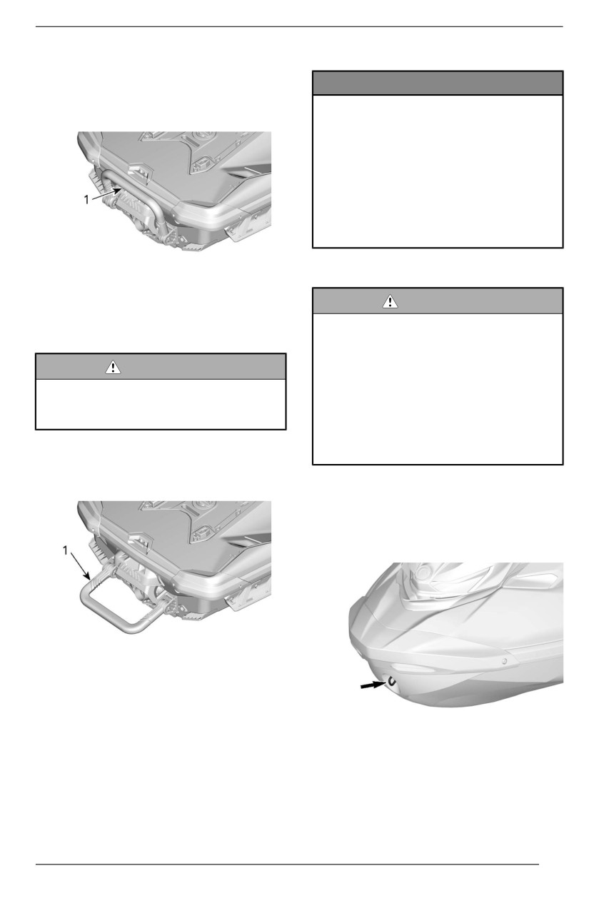
EQUIPMENT
Boarding Ladder (If
Equipped)
NOTICE
A convenient ladder used for boarding
– Never use the ladder for
the watercraft from the water.
boardiing a watercraft that iis
out of water.
– Never use the ladder for pull-
ing, towing, diving or jumping,
or any other purpose other
than as a boarding ladder.
– Stay on center of the ladder.
– Onlly one person at a tiime on
the lladder.
TYPICAL
WARNING
1. Boarding ladder
Be aware of the iBR gate move-
ment when starting the engine,
shuttiing down the engiine or using
WARNING
the iBR llever. Automatiic move-
ment of the gate may squeeze fin-
Do not applly throttlle when anyone
gers or toes of people takiing a
i
is boarding or at rear of water-
holld on the back or your water-
craft. Shut down the engiine
craft.Never use iiBR gate as a sup-
porting point to board the
Pull down the ladder with your hand
watercraft.
and hold until a foot or a knee is put
on the ladder.
Front and Rear Eyelets
Eyelets can be used for mooring, tow-
ing and as tie-down points when trai-
lering your watercraft.
TYPICAL
1. Boarding ladder in lowered position
TYPICAL – FRONT EYELET
75
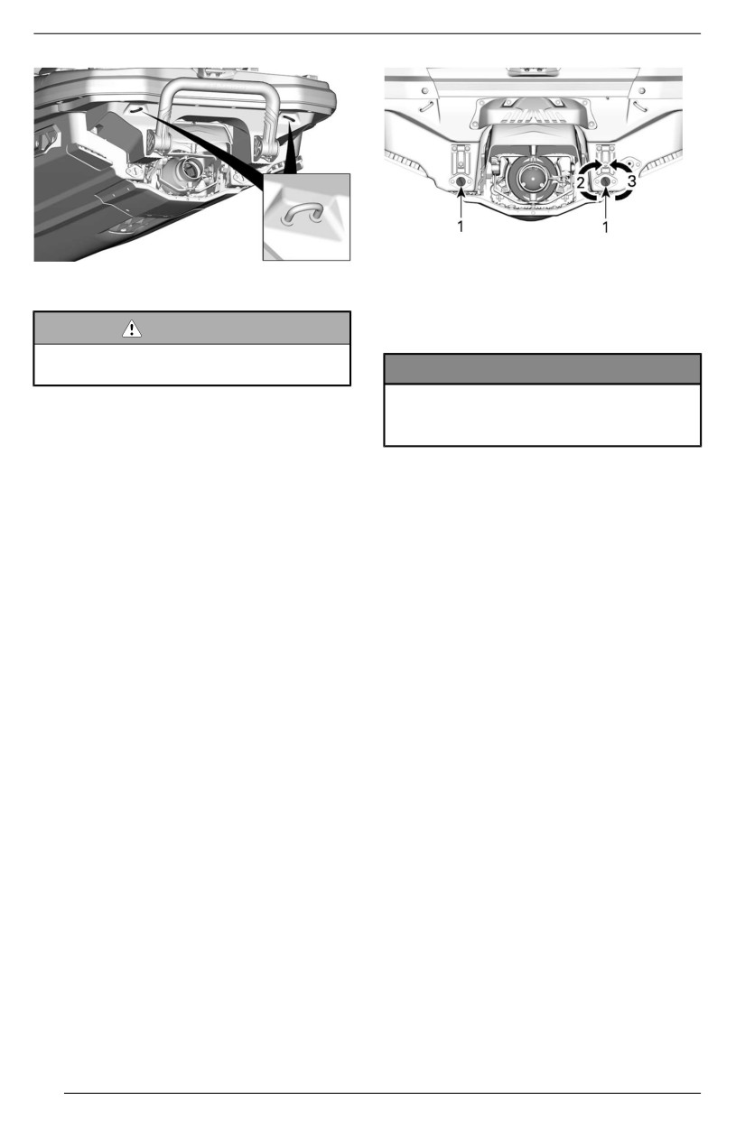
EQUIPMENT
TYPICAL
REAR EYELETS
1. Drain plugs
2. Tighten
WARNING
3. Loosen
Do not use these eyelets to llift the
watercraft.
NOTICE
Ensure drain pllugs are properly
secured priior to llaunching the
watercraft in water.
NOTE:
- Responsibiiliity: It is the owner’s/
operator's responsibility to ensure
that mooring lines, towing lines,
anchor chain(s), anchor lines and
anchor(s) are adequate for the
vessel’s intended use, i.e. the lines
or chains do not exceed 80 % of
the breaking strength of the re-
spective strong point. Owners
should also consider what action
will be necessary when securing a
tow line on board.
- Non-metallliic strong points:
Where non-metallic strong points
are installed, their limited life time
shall be taken into consideration.
They shall be replaced once they
show any signs of deterioration,
visible surface cracks or perma-
nent deformation.
Bilge Drain Plugs
Unscrew drain plugs whenever water-
craft is on the trailer. This will allow
water accumulated in the bilge to be
evacuated and helps to reduce
condensation.
76
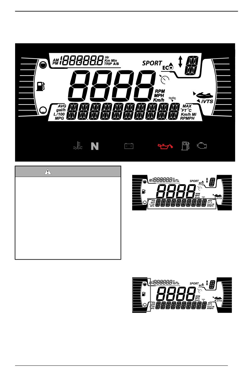
4.5" DIGITAL DISPLAY
Multifunction Gauge
Description
Lower Display
WARNING
Readiing or tamperiing wiith the
multiifunctiion gauge can distract
you from the operatiion of the ve-
hicle, and particularlly from con-
stantly scanning the environment.
Allways pay attention to water con-
ditiions, and ensure your environ-
User can decide to display one the
ment is cllear and free from
following:
obstacles.
- RPM
Furthermore, when riidiing, only
- Depth (if equipped)
glance at the mulltifunction gauge
- Settings
briefly to stay focused on your
- Messages
enviironment.
- Speed Stat (if equipped)
The multifunction gauge includes digi-
Left Laterall Diispllay
tal gauges (temperature and tachome-
ter), telltale lights, icons and a digital
screen to see important information
(speed, RPM, etc.).
The left lateral display includes:
- Fuel level indicator
77
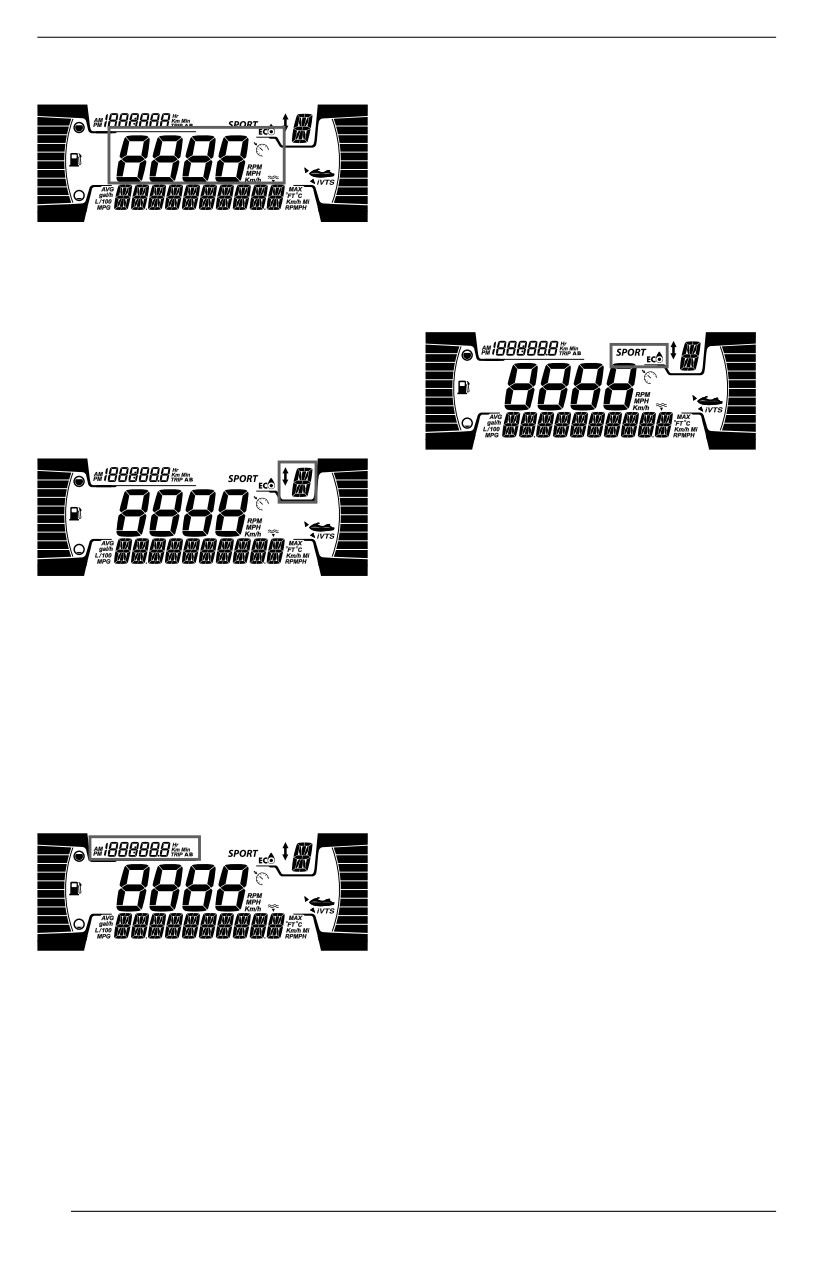
4.5" DIGITAL DISPLAY
Central Diispllay
- Trip KM : Displays the distance
since the last reset.
- Trip HR : Displays the time since
the last reset.
NOTE:
The clock is shown only if the inte-
grated GPS receives a signal from the
The central display includes:
satellites. This may take several sec-
onds after waking up the system.
- Watercraft speed
- Speed control indicator (if
MODE Diispllay
equipped)
The speed control indicator in this dis-
play is only activated when a target
speed is set.
i
iBR Position Displlay
The MODE display indicate the se-
lected alternative mode of operation:
- SPORT
- ECO
To cycle through the MODES;
This display shows the iBR gear posi-
- Press MODE button,
tion (if equipped):
- Acknowledge the safety message
- N (neutral)
by pressing and holding MODE
- F (forward)
button will get the SPORT mode,
- R (reverse)
- Pressing MODE button again will
cycle to Trixx mode, Ackknoledge
It can also display the selected speed
the safety message by pressing
level
(1 to 9) when the slow speed
and holding MODE.
mode is selected.
- Pressing MODE button again will
activate the ECO mode.
Left Upper Diisplay
Warning Lamps and
Indicators
The following indicator lamps will alert
you to a vehicle condition that may be-
come serious. Some lamps will illumi-
nate when starting the vehicle to
The left lateral display includes:
make sure they work. If any lamps re-
main on after starting the vehicle, refer
- Tripmeter
- Clock
The tripmeter cycles through the
following:
- Watercraft hours : Displays the to-
tal vehicle hours
78
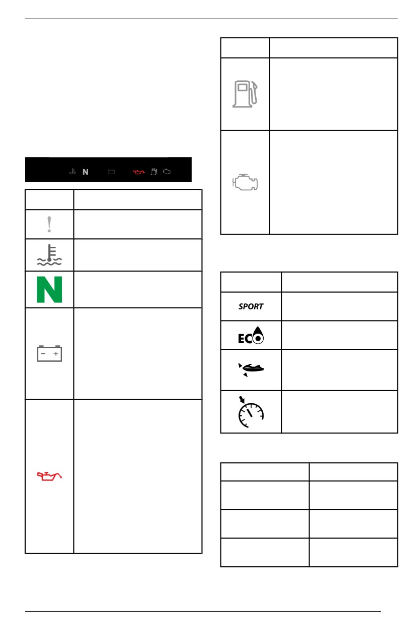
4.5" DIGITAL DISPLAY
to the respective system warning lamp
Liights
Descriiptiion
for further information.
ORANGE - Illuminated
NOTE:
when the fuel level is low
Some warning indicators appear in
or when the fuel tank is
the display of the multifunction gauge
near empty.
and function the same as an indicator
Refuel as soon as
lamp but do not display when starting
possible.
the vehicle.
ORANGE
Tellltalle Liights - Lower Bar
Turned on: Malfunction
of the vehicle emissions
control system
Bllink: Engine limitation,
limp home mode is
Lights
Description
activated. Have the
vehicle serviced
ORANGE - Vehicle
immediately.
malfunction
RED - The engine
Icons and Indicators - Multiifunctiion
temperature is too high.
Display
GREEN - The neutral
Icons
Description
gear is selected
Denotes SPORT
mode is selected.
RED - If illuminated while
driving, it indicates a
Denotes ECO mode is
malfunction.
selected.
Turn off all unnecessary
electrical equipment and
Steady ON: indicates
have the electrical and
that the VTS is
charging systems
activated (if equipped).
checked.
Denotes Speed
RED - If illuminated while
Limiter or Slow Speed
the engine is running or
mode (if equipped)
while driving, this
indicates a malfunction.
Stop the vehicle as soon
Settings
as it is safe to do so and
turn the engine off.
To...
Action
Check the engine oil
level.
Navigate in the
Single press on
Have the lubrication
menu
INFO
system checked a soon
Long press
as possible, even if the
Enter menu
INFO
level appears to be
correct.
Single press on
Edit value
INFO
79
4.5" DIGITAL DISPLAY
DOWN arrow button to set the desired
To...
Action
learning key level between 1 and 5.
Change
Press and hold OK button to confirm.
information
Press TRIP
display
NOTE:
The default learning key level is
1
Reset Trip
Long press
(lowest performance).
(when
TRIP
displayed)
Unit Sellectiion
Fault codes/
Long press
Select UNITS and press UP or
Maintenance
INFO
DOWN arrow button to change units.
NOTE:
Use the RIGHT arrow button or LEFT
Changing units will apply to all the dis-
arrow button to navigate through set-
played units.
ting menus. Use OK button to enter
setting menu, to confirm selection or
Settiing Brightness
reset some values. Use UP arrow or
DOWN arrow to change selected
Select BRIGHTNESS and press UP
value.
or DOWN arrow button to adjust
brightness level (from -4 to 4).
Settings Menu
Settiing Clock
Using the RIGHT or LEFT arrow but-
Select CLOCK.
ton, select SETTINGS and press OK
button to enter setting menus.
1. Press INFO button to select clock
display.
Maiintenance Reset
2. Long press INFO button to enter
Select RES MAINT and hold OK but-
clock editing.
ton to reset maintenance.
3. Press INFO button to select 12:00
AM PM or 24:00 time base.
NOTE:
4. Long press INFO button to confirm
The maintenance reset can only be
and display hours.
done within the first
15 seconds of
5. Press INFO button to change
ECM wake-up when a maintenance is
hours.
required.
6. Long press INFO button to
confirm.
Display Codes
Refer to Displaying Fault Codes.
NOTE:
Menu available only if GPS is
Setting Triipmeter
synchronized.
Select TRIP and press Trip to cycle
through Vehicle Hours, Trip KM and
To exit SETTINGS, long press Info
Triip HR.
button.
Press and hold Trip to reset selected
Resetting Speed Statiistiics (If
trip info.
Equipped)
Select SPEED STAT and press and
Setting Learniing Key (iif equipped)
Connect a normal key to the vehicle.
Select L-KEY
# and press UP or
80
4.5" DIGITAL DISPLAY
hold OK button to reset the speed
statistics.
NOTE:
The speed statistics are automatically
reset after the gauge shut down.
Settiing Language
The language of the display is factory
setup by default in English. Refer to
an authorized Sea-Doo dealer for lan-
guage availability and to setup the
gauge to your preference.
81
BREAK-IN PERIOD
Operation During Break-In
Period
A break-in period of 5 operating hours
is recommended before running the
watercraft at sustained full throttle.
During this period, maximum throttle
should not exceed 1/2 to 3/4 opening.
However, brief full acceleration and
speed variations contribute to a good
break-in.
NOTICE
Contiinued wide open throttle ac-
celerations or operatiion, pro-
l
longed cruising speeds are
detrimental during the break-iin
periiod.
NOTE:
During the first 3 hours of operation,
the engine management limits the en-
gine maximum speed for engine pro-
tection. The engine performance will
progressively increase during this
period.
82
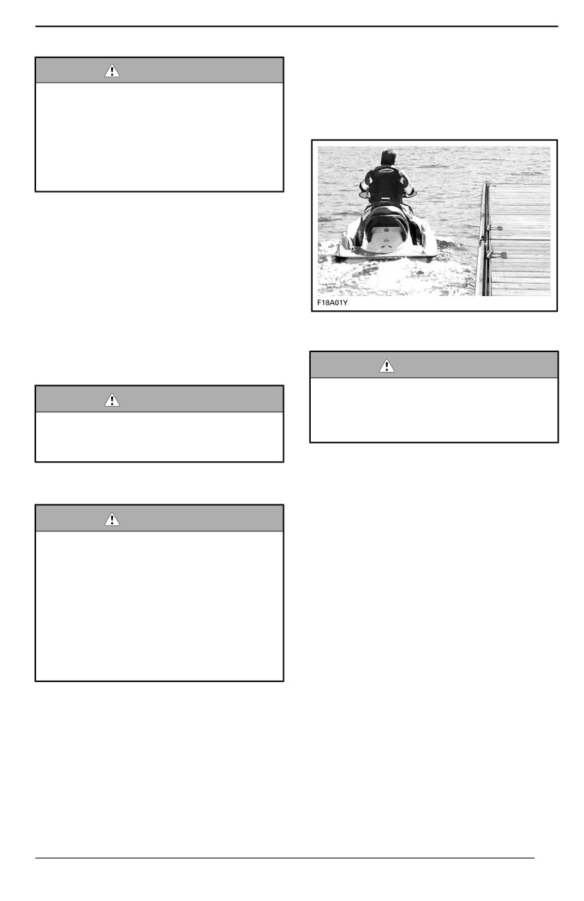
OPERATING INSTRUCTIONS
2. Then bring the other foot over the
WARNING
seat and place it on the other
Allways perform the Pre-Riide In-
footboard.
spection before operating thiis
3. Push the watercraft away from the
watercraft. Be sure to read the
dock.
Safety Information and the Water-
craft Information sections and be
thoroughly famiiliiar wiith the iCon-
trol technology.
Should any control or instruction not
be fully understood, refer to an author-
ized Sea-Doo dealer.
Boarding the Watercraft
As with any watercraft, boarding
should be done carefully.
Make sure to practice each boarding
Boarding from Shalllow Water
methods until fully able to safely board
in any potential condition.
WARNING
Keep llimbs away from propulsion
WARNING
system or iintake grate.Never use
propulsion systems a supporting
Do not applly throttlle when anyone
poiint to board the watercraft.
i
is boarding or at rear of water-
craft. Shut down the engiine
1. Board the watercraft from either
the side or the rear.
Watercraft wiith iiBR system
2. Ensure there is at least 90 cm (3 ft)
of water underneath the lowest
WARNING
rear portion of the hull.
Be aware of the iiBR gate move-
ment when starting the engine,
NOTE:
shutting down the engine or usiing
Before starting the engine and when
the iiBR lever. Automatic move-
the engine is already running, take in-
ment of the gate may squeeze fin-
to account that the hull will be lower in
gers or toes of peoplle taking a
the water when all passengers are
hold on the back or your water-
aboard. Be certain to maintain the
craft.Never use iBR gate as a sup-
specified depth so sand, pebbles and
portiing poiint to board the
rocks will not be drawn up in the jet
watercraft.
pump.
Boarding from a Dock
1. Slowly place one foot on the water-
craft footboard nearest the dock
while holding the handlebar, and at
the same time, transfer the body
weight to the other side in order to
balance the watercraft.
83
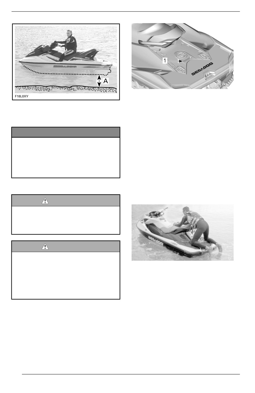
OPERATING INSTRUCTIONS
1. Rear handle
A. Maintain at least 90 cm (3 ft) underneath the
lowest rear portion of the hull when all pas-
NOTE:
sengers are aboard
If cargo is properly secured on the
boarding platform, it can be used as a
NOTICE
handle or removed and set aside in
the footwell to get access to the han-
Startiing the engine or riidiing the
dle. Always properly secure the cargo
watercraft iin shalllower water may
before riding.
damage the iimpelller or other jjet
pump components.Stay on center
2. With the other hand on the board-
of the step.Only one person at a
ing platform, lift your body until you
tiime on the ladder.
can lay one knee on the boarding
platform.
Boarding iin Deep Water
3. Lay the other knee on the boarding
platform.
WARNING
Keep llimbs away from propulsiion
system or iintake grate.Never use
propulsion systems a supporting
poiint to board the watercraft.
WARNING
Ask iinexperienced riiders to prac-
tiice how to board the watercraft
TYPICAL
cllose to shore (alll methods ex-
4. Take hold the seat or the seat
pllained here) before venturing in-
strap to help maintain your bal-
to deep water, especiallly when
ance and step forward onto the
cargo is installled aboard on the
footboards on either side of the
rear platform.
seat.
Operator Allone Wiithout a Boarding
Ladder
1. Using one hand, grab the rear
handle.
84
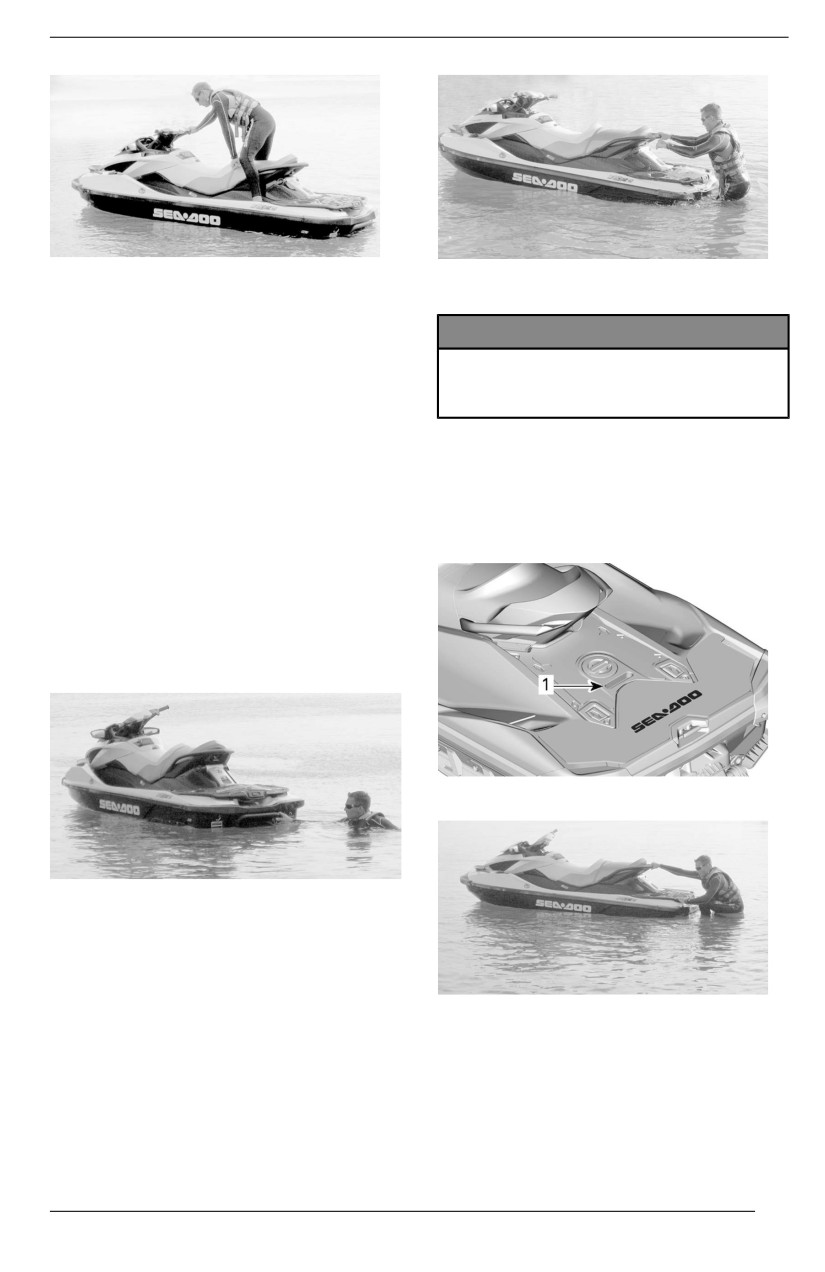
OPERATING INSTRUCTIONS
TYPICAL
TYPICAL
5. Sit astride the seat.
NOTICE
It is possible to swim toward side,
– Stay on center of the ladder.
use passenger handhold and/or
– Onlly one person at a tiime on
seat strap to lift yourself aboard.
the lladder.
NOTE:
The side boarding method is not rec-
4. Reach forward with one hand and
ommended as a first try boarding
take hold of the molded handles
method. It must only be used in last
on the sides of the back seat or the
resort as it is not the easiest method
rear handle, then stand on the
to board a watercraft.
boarding ladder.
Operator Alone With a Boardiing
Ladder
1. Swim to the rear of the watercraft.
2. Using one hand, lower the board-
ing ladder.
1. Rear handle
TYPICAL
3. Using the other hand, take hold of
the edge of the boarding platform,
then pull yourself up so that you
can knee onto the boarding ladder.
TYPICAL
85
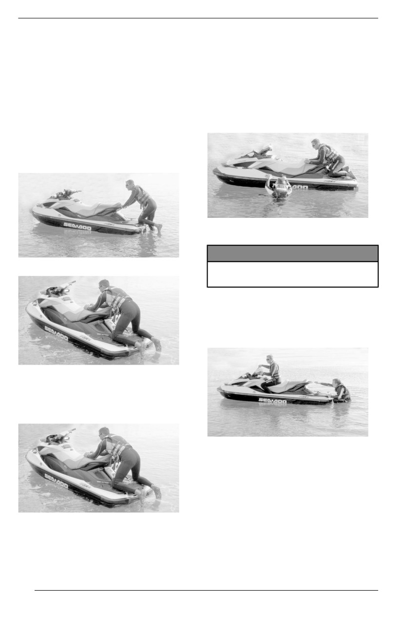
OPERATING INSTRUCTIONS
Operator wiith a Passenger
1. The operator climbs on the water-
NOTE:
craft in the same way as explained
If cargo is properly secured on the
previously.
boarding platform, it can be used as a
handle or removed and set aside in
In choppy water, while in the
the footwell to get access to the han-
water, the passenger may hold the
dle. Always properly secure the cargo
watercraft steady to help the oper-
before riding.
ator climb aboard.
5. With both hands on the handle be-
hind the seat, step up onto the
boarding platform.
TYPICAL
NOTICE
TYPICAL
Stay on center of the step.Onlly
one person at a tiime on the step.
2. The passenger then climbs onto
the watercraft while the operator
maintains balance by sitting as
close as possible to the console.
TYPICAL
6. Take hold of the seat strap to help
maintain your balance and step
forward onto the footboards on ei-
ther side of the seat.
TYPICAL - MODEL WITH BOARDING LAD-
DER SHOWN
TYPICAL
7. Sit astride the seat.
86
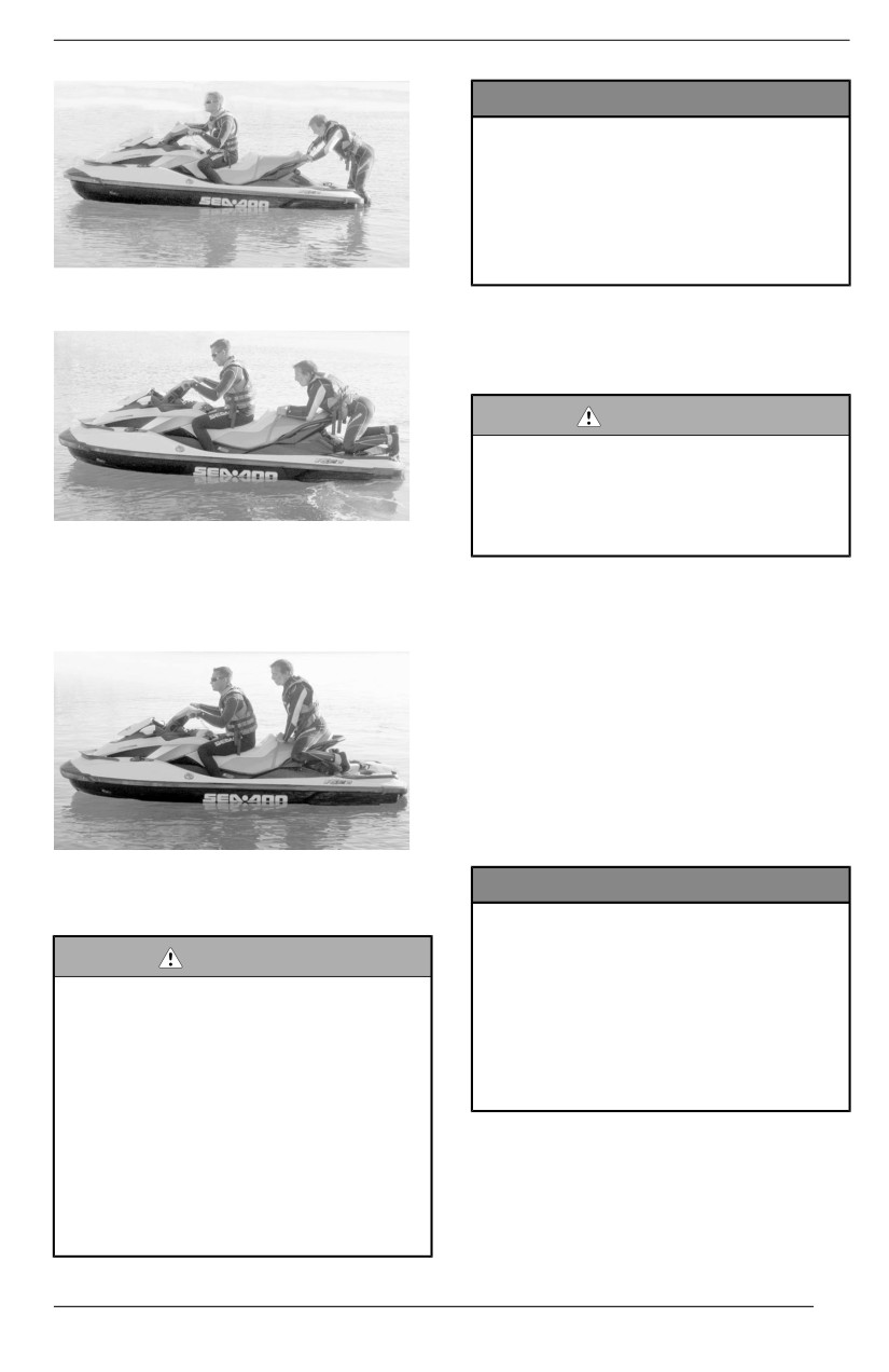
OPERATING INSTRUCTIONS
NOTICE
Ensure there iis at least 90 cm (3
ft) of water under the llowest rear
portion of the hulll when alll pas-
sengers are aboard prior to start-
i
ing the engiine. Otherwiise damage
to the propulsion system compo-
nents may occur.
TYPICAL
1. Attach the tether cord clip to your
PFD or to the wrist (wrist strap
required).
WARNING
The tether cord shalll always be
attached to the operators person-
all flotation deviice or to the wrist
(wriist strap required) when start-
TYPICAL
i
ing or operatiing the watercraft.
3. The passenger must sit astride the
seat and maintain a firm grip of a
2. Firmly grip handlebar with your left
handhold or the waist of the per-
hand and place both feet on the
son in front of them.
footboards.
3. Press the engine START/STOP
button to wake up the electrical
system.
4. As the information center cycles
through its self test function, install
the tether cord on the engine cut--
off switch.
5. Depress the START/STOP button
to start the engine.
TYPICAL
NOTICE
Starting the Engine
In the event the engine does not
start riight away, do not hold
WARNING
START/STOP button more than
Before startiing the engiine, the op-
10 seconds to avoiid starter over-
erator and passenger(s) should
heating. A rest period should be
always:
observed between the cranking
cyclles to alllow the starter to cooll
– Be properly seated on the
down. Refer to Troublleshooting
watercraft.
sectiion.
– Have a firm grip on a handholld
or hold on to the waiist of the
person iin front of them.
6. Release engine START/STOP
– Wear appropriate protectiive
button after engine is started.
cllothing iinclludiing a PFD ap-
proved by local authoriitiies and
a wet suit bottom.
87
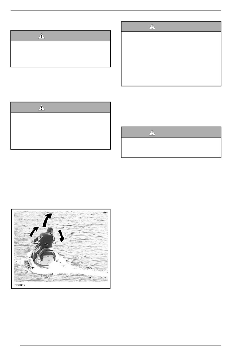
OPERATING INSTRUCTIONS
Shutting Off the Engine
WARNING
WARNING
Throttlle must be appliied and han-
dlebar turned to change the diirec-
To maintaiin watercraft diirectiional
tion of the watercraft. Steering
controll, the engiine shalll be run-
effiiciiency wiilll differ dependiing on
niing untill the watercraft iis
the amount of throttle appllied, the
stopped.
number of passengers, the load,
the water condiitions and the envi-
1. Press the engine START/STOP
ronmental factors such as the
button, or
wind.
2. Pull off the tether cord cap from
the engine cut-off switch.
Unlike a car, a watercraft needs some
throttle to turn. Practice in a safe area
WARNING
applying the throttle and turning away
from an imaginary object. This is a
Never lleave the tether cord on the
good collision avoidance technique.
engine cut-off switch when diisem-
barking watercraft to prevent
theft, acciidental engine starting,
WARNING
and to avoid unauthorized use by
Directiionall controll is reduced
chilldren or others.
when the throttlle iis released and
lost when the engiine is off.
If the engine is shut off using the
START/STOP button and the teth-
The watercraft behaves differently
er cord is left on the engine cut-off
with a passenger and requires greater
switch, the electrical power will
skill. The passenger (s) shall grip the
shut off after approximately 60 mi-
seat strap, the molded grab handle, or
nutes to prevent battery discharge.
the waist of the person ahead of them.
Reduce speed and avoid sharp turns.
Steering the Watercraft
Avoid choppy water conditions when
carrying a passenger.
O.T.A.S.TM System (If Equipped)
(Off-Throttlle Assiisted Steeriing)
The O. T. A. S. (Off-Throttle Assisted
Steering) system provides additional
maneuverability
in
off-throttle
situations.
If the driver releases the throttle to idle
when initiating a full turn, the O.T.A.S.
system will be electronically activated,
and will slightly increase engine speed
to allow completion of the turn.
Turning the handlebar pivots the jet
When the handlebar is brought back
pump nozzle which controls the water-
towards its center position, the throttle
craft direction. Turning the handlebar
reverts to idle.
to the right will turn the watercraft to
the right and inversely. You need to
apply throttle to steer.
88
OPERATING INSTRUCTIONS
We recommend that you familiarize
From forward thrust position, tap the
yourself with this feature during your
iBR lever. The gate will move to
first ride.
neutral.
If braking or reverse is used, the iBR
Tight Turns and Other Special
gate will move to the neutral position
Maneuvers
when the iBR lever is released, if
Any tight turns or special maneuvers
throttle is not applied.
that will cause the air inlet openings to
be kept under water for a prolonged
NOTE:
time, water will seep into the bilge.
The throttle lever must be fully re-
leased for the iBR gate to move to the
Combustion engines need air to oper-
neutral position when the iBR lever is
ate; consequently this watercraft can-
released.
not be totally watertight.
If the engine is stopped in forward or
NOTICE
reverse, the iBR gate will move to the
If the air iinlet openings are kept
neutral position on engine shutdown.
under water, such as turning con-
stantly in tiight circles, pllungiing
Adjjusting the Neutrall Position of
the bow through waves, or capsiz-
the iBR
iing the watercraft, water may
When in NEUTRAL, if the watercraft
seep iinto the biilge, whiich may
creeps forward or backward, the iBR
cause severe damage to iinternal
system may be trimmed.
parts of the engiine. Refer to the
Warranty sectiion contaiined iin thiis
NOTE:
guide.
Movement of the watercraft when op-
erating in neutral may be due to wind
Models Without iBR
or water current.
On these models, as soon as the en-
1.
Hold down the VTS up or down
gine runs, the PWC is always moving
button for
0.5
Sec to enter the
forward.
Neutrall Adjust mode.
On these models, there is no braking
The message Neutral Adjust will
system available. Be careful.
be displayed.
2.
Adjust the Neutral position:
Shifting into Neutral
- Watercraft is moving forwards -
press the VTS DOWN button.
WARNING
- Watercraft is reversing - press
The drive shaft and impelller are
the VTS UP button.
always turning when the engine is
runniing, even when the iBR gate
Adjust to achieve no movement
i
is set to the neutrall posiitiion. Keep
when the engine is at idle.
away from the propullsion system
of the watercraft.
When the watercraft is first started,
the iBR system automatically sets the
iBR gate to the neutral position by
default.
89
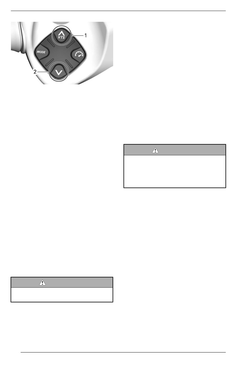
OPERATING INSTRUCTIONS
the amount of reverse thrust
produced.
By modulating both the iBR and throt-
tle levers simultaneously, reverse
thrust can be more precisely con-
trolled. Too much RPM will create
water turbulence and reduce reverse
efficiency.
NOTE:
1. Bow up
Engine power will be reduced to idle
2. Bow down
whenever the iBR lever position is
changed.
3. Press OK button or wait 25 sec to
exit the Neutral Adjjust mode.
Available engine power is limited in re-
verse mode, which limits reverse
Shifting into Forward
speed. However, speeds above 14
km/h (9 MPH) may be obtained in re-
From neutral, tap on the throttle lever
verse depending on conditions.
to shift into forward. The gate will
move to forward thrust position and
the watercraft will accelerate forward.
WARNING
Only use reverse at sllow speed
From reverse, release the iBR lever
and for the shortest tiime possible.
while applying throttle moderately.
Allways ensure the path behiind is
clear of objects, obstaclles and
From braking, simultaneously pull in
peoplle.
the throttle lever while releasing the
iBR lever. The watercraft will acceler-
ate forward after a short delay.
When operating in reverse, turn the
handlebar in the opposite direction
Shifting into Reverse
that you want to move the rear of the
watercraft.
Reverse can only be engaged be-
tween idle speed and the threshold
For example, to steer the rear of the
forward speed of 14 km/h (9 MPH).
watercraft to port (left), turn the han-
dlebar to starboard (right).
1. Pull in the iBR lever at least 25%
of the lever travel.
2. Release the iBR lever to end re-
verse operation.
3. Apply enough throttle to stop rear-
ward movement.
WARNING
The brake functiion has no effect
when travellling in reverse.
When operating the iBR lever in re-
verse mode, the throttle lever can be
used to control engine RPM, and thus
90
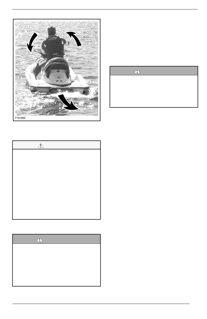
OPERATING INSTRUCTIONS
The braking function can only be en-
gaged during forward operation at or
above the threshold speed of 14 km/h
(9 MPH).
Braking is engaged and controlled
when the iBR lever on the LH handle-
bar is pulled in at least
25% of its
travel.
WARNING
Brakiing shoulld be practiced iin
open waters and at graduallly iin-
creasiing speeds iin order to be-
come fullly familliar with the
controlls and watercraft handlling
characteristics.
When iBR lever is applied, the throttle
lever command is overridden and en-
TYPICAL
- STEERING DIRECTION
RE-
gine throttle control is now dependant
VERSED WHEN BACKING
on the iBR lever position. Braking can
thus be modulated by using only the
iBR lever.
CAUTION
Watercraft deceleration is proportional
Steering directiion in reverse
to the braking force. The more the iBR
thrust is opposite of forward
lever is pulled in, the greater the brak-
thrust. To steer the stern to port
ing force applied. The deceleration is
(lleft) in reverse, turn the handle-
also related to the total weight on the
bar to starboard (right). To steer
watercraft. A fully loaded watercraft
the stern to starboard (right), turn
(cargo and passengers) will not decel-
the handlebar to port (left). Re-
erate as fast as it could without this
verse thrust operation should be
load.
practiiced in open waters iin order
to become fullly familliar with the
controls and watercraft handliing
characteriistiics before operatiing iin
close quarters.
Braking
WARNING
The engiine must be running to be
able to use the brake.The brake iis
only appllicable when operating iin
forward movement, it has no ef-
fect on rearward vellociity.The
brake cannot prevent your water-
craft from drifting due to current or
wind.
91
OPERATING INSTRUCTIONS
proportional to the throttle lever
position.
NOTE:
Be careful to gradually actuate the
WARNING
iBR lever to adjust intensity of the
braking force and simultaneously re-
If forward accelleration iis not de-
lease the throttle lever.
sired when the brake llever iis re-
leased, release the throttle lever.
CAUTION
When braking, riders must brace
WARNING
themsellves against the decelera-
It iis important to inform other op-
tiion force to prevent from moviing
erators who iintend to folllow iin a
forward on the watercraft and los-
convoy formation of the braking
iing ballance. The operator shoulld
and maneuveriing capabiiliity of
allways keep both hands on the
your vehiicle and that a greater
handlebars, and alll passengers
distance should be maintained.
should maintain a firm griip on
their seat and/or the hand raill.
Brakiing in a Turn
Throttle must be applied for turning to
WARNING
ensure directional control. However
Stopping distance willl vary de-
braking can be initiated during a turn
pending on initiall speed, load,
using the iBR lever as previously de-
wiind, number of riders, water con-
scribed. Get ready to maintain your
diitions, and the amount of braking
balance while the wake is crossing
power commanded by the opera-
your watercraft.
tor. Allways adjjust your riidiing style
accordiinglly.
CAUTION
As the watercraft slows to a stop
When the watercraft slows to less
whiile brakiing in a turn, the wake
than 14 km/h (9 MPH), braking mode
created by the watercraft will
ends and reverse mode is engaged.
catch up and tend to push the
Release the iBR lever once the water-
watercraft siideways. Be prepared
craft is stopped. Otherwise, a rear-
to maiintaiin ballance as the wake
ward movement will be initiated.
crossed the watercraft.
CAUTION
As the watercraft slows to a stop,
the wake created by the water-
craft wiilll catch up and tend to
push the watercraft forward. En-
sure there are no obstacles or
bathers iin the directiion of travell.
If the throttle lever is still pulled in
when releasing the iBR lever, the
watercraft will accelerate forward after
a short delay. Acceleration will be
92
OPERATING INSTRUCTIONS
General Operating
WARNING
Recommendations
When crossiing wakes or waves,
NOTICE
sllow down. Operator and passen-
ger(s) should brace themsellves
Combustion engiines need aiir to
and adopt a semii-standing posii-
operate; consequentlly this water-
tiion to hellp absorb the bumps.Do
craft cannot be totallly watertight.
not jump wakes or waves - jjump-
Any maneuvers such as turniing
iing can cause injjuriies such as
constantly iin tiight circlles, plung-
back or spinal iinjury (parallysiis).
iing the bow through waves, or
capsiziing the watercraft, that
cause the aiir inlet openiings to be
Stopping/Dockiing
under water may cause severe
When the throttle is released, the
engiine probllems due to water iin-
watercraft is slowed by water drag
gestiion. Refer to How to Steer the
against the hull. The stopping dis-
Watercraft iin the Operating In-
tance will vary depending on the
structions sectiion and the War-
watercraft size, weight, speed, water
ranty section contained in this
surface condition, presence and direc-
Operator’s Guide.
tion of wind and current.
The iBR system can also be used for
Rough Water or Poor Visiibiiliity
slowing down or for stopping more
Operation
quickly, and for increasing maneuver-
Avoid operation in these conditions. If
ability especially when docking.
you must do so, proceed with caution
using minimum speed.
The operator should practice in open
waters at various speeds to become
Crossing Wakes or Waves
familiarized with the stopping distan-
ces under different conditions. Stop-
1. The operator must grip the handle-
ping using the iBR system in a straight
bar firmly and keep both feet on
line and in a turn should be practiced
the footboards.
extensively to become familiar with
2. The passenger must grip the
the handling characteristics of the
handholds with both hands and
watercraft under partial or full braking
keep both feet on the footboards.
conditions.
3. Reduce speed.
4. Always be prepared to steer and
maintain
your balance as
WARNING
necessary.
5. When going over waves, raise
Always practiice brakiing in open
your body slightly off the seat to
waters ensuriing there are no
absorb the shocks with your legs.
watercrafts or boats in your iimme-
6. When crossing wakes, always
diiate viciniity, especiallly astern.
keep a safe distance from water-
Other users of the waterways may
craft ahead.
not be ablle to maneuver or stop in
tiime to avoid you shoulld you un-
expectedlly come to a fulll stop iin
front of them.
93
OPERATING INSTRUCTIONS
lowest rear portion of the hull. Then
pull the watercraft to the beach.
WARNING
It is iimportant to iinform other op-
NOTICE
erators who intend to folllow in a
Riding the watercraft iin shalllow
convoy formatiion of the braking
water may result iin damage to the
and maneuvering capabillity of
impelller, iBR components, or oth-
your vehiiclle and that a greater
er jet pump components. Always
diistance shoulld be maiintaiined.
shut off the engine before water iis
less than 90 cm (3 ft) deep and
The operator should also practice
never use reverse or brakiing.
docking with an imaginary dock using
the various controls available (iBR lev-
er and throttle lever).
Release the throttle at a sufficient dis-
tance before the expected landing
area.
Reduce speed to idle.
Maneuver using a combination of the
iBR lever and throttle lever, shifting to
neutral, reverse, or forward as
required.
Remember that when operating in re-
verse, steering direction is reversed.
Turning the handlebars to the left will
move the stern to the right when back-
ing up, and vice-versa.
WARNING
Diirectional controll is reduced
when the throttle iis relleased and
l
lost when engine is off. Steering
diirection iis reversed when operat-
i
ing the watercraft in reverse.
Beaching
NOTICE
It is not recommended to run the
watercraft to the beach.
Drive slowly towards the beach and
shut off the engine before the water is
less than 90 cm (3 ft) deep under the
94
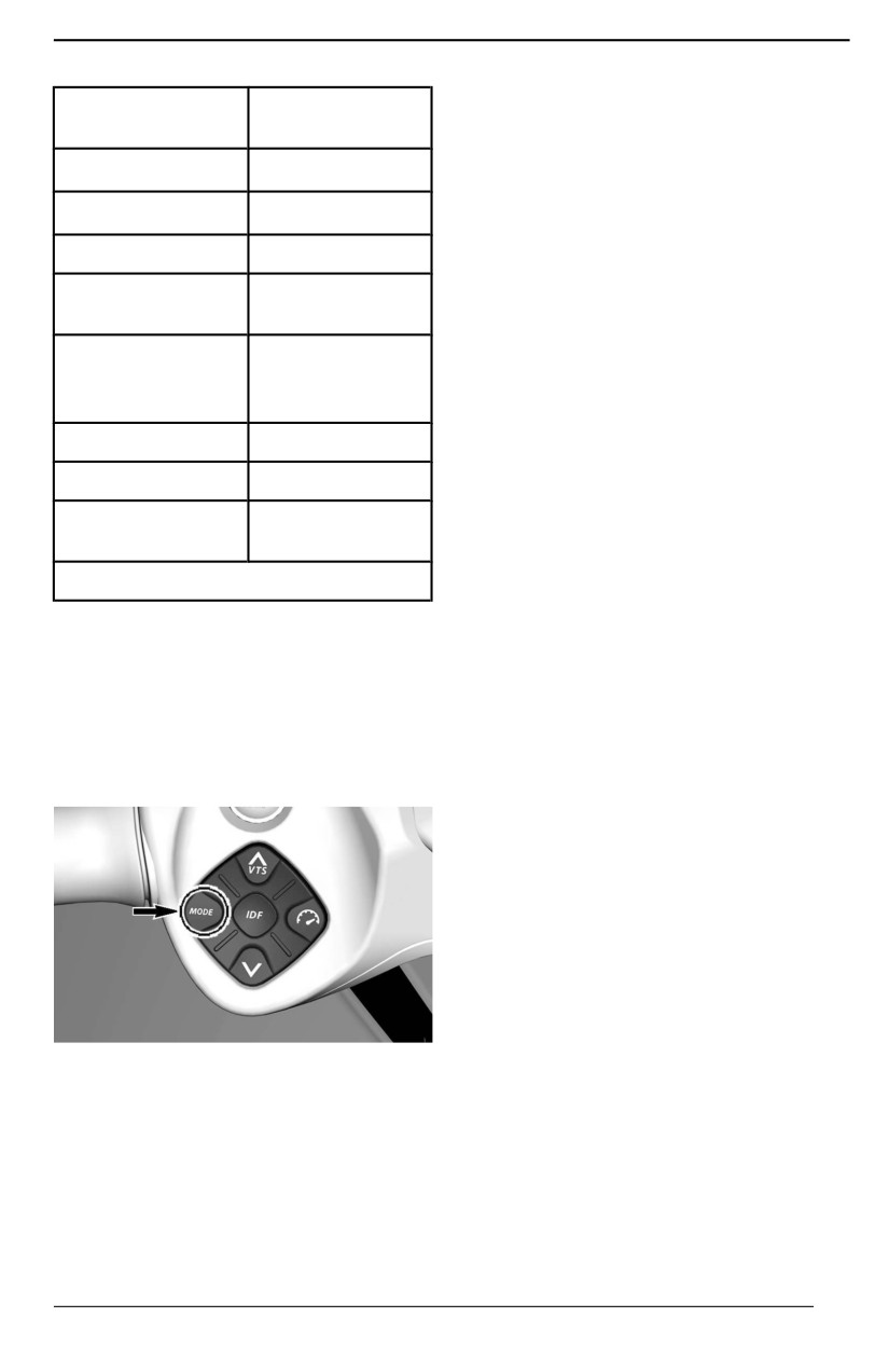
OPERATING MODES
The icon ECO +OFF appears in the
Operating mode
GTX PRO
display when this mode is selected.
avaiilable
Touring mode
X
Sport Mode
SPORT MODE provides for instant
Sport mode
X
throttle response and more rapid ac-
celerations than DEFAULT riding
ECO mode
N/A
MODE.
Speed limiter
N/A
Once activated, SPORT MODE will
mode
remain active until it is deactivated by
the operator, or the engine is shut
Slow speed
down whereby it defaults back to DE-
mode (Trolling
N/A
FAULT riding MODE.
mode)
Ski mode
N/A
Activating Sport Mode
To activate the Sport mode, press
Launch control
N/A
once on the MODE button while in
DEFAULT riding mode. The sport icon
Learning key
X
will start to flash and a safety mes-
mode
sage will scroll. For safety reason, fol-
X = Indicates a standard feature
low the instruction in the safety
message to activate the sport mode.
To change the operating mode;
Once activated, the SPORT icon will
turn ON.
1. Press MODE button,
2. Acknowledge the safety message
Deactivatiing Sport Mode
by pressing and holding MODE
A single press on MODE button will
button will get the SPORT mode,
take you to the ECO mode.
3. Pressing MODE button again will
activate the ECO mode.
ECO Mode
(Fuel Economy Mode)
ECO mode provides a smoother throt-
tle application and increased fuel
economy.
Learning Key Mode (if
equipped)
The learning key provides a mode of
operation whereby engine power and
speed is limited.
TYPICAL
There are 5 speed settings available.
Touring Mode
By default, the speed setting is no 1.
By default, the watercraft is set to this
riding mode of operation when
Refer to
4.5'' Digital Display for
started.
adjustment.
It is also called Normal riding mode.
95
SPECIAL PROCEDURES
Jet Pump Water Intake and
Modells equiipped wiith the iDF
system
Impeller Cleaning
If the watercraft is equipped with the
WARNING
iDF system, use it now. Refer to How
Keep away from intake grate
to Use the intelligent Debris Free
whille engiine iis running. Items
Pump System in Operating Instruc-
such as llong hair, loose cllothing
tions section.
or personall fllotation deviice straps
Modells without iiDF system
can become entangled in moving
parts.
1. Rock the watercraft several times.
Most of the time, this will remove
Weeds, shells or debris can get
the blockage.
caught on the intake grate, drive shaft
2. Start engine and make sure water-
and/or impeller. A clogged water in-
craft operates properly.
take may cause troubles such as:
If the aforementioned method does
- Cavitatiion: Engine speed is high
not work:
but watercraft moves slowly due to
3. With engine running and before
reduced jet thrust, jet pump com-
applying throttle, pull the iBR lever
ponents may be damaged.
in to select reverse operation.
- Overheatiing: Since the jet pump
4. Vary throttle quickly several times.
operation controls the flow of water
5. Repeat procedure if necessary.
to cool the exhaust system, a
clogged intake will cause the en-
If system is still blocked, move the
gine to overheat and damage en-
watercraft out of the water for
gine internal components.
cleaning. Refer to On-Beach
Water Cleaning.
A weed clogged area can be cleaned
as follows:
On-Beach Water Clleaniing
WARNING
WARNING
If it iis necessary to reach iin to re-
The tether cord MUST BE RE-
move any foreign objject caught in
MOVED from the engine cut-off
the propullsiion system, the tether
swiitch to prevent acciidental en-
cord MUST BE REMOVED from
gine starting before cleaniing the
the engiine cut-off swiitch.
jet pump area.
In-Water Clleaniing
1. Place a cardboard or a carpet be-
side the watercraft to prevent
NOTICE
scratching when turning the water-
Ensure there iis at least 90 cm (3
craft for cleaning.
ft) of water under the llowest rear
2. Rotate the watercraft to any side
portion of the hulll when all pas-
for cleaning.
sengers are aboard prior to start-
i
ing the engiine. Otherwiise damage
to the propulsion system compo-
nents may occur.
96
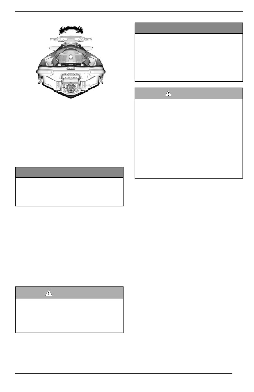
SPECIAL PROCEDURES
NOTICE
An objject or tooll caught iin the iiBR
system when using the iiBR over-
riide functiion may cause damage
to the iiBR components. Remove
alll riigid foreiign objjects that may
obstruct the iiBR gate travel before
moviing iit.
WARNING
TYPICAL
If it iis necessary to reach iin to re-
3. If equipped, move the iBR to the
move any foreign objject caught in
forward position. Refer to iBR
the propulsiion system, striictlly ob-
Override Function for detailed
serve the folllowing before
instructions.
proceediing:
4. Clean the water intake area.
– Remove tether cord from the
engiine cut-off swiitch.
If the system is still clogged, refer
– Waiit at lleast 5 minutes.
to an authorized Sea-Doo dealer
– Do not press on START/STOP
for servicing.
button. Should the START /
STOP button be pressed, wait
NOTICE
another 5 minutes.
Inspect water iintake grate for
damage. Refer to an authoriized
Activating iBR Override Function
Sea-Doo dealer for repaiir as
1. Power up the electrical system by
necessary.
pressing the START/STOP button.
2. Install the tether cord on the en-
iBR Override Function
gine cut-off switch.
When the iBR override function is acti-
NOTE: The tether cord must be in-
vated, it allows the user to electrically
stalled to ensure the information cen-
move the iBR gate and nozzle through
ter will not shut off all indications after
its full range of motion using the VTS
its self test function. Electrical power
control button.
will stay on for approximately 1 hour.
NOTE:
3. Pull in and hold the iBR lever for
The iBR override function is only avail-
the entire procedure.
able when the engine is not running.
WARNING
When moving the iiBR gate using
the iiBR overriide functiion, ensure
no one iis near the rear of the
watercraft. Movement of the gate
may squeeze fingers.
97
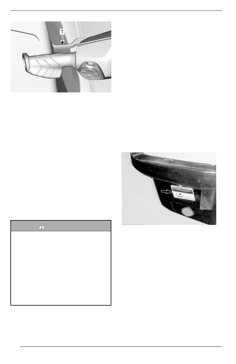
SPECIAL PROCEDURES
Capsized Watercraft
The watercraft is designed so that it
should not turn over easily. Two spon-
sons mounted on the side of the hull
assist watercraft stability. If it turns
over, it will remain capsized.
To turn the watercraft upright, ensure
the engine is off and the D.E.S.S. key
is NOT on its post, then grab the inlet
grate, step on a side bumper rail and
use your weight to rotate the water-
1.
iBR lever pulled and held
craft towards you.
4.
When the IBR OVERRIDE
-
NOTE:
PRESS MODE BUTTON mes-
A label on the stern near the flushing
sage appears in the multifunction
connector provides instructions on
gauge, press the MODE button.
how to turn the watercraft right side
up. The label is upside down so that it
When the function is activated, a
can be read when the watercraft is
ON message will be shown.
overturned.
5.
While still holding the iBR lever in,
press the VTS UP/DOWN button
to move the iBR gate to the de-
sired position. Ensure the VTS in-
dication in the multifunction gauge
changes with the iBR gate move-
ment. If the iBR gate moves up-
wards, the indication moves
upwards.
6.
Release the iBR lever.
7.
Remove the tether cord from the
engine cut-off switch.
WARNING
TYPICAL
If it iis necessary to reach iin to re-
The engine features a Tip-Over Pro-
move any foreign objject caught in
tection System (T. O. P. S.™). When
the propullsiion system, striictlly ob-
the watercraft tips over, the engine is
serve the folllowing before
automatically stopped.
proceediing:
– Remove tether cord from the
When the watercraft is returned to its
engiine cut-off swiitch.
normal operating position, the engine
– Waiit at lleast 5 minutes.
can be started normally.
– Do not press on START/STOP
button. Should the START /
STOP button be pressed, wait
another 5 minutes.
98
SPECIAL PROCEDURES
Water-Flooded Engine
NOTICE
When the watercraft has been
NOTICE
turned over 5 miinutes, do not at-
Never try to crank or start the en-
tempt to crank the engine to avoid
giine. Water trapped in iintake
water iingestiion that would dam-
maniifolld would flow towards the
age the engiine. See an author-
engine and possiibly cause severe
i
ized Sea-Doo dealer as soon as
engine damage.
possiblle.
Bring the watercraft to an authorized
NOTICE
Sea-Doo dealer as soon as possible
If the engiine does not crank, do
to have it serviced.
not attempt to start it anymore.
Otherwise, the engiine could be
NOTICE
damaged. See an authoriized
Faiilure to have the engine prop-
Sea-Doo dealer as soon as
erlly serviced may cause severe
possiblle.
engine damage.
As soon as possible, check for pres-
Towing the Watercraft in
ence of water in the bilge. Drain as
Water
necessary when back to the shore.
Special precautions should be taken
Submerged Watercraft
when towing a Sea-Doo watercraft in
water.
To limit damages to the engine, per-
form the following procedure as soon
The maximum recommended towing
as possible.
speed is 8 km/h (5 MPH).
1. Drain bilge.
This will prevent the exhaust system
2. If it was submerged in salt water,
from filling with water, which may lead
spray bilge and all components
to water being injected into and filling
with fresh water using a garden
the engine. Without the engine run-
hose to stop the salt corroding
ning, there isn't any exhaust pressure
effect.
to push the water out the exhaust
outlet.
NOTICE
Never try to crank or start the en-
gine. Water trapped in intake
NOTICE
manifold woulld fllow towards the
Faiilure to folllow these instructiions
engiine and possiiblly cause severe
may resullt in damage to the en-
engiine damage.
giine. If you must tow a stranded
watercraft iin water, be sure not to
exceed the maxiimum towing
3. Bring the watercraft to an author-
speed of 8 km/h (5 MPH).
ized Sea-Doo dealer as soon as
possible to have it serviced.
NOTICE
Faiilure to have the engiine prop-
erly serviiced may cause severe
engiine damage.
99
SPECIAL PROCEDURES
NOTICE
Never tow a watercraft facing
backwards as water intrusiion may
occur.
CAUTION
A tow lline shall always be made
fast iin such a way that it can be
relleased when under lload.
100
MAINTENANCE
101
MAINTENANCE SCHEDULE
Maintenance is very important to keep your watercraft in safe operating condi-
tion. The vehicle should be serviced as per the maintenance schedule.
Proper maintenance is the owner’s responsibility. A warranty claim may be de-
nied if, among other things, the owner or operator caused the problem through
improper maintenance or use.
Perform periodic checks and follow the maintenance schedule. The maiinte-
nance schedule does not exempt the pre-ride inspection.
WARNING
Faiilure to properly maiintain the watercraft accordiing to the maiintenance
schedulle and procedures can make it unsafe to operate.
EPA Regulation - Canadian and USA Watercrafts
A repair shop or person of the owner''s choosing may maiintaiin, replace, or
repair emission control devices and systems. These instructions do not require
components or service by BRP or authorized Sea-Doo dealers.
Although an authorized Sea-Doo dealer has an in-depth technical knowledge
and tools to service your vehicle, the emission-related warranty is not conditioned
on the use of an authorized Sea-Doo dealer or any other establishment with
which BRP has a commercial relationship.
Proper maintenance is the owner’s responsibility. A warranty claim may be de-
nied if, among other things, the owner or operator caused the problem through
improper maintenance or use.
For emission-related warranty claims, BRP is limiting the diagnosis and repair of
emission-related parts to the authorized Sea-Doo dealers. For more information,
please refer to the US EPA Emissions Warranty contained in the warranty
section.
You must follow the instructions for fuel requirements in the fueling section of this
manual. Even if gasoline containing greater than ten volume percent ethanol is
readily available, the US EPA issued a prohibition against the use of gasoline
containing greater than 10 vol% ethanol that applies to this vehicle. The use of
gasoline containing greater than 10 vol% ethanol with this engine may harm the
emission control system.
102
MAINTENANCE SCHEDULE
Salt Water/ Dirty Water Usage
Whenever your watercraft is used in salt or dirty water, this type of usage re-
quires maintenance tasks to be performed between the regular yearly intervals.
These are identified as A+ in the chart below.
If you regularly ride in sallt or diirty water, follow the A+ interval and perform the
tasks outlined in the chart below.
Maintenance Schedule
Make sure to perform proper maintenance at recommended intervals as indi-
cated in the tables.
The maintenance chart indicates the items needing to be addressed based on 2
criteria, whichever happens first:
- Calendar time
- Watercraft hours.
Your driving habits determines the factors you shall adhere to. For example:
- Someone who uses their watercraft every weekend would follow the hours
reading to determine the frequency of his maintenance.
- Someone who uses their watercraft seldomly over the year or only on a few
occasions would follow the calendar tiime to determine the frequency of his
maintenance.
IMPORTANT: The following tables show the appropriate maintenance appli-
cation for the first
3 years. For subsequent years, repeat the same pattern
alternatively.
Maintenance Overview
Regular/ Salt/ Dirty
Calendar Time
Hour meter
water
Every Month
A+
1 Year
100 Hours
A
Every Month
A+
2 Years
200 Hours
A and B
Every Month
A+
3 Years
300 Hours
A
103
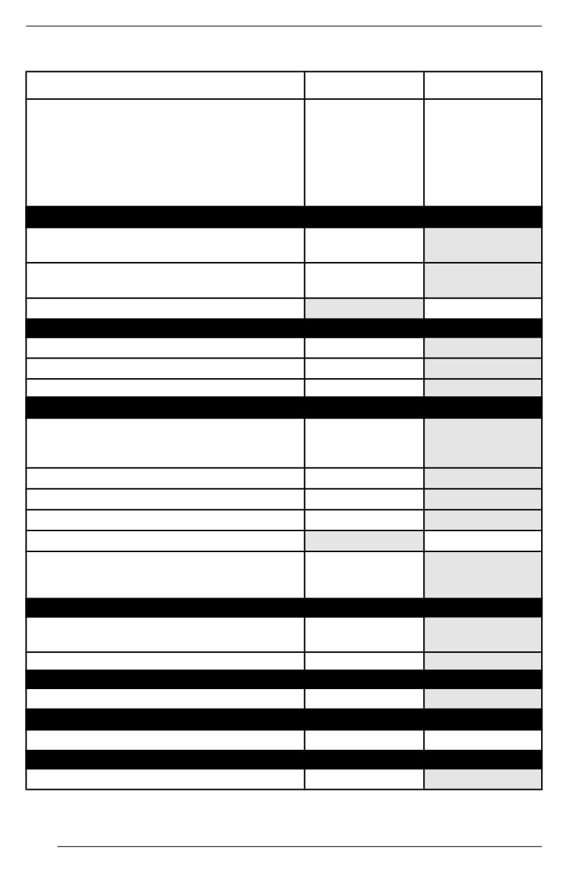
MAINTENANCE SCHEDULE
Rotax 1630 ACE Engiines
Regullar
A
B
A=Adjust
C=Clean
F=Flush
Every year
Every 2 years
I=Inspect
or
or
L=Lubricate
100 Hours
200
Hours
R=Replace
T=Torque
Air and Fuel Delivery
Air delivery components and function (ducts,
I, C
hoses, clamps)
Fuel components and function (Fuel tank cap,
I
fuel tank fixation, hose condition, leaks)
Supercharger
I
Deck and Hull
Sacrificial anode(s)
I
Body panels and hardware
I, T
Hull
I
Engine and Cooling
Engine cooling components (coolant
concentration, coolant level, hose condition,
I, A
clamps, leaks)
Engine oil and oil filter
R
Ignition components and function
I
Engine rubber mounts
I
Spark plugs
R
R
Engine coolant
Every 5 years
or 300 hour
Exhaust and Emissions
Exhaust components (gaskets, pipes, muffler
I
condition, leaks)
Exhaust
F
iBR
iBR components and function
I,
Propulsion
Propulsion components and function
I
I, L
Electrical
Battery connections and condition
I
104
MAINTENANCE SCHEDULE
Regular
A
B
A=Adjust
C=Clean
F=Flush
Every year
Every 2 years
I=Inspect
or
or
L=Lubricate
100 Hours
200 Hours
R=Replace
T=Torque
Electrical harness routing
I
Modules and applicable software updates
I
Operation of control switches and lighting
I
Steering and Controls
Steering components and function
I
Throttle operation
I
Feature
Fish finder transducer support
I, A
105

MAINTENANCE SCHEDULE
SALT/ DIRTY
A+
A
B
WATER
After each
ride in salt
A=Adjust
or
C=Clean
dirty water
Every 2
F=Flush
Every year
or
years
I=Inspect
or
monthly
or
L=Lubricate
100 Hours
when used in
200 Hours
R=Replace
salt
T=Torque
or
dirty water
Air and Fuel Delivery
Air delivery components and
I, C
function (ducts, hoses, clamps)
Fuel components and function (Fuel
tank cap, fuel tank fixation, hose
I
condition, leaks)
Supercharger
I
Deck and Hull
I
Sacrificial anode(s)
I
Every month
Body panels and hardware
I, T
Hull
I
Engine and Cooling
F
Engine compartment
After each
ride
Engine compartment metallic
L
components
Each month
Engine cooling components (coolant
concentration, coolant level, hose
I, A
condition, clamps, leaks)
Engine oil and oil filter
R
Ignition components and function
I
Engine rubber mounts
I
Spark plugs
R
R
Engine coolant
Every 5 years
or 300 hour
Exhaust and Emissions
Exhaust components (gaskets,
I
pipes, muffler condition, leaks)
106
MAINTENANCE SCHEDULE
SALT/ DIRTY
A+
A
B
WATER
After each
ride in salt
A=Adjust
or
C=Clean
dirty water
Every 2
F=Flush
Every year
or
years
I=Inspect
or
monthly
or
L=Lubricate
100 Hours
when used in
200 Hours
R=Replace
salt
T=Torque
or
dirty water
F
Exhaust
After each
F
ride
iBR
iBR components and function
I,
Propulsion
Propulsion components and function
I
I,
L
Electrical
Battery connections and condition
I
Electrical harness routing
I
Modules and applicable software
I
updates
Operation of control switches and
I
lighting
Steering and Controls
Steering components and function
I
Throttle operation
I
Steering and Controls
Steering components and function
I
Throttle operation
I
Feature
Fish finder transducer support
I, A
107
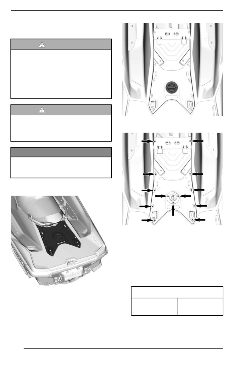
MAINTENANCE PROCEDURES
This section includes instructions for
basic maintenance procedures.
WARNING
Turn off the engiine and folllow
these maiintenance procedures
when performing maintenance. If
you do not folllow proper maiinte-
nance procedures you can be in-
j
jured by hot parts, moving parts,
ellectriciity, chemiicalls or other
hazards.
WARNING
Shoulld removal of a lockiing de-
TYPICAL
viice (e.g. llock tabs, sellf-llockiing
3. Remove the screws.
fasteners, etc.) be requiired, al-
ways replace wiith a new one.
NOTICE
Never lleave any objject, rag, tooll,
etc., iin the engiine compartment or
i
in the biilge.
Engine Service Cover
TYPICAL
4. Remove the cover.
Installliing the Engine Service Cover
1. The installation is the reverse of
the removal procedure. However,
pay attention to the following.
2. Install all screws.
3. Tighten screws to specification.
Tighteniing Torque
Removiing the Engine Service
Cover
Engine service
2.8 ± 0.2 Nm
cover screw
(25 ± 2 lbf-in)
1. Remove the seats.
2. Remove the ski/ wake pylon cover.
108
MAINTENANCE PROCEDURES
Engine Oil
Recommended Engine Oill
Rotax® engines were developed and validated using the XPS® oil.
BRP recommends the use of its XPS engine oil or an equivalent at all time.
Damage caused by the use of an oil not suitable for the engine may not be cov-
ered by the BRP Limited Warranty.
XPS Recommended Engine Oil
General purpose
5W40 synthetic blend oil
Warm temperature
10W50 synthetic oil
If the recommended XPS engine oil is not available:
Use a 4-stroke SAE synthetiic
engine oill meeting or exceeding the
following lubricant industry
specifications.
Always check the API service label
Engine Without Supercharger
certification on the oil container, it
must contain at least one of the
indicated standards.
API serviice classiificatiion SN or
JASO-MA2
Use a 4-stroke SAE motorcyclle
engine oill compatiblle wiith wet
cllutches meeting or exceeding the
following lubricant industry
specifications.
Engine Wiith Supercharger
Always check the API service label
certification on the oil container, it
must contain at least one of the
indicated standards.
API serviice classiificatiion SN or
JASO-MA2
Verifying the Engiine Oiil Levell
CAUTION
NOTICE
Many components in the engiine
compartment may be very hot. Dii-
Operating the engine with an im-
rect contact may result iin skin
proper llevell may severelly dam-
burn.
age engine.
109
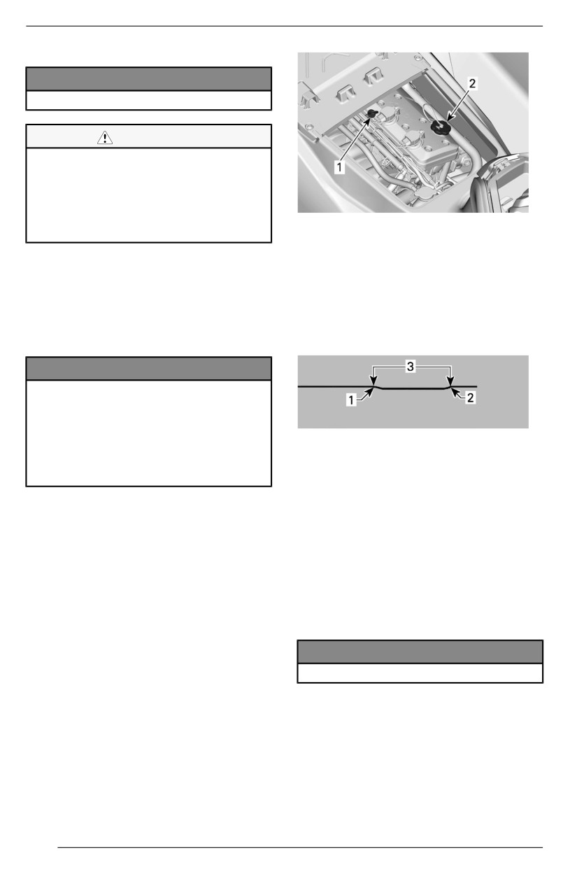
MAINTENANCE PROCEDURES
If Watercraft is Out of the Water
NOTICE
Watercraft must be levell.
CAUTION
When operating the engine whiile
the watercraft is out of water, the
heat exchanger in the ride plate
may become very hot. Avoiid any
contact wiith the ride plate as
TYPICAL
burns may occur.
1. Oil dipstick
2. Oil filler cap
1. Raise trailer tow pole, then block in
position when bumper rail is level.
11. Reinstall
dipstick,
push in
2. Install a garden hose on the ex-
completely.
haust system flushing connector.
12. Remove dipstick again and read
Refer to Exhaust System in this
oil level. It should be between the
section and follow the procedure.
FULL and ADD marks.
NOTICE
Never run engine wiithout supply-
i
ing water to the exhaust system.
Faiilure to cool exhaust system
may severely damage iit.Never run
TYPICAL
engine llonger than 2 miinutes.
1. Full
Driive lline seall has no cooliing
2. Add
when watercraft is out of water.
3. Operating range
3. Remove the seat(s).
13. Add oil to ensure the level is be-
4. Start the engine.
tween marks as required.
5. Open the water tap.
1. Remove oil cap.
6. Run the COLD engine at iidle for
30 seconds.
2. Place a funnel in valve cover
7. Close water tap.
opening.
8. Bring engine RPM to 4000-4500
3. Add a small amount of the rec-
RPM for 15 seconds.
ommended oil to reach the
9. Stop the engine abruptly by press-
proper level.
ing the start/stop button or remov-
ing the tether cord.
NOTICE
10. Wait at least 30 seconds for the oil
Do not overfilll.
to settle in the engine, then pull
dipstick out and wipe clean.
110
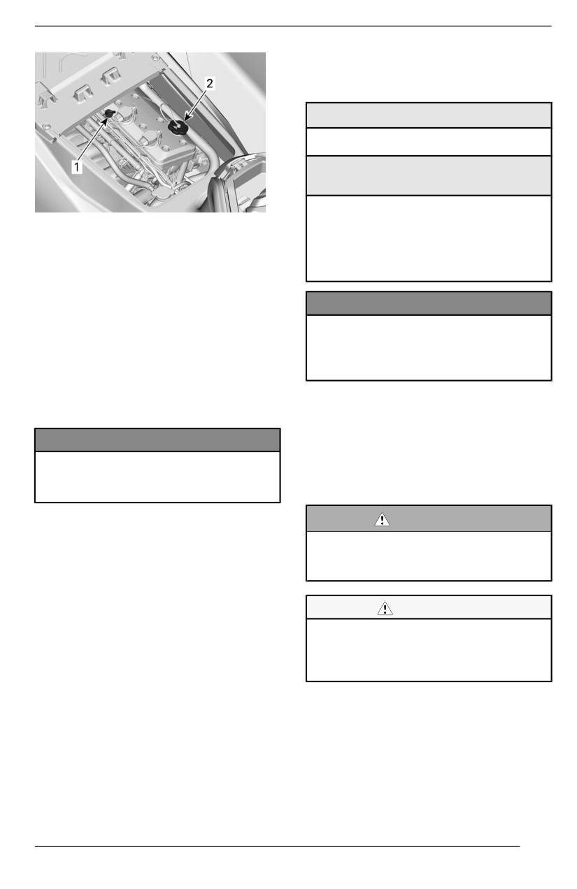
MAINTENANCE PROCEDURES
Engine Coolant
Recommended Engiine Coolant
XPS Recommended Coollant
Extended life pre-mixed coolant
If the Recommended XPS Coolant
is Not Available
Use a low silicate, extended life
TYPICAL
ethylene-glycol premixed coolant
1. Oil dipstick
(50%-50%) specifically formulated
2. Oil filler cap
for internal combustion aluminum
engines.
NOTE:
NOTICE
Every time oil is added in the engine,
the complete procedure explained in
Always use ethyllene-gllycol anti-
this section must be carried out again.
freeze contaiiniing corrosion inhibii-
Otherwise, you will obtain a false oil
tors specificallly for iinternal
level reading.
combustiion alumiinum engiines.
14. Properly reinstall oil cap and
To prevent antifreeze deterioration, al-
dipstick.
ways use the same brand and grade.
Never mix different brands or grades
NOTICE
unless cooling system is completely
Ensure that oiil fiilller cap is tighten
flushed and refilled.
properlly. Otherwiise engiine oiil can
spill out.
Engiine Coollant Levell
WARNING
Engine Oill Change and Oill Fiilter
Replacement
Check coollant llevel wiith engine
cold. Never add coolant when en-
The oil change and filter replacement
giine iis hot.
may be performed by an authorized
Sea-Doo dealer, repair shop, or per-
son of your own choosing.
CAUTION
Many components in the engiine
compartment may be very hot. Dii-
rect contact may result iin skin
burn.
1. Remove seats.
2. Locate the expansion tank cap.
111
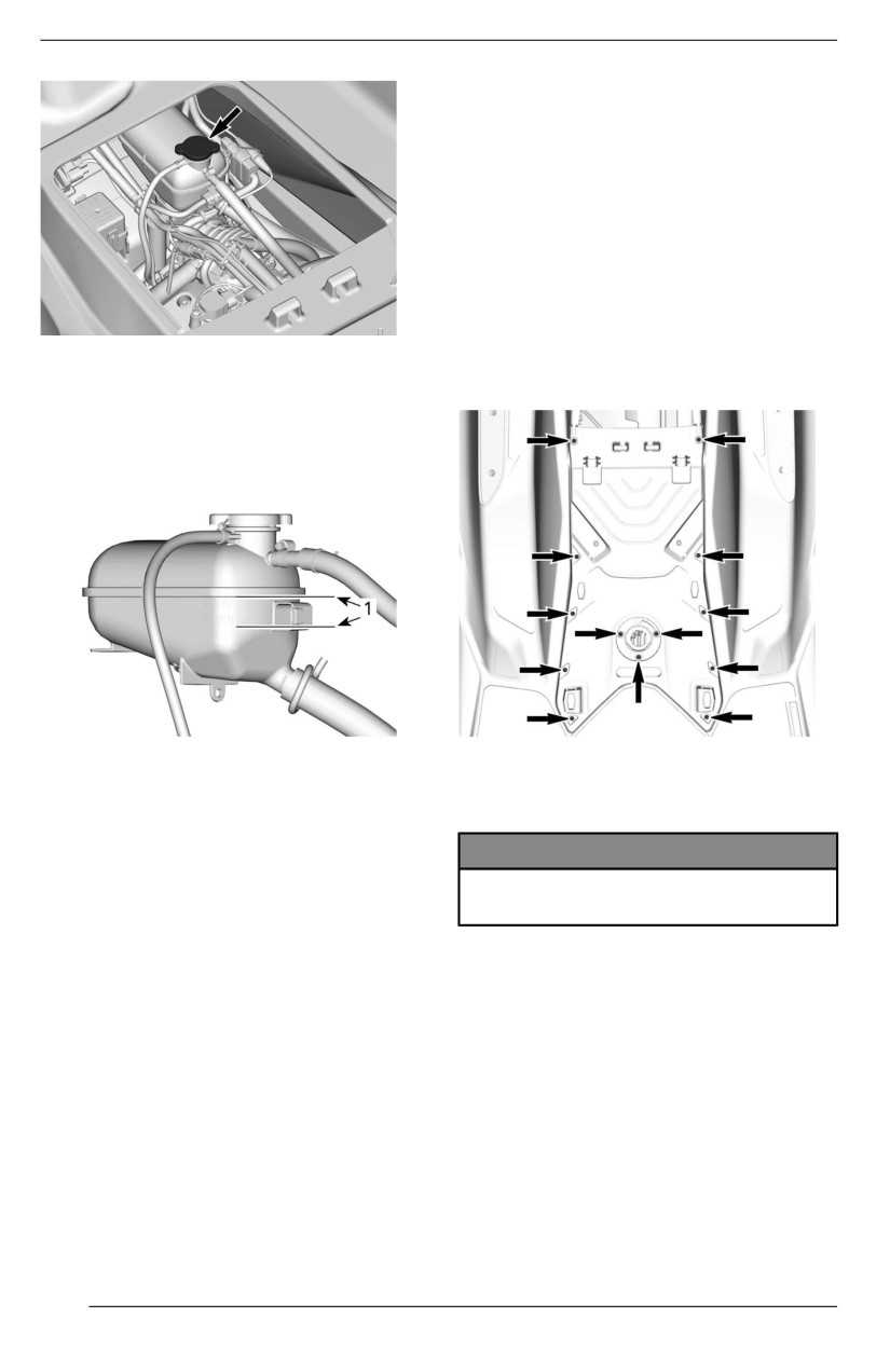
MAINTENANCE PROCEDURES
Engine Coolant Replacement
Coolant replacement should be per-
formed by an authorized Sea-Doo
dealer.
Ignition Coils
Ignitiion Coill Access
1. Remove tether cord from the en-
gine cut-off switch.
2. Remove seat(s).
TYPICAL
3. Remove engine service cover by
removing the retaining screws.
With watercraft on a level surface,
coolant level should be between
MIN. and MAX. marks on coolant
reservoir when engine is cold.
COOLANT EXPANSION TANK
1. Level between marks when engine is cold
Removing the Igniition Coiil
1. Disconnect ignition coil connector.
NOTE:
NOTICE
The watercraft is level when it is in
water. When on a trailer, raise trailer
Do not pry on igniitiion coill usiing
tow pole and block in this position
any tool.
when the lower part of the hull is level.
2. Remove ignition coil retaining
Add coolant, see Recommended
screw.
Engine Coolant for specification, to
3. Remove ignition coil from spark
adjust coolant level between
plug by rotating coil side to side as
marks as required. Use a funnel to
you pull up.
avoid spillage. Do not overfill.
3. Properly tighten the expansion
Installliing the Igniitiion Coill
tank cap. Reinstall seats.
1. Align the retaining screw hole of
NOTE:
the ignition coil with the threaded
A cooling system that frequently re-
hole on the valve cover.
quires coolant is an indication of leaks
2. Install the ignition coil on the spark
or engine problems. See an author-
plug and push it all the way down
ized Sea-Doo dealer.
until it rests on the valve cover.
112
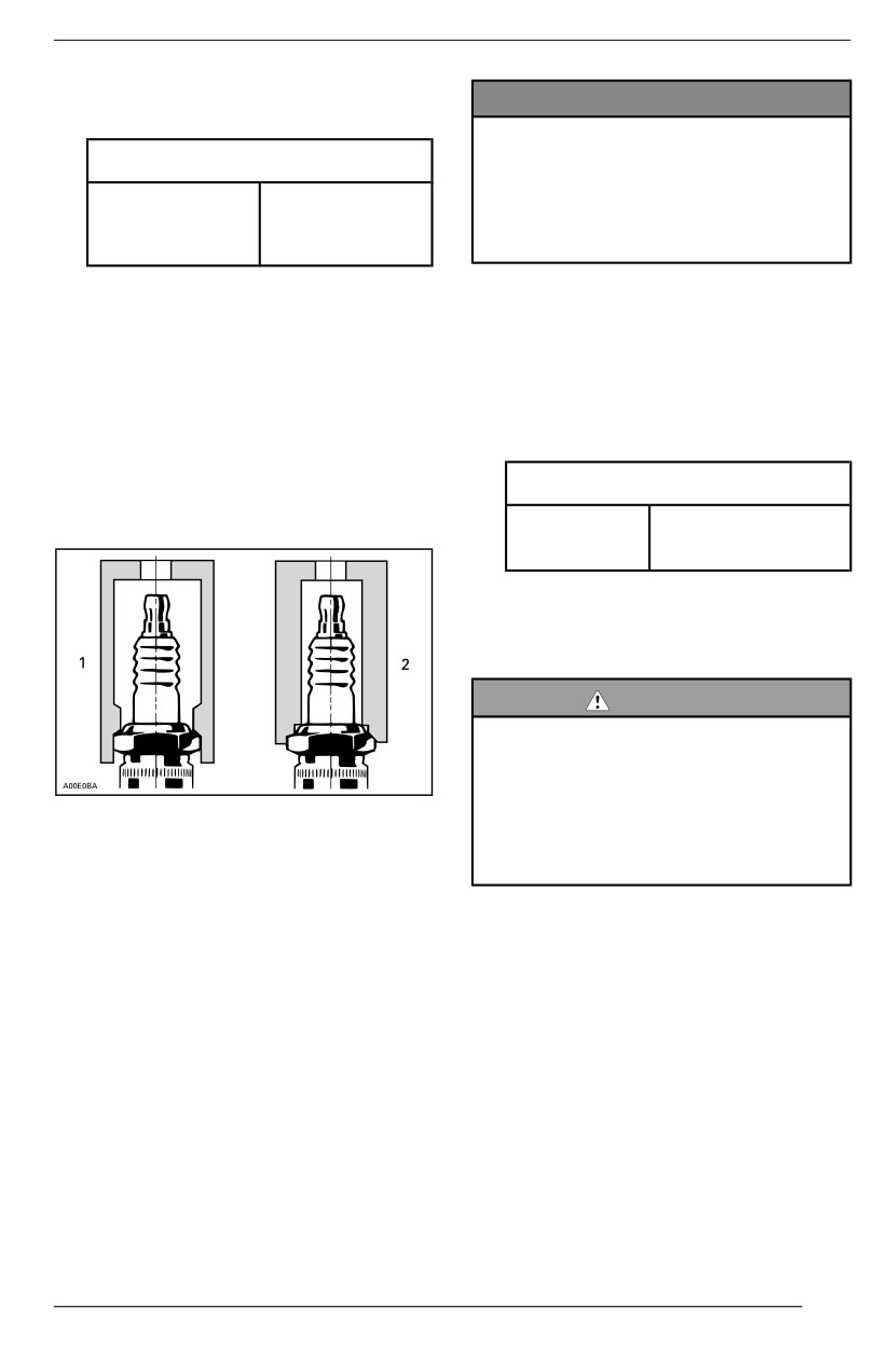
MAINTENANCE PROCEDURES
3. Install the retaining screw and
NOTICE
tighten to specification below.
Do not adjust gap on thiis type of
Tiightening Torque
spark pllug. The adjustment coulld
weaken negative electrodes
Ignition coil
which may lead to electrode
9 ± 1 Nm
retaining
breaking and severe engiine
(80 ± 9 lbf-in)
screw
damage.
4. Connect ignition coil connector.
2. Apply anti-seize lubricant on the
spark plug threads to prevent pos-
Spark Plugs
sible seizure.
3. Hand screw spark plug into cylin-
Removing the Spark Pllug
der head. Then, tighten the spark
1.
Remove the ignition coils. Refer to
plug to specification with a spark
Removing the Ignition Coil.
plug socket.
2.
Clean the spark plug and cylinder
head with compressed air.
Tightening Torque
3.
Unscrew the spark plug completely
using a spark plug socket.
18 ± 2 Nm
Spark plug
(159 ± 18 lbf-in)
4. Install the ignition coils. Refer to
Ignition Coil.
Exhaust System
DANGER
DO NOT run the engiine iindoors or
wiithout adequate ventillatiion or
permiit exhaust fumes to accumu-
l
late iin confined areas. Engiine ex-
1.
Approved socket
haust contaiins carbon monoxiide
2.
Improper socket
(CO) whiich, iif iinhalled, can cause
serious braiin damage or death.
4.
Use the ignition coil to take spark
plug out of its hole.
Fllushiing the Exhaust System
Installliing the Spark Plug
Flushing the exhaust system with
Prior to installation, ensure the contact
fresh water is essential to neutralize
surfaces of the cylinder head and
corroding effects of salt or other
spark plug are free of grime.
chemical products present in water. It
will help to remove sand, salt, shells
1. Using a wire feeler gauge, check
or other particles in water jackets and/
electrode gap as specified in Tech-
or hoses.
nical Specifications. Replace the
spark plug if not to specification.
Exhaust system flushing should be
performed when the watercraft is not
expected to be used further the same
day or when the watercraft is stored
for any extended time.
113
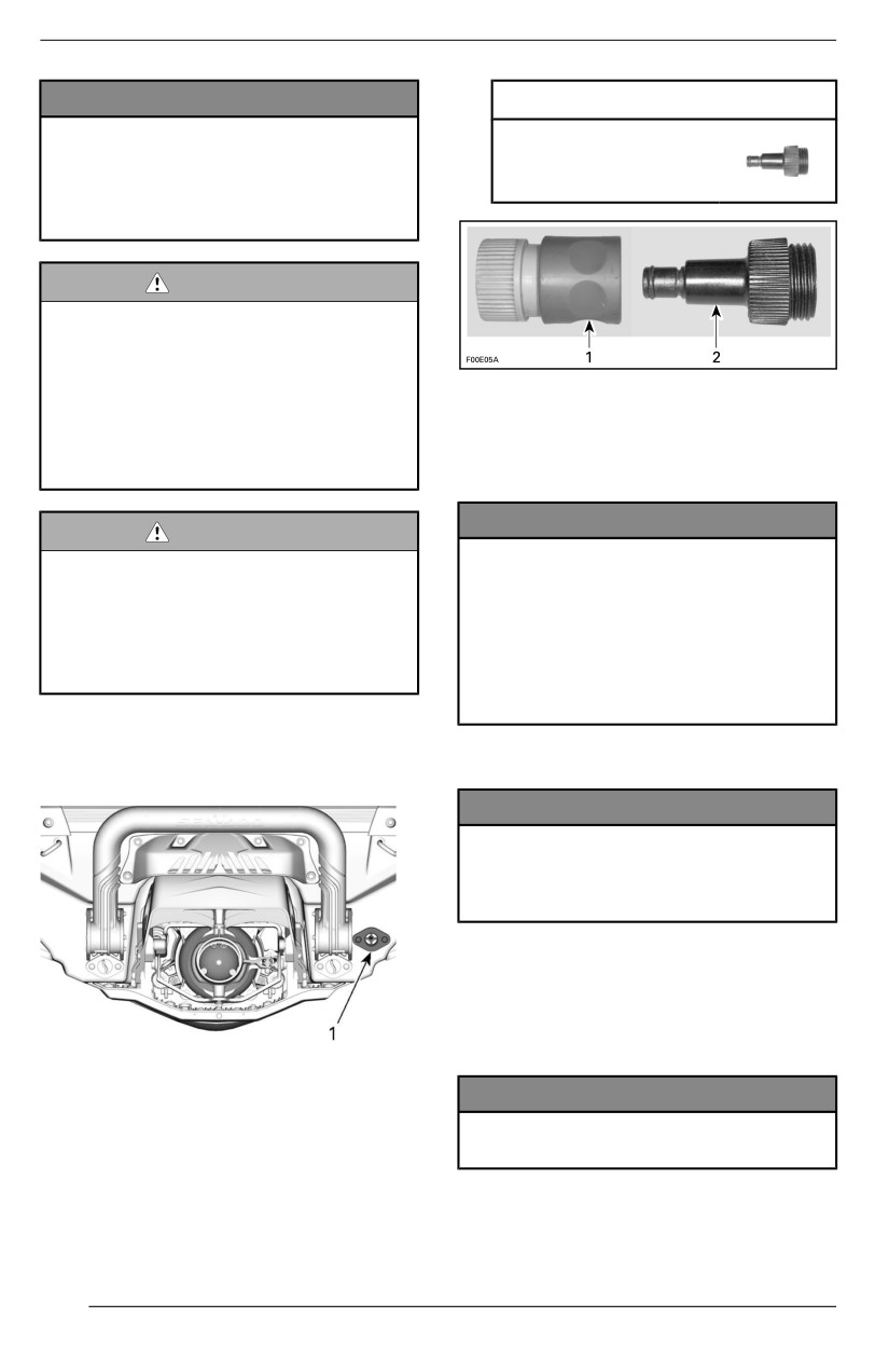
MAINTENANCE PROCEDURES
NOTICE
Recommended Tooll
Faiilure to fllush the system, when
Flushing connector
necessary, willl severelly damage
adapter
exhaust system. Make sure en-
295 500 473
giine operates during entire
procedure.
WARNING
Perform these operatiions in a welll
ventiilated area. Certain compo-
nents iin the engiine compartment
may be very hot. Direct contact
1. Quick connect adapter
may resullt in skiin burn. Do not
2. Flushing connector adapter
touch any ellectriicall part or jet
pump area when engiine iis
2. Start the engine then immediately
running.
open the water tap.
NOTICE
WARNING
Allways start the engiine before
When operating the engine whiile
openiing the water tap. Open
the watercraft is out of the water,
water tap iimmediatelly after en-
the heat exchanger iin the riide
gine is started to prevent over-
pllate may become very hot. Avoiid
heating. Never run engine without
any contact with ride plate as
supplyiing water to the exhaust
burns may occur.
system when watercraft is out of
water.
1. Connect a garden hose to connec-
tor located at the rear of watercraft.
3. Run the engine 90 seconds at idle.
Do not open water tap yet.
NOTICE
Never run engine llonger than 2
minutes. Drive liine seal has no
coolling when watercraft is out of
water.
4. Ensure water flows out of jet pump
while flushing.
5. Close the water tap, run the engine
at 5000 RPM for 5 seconds and
then stop the engine.
1. Water inlet connector
NOTICE
Allways cllose the water tap before
NOTE:
stopping the engine.
The following tool is recommended
when a quick connect adapter is used
to ease garden hose installation.
114
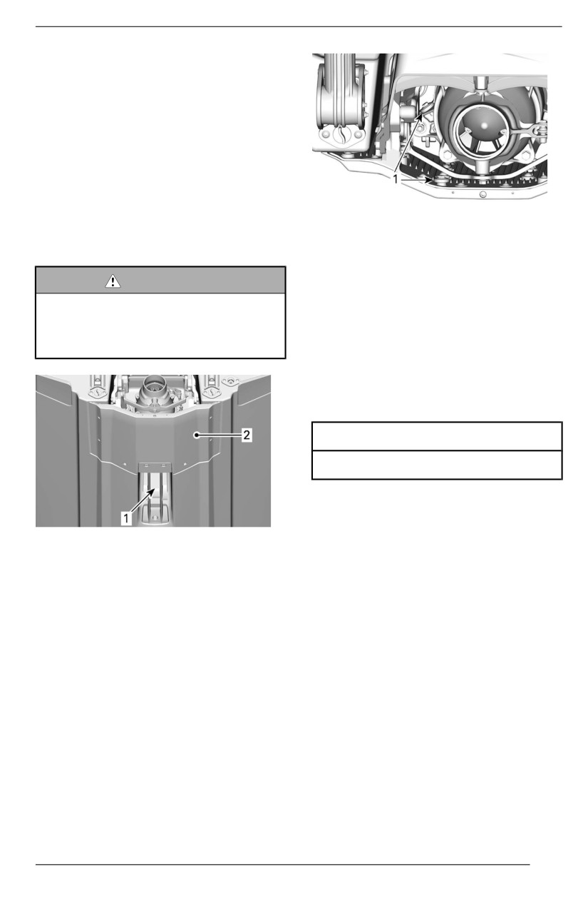
MAINTENANCE PROCEDURES
6. Disconnect the garden hose and
the flushing connector adapter (if
used).
Ride Plate and Water Intake
Grate
Inspecting the Riide Plate and the
Water Intake Grate
Inspect ride plate and jet pump water
intake grate for damage. Visit your
1. Sacrificial anodes
Sea-Doo dealer to have any damaged
part repaired or replaced.
Check sacrificial anodes for wear. If
worn more than half, replace them.
WARNING
The tether cord must allways be
Removiing the Sacrificiall Anode
removed from the engine cut-off
Unscrew sacrificial anode retaining
swiitch prior to inspecting the iin-
nut and remove anode.
take grate.
Installling the Sacriifiicial Anode
Installation is the reverse of the re-
moval procedure.
Tiightening Torque
9 ± 1 Nm (80 ± 9 lbf-in)
Fuses
INSPECT THESE AREAS
Fuse Locatiion
1. Water intake
All fuses are located inside a single
2. Ride plate
fuse box.
Sacrificial Anodes
To access the fuse box:
Remove seat(s).
Inspecting the Sacriificial Anodes
Sacrificial anodes are located on:
- Pump
– Ride plate.
115
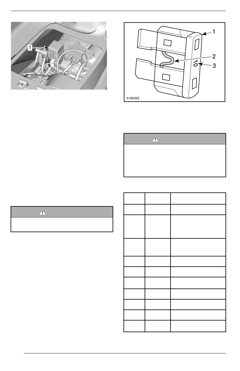
MAINTENANCE PROCEDURES
TYPICAL
1. Fuse box
TYPICAL
To remove a fuse box cover, squeeze
1. Fuse
locking tabs together, hold and pull
2. Check if melted
fuse box cover to open.
3. Ampere rating
NOTE:
WARNING
Fuse ratings and positions are illus-
trated on the fuse box cover.
If fuse burns out repeatedlly,
source of mallfunctiion should be
Use the fuse remover/installer in-
determiined and corrected before
cluded in the fuse box to ease fuse
restarting. Visit an authorized
removal.
Sea-Doo dealer for servicing.
Inspectiing a Fuse
Fuse Description
Check fuse condition and replace it if
necessary.
Fuse
Rating
Descriiptiion
1
-
Not used
WARNING
Never use a hiigher rated fuse
Fuel Inj., Ign.
than specified.
2
15 A
Coils and Fuel
Pump
To remove fuse from holder, pull fuse
Bilge Pump (if
out. Check if filament is melted.
3
3A
equipped)
4
-
Not used
5
-
Not used
6
30 A
Charge
7
5A
Cluster
8
-
Not used
9
30 A
iBR
10
5A
Start/Stop
116
MAINTENANCE PROCEDURES
Fuse
Rating
Descriiptiion
11
5A
ECM
12
30 A
Battery
13
15 A
Diagnostic Tool 2
Diagnostic Tool 1,
14
15 A
Accessory
connector
117
WATERCRAFT CARE
Remove the watercraft from the water
Many marks, as shoes marks, can be
every day.
removed easily with this method.
Post-Operation Care
Body and Hull
Fllushiing the Exhaust System
Repair
The exhaust system should be
If any repairs are needed to body
flushed daily when watercraft is used
components or to the hull, contact
in salt or foul water.
your authorized Sea-Doo dealer.
Refer to Maintenance Procedures.
Clleaniing
Wash the body and the hull with a
Addiitiionall Care for Foul Water or
soap and water solution (use only mild
Sallt Water Operation
detergent). Rinse thoroughly with
When the watercraft is operated in
fresh water.
foul water and particularly in salt
water, additional care should be taken
Remove marine organisms from the
to protect the watercraft and its
inside and outside of the hull.
components.
NOTICE
Rinse watercraft bilge area with fresh
Never clean using the followiing
water.
products:
Never use a high pressure washer to
– XPS S4 Heavy Duty Cleaner
clean the bilge. USE LOW PRES-
– Strong detergent
SURE ONLY (such as a garden
– Degreasing agent
hose).
– Ammonia
– Acetone or other ketones
High pressure can cause damages to
– Alcoholl
electrical or mechanical systems.
– Tolluene or other aromatiic
solvents
CAUTION
– Chlorinated solvents
Alllow engine to cool before per-
– Miinerall spiirits
formiing any maintenance.
– Paiint thinners
– Petroleum based products.
NOTICE
Stains may be removed from the seat
Faiilure to perform proper care
and fiberglass using the XPS All Pur-
such as: watercraft rinsing, ex-
pose Cleaner and Degreaser or the
haust system flushing and anti-
equivalent.
corrosiion treatment, when
watercraft iis used in salt water,
To clean the carpets, use 3M™ Citrus
wiilll result iin damage to the water-
Base Cleaner (24 oz spray can) or an
craft and its components. Never
equivalent.
l
leave the watercraft stored iin dii-
rect sunlight.
WARNING
Never applly pllastic or vinyl pro-
Seat Cleaning
tector on the carpets or seat as
the surface wiilll become sliippery
Before applying a cleaning product on
and the occupants may sliip off the
the seat, try removing marks with a
watercraft.
white eraser.
118
WATERCRAFT CARE
Respect the environment by ensuring
fuel, oil or cleaning solutions do not
drain into the waterways.
Protection
Apply a good quality marine wax to
the body.
If the watercraft is to be stored out-
side, cover it with an opaque tarpaulin
to prevent sun rays and grime from af-
fecting the plastic components, water-
craft finish, as well as preventing dust
accumulation.
NOTICE
The watercraft should never be
l
left in water for storage. Never
l
leave the watercraft stored in dii-
rect sunliight. Never store water-
craft iin a pllastic bag.
119
STORAGE AND PRESEASON PREPARATION
Storage
Inspecting the Jet Pump
Visit your authorized Sea-Doo dealer.
WARNING
Fuell System
Because fuel and oill are flamma-
blle, you should have an author-
Protecting the Fuel System
i
ized Sea-Doo dealer, repaiir shop,
or person of your own choosiing to
A fuel stabilizer should be added in
i
inspect the fuell system integriity
the fuel tank to prevent fuel deteriora-
as specifiied iin the periodic iin-
tion and fuel system gumming. Follow
spectiion chart.
stabilizer manufacturers' instructions
for proper use.
It is recommended that the watercraft
Service Product
be serviced by an authorized Sea-Doo
dealer, repair shop, or person of your
Fuel stabilizer
own choosing for storage, however
the following operations can be per-
formed by you with a minimum of
NOTICE
tools.
Fuel stabiiliizer shoulld be added
prior to engiine llubriication to pre-
NOTE:
vent the lloss of the chemiicall prop-
Carry out the following tasks in the
ertiies of fuell and protect the fuel
same order as detailed in this section.
system against varniish deposits.
NOTICE
Fill up fuel tank completely. Make sure
Do not run the engine during the
there is no water inside fuel tank.
storage period.
NOTICE
Propulsiion System
Should any water be trapped in-
side fuel tank, severe iinternal
Cleaning the Jet Pump
damage may occur to the fuell in-
jection system.
WARNING
Always remove tether cord from
Engine and Exhaust
the engiine cut-off swiitch to pre-
vent unexpected engine starting
Flushing the Exhaust System
before clleaniing the jet pump area.
Perform procedure as described in
Engiine must not be runniing for
Maintenance Procedures section.
this operatiion.
Replacing the Engiine Oiil and Oill
Fillter
Rinse the jet pump by spraying water
through its inlet and outlet openings.
The oil change and filter replacement
may be performed by an authorized
Spray an anti-corrosive product on the
Sea-Doo dealer, repair shop, or per-
propulsion system parts.
son of your own choosing.
Service Product
Draiiniing the Exhaust System
In areas where temperature may
XPS Anti-Corrosive Lubricant or
freeze, water trapped in the exhaust
equivalent
system and intercooler must be
removed.
120
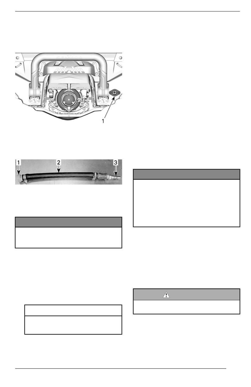
STORAGE AND PRESEASON PREPARATION
Using the flushing connector, inject
prevent fuel from being injected
pressurized air at 379 kPa (55 lbf/in²)
and disable the ignition during en-
into system until there is no more
gine cranking.
water flowing from jet pump.
4. Press the START/STOP button to
crank the engine a few turns. This
will distribute the oil on the cylinder
walls.
5. Apply anti-seize lubricant on spark
plug threads, then reinstall them in
the engine. Refer to Maintenance
Procedures section.
6. Install the ignition coils. Refer to
Maintenance Procedures section.
Testing the Engine Coollant Densiity
If antifreeze is not replaced, test its
density.
1. Flushing connector
The antifreeze replacement and a
The following hose can be fabricated
density test should be performed by
to ease draining procedure.
an authorized Sea-Doo dealer, repair
shop or person of your own choosing.
Refer to Maintenance Schedule.
NOTICE
Improper antifreeze densiity may
TYPICAL
result in freeziing of the lliquiid iin
1. Flushing connector adapter
the coolling system iif the water-
2. Hose 12.7 mm (1/2 in)
craft iis stored in an area where
3. Air hose male adapter
the freezing point is attained. This
would seriouslly damage the
NOTICE
engine.
Faiilure to drain the exhaust sys-
tem may cause severe damage to
Ellectriicall System
the exhaust manifold.
Battery
Remove special tools.
Battery Maiintenance
Lubriicating the Engiine Cyliinders
When storing the watercraft, the bat-
tery should always be stored in a
1. Remove spark plugs. Refer to
warm, dry place.
Maintenance Procedures section.
2. Spray lubricant in each cylinder
WARNING
through spark plug holes.
Never charge or boost the battery
Serviice Product
whille installled in the watercraft.
XPS Anti-Corrosive Lubricant or
This vehicle is equipped with a main-
equivalent
tenance-free type battery, there is no
3. Fully depress the throttle lever. De-
pressing the throttle lever will
121
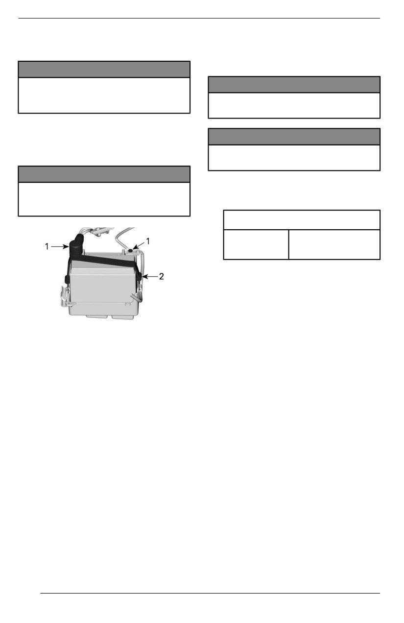
STORAGE AND PRESEASON PREPARATION
need to add water to adjust electrolyte
NOTE: Remove any water or debris
level.
if present in the compartment before
installing the battery.
NOTICE
Never remove the battery striip
NOTICE
from caps or add ellectrolyte for
Reversed battery pollarity wiilll
the liife of the battery.
damage the voltage regulator.
Removiing the Battery
NOTICE
1. Remove the seat.
2. Disconnect the battery cables.
Allways connect the RED (+) cablle
first, then the BLACK (-) cable.
NOTICE
Always disconnect the BLACK (-)
2. Tighten the battery cable screws to
cable first, then the RED (+)
specification.
cable.
Tighteniing Torque
Battery
4 ± 0.5 Nm
cable screw
(35 ± 4 lbf-in)
3. Apply dielectric grease on battery
posts.
4. Cover positive battery post with
rubber boot.
5. Verify
cable
routing
and
attachments.
1. Battery post
Engine Compartment
2. Strap
3. Remove the retaining strap.
Clleaniing the Engine Compartment
1. Clean the bilge with hot water and
Chargiing the Battery
detergent or with bilge cleaner.
Use any automotive type battery
2. Rinse thoroughly.
charger. Always refer to the battery
3. Lift front end of watercraft to com-
charger manufacturer’s instructions.
pletely drain bilge through the bilge
drain plugs.
Cleaning the Battery
Clean battery casing and battery
Antiicorrosion Treatment
posts using a soft brush and a solution
1. Wipe off any residual water in the
of baking soda and water.
engine compartment.
2. Lubricate all metallic components
Remove corrosion from battery cable
in engine compartment.
terminals and battery posts using a
firm wire brush.
Rinse with clear water then dry well.
Installling the Battery
1. Connect the battery cables.
122
STORAGE AND PRESEASON PREPARATION
Serviice Product
Lubricant and anti-corrosive or
equivalent
NOTE:
The seat should be removed during
storage. This will prevent engine com-
partment condensation and possible
corrosion.
Body and Hulll
Repair, clean and protect the water-
craft as per procedures in Watercraft
Care section.
Preseason Preparation
The preseason preparation must be
performed in conjunction with the
Maintenance Schedule.
Ensure to perform all tasks included in
the Every Year or 100 Hours table.
Preseason preparation maintenance
may be performed by an authorized
Sea-Doo dealer, repair shop or per-
son of your own choosing.
123
MAINTENANCE RECORDS
Send photocopy of maintenance record to BRP if needed.
Pre-delivery
Serial number:
Signature/Print:
Mileage / km:
Hours:
Date:
Dealer no:
Notes:
Refer to vehicle Pre-Delivery Bulletin for detailed installation procedures
124
MAINTENANCE RECORDS
First inspection
Mileage / km:
Signature/Print:
Hours:
Date:
Dealer no:
Notes:
For maintenance schedule refer to Maintenance Information section of this operator's guide
Service
Mileage / km:
Signature/Print:
Hours:
Date:
Dealer no:
Notes:
For maintenance schedule refer to Maintenance Information section of this operator's guide
125
MAINTENANCE RECORDS
Service
Mileage / km:
Signature/Print:
Hours:
Date:
Dealer no:
Notes:
For maintenance schedule refer to Maintenance Information section of this operator's guide
Service
Mileage / km:
Signature/Print:
Hours:
Date:
Dealer no:
Notes:
For maintenance schedule refer to Maintenance Information section of this operator's guide
126
MAINTENANCE RECORDS
Service
Mileage / km:
Signature/Print:
Hours:
Date:
Dealer no:
Notes:
For maintenance schedule refer to Maintenance Information section of this operator's guide
Service
Mileage / km:
Signature/Print:
Hours:
Date:
Dealer no:
Notes:
For maintenance schedule refer to Maintenance Information section of this operator's guide
127
MAINTENANCE RECORDS
Service
Mileage / km:
Signature/Print:
Hours:
Date:
Dealer no:
Notes:
For maintenance schedule refer to Maintenance Information section of this operator's guide
Service
Mileage / km:
Signature/Print:
Hours:
Date:
Dealer no:
Notes:
For maintenance schedule refer to Maintenance Information section of this operator's guide
128
MAINTENANCE RECORDS
Service
Mileage / km:
Signature/Print:
Hours:
Date:
Dealer no:
Notes:
For maintenance schedule refer to Maintenance Information section of this operator's guide
Service
Mileage / km:
Signature/Print:
Hours:
Date:
Dealer no:
Notes:
For maintenance schedule refer to Maintenance Information section of this operator's guide
129
MAINTENANCE RECORDS
Service
Mileage / km:
Signature/Print:
Hours:
Date:
Dealer no:
Notes:
For maintenance schedule refer to Maintenance Information section of this operator's guide
Service
Mileage / km:
Signature/Print:
Hours:
Date:
Dealer no:
Notes:
For maintenance schedule refer to Maintenance Information section of this operator's guide
130
MAINTENANCE RECORDS
Service
Mileage / km:
Signature/Print:
Hours:
Date:
Dealer no:
Notes:
For maintenance schedule refer to Maintenance Information section of this operator's guide
Service
Mileage / km:
Signature/Print:
Hours:
Date:
Dealer no:
Notes:
For maintenance schedule refer to Maintenance Information section of this operator's guide
131
MAINTENANCE RECORDS
This page is intentionally blank
132
TECHNICAL INFORMATION
133
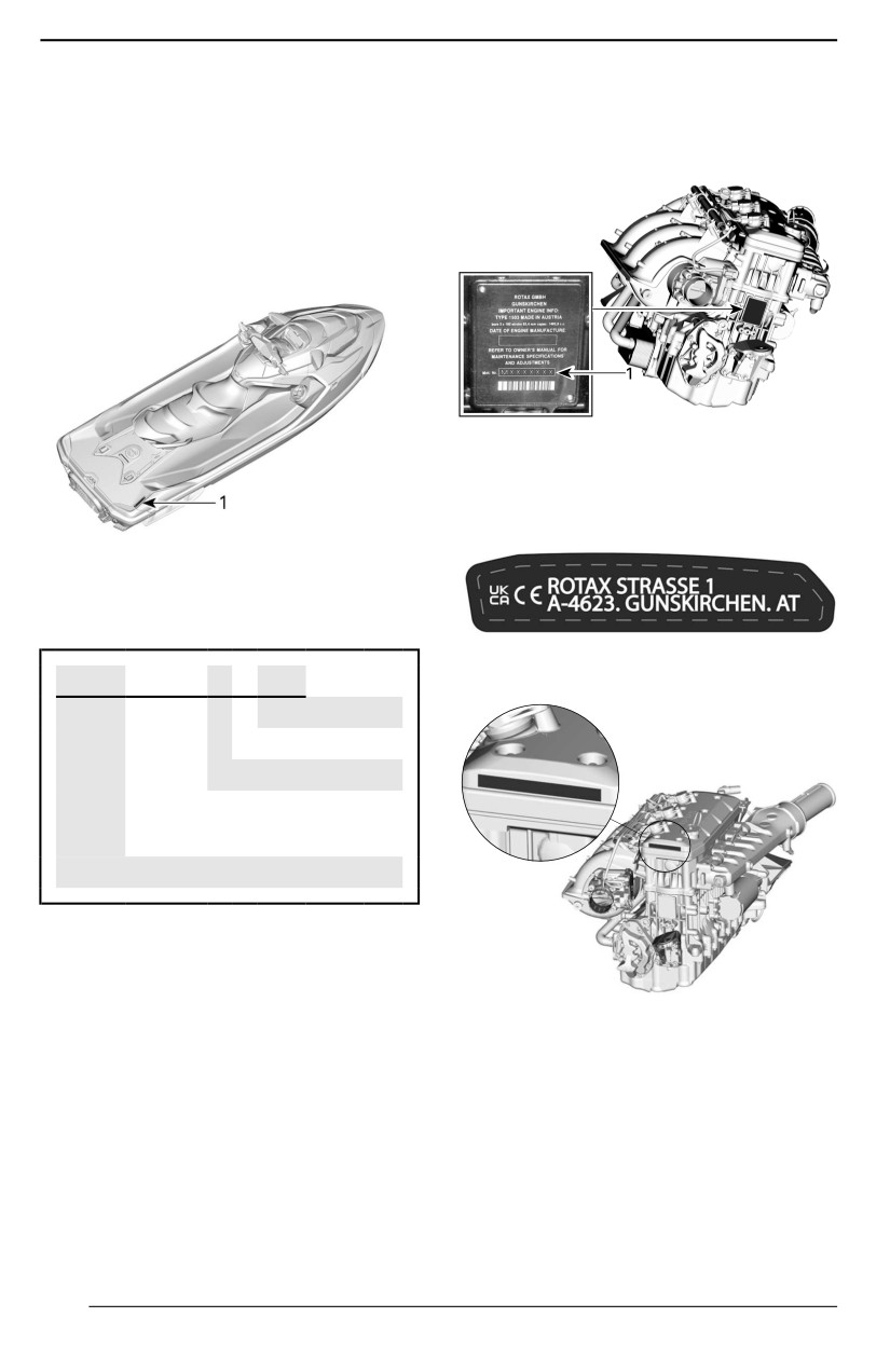
IDENTIFICATION NUMBERS
The main components of the watercraft (engine and hull) are identified by differ-
ent serial numbers. It may sometimes become necessary to locate these num-
bers for warranty purposes or to trace the watercraft in the event of theft.
Hull Identification Number
The Hull Identification Number (HIN)
is located on footboard at the rear of
watercraft.
TYPICAL
1. Engine Identification Number (EIN)
Engine Manufacturer
Identification
TYPICAL
1. Hull Identification Number (HIN)
It is composed of 12 digits:
ENGINE MANUFACTURER IDENTIFICA-
TION LABEL
YDV
12345
L 8
09
Model year
Year of production
Month of production
Serial number
(a letter may also be used as a
digit)
Manufacturer
Engine Identification Number
The Engine Identification Number
(EIN) is located on the front end of the
LABEL LOCATION
engine.
134

COMPLIANCE
Emission Control Hang Tag – 3 Stars
Bombardier Recreational Products Inc.
VALCOURT,QUÉBEC, CANADA.
EMISSION CONTROL HANG TAG - 3 STARS
135
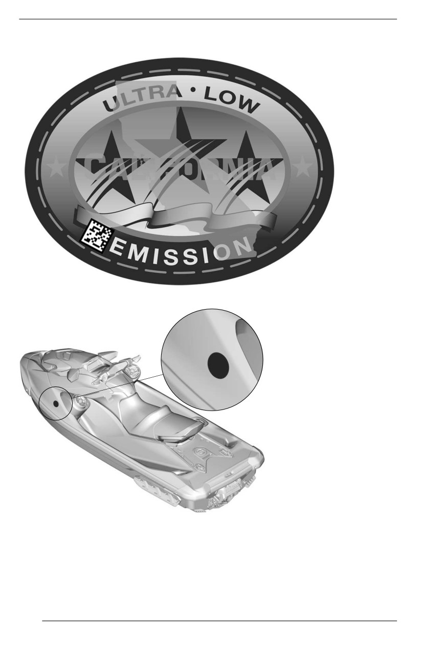
COMPLIANCE
Emission Control Label – 3 Stars
EMISSION CONTROL LABEL - 3 STARS
TYPICAL – LABEL LOCATION
136
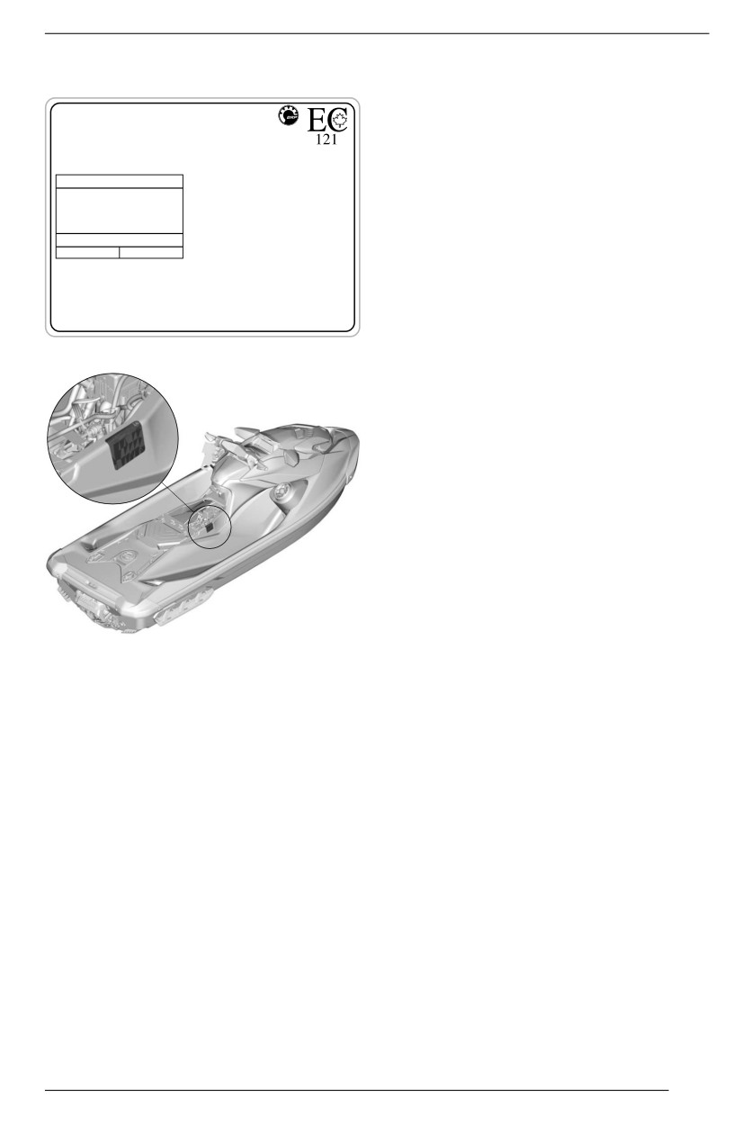
COMPLIANCE
EPA Compliance Label
EMISSION CONTROL SYSTEM INFORMATION
BOMBARDIER RECREATIONAL PRODUCTS INC.
THIS ENGINE CONFORMS TO
U.S. EPA & CALIFORNIA
EMISSIONS REGULATIONS FOR MARINE SI ENGINES.
RENSEIGNEMENT SUR LE DISPOSITIF ANTIPOLLUTION
CE MOTEUR EST CONFORME AUX NORMES
DE L’EPA
DES É.-U. POUR LES MOTEURS MARINS À ALLUMAGE COMMANDÉ.
ENGINE FAMILY / FAMILLE DE MOTEUR
( EPA
FEL)
CERTIFICATION STANDARDS
CA
NORMES DE CERTIFICATION
(
FEL
)
EMISSION CONTROL SYSTEM
SYSTÈME DE CONTRÔLE DES ÉMISSIONS
MEETS
CALIFORNIA EVAP EMISSIONS REGULATIONS FOR SPARK
IGNITION MARINE WATERCRAFT. EVAP FAMILY
EVAPORATIVE EMISSION CONTROL SYSTEM: SO
SEE OPERATOR’S GUIDE FOR MAINTENANCE SCHEDULE AND FUEL,
OIL AND SPARK PLUG SPECIFICATIONS. VOIR LE CALENDRIER
D’ENTRETIEN ET LES SPÉCIFICATIONS D’ESSENCE, D’HUILE ET DE
BOUGIE D’ALLUMAGE DANS LE GUIDE DE L’OPÉRATEUR.
219905703
EPA COMPLIANCE LABEL
TYPICAL – LABEL LOCATION
137
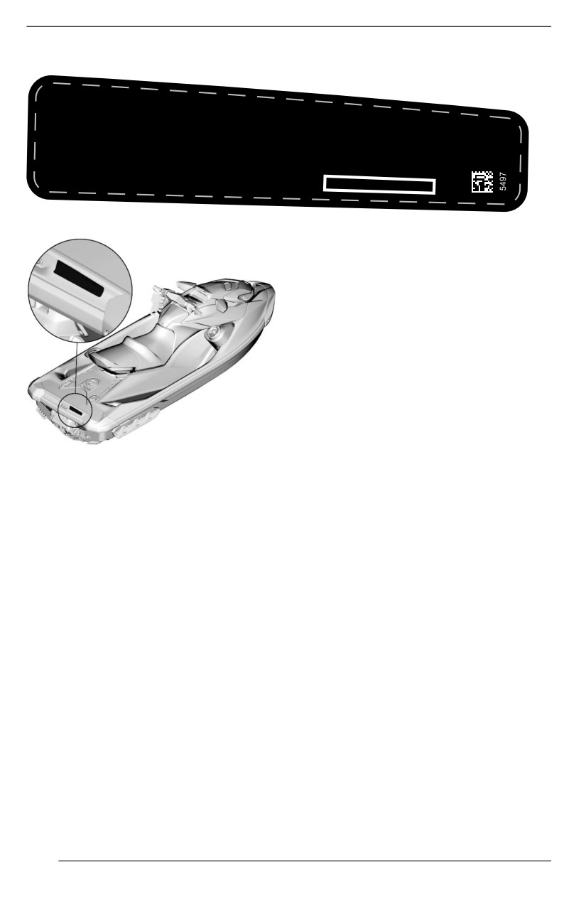
COMPLIANCE
Regulation Exemption Label
THIS BOAT IS MANUFACTURED BY
BOMBARD
GRANT OFIER RECREATIONAL PRODUCTS INC. PER 46 U.S.C. 4305 AND U.S. COAST GUARD
IS VESSE
L FROM ONE OR MORE
SAFETY REGULATIONS. CGB 88-001 STATES THAT CERTAIN REGULA
TIONS ARE INAPPLICABLE IN LIGHT
ILL NOT HAVE AN ADVERSE EFFECT
ON RECREATIONAL BOATING SAFETY. THIS BOAT COMPLIES WITH
U.S. COAST GUARD SAFETY
SONS SHOULD WEAR A
LIFEJACKET (PERSONAL FLOTATION DEVICE) WHILE
OPERATING OR RIDING ON THIS WATERCRAFT.
ASSEMBLED IN MEXICO
REGULATION EXEMPTION LABEL
TYPICAL – LABEL LOCATION
138
COMPLIANCE
BRP European Distribution SA
BRP is a member of the Association for Eco-Responsible Pleasure Craft, dedi-
cated to the dismantling and recycling of pleasure boats and personal watercraft
at the end of their life. The Unique Producer Identifier of BRP European Distribu-
tion SA is: FR219503_18XCIB
REP France - TRIMAN
Signage
For France only
139
RF D.E.S.S. KEY
This device complies with FCC Part 15 and Industry Canada license exempt
RSS standard(s).
Operation is subject to the following two conditions: (1) this device may not cause
interference, and (2) this device must accept any interference, including interfer-
ence that may cause undesired operation of the device.
Changes or modifications not expressly approved by the party responsible for
compliance could void the user’s authority to operate the equipment.
IC Registration Number: 12006A-1001317030
FCC ID: 2ACER-1001317030
We, the party responsible for compliance, declare under our sole responsibility
that the device is in conformity with the provisions of the following Council Direc-
tive: 2014/53/EU. To which this declaration relates is in conformity with the es-
sential requirements and other relevant requirements. The product is in
conformity with the following directives, harmonized standards and regulations:
Radio Equipment Directive (RED) 2014/53/EU and Harmonized Standards:
EN 300 330-2, EN 60950-1
This device complies with part 15 of the FCC Rules. Operation is subject to the
following two conditions: (1) This device may not cause harmful interference, and
(2) this device must accept any interference received, including interference that
may cause undesired operation.
Changes or modifications not expressly approved by the party responsible for
compliance could void the user's authority to operate the equipment.
This device contains licence-exempt transmitter (s)/receiver (s) that comply with
Innovation, Science and Economic Development Canada’s licence-exempt RSS
(s). Operation is subject to the following two conditions:
(1) This device may not cause interference.
(2) This device must accept any interference, including interference that may
cause undesired operation of the device.
L’émetteur/récepteur exempt de licence contenu dans le présent appareil est
conforme aux CNR d’Innovation, Sciences et Développement économique Can-
ada applicables aux appareils radio exempts de licence. L’exploitation est autori-
sée aux deux conditions suivantes:
(1) l'appareil ne doit pas produire de brouillage;
(2) l'appareil doit accepter tout brouillage radioélectrique subi, même si le brouil-
lage est susceptible d'en compromettre le fonctionnement.
140
RF D.E.S.S. KEY
Radio Equipment Directive (RED)
2014/53/EU
Safety and health
Article 3.1a
IEC 62368-1:2014
EMC
CISPR 25:(2016); conducted
emission
Article 3.1b
CISPR 25:(2016); radiated emission
ISO 11452-2 (2004); radiated
electromagnetic field immunity
Spectrum usage efficiency
Article 3.2
ETSI EN 300 330 V2.1.1 (2017-2)
141
ENGINE EMISSIONS INFORMATION
Manufacturer''s
EPA Emission Regulations
Responsibility
Sea-Doo SIPME manufactured by
Manufacturers of marine engines
BRP are certified to the EPA as con-
must determine the exhaust emission
forming to the requirements of the reg-
levels for each engine horsepower
ulations for the control of air pollution
family and certify these engines with
from new SIPME. This certification is
the United States of America Environ-
contingent on certain adjustments
mental Protection Agency (EPA). An
being set to factory standards. For this
emissions control information label,
reason, the factory procedure for serv-
showing emission levels and engine
icing the product must be strictly fol-
specifications, must be placed on
lowed and, whenever practicable,
each Spark-Ignition Propulsion Marine
returned to the original intent of the
Engines
(SIPME) at the time of
design.
manufacture.
The responsibilities listed above are
general and in no way a complete list-
Dealer''s Responsibility
ing of the rules and regulations per-
When performing service on a Sea--
taining to the EPA requirements on
Doo SIPME that carry an emissions
exhaust emissions for marine prod-
control information label, adjustments
ucts. For more detailed information on
must be kept within published factory
this subject, you may contact:
specifications.
U. S. Environmental Protection
Replacement or repair of any emis-
Agency
sion related component must be exe-
Certification Division
cuted in a manner that maintains
Gasoline Engine Compliance Center
emission levels within the prescribed
2000 Traverwood Drive
certification standards.
Ann Arbor MI 48105
USA
Dealers are not to modify the engine
in any manner that would alter the
horsepower or allow emission levels
EPA INTERNET WEB SITE:
to exceed their predetermined factory
specifications.
Evaporative Emission
Exceptions include manufacturer's
Control System
prescribed changes, such as altitude
adjustments for example.
Spark-Ignition Marine Watercraft
(SIMW) sold in the State of California
Owner’s Responsibility
are certified to the California evapora-
tive emissions regulations for SIMW of
The owner/operator is required to
the California Air Resources Board
have engine maintenance performed
(13 CCR 2850 to 2869). These mod-
to maintain emission levels within pre-
els are equipped with an evaporative
scribed certification standards.
emission control system consisting of
Low Permeation Fuel Tank (LPFT),
The owner/operator is not to, and
Low Permeation Fuel Line (LPFL) and
should not allow anyone to modify the
a Pressure Relief Valve (PRV).
engine in any manner that would alter
the horsepower or allow emissions
levels to exceed their predetermined
factory specifications.
142
EU DECLARATION OF CONFORMITY
Left blank for EU Conformity
143
UK DECLARATION OF CONFORMITY
Left blank for UK Conformity
144
EAC DECLARATION OF CONFORMITY
Left blank for Eurasian Conformity
mark where applicable
145
EAC DECLARATION OF CONFORMITY
This page is intentionally blank
146
TECHNICAL
SPECIFICATIONS
147
ENGINE
Rotax 1630 ACE -
130
ENGINE
Rotax 1630 ACE - 130
4-stroke, Single Over Head
Engine type
Camshaft (SOHC)
Declared Power(1)
100 kW @ 6000 RPM
Induction
Naturally-Aspirated
Number of cylinders
3
12 valves with hydraulic lifters
Number of valves
(no adjustment)
Bore
100 mm (3.9 in)
Stroke
69.2 mm (2.7 in)
Displacement
1 630.5 cm³ (99.5 in³)
Compression ratio
11:1
FUEL SYSTEM
Multipoint fuel injection with iTC
(intelligent Throttle Control).
Fuel injection type
Single throttle body (60 mm)
with an actuator
Idle speed (not adjustable)
1800 ± 50 RPM
ELECTRICAL SYSTEM
IDI (Inductive Discharge
Ignition system type
Ignition)
NGK, DCPR8E with solid post
Type
or equivalent
Spark plug(2)
0.80 to 0.90 mm
Gap
(.031 to .035 in)
LUBRICATION
General
5W40 Synthetic blend oil
purpose
Recom
Engine oil(3)
mended
Warm
XPS oil
tempera
10W50 Synthetic oil
ture
148

ENGINE
LUBRICATION
Use a 4-stroke SAE
motorcyclle engiine oiil
compatible with wet
clutches meeting or
exceeding the following
lubricant industry
specifications.
Alternate oil if XPS
Always check the API
products are not
service label certification
available
on the oil container, it
must contain at least one
of the indicated
standards.
API serviice
classiifiicatiion SN or
JASO-MA2
Oil change
3l
with filter
(3.2 qt (liq.,US))
Capacity
5l
Total
(5.3 qt (liq.,US))
(1)
Declared power as per ISO 8665 at propeller-shaft.
(2)
NOTICE
Do not attempt to adjust gap on this spark plug.
(3)
Refer to Engine Oil for detailed information.
149

VEHICLE
GTX PRO 130
Cooliing System
Closed-loop cooling system
Type
(CLCS)
XPS Extended life pre-mixed
Recommended
coolant
Use a low silicate, extended
life ethylene-glycol premixed
Alternative, or if
coolant (50%-50%)
Coolant
not available
specifically formulated for
internal combustion
aluminum engines.
5.4 l
Capacity
(5.7 qt(liq.,US))
Fuell System
Fuel pump
In-tank electrical
Regular unleaded
Type
Refer to Fuel Requirements
Fuel
87 Pump Posted AKI
(RON+MON)/2
Octane rating
or
91
(RON) E10
Full
70 l (18.5 gal(liq. US))
Tank capacity
Reserve
(from low level
14 l (3.7 gal(liq. US))
signal - approx.)
Electriicall System
Batter
12 V, 18 Ah
Total system output
420 W @ 6000 RPM
Fuel Inj., Ign.
F2
Coils and Fuel
15 A
Pump
Fuses
Bilge pump (if
F3
3A
equipped)
F6
Charge
30 A
150
VEHICLE
F7
Cluster
5A
F9
iBR
30 A
F10
Start/ Stop
5A
F11
ECM
5A
F12
Battery
30 A
Diagnostic
Connector (6),
F13
15 A
Accessory
connector (2)
Diagnostic
Connector (5),
F14
15 A
Accessory
connector (1)
Relay
RY1
Main
—
Propulsion
Propulsion system
Sea-Doo® jet pump
Axial flow, single stage.
Type
Large hub with double row
Jet pump
ball bearings
Material
Aluminum
Impeller
Stainless steel
Transmission
Type
Direct drive
Weiight and Loading Capacity
Dry weight
356 kg (785 lb)
Number of passenger (driver incl.)
3
Load limit (passenger(s) and luggage,
272 kg
including accessories)
(600 lb)
Storage capacity
98.9 l (26.1 gal(liq.,US))
151
VEHICLE
Dimensions
Overall length
345.1 cm (135.9 in)
Overall width
125.5 cm (49.4 in)
Overall height
114 cm (44.9 in)
NOTE:
BRP reserves the right to make changes in design and specifications and/or to
make additions to, or improvements in its products without imposing any obliga-
tion upon itself to install them on its products previously manufactured.
152
TROUBLESHOOTING
153
TROUBLESHOOTING GUIDELINES
ENGINE WILL NOT START
1. Master swiitch opened.
- Close the master switch.
2. Tether cord removed.
- Press START/STOP button.
- Install tether cord cap over engine cut-off switch within 5 seconds after
depressing the START/STOP button.
- Press START/STOP button.
3. ECM does not recogniize the D.E.S.S. key.
- Refer to an authorized Sea-Doo dealer.
4. Burnt fuse: maiin, ellectric starter or ECM.
- Check wiring then replace fuse(s).
5. Diischarged battery.
- Refer to an authorized Sea-Doo dealer.
WARNING
Do not charge or boost the battery whille iinstallled on the watercraft.
Electrollyte iis poisonous and dangerous. Avoiid contact with eyes, skin
and clothing.
6. Battery connectiions, corroded or lloose. Bad ground.
- Refer to an authorized Sea-Doo dealer.
7. Water-fllooded engiine.
- Refer to Water-Flooded Engine in Special Procedures.
8. Faulty sensor or ECM.
- Seek service from an authorized Sea-Doo dealer, repair shop, or
person of your own choosing for maintenance, repair, or replacement.
Please refer to the US EPA Emission-Related Warranty contained
herein for information about warranty claims.
9. Seized jet pump.
- Try to clean. Otherwise, refer to an authorized Sea-Doo dealer.
ENGINE CRANKS SLOWLY
1. Loose battery cable connectiions.
- Check/clean/tighten.
2. Diischarged or weak battery.
- Refer to an authorized Sea-Doo dealer.
3. Worn starter.
- Refer to an authorized Sea-Doo dealer.
154
TROUBLESHOOTING GUIDELINES
ENGINE TURNS NORMALLY BUT WILL NOT START
1. Fuell tank empty or water-contaminated.
- Refill. Siphon and fill with fresh fuel.
2. Foulled/defectiive spark pllugs.
- Replace.
3. Blown fuse.
- Check wiring then replace fuse(s).
4. Water-fllooded engine.
- Refer to Water-Flooded Engine in Special Procedures.
5. Engiine management system faullt detected (check engine pillot llamp
i
is ON).
– Seek service from an authorized Sea-Doo dealer, repair shop, or
person of your own choosing for maintenance, repair, or replacement.
Please refer to the US EPA Emission-Related Warranty contained
herein for information about warranty claims.
6. Faullty fuell pump.
- Seek service from an authorized Sea-Doo dealer, repair shop, or
person of your own choosing for maintenance, repair, or replacement.
Please refer to the US EPA Emission-Related Warranty contained
herein for information about warranty claims.
ENGINE MISFIRES, RUNS IRREGULARLY
1. Foulled/defectiive/worn spark pllugs.
- Replace.
2. Fuell: Levell too llow, stalle or water-contamiinated.
- Siphon and/or refill.
3. Faullty iigniitiion coill(s).
- Seek service from an authorized Sea-Doo dealer, repair shop, or
person of your own choosing for maintenance, repair, or replacement.
Please refer to the US EPA Emission-Related Warranty contained
herein for information about warranty claims.
4. Clogged injectors.
- Seek service from an authorized Sea-Doo dealer, repair shop, or
person of your own choosing for maintenance, repair, or replacement.
Please refer to the US EPA Emission-Related Warranty contained
herein for information about warranty claims.
5. Engiine management system faullt detected (check engine pillot llamp
i
is ON).
– Refer to Monitoring System.
155
TROUBLESHOOTING GUIDELINES
ENGINE SMOKE
1. Oill levell too hiigh.
- Seek service from an authorized Sea-Doo dealer, repair shop, or
person of your own choosing for maintenance, repair, or replacement.
Please refer to the US EPA Emission-Related Warranty contained
herein for information about warranty claims.
2. Water ingestiion, coollant lleak or damaged cyllinder head gasket.
- Seek service from an authorized Sea-Doo dealer, repair shop, or
person of your own choosing for maintenance, repair, or replacement.
Please refer to the US EPA Emission-Related Warranty contained
herein for information about warranty claims.
3. Internall engiine damage.
- Seek service from an authorized Sea-Doo dealer, repair shop, or
person of your own choosing for maintenance, repair, or replacement.
Please refer to the US EPA Emission-Related Warranty contained
herein for information about warranty claims.
ENGINE OVERHEATS
1. Cllogged exhaust system.
- Flush exhaust system.
2. Engine coollant level too low.
- Refer to Maintenance Procedures.
3. Quiick connect adapter lleft iin fllushiing connector.
- Remove adapter from flushing connector and retry watercraft. If
problem persists, seek service from an authorized Sea-Doo dealer,
repair shop, or person of your own choosing for maintenance, repair, or
replacement. Please refer to the US EPA Emission-Related Warranty
contained herein for information about warranty claims.
156
TROUBLESHOOTING GUIDELINES
ENGINE LACKS ACCELERATION OR POWER
1.
Learning key used.
- Use a Normal key.
2.
Not in Sport mode.
- Select Sport mode.
3.
Jet pump water iintake cllogged.
- Clean. Refer to Jet Pump Water Intake and Impeller Cleaning in Special
Procedures section.
4.
Damaged iimpelller or worn-out wear riing.
- Replace. Refer to an authorized Sea-Doo dealer.
5.
Engiine oiil llevell too high.
- Seek service from an authorized Sea-Doo dealer, repair shop, or
person of your own choosing for maintenance, repair, or replacement.
Please refer to the US EPA Emission-Related Warranty contained
herein for information about warranty claims.
6.
Weak spark.
- Refer to ENGINE MISFIRES, RUNS IRREGULARLY.
7.
Engiine management system faullt detected (check engine pillot llamp
i
is ON).
– Refer to Monitoring System.
8.
Clogged injectors.
- Seek service from an authorized Sea-Doo dealer, repair shop, or
person of your own choosing for maintenance, repair, or replacement.
Please refer to the US EPA Emission-Related Warranty contained
herein for information about warranty claims.
9.
Low fuel pressure.
- Seek service from an authorized Sea-Doo dealer, repair shop, or
person of your own choosing for maintenance, repair, or replacement.
Please refer to the US EPA Emission-Related Warranty contained
herein for information about warranty claims.
10. Water iin fuell.
- Siphon and replace.
11. Engiine damaged by water ingestiion.
- Refer to an authorized Sea-Doo dealer.
157
TROUBLESHOOTING GUIDELINES
WATERCRAFT CAN NOT REACH TOP SPEED
1. Jet pump water intake clogged.
- Clean. Refer to Jet Pump Water Intake and Impeller Cleaning in Special
Procedures section.
2. Damaged impelller or worn-out wear ring.
- Replace. Refer to an authorized Sea-Doo dealer.
3. Engine management system fault detected (check engiine piilot lamp
is ON).
- Refer to Monitoring System.
WATERCRAFT STAYS IN NEUTRAL AFTER OPERATING THE iBR
LEVER
1. The iBR gate stays in neutrall.
- Release the throttle to idle RPM.
i
iBR WILL NOT RETURN TO NEUTRAL POSITION (iiBR INDICATOR
LIGHT ON)
1. iBR jjammed wiith debris.
- Clean and check for damage in the iBR gate and nozzle area.
2. iBR system malfunctiion.
- Remove tether cord, wait four minutes, reinstall key and check iBR light
to ensure fault is cleared.
- Refer to an authorized Sea-Doo dealer if fault persists or reoccurs
frequently.
i
iBR WILL NOT RETURN TO NEUTRAL POSITION (IBR INDICATOR
LIGHT OFF)
1. Throttle llever not fullly released during operation.
- Release throttle lever fully to ensure iBR gate returns to neutral.
2. Throttle llever does not fullly return to nulll when relleased.
- Refer to an authorized Sea-Doo dealer.
158
TROUBLESHOOTING GUIDELINES
ABNORMAL NOISE FROM PROPULSION SYSTEM
1. Weeds or debriis jammed around impelller.
- Clean. Refer to Jet Pump Water Intake and Impeller Cleaning in Special
Procedures section.
- Check for damage.
2. Damaged iimpelller shaft or drive shaft.
- Refer to an authorized Sea-Doo dealer.
3. Water iintrusion iin jjet pump causiing bearing seiizure.
- Refer to an authorized Sea-Doo dealer.
WATER FOUND IN BILGE
1. Billge pump system malfunction.
- Have system inspected by an authorized Sea-Doo dealer.
2. Exhaust system leak.
- Refer to an authorized Sea-Doo dealer.
3. Carbon riing at drive shaft worn.
- Refer to an authorized Sea-Doo dealer.
4. Hulll and/or Deck seal diispllaced or fasteners loose.
- Refer to an authorized Sea-Doo dealer.
159
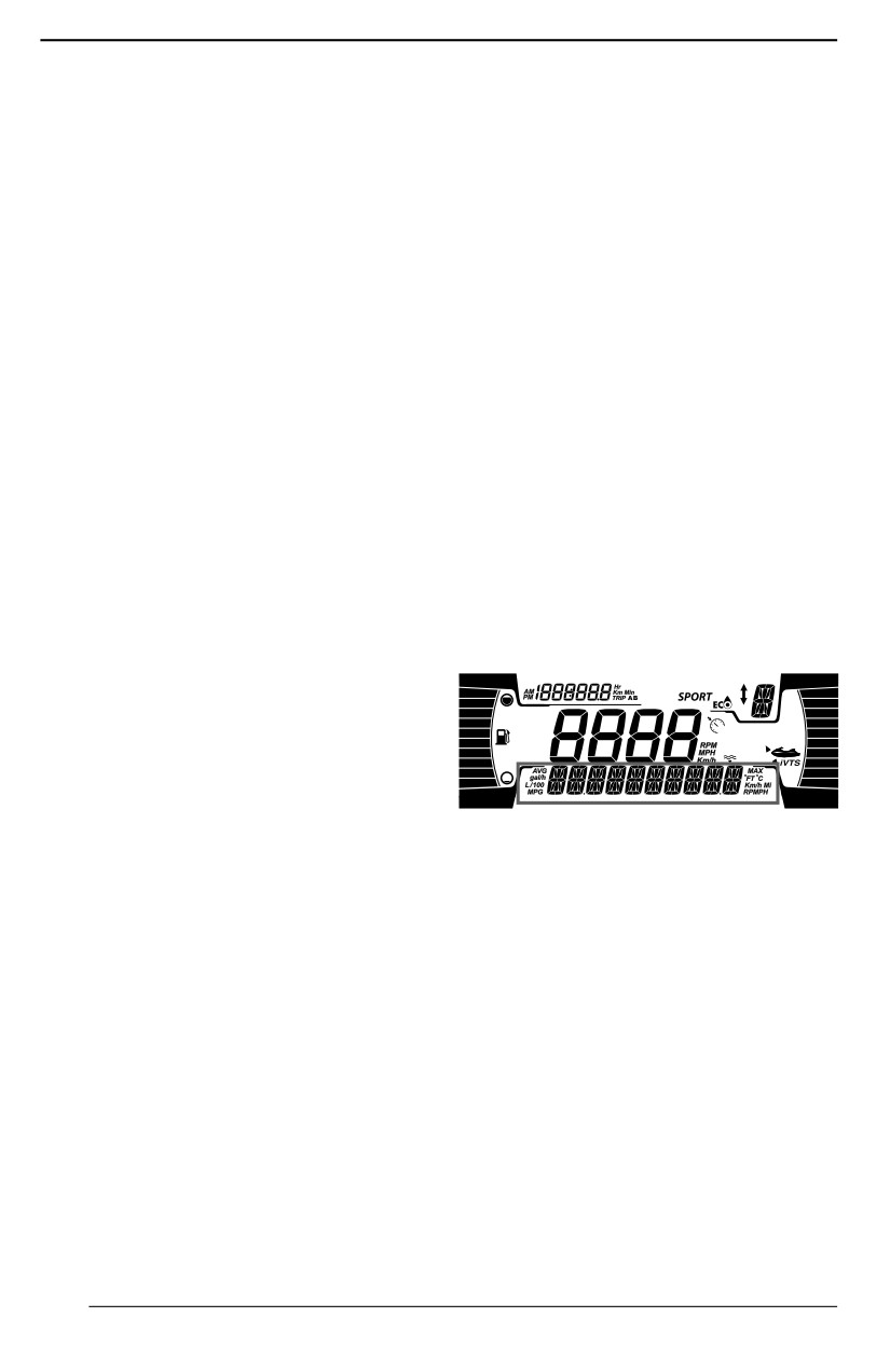
MONITORING SYSTEM
A system monitors the electronic com-
then choose to call his authorized
ponents of the EMS (engine manage-
Sea-Doo dealer to pass on the fault
ment system) iBR, and other
code. The dealer will then advise the
components of the electrical system.
operator on the steps to take to solve
When a fault occurs, it sends visual
the problem, or to stop using the
messages through the information
watercraft and to bring it in to the deal-
center and/or audible signals through
er for repairs.
a beeper to inform you of a particular
condition.
Diispllayiing Faullt Codes
Select CODES. If a fault code has oc-
A fault code may also be recorded.
curred during your riding cycle, a CO-
When a minor or transient fault oc-
DES menu will be available in the
curs, the fault message and beeper
settings menu. Press OK to see the
will cease automatically if the condi-
list of faults.
tion that caused the fault does not ex-
ist anymore.
NOTE:
During normal riding conditions some
Releasing the throttle and letting the
fault codes may occur. Before con-
engine return to idle speed may allow
tacting your local dealer, remove the
normal operation to come back. If this
key, make sure to wait 2 minutes until
does not work, try removing and rein-
the electrical system shut down, then
stalling the tether cord on the engine
press start to wake up the electrical
cut-off switch.
system. This will ensure occurred fault
to disappear and only the active codes
The electronic system will react differ-
will remain ON in the CODES menu.
ently depending on the fault type. In
severe failure, the engine may not be
allowed to be started. In other cases,
the engine will operate in limp home
mode (reduced speed).
When a fault occurs, please refer to
the US EPA Emission-Related War-
ranty contained herein for information
about warranty claims.
Fault Codes
When a fault occurs, a numerical fault
code may be recorded depending on
the fault type and system.
These fault codes are used by author-
ized Sea-Doo dealers for trouble-
shooting the watercraft systems when
comparing them to a fault list.
Fault codes can be viewed in the infor-
mation center multifunction display
however, this function is only available
if a fault is still active.
If there is an active fault code, it may
be viewed by the operator on the mul-
tifunction display. The operator may
160
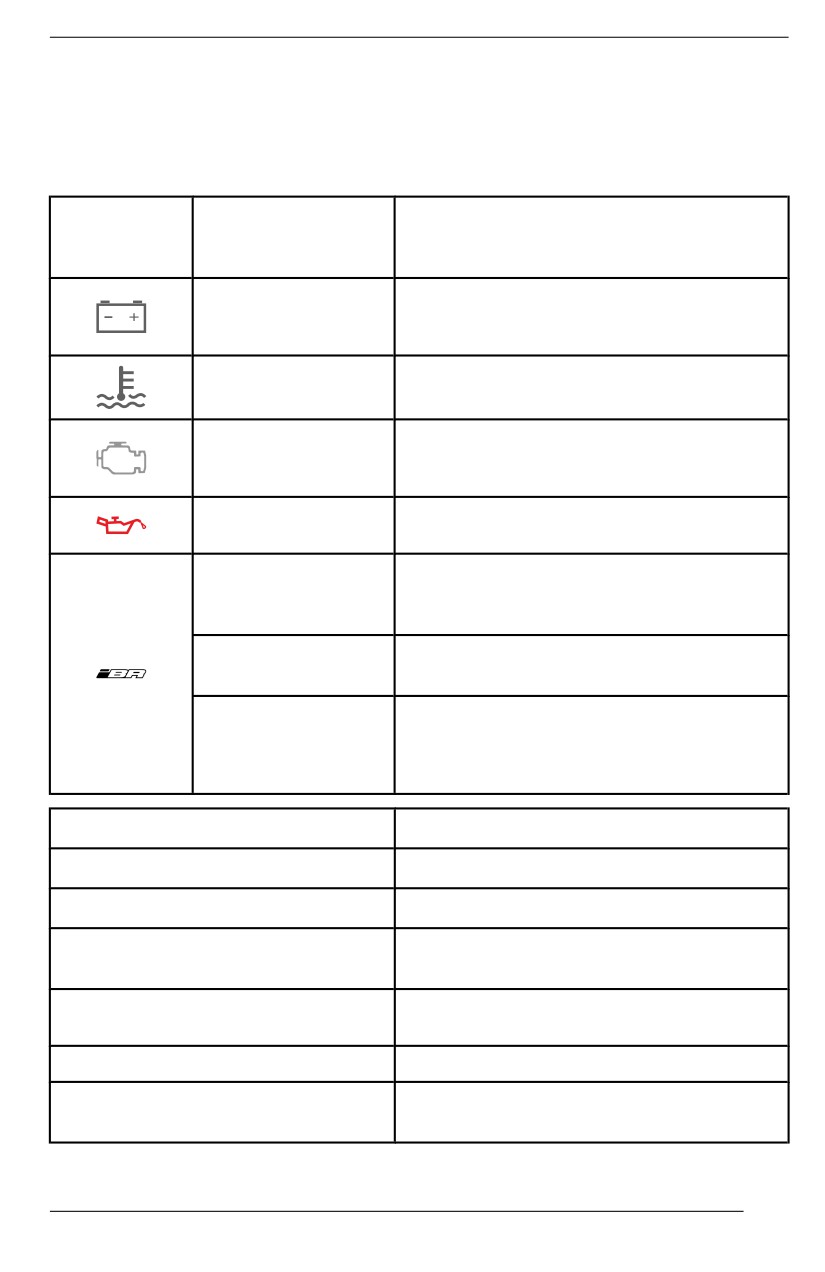
MONITORING SYSTEM
Indicator Lights and Message Display Information
The indicator lights (pilot lamps) and messages displayed in the information cen-
ter will inform you of a particular condition or if an anomaly occurs.
For information on usual indicator lights, refer to appropriate digital display.
Indiicator
Liight / Icon
Message Display
Descriiptiion
(ON)
LOW or HIGH
BATTERY
Low/high battery voltage
VOLTAGE
HIGH
Engine or exhaust system overheating
TEMPERATURE
CHECK ENGINE
Check engine (minor fault req. maint.) or
or LIMP HOME
LIMP HOME MODE (major eng. fault)
MODE
LOW OIL
Low oil pressure
PRESSURE
Light is steady with a buzzer and a
IBR MODULE
check engine light: iBR system fault
ERROR
(refer to an authorized Sea-Doo dealer)
Light is flashing: iBR system fault (refer
_
to an authorized Sea-Doo dealer)
Light is steady with no buzzer:
iBR system still functional but needs to
_
be inspected by an authorized Sea-Doo
dealer
Message Display
Descriiptiion
HIGH EXHAUST TEMPERATURE
High exhaust temperature detected
HIGH ENGINE TEMPERATURE
High engine temperature detected
Engine system malfunction and/or
CHECK ENGINE
requiring maintenance
Major fault detected, engine power
LIMP HOME MODE
limited
FUEL SENSOR FAULT
Fuel level sensor fault
WATER TEMP SENSOR
Problem with water temperature sensor,
DEFECTIVE
not sending water temperature info.
161
MONITORING SYSTEM
Message Diispllay
Description
IBR MODULE ERROR
iBR system malfunction
MAINTENANCE REQUIRED
Watercraft maintenance required
NOTICE
Running engiine with low oill pressure may severely damage the engiine.
162

MONITORING SYSTEM
Beeper Code Information
Beeper Codes
Description
Bad D.E.S.S. system connection.
Reinstall tether cord cap correctly on the engine
cut-off switch.
Wrong D.E.S.S. key.
Use a tether cord that has been programmed for the
watercraft.
Defective D.E.S.S. key.
1 long beep
Use another tether cord with programmed D.E.S.S.
(while installing tether
key.
cord on watercraft
engine cut-off switch)
Defective engiine cut-off swiitch.
Refer to an authorized Sea-Doo dealer.
Improper operatiion of ECM or defective wiriing
harness.Seek service from an authorized Sea-Doo
dealer, repair shop, or person of your own choosing
for maintenance, repair, or replacement. Please
refer to the US EPA Emission-Related Warranty
contained herein for information about warranty
claims.
Engine management system faullt.
Seek service from an authorized Sea-Doo dealer,
repair shop, or person of your own choosing for
A 2 seconds beep
maintenance, repair, or replacement. Please refer to
every 15 minutes
the US EPA Emission-Related Warranty contained
interval
herein for information about warranty claims.
iBR system faullt.
Refer to an authorized Sea-Doo dealer.
A 2 seconds beep
Low fuell level.
every 10 minutes
Refill fuel tank. If problem persists, refer to an
interval
authorized Sea-Doo dealer.
163

MONITORING SYSTEM
Beeper Codes
Descriiptiion
High engiine temperature coollant.
See Engine Overheating.
Low oiil pressure.
Turn off engine as soon as possible. Check oil level
2 second beeps
and refill. Seek service from an authorized Sea-Doo
dealer, repair shop, or person of your own choosing
for maintenance, repair, or replacement. Please
refer to the US EPA Emission-Related Warranty
contained herein for information about warranty
claims.
High exhaust temperature.
Seek service from an authorized Sea-Doo dealer,
Constant beep
repair shop, or person of your own choosing for
(Stops when vehicle is
maintenance, repair, or replacement. Please refer to
turned OFF)
the US EPA Emission-Related Warranty contained
herein for information about warranty claims.
NOTICE
If the moniitoriing beeper contiinuously sounds, stop engine as soon as
possiible.
164
WARRANTY
165
BRP LIMITED WARRANTY – USA AND CANADA:
2024 SEA-DOO PERSONAL WATERCRAFT
1) SCOPE OF THE LIMITED WARRANTY
Bombardier Recreational Products Inc. ("BRP") warrants its
2024 Sea-Doo
watercraft (“Product(s)”) sold by authorized BRP Dealers (as hereinafter defined)
in the United States of America ("USA") and in Canada from defects in material
or workmanship for the period and under the conditions described below.
This limited warranty will become null and void if:
1. the Product was used for racing or any other competitive activity, at any point,
even by a previous owner; or
2. the Product has been altered or modified in such a way so as to adversely af-
fect its operation, performance or durability, or has been altered or modified
to change its intended use.
Non-factory installed parts and accessories are not covered under this limited
warranty. Please refer to the applicable parts and accessories limited warranty
text.
2) LIMITATIONS OF LIABILITY
TO THE EXTEND PERMITTED BY LAW, THIS WARRANTY IS EXPRESSLY
GIVEN AND ACCEPTED IN LIEU OF ANY AND ALL OTHER WARRANTIES,
EXPRESSED OR IMPLIED, INCLUDING WITHOUT LIMITATION ANY WAR-
RANTY OF MERCHANTABILITY OR FITNESS FOR A PARTICULAR PUR-
POSE. TO THE EXTENT THAT THEY CANNOT BE DISCLAIMED, THE
IMPLIED WARRANTIES ARE LIMITED IN DURATION TO THE LIFE OF THE
EXPRESS WARRANTY. INCIDENTAL AND CONSEQUENTIAL DAMAGES
ARE EXCLUDED FROM COVERAGE UNDER THIS WARRANTY. SOME
STATES/PROVINCES DO NOT ALLOW FOR THE DISCLAIMERS, LIMITA-
TIONS AND EXCLUSIONS IDENTIFIED ABOVE. AS A RESULT, THEY MAY
NOT APPLY TO YOU. THIS WARRANTY GIVES YOU SPECIFIC RIGHTS,
AND YOU MAY ALSO HAVE OTHER LEGAL RIGHTS WHICH MAY VARY
FROM STATE TO STATE, OR PROVINCE TO PROVINCE.
Neither the distributor, any BRP dealer nor any other person has been authorized
to make any affirmation, representation or warranty regarding the product, other
than those contained in this limited warranty, and if made, shall not be enforce-
able against BRP.
BRP reserves the right to modify this limited warranty at any time, being under-
stood that such modification will not alter the warranty conditions applicable to
the Products sold while this warranty is in effect.
3) EXCLUSIONS–ARE NOT WARRANTED
The following are not warranted under any circumstances:
- Normal wear and tear;
- Routine maintenance items, tune ups, adjustments;
- Damage caused by negligence or failure to provide proper maintenance and/
or storage, as described in the Operator's Guide;
- Damage resulting from removal of parts, improper repairs, service, mainte-
nance, modifications or use of parts not manufactured or approved by BRP or
166
BRP LIMITED WARRANTY - USA AND CANADA: 2024 SEA-DOO PERSONAL WATERCRAFT
resulting from repairs done by a person that is not an authorized servicing
BRP dealer;
- Damage caused by abuse, abnormal use, neglect or operation of the product
in a manner inconsistent with the recommended operation described in the
Product’s Operator’s Guide;
- Damage resulting from accident, submersion, fire, theft, vandalism or any act
of God;
- Operation with fuels, oils or lubricants which are not suitable for use with the
Product (see the Operator’s Guide);
- Damages from rust, corrosion or exposure to the elements;
- Damage resulting from water or snow ingestion;
- Incidental or consequential damages, or damages of any kind including with-
out limitation transportation expenses, towing, storage, telephone, rental, taxi,
inconvenience, insurance coverage, loan payments, loss of time, loss of in-
come or time missed for downtime experience due to service work;
- Damages from cooling system or jet pump blockage by foreign material; and
- Damages related to gel coat finish including but not limited to cosmetic gel
coat finish, blisters or fiberglass delamination caused by blisters, crazing, spi-
der or hairline cracks.
4) WARRANTY COVERAGE PERIOD
This limited warranty will be in effect from (1) the date of delivery to the first retail
consumer, or (2) the date the product is first put into use, whichever occurs first
and for the applicable period below:
1. TWELVE (12) consecutive months, for private use owners.
2. FOUR (4) consecutive months, for commercial use owners.
A Product is used commercially when it is used in connection with any work or
employment that generates income during any part of the warranty period. A
Product is also used commercially when, at any point during the warranty period,
it is licensed for commercial use.
1. For emission-related components, please also refer to the US EPA Emis-
sion-Related Warranty.
2. For Sea-Doo personal watercrafts produced by BRP for sale in the State of
California or New York that are originally sold to a resident or subsequently
warranty registered to a resident in the State of California or New York,
please also refer to the applicable California and New York Emissions Control
Warranty Statement contained herein.
3. For Sea-Doo personal watercrafts produced by BRP for sale in the State of
California that are originally sold to a resident or subsequently warranty regis-
tered to a resident in the State of California, please also refer to the California
Evaporative Emissions Control System Warranty Statement contained
herein.
The repair or replacement of parts or the performance of service under this war-
ranty does not extend the life of this limited warranty beyond its original expiration
date.
5) CONDITIONS TO HAVE WARRANTY COVERAGE
This warranty coverage is available only if each of the following conditions has
been fulfilled:
167
BRP LIMITED WARRANTY - USA AND CANADA: 2024 SEA-DOO PERSONAL WATERCRAFT
1. The Product must be purchased as new and unused by its first owner from a
Dealer authorized to sell the Products in the country in which the sale oc-
curred (“Dealer”);
2. The BRP specified pre-delivery inspection process must be completed, docu-
mented and signed by the purchaser;
3. The Product must have undergone proper registration by an authorized
Dealer;
4. The Product must be purchased in the country in which the purchaser
resides;
5. Routine maintenance outlined in the Operator’s Guide must be timely per-
formed in order to maintain warranty coverage. BRP reserves the right to
make warranty coverage contingent upon proof of proper maintenance.
BRP will not honor this limited warranty to any private use owner or commercial
use owner if one of the preceding conditions has not been met. Such limitations
are necessary in order to allow BRP to preserve both the safety of its products,
and also that of its consumers and the general public.
6) WHAT TO DO TO OBTAIN WARRANTY COVERAGE
The customer must cease using the Product upon the appearance of an anom-
aly, notify a servicing BRP dealer within three (3) days of the appearance of the
anomaly and provide the Dealer with reasonable access to the Product and rea-
sonable opportunity to repair it.
The customer must also present to the Dealer, proof of purchase of the Product
and must sign the repair/work order prior to starting the repair in order to validate
the warranty repair.
All parts replaced under this limited warranty become the property of BRP.
7) WHAT BRP WILL DO
BRP’s obligations under this warranty are limited to, at its sole discretion, repair-
ing or replacing parts found defective under normal use, maintenance and serv-
ice without charge for parts and labor, at any authorized BRP dealer during the
warranty coverage period under the conditions described herein. No claim of
breach of warranty shall be cause for cancellation or rescission of the sale of the
Product to the owner.
In the event that service is required outside of the country of original sale, the
owner will bear responsibility for any additional charges due to local practices
and conditions, such as, but not limited to, freight, insurance, taxes, license fees,
import duties, and any and all other financial charges, including those levied by
governments, states, territories and their respective agencies.
BRP reserves the right to improve or modify products from time to time without
assuming any obligation to modify products previously manufactured.
8) TRANSFER
If the ownership of a Product is transferred during the warranty coverage period,
this limited warranty, subject to its terms and conditions, shall also be transferred
and be valid for the remaining coverage period provided BRP or an authorized
168
BRP LIMITED WARRANTY - USA AND CANADA: 2024 SEA-DOO PERSONAL WATERCRAFT
Product Distributor/Dealer receives a proof that the former owner agreed to the
transfer of ownership, in addition to the coordinates of the new owner.
9) CONSUMER ASSISTANCE
In the event of a controversy or a dispute in connection with this limited warranty,
BRP suggests that you try to resolve the issue at the dealership level. We recom-
mend discussing the issue with the authorized dealer's service manager or
owner.
If the matter still remains unresolved, contact BRP by filling out the customer con-
tact form at www.brp.com or contact BRP by mail at one of the addresses listed
under the Contact Us section of this guide.
169
US EPA EMISSION-RELATED WARRANTY
Bombardier Recreational Products Inc. (“BRP”) warrants to the ultimate purchas-
er and each subsequent purchaser that this new engine, including all parts of its
exhaust emission-control system and its evaporative emission-control system,
meets two conditions:
1. It is designed, built, and equipped so it conforms at the time of sale to the ulti-
mate purchaser with the requirements of 40 CFR 1045 and 40 CFR 1060It.
2. It is free from defects in materials and workmanship that may keep it from
meeting the requirements of 40 CFR 1045 and 40 CFR 1060.
Where a warrantable condition exists, BRP will repair or replace, as it elects, any
part or component with a defect in materials or workmanship that would increase
the engine’s emissions of any regulated pollutant within the stated warranty peri-
od at no cost to the owner, including expenses related to diagnosing and repair-
ing or replacing emission-related parts. All defective parts replaced under this
warranty become the property of BRP.
For all emission-related warranty claims, BRP is limiting the diagnosis and repair
of emission-related parts to the authorized Sea-Doo dealers, unless for emer-
gency repairs as required by item 2 of the following list.
As a certifying manufacturer, BRP will not deny emission-related warranty claims
based on any of the following:
1. Maintenance or other service BRP or BRP's authorized facilities performed.
2. Engine/equipment repair work that an operator performed to correct an un-
safe, emergency condition attributable to BRP as long as the operator tries to
restore the engine/equipment to its proper configuration as soon as possible.
3. Any action or inaction by the operator unrelated to the warranty claim.
4. Maintenance that was performed more frequently than BRP specify.
5. Anything that is BRP fault or responsibility
6. The use of any fuel that is commonly available where the equipment operates
unless BRP written maintenance instructions state that this fuel would harm
the equipment’s emission control system and operators can readily find the
proper fuel. See maintenance information section and fuel requirements of fu-
eling section.
Emission-Related Warranty Period
The emission-related warranty is valid for the following period whichever comes
first:
Hours
Months
Exhaust
175
30
emission-related
components
Evaporative
N/A
24
emission-related
components
170
US EPA EMISSION-RELATED WARRANTY
Components Covered
The emission-related warranty covers all components whose failure would in-
crease an engine’s emissions of any regulated pollutant, including the following
listed components:
1.
For exhaust emissions, emission-related components include any engine
parts related to the following systems:
- Air-induction system
- Fuel system
- Ignition system
- Exhaust gas recirculation systems
2.
The following parts are also considered emission-related components for ex-
haust emissions:
- Aftertreatment devices
- Crankcase ventilation valves
- Sensors
- Electronic control units
3.
The following parts are considered emission-related components for evapora-
tive emissions:
- Fuel tank
- Fuel cap
- Fuel line
- Fuel line fittings
- Clamps*
- Pressure relief valves*
- Control valves*
- Control solenoids*
- Electronic controls*
- Vacuum control diaphragms*
- Control cables*
- Control linkages*
- Purge valves
- Vapor hoses
- Liquid/ vapor separator
- Carbon canister
- Canister mounting brackets
- Carburetor purge port connector
NOTE:
* As related to the evaporative emission control system.
4. Emission-related components also include any other part whose only purpose
is to reduce emissions or whose failure will increase emissions without signifi-
cantly degrading engine/ equipment performance.
Limited Applicability
As a certifying manufacturer, BRP may deny emission-related warranty claims
for failures that have been caused by the owner’s or operator’s improper mainte-
nance or use, by accidents for which the manufacturer has no responsibility, or
171
US EPA EMISSION-RELATED WARRANTY
by acts of God. For example, an emission-related warranty claim need not be
honored for failures that have been directly caused by the operator’s abuse of
the engine/ equipment or the operator’s use of the engine/equipment in a manner
for which it was not designed and are not attributable to the manufacturer in
anyway.
If you have any question regarding your warranty rights and responsibility or for
the name and location of the nearest authorized BRP dealer, you should contact
BRP by filling out the customer contact form at www.brp.com or contact BRP by
mail at one of the addresses listed under the CONTACT US section of this guide,
or call at 1-888-272-9222.
172
CALIFORNIA EVAPORATIVE EMISSIONS
CONTROL SYSTEM WARRANTY STATEMENT
Your Warranty Rights and Obligations
The California Air Resources Board is pleased to explain the evaporative emis-
sions control system’s warranty on your 2024 spark-ignition marine watercraft
(SIMW). In California, new spark-ignition marine watercraft must be designed,
built, and equipped to meet the State’s stringent anti-smog standards. Bombar-
dier Recreational Products Inc. must warrant the evaporative emissions control
system on your spark-ignition marine watercraft for the period listed below, pro-
vided there has been no abuse, neglect or improper maintenance of your spar-
k-ignition marine watercraft.
Your evaporative emissions control system may include parts such as: canisters,
carburetors, clamps, connectors, filters, fuel caps, fuel lines, fuel tanks, valves,
vapor hoses, and other associated evaporative emissions control system
components
Manufacturer’s Warranty Coverage
This evaporative emissions control system is warranted for two years. If any
evaporative emission-related part on your spark-ignition marine watercraft is de-
fective, the part will be repaired or replaced by Bombardier Recreational Prod-
ucts Inc.
Parts covered:
1. Clamp(s)*
2. Fuel Cap
3. Fuel Line(s)
4. Fuel Line Fitting(s)
5. Fuel Tank
6. Pressure Relief Valve(s)*
7. Vapor Hose(s)
8. All other parts not listed that may affect the evaporative emissions control
system
NOTE:
* As related to the evaporative emission control system.
Owner’s Warranty Responsibilities
As the spark-ignition marine watercraft owner, you are responsible for perform-
ance of the required maintenance listed in your owner’s manual. Bombardier
Recreational Products Inc. recommends that you retain all receipts covering
maintenance on your spark-ignition marine watercraft, but Bombardier Recrea-
tional Products Inc. cannot deny warranty solely for the lack of receipts.
As the spark-ignition marine watercraft owner, you should however be aware that
Bombardier Recreational Products Inc. may deny you warranty coverage if your
spark-ignition marine watercraft or a part has failed due to abuse, neglect, im-
proper maintenance or unapproved modifications.
You are responsible for presenting your spark-ignition marine watercraft to a
Bombardier Recreational Products Inc. distribution center or service center as
173
CALIFORNIA EVAPORATIVE EMISSIONS CONTROL SYSTEM WARRANTY STATEMENT
soon as the problem exists. The warranty repairs should be completed in a rea-
sonable amount of time, not to exceed 30 calendar days. If you have question re-
garding your warranty coverage, you should contact Bombardier Recreational
Products Inc. at 1-888-272-9222.
174
CALIFORNIA AND NEW YORK EMISSION
CONTROL WARRANTY STATEMENT FOR MODEL
YEAR 2024 SEA-DOO® PERSONAL WATERCRAFT
Your Warranty Rights and Obligations
The California Air Resources Board, the New York State Department of Environ-
mental Conservation and Bombardier Recreational Products Inc. ("BRP") are
pleased to explain the emission control system warranty on your Model Year
2024 Sea-Doo personal watercraft. In California and New York, new personal
watercraft engines must be designed, built and equipped to meet the State’s
stringent anti-smog standards. BRP must warrant the emission control system
on your personal watercraft engine for the period of time listed below provided
there has been no abuse, neglect or improper maintenance of your watercraft
engine.
Your emission control system may include parts such as the fuel injection sys-
tem, the ignition system and catalytic converter. Also included may be hoses,
belts, connectors and other emission related assemblies.
Where a warrantable condition exists, BRP will repair your personal watercraft
engine at no cost to you including diagnosis, parts and labor provided that such
work is performed by an authorized BRP dealer.
Manufacturer’s Limited Warranty Coverage
This emission limited warranty covers Model Year 2024 Sea-Doo personal water-
crafts certified and produced by BRP for sale in California or New York, that are
originally sold in California or New York to a California or New York resident or
subsequently warranty registered to a California or New York resident. The BRP
limited warranty conditions for Sea-Doo personal watercrafts are still applicable
to these models with the necessary modifications. Select emission control parts
of your 2024 Sea-Doo personal watercraft are warranted from the date of deliv-
ery to the first retail consumer for a period of 4 years, or for 250 hours of use,
whichever occurs first. However, warranty coverage based on the hourly period
is only permitted for personal watercraft equipped with the appropriate hour me-
ters or their equivalent. If any emission-related part on your engine is defective
under warranty, the part will be repaired or replaced by BRP.
Parts Covered for a Model Year 2024 Sea-Doo Personall Watercraft
Supercharger
Air intake adapter
Throttle position sensor
Spark plugs
Intake manifold air pressure sensor
Ignition coils
Intake manifold air temperature
Air box
sensor
Engine temperature sensor
Intake and exhaust valve and seals
Knock sensor
Intake manifold
175
CALIFORNIA AND NEW YORK EMISSION CONTROL WARRANTY STATEMENT FOR MODEL YEAR 2024
SEA-DOO® PERSONAL WATERCRAFT
Engine control module ECM
Crankcase ventilation valve
Throttle body
Throttle body seal
Ful rail
Intake manifold seal
Fuel injectors
Wire harness and connectors
Fuel pressure regulator
Fuel filter
-
Fuel pump
The emission warranty covers damage to other engine components that is
caused by the failure of a warranted part. The BRP operator’s guide provided
contains written instructions for the proper maintenance and use of your personal
watercraft. All emission warranty parts are warranted by BRP for the entire war-
ranty period of the personal watercraft, unless the part is scheduled for replace-
ment as required maintenance in the operator’s guide.
Emission warranty parts that are scheduled for replacement, as required mainte-
nance, are warranted by BRP for the period of time before the first scheduled re-
placement date for that part. Emission warranty parts that are scheduled for
regular inspection, but not regular replacement, are warranted by BRP for the en-
tire warranty period of the personal watercraft. Any emission warranty part re-
paired or replaced under the terms of this warranty statement is warranted by
BRP for the remainder of the warranty period of the original part. All parts re-
placed under this limited warranty become the property of BRP
Maintenance receipts and records should be transferred to each subsequent
owner of the personal watercraft.
Owner’’s Warranty Responsiibillities
As the owner of a 2024 Sea-Doo personal watercraft, you are responsible for the
performance of the required maintenance listed in your operator’s guide. BRP
recommends that you retain all receipts covering maintenance of your personal
watercraft engine, but BRP cannot deny warranty solely for the lack of receipts or
your failure to ensure the performance of all scheduled maintenance
As the owner of a Sea-Doo personal watercraft, you should however be aware
that BRP may deny your warranty coverage if your engine or a part has failed
due to abuse, neglect, improper maintenance or unapproved modifications.
You are responsible for presenting your engine to an authorized BRP Sea-Doo
dealer as soon as a problem exists. The warranty repairs will be completed in a
reasonable amount of time, not to exceed 30 days
If you have any questions regarding your warranty rights and responsibilities or
for the name and location of the nearest authorized BRP Sea-Doo dealer you
should contact the Customer Assistance Center at 1-888-272-9222.
176
CALIFORNIA AND NEW YORK EMISSION CONTROL WARRANTY STATEMENT FOR MODEL YEAR 2024
SEA-DOO® PERSONAL WATERCRAFT
Star Rating System
For California and New York, your 2024 Sea-Doo watercraft (SIMW) has a spe-
cial environmental label required by the California Air Resources Board. The la-
bel has 3 stars. A hangtag, provided with the Product (SIMW), describes the
meaning of the star rating system.
The Star Label Means Clleaner Marine Engiines
The Symbol for Cleaner Marine Engines:
Clleaner Air and Water
For a healthier lifestyle and environment.
Better Fuel Economy
Burns up to 30 - 40 percent less gas and oil than conventional carbureted two-s-
troke engines saving money and resources.
Longer Emiissiion Warranty
Protects consumer for worry free operation.
One Star – Low Emission
The one-star label identifies personal watercraft, outboard, stern drive and in-
board engines that meet the Air Resources Board’s Personal Watercraft and Out-
board marine engine 2001 exhaust emission standards. Engines meeting these
standards have 75% lower emissions than conventional carbureted two-stroke
engines. These engines are equivalent to the U.S. EPA’s 2006 standards for ma-
rine engines.
Two Stars – Very Low Emiissiion
The two-star label identifies personal watercraft, outboard, stern drive and in-
board engines that meet the Air Resources Board’s Personal Watercraft and Out-
board marine engine 2004 exhaust emission standards. Engines meeting these
standards have 20% lower emissions than One Star - Low-Emission engines.
Three Stars – Ulltra Low Emiissiion
The three-star label identifies engines that meet the Air Resources Board’s Per-
sonal Watercraft and Outboard marine engine 2008 exhaust emission standards
or the Stern drive and Inboard marine engine 2003 exhaust emission standards.
Engines meeting these standards have 65% lower emissions than One Star -
Low Emission engines.
Four Stars – Super Ulltra Low Emiissiion
177
CALIFORNIA AND NEW YORK EMISSION CONTROL WARRANTY STATEMENT FOR MODEL YEAR 2024
SEA-DOO® PERSONAL WATERCRAFT
The four-star label identifies engines that meet the Air Resources Board’s Stern--
drive and Inboard marine engine 2012 exhaust emission standards. Personal
Watercraft and Outboard marine engines may also comply with these standards.
Engines meeting these standards have 90% lower emissions than One Star -
Low Emission engines.
For more
Cleaner Watercraft - Get the Facts
information:
1 800 END-SMOG
178
BRP INTERNATIONAL LIMITED WARRANTY: 2024
SEA-DOO® WATERCRAFT
1) SCOPE OF THE LIMITED WARRANTY
(“Product(s)”) sold by distributors or dealers authorized by BRP to distribute the
Products outside of the United States of America ("USA"), Canada, member
states of the European Economic Area (which is comprised of the states of the
European Union plus the United Kingdom, Norway, Iceland and Liechtenstein)
("EEA"), Turkey, member states of the Commonwealth of the Independent States
(including Ukraine and Turkmenistan) ("CIS") from defects in material or work-
manship for the period and under the conditions described below.
This limited warranty will become null and void if:
1. the Product was used for racing or any other competitive activity, at any point,
even by a previous owner; or
2. the Product has been altered or modified in such a way so as to adversely af-
fect its operation, performance or durability, or has been altered or modified
to change its intended use.
Non-factory installed parts and accessories are not covered under this limited
warranty. Please refer to the applicable parts and accessories limited warranty
text.
2) LIMITATIONS OF LIABILITY
TO THE EXTEND PERMITTED BY LAW, THIS WARRANTY IS EXPRESSLY
GIVEN AND ACCEPTED IN LIEU OF ANY AND ALL OTHER WARRANTIES,
EXPRESSED OR IMPLIED, INCLUDING WITHOUT LIMITATION ANY WAR-
RANTY OF MERCHANTABILITY OR FITNESS FOR A PARTICULAR PUR-
POSE. TO THE EXTENT THAT THEY CANNOT BE DISCLAIMED, THE
IMPLIED WARRANTIES ARE LIMITED IN DURATION TO THE LIFE OF THE
EXPRESS WARRANTY. INCIDENTAL AND CONSEQUENTIAL DAMAGES
ARE EXCLUDED FROM COVERAGE UNDER THIS WARRANTY. SOME
STATES/PROVINCES DO NOT ALLOW FOR THE DISCLAIMERS, LIMITA-
TIONS AND EXCLUSIONS IDENTIFIED ABOVE. AS A RESULT, THEY MAY
NOT APPLY TO YOU. THIS WARRANTY GIVES YOU SPECIFIC RIGHTS,
AND YOU MAY ALSO HAVE OTHER LEGAL RIGHTS WHICH MAY VARY
FROM COUNTRY TO COUNTRY. BRP SHALL NOT BE HELD LIABLE IF
PRODUCTS OR WARRANTY PARTS ARE NOT AVAILABLE IN CERTAIN
COUNTRIES FOR REASONS OUTSIDE OF BRP’S CONTROL.
For Products purchased in Australia, refer to the Australia-specific section below.
Neither the distributor, any BRP Distributor/Dealer nor any other person has
been authorized to make any affirmation, representation or warranty regarding
the product, other than those contained in this limited warranty, and if made, shall
not be enforceable against BRP.
BRP reserves the right to modify this limited warranty at any time, being under-
stood that such modification will not alter the warranty conditions applicable to
the Products sold while this warranty is in effect.
3) EXCLUSIONS–ARE NOT WARRANTED
The following are not warranted under any circumstances:
179
BRP INTERNATIONAL LIMITED WARRANTY: 2024 SEA-DOO® WATERCRAFT
-
Normal wear and tear;
–
Routine maintenance items, tune ups, adjustments;
–
Damage caused by negligence or failure to provide proper maintenance and/
or storage, as described in the Operator's Guide;
-
Damage resulting from removal of parts, improper repairs, service, mainte-
nance, modifications or use of parts not manufactured or approved by BRP or
resulting from repairs done by a person that is not an authorized servicing
BRP Distributor/Dealer;
-
Damage caused by abuse, abnormal use, neglect or operation of the product
in a manner inconsistent with the recommended operation described in the
Product’s Operator’s Guide;
-
Damage resulting from accident, submersion, fire, theft, vandalism or any act
of God;
-
Operation with fuels, oils or lubricants which are not suitable for use with the
Product (see the Operator’s Guide);
-
Damages from rust, corrosion or exposure to the elements;
–
Damage resulting from water or snow ingestion;
–
Incidental or consequential damages, or damages of any kind including with-
out limitation transportation expenses, towing, storage, telephone, rental, taxi,
inconvenience, insurance coverage, loan payments, loss of time, loss of in-
come or time missed for downtime experience due to service work;
-
Damages from cooling system or jet pump blockage by foreign material;
–
Damages to gel coat finish including but not limited to cosmetic gel coat finish
defects, blisters, starring, crazing and fiberglass delamination caused by blis-
ters, crazing, spider or hairline cracks.
4) WARRANTY COVERAGE PERIOD
This limited warranty will be in effect from (1) the date of delivery to the first retail
consumer, or (2) the date the product is first put into use, whichever occurs first
and for the applicable period below:
1. TWELVE (12) consecutive months, for private use owners. For AUSTRALIA
and NEW ZEALAND only, TWENTY-FOUR (24) consecutive months for pri-
vate, recreational use.
2. FOUR (4) consecutive months, for commercial use owners. A Product is used
commercially when it is used in connection with any work or employment that
generates income during any part of the warranty period. A Product is also
used commercially when, at any point during the warranty period, it is li-
censed for commercial use.
The repair or replacement of parts or the performance of service under this war-
ranty does not extend the life of this warranty beyond its original expiration date.
The warranty coverage period identified above are a minimal limited warranty
period which can be extended by any applicable warranty promotional program,
as the case may be.
Note that the duration and any other modalities of the warranty coverage are sub-
ject to the applicable national or local legislation in the customer's country.
180
BRP INTERNATIONAL LIMITED WARRANTY: 2024 SEA-DOO® WATERCRAFT
FOR PRODUCTS SOLD IN AUSTRALIA ONLY
Our goods come with guarantees that cannot be excluded under the Australian
Consumer Law.
You are entitled to a replacement or refund for a major failure and for compensa-
tion for any other reasonably foreseeable loss or damage.
You are also entitled to have the goods repaired or replaced if the goods fail to
be of acceptable quality and the failure does not amount to a major failure.
Nothing in these Warranty terms and conditions should be taken to exclude, re-
strict or modify the application of any condition, warranty, guarantee, right or rem-
edy conferred or implied under the Competition and Consumer Act 2010 (Cth),
including the Australian Consumer Law or any other law, where to do so would
contravene that law, or cause any part of these terms and conditions to be void.
The benefits given to you under this limited warranty are in addition to other rights
and remedies that you have under Australian law.
5) CONDITIONS TO HAVE WARRANTY COVERAGE
This warranty coverage is available only if each of the following conditions has
been fulfilled:
A) The Product must be purchased as new and unused by its first owner
from a Distributor/Dealer authorized to distribute Products in the country in
which the sale occurred (“Distributor/Dealer”);
B) The BRP specified pre-delivery inspection process must be completed,
documented and signed by the purchaser;
C) The Product must have undergone proper registration by an authorized
Distributor/Dealer;
D) The Product must be purchased in the country in which the purchaser
resides;
E) Routine maintenance outlined in the Operator’s Guide must be timely
performed in order to maintain warranty coverage. BRP reserves the right
to make warranty coverage contingent upon proof of proper maintenance.
BRP will not honor this limited warranty to any private use owner or commercial
use owner if one of the preceding conditions has not been met. Such limitations
are necessary in order to allow BRP to preserve both the safety of its products,
and also that of its consumers and the general public.
6) WHAT TO DO TO OBTAIN WARRANTY COVERAGE
The customer must cease using the Product upon the appearance of an anom-
aly, notify a servicing BRP Distributor/Dealer within two (2) months of the appear-
ance of the anomaly and provide the Distributor/Dealer with reasonable access
to the Product and reasonable opportunity to repair it.
The notification period is subject to the applicable national or local legislation in
customer's country.
The customer must also present to the Distributor/Dealer, proof of purchase of
the Product and must sign the repair/work order prior to starting the repair in or-
der to validate the warranty repair.
181
BRP INTERNATIONAL LIMITED WARRANTY: 2024 SEA-DOO® WATERCRAFT
All parts replaced under this limited warranty become the property of BRP.
7) WHAT BRP WILL DO
To the extent permitted by law, BRP’s obligations under this warranty are limited
to, at its sole discretion, repairing or replacing parts found defective under normal
use, maintenance and service without charge for parts and labor, at any author-
ized BRP Distributor/Dealer during the warranty coverage period under the con-
ditions described herein. No claim of breach of warranty shall be cause for
cancellation or rescission of the sale of the Product to the owner. You may have
other legal rights which may vary from country to country.
In the event that service is required outside of the country of original sale, the
owner will bear responsibility for any additional charges due to local practices
and conditions, such as, but not limited to, freight, insurance, taxes, license fees,
import duties, and any and all other financial charges, including those levied by
governments, states, territories and their respective agencies.
BRP reserves the right to improve or modify products from time to time without
assuming any obligation to modify products previously manufactured.
8) TRANSFER
If the ownership of a Product is transferred during the warranty coverage period,
this limited warranty, subject to its terms and conditions, shall also be transferred
and be valid for the remaining coverage period provided BRP or an authorized
Product Distributor/Dealer receives a proof that the former owner agreed to the
transfer of ownership, in addition to the coordinates of the new owner.
9) CONSUMER ASSISTANCE
In the event of a controversy or a dispute in connection with this limited warranty,
BRP suggests that you try to resolve the issue at the dealership level. We recom-
mend discussing the issue with the authorized Distributor/Dealer's service man-
ager or owner.
If the matter still remains unresolved, contact BRP by filling out the customer con-
tact form at www.brp.com or contact BRP by mail at one of the addresses listed
under the Contact Us section of this guide.
182
BRP LIMITED WARRANTY FOR THE EUROPEAN
ECONOMIC AREA, THE COMMONWEALTH OF THE
INDEPENDENT STATES AND TURKEY: 2024
SEA-DOO® PERSONAL WATERCRAFT
1) SCOPE OF THE LIMITED WARRANTY
Bombardier Recreational Products Inc. ("BRP") warrants its 2024 Sea-Doo per-
sonal watercraft (“Product(s)”) sold by distributors or dealers authorized by BRP
to distribute the Products in member states of the European Economic Area
(which is comprised of the states of the European Union plus the United King-
dom, Norway, Iceland and Liechtenstein) ("EEA"), Turkey, member states of the
Commonwealth of the Independent States (including Ukraine and Turkmenistan)
("CIS") (“Distributor/Dealer”) from defects in material or workmanship for the peri-
od and under the conditions described below.
This limited warranty will become null and void if:
1. the Product was used for racing or any other competitive activity, at any point,
even by a previous owner; or
2. the Product has been altered or modified in such a way so as to adversely af-
fect its operation, performance or durability, or has been altered or modified
to change its intended use.
Non-factory installed parts and accessories are not covered under this limited
warranty. Please refer to the applicable parts and accessories limited warranty
text.
2) LIMITATIONS OF LIABILITY
TO THE EXTEND PERMITTED BY LAW, THIS WARRANTY IS EXPRESSLY
GIVEN AND ACCEPTED IN LIEU OF ANY AND ALL OTHER WARRANTIES,
EXPRESSED OR IMPLIED, INCLUDING WITHOUT LIMITATION ANY WAR-
RANTY OF MERCHANTABILITY OR FITNESS FOR A PARTICULAR PUR-
POSE. TO THE EXTENT THAT THEY CANNOT BE DISCLAIMED, THE
IMPLIED WARRANTIES ARE LIMITED IN DURATION TO THE LIFE OF THE
EXPRESS WARRANTY. INCIDENTAL AND CONSEQUENTIAL DAMAGES
ARE EXCLUDED FROM COVERAGE UNDER THIS WARRANTY. SOME
STATES/PROVINCES DO NOT ALLOW FOR THE DISCLAIMERS, LIMITA-
TIONS AND EXCLUSIONS IDENTIFIED ABOVE. AS A RESULT, THEY MAY
NOT APPLY TO YOU. THIS WARRANTY GIVES YOU SPECIFIC RIGHTS,
AND YOU MAY ALSO HAVE OTHER LEGAL RIGHTS WHICH MAY VARY
FROM STATE TO STATE, OR PROVINCE TO PROVINCE. BRP SHALL NOT
BE HELD LIABLE IF PRODUCTS OR WARRANTY PARTS ARE NOT AVAIL-
ABLE IN CERTAIN COUNTRIES FOR REASONS OUTSIDE OF BRP’S
CONTROL.
For Products purchased in France, refer to the France-specific section below.
Neither the distributor, any BRP Distributor/Dealer nor any other person has
been authorized to make any affirmation, representation or warranty regarding
the product, other than those contained in this limited warranty, and if made, shall
not be enforceable against BRP.
183
BRP LIMITED WARRANTY FOR THE EUROPEAN ECONOMIC AREA, THE COMMONWEALTH OF THE
INDEPENDENT STATES AND TURKEY: 2024 SEA-DOO® PERSONAL WATERCRAFT
BRP reserves the right to modify this limited warranty at any time, being under-
stood that such modification will not alter the warranty conditions applicable to
the Products sold while this warranty is in effect.
3) EXCLUSIONS–ARE NOT WARRANTED
The following are not warranted under any circumstances:
-
Normal wear and tear;
–
Routine maintenance items, tune ups, adjustments;
–
Damage caused by negligence or failure to provide proper maintenance and/
or storage, as described in the Operator's Guide;
-
Damage resulting from removal of parts, improper repairs, service, mainte-
nance, modifications or use of parts not manufactured or approved by BRP or
resulting from repairs done by a person that is not an authorized servicing
BRP Distributor/Dealer;
-
Damage caused by abuse, abnormal use, neglect or operation of the product
in a manner inconsistent with the recommended operation described in the
Product’s Operator’s Guide;
-
Damage resulting from accident, submersion, fire, theft, vandalism or any act
of God;
-
Operation with fuels, oils or lubricants which are not suitable for use with the
Product (see the Operator’s Guide);
-
Damages from rust, corrosion or exposure to the elements;
–
Damage resulting from water or snow ingestion;
–
Incidental or consequential damages, or damages of any kind including with-
out limitation transportation expenses, towing, storage, telephone, rental, taxi,
inconvenience, insurance coverage, loan payments, loss of time, loss of in-
come or time missed for downtime experience due to service work.
-
Damages from cooling system or jet pump blockage by foreign material;
–
Damages to gel coat finish including but not limited to cosmetic gel coat finish
defects, blisters, starring, crazing and fiberglass delamination caused by blis-
ters, crazing, spider or hairline cracks
4) WARRANTY COVERAGE PERIOD
This limited warranty will be in effect from (1) the date of delivery to the first retail
consumer, or (2) the date the product is first put into use, whichever occurs first
and for the applicable period below:
1. TWENTY-FOUR (24) consecutive months, for private, recreational use.
2. FOUR (4) consecutive months, for commercial use owners. A Product is used
commercially when it is used in connection with any work or employment that
generates income during any part of the warranty period. A Product is also
used commercially when, at any point during the warranty period, it is li-
censed for commercial use.
The repair or replacement of parts or the performance of service under this war-
ranty does not extend the life of this warranty beyond its original expiration date.
The warranty coverage period identified above are a minimal limited warranty
period which can be extended by any applicable warranty promotional program,
as the case may be.
184
BRP LIMITED WARRANTY FOR THE EUROPEAN ECONOMIC AREA, THE COMMONWEALTH OF THE
INDEPENDENT STATES AND TURKEY: 2024 SEA-DOO® PERSONAL WATERCRAFT
Note that the duration and any other modalities of the warranty coverage are sub-
ject to the applicable national or local legislation in the customer's country.
5) FOR PRODUCTS SOLD IN FRANCE ONLY
The seller shall deliver goods that are complying with the contract and shall be
responsible for defects existing upon delivery. The seller shall also be responsi-
ble for defects resulting from packaging, assembling instructions or the installa-
tion when it is its responsibility per the contract or if accomplished under its
responsibility. To be compliant with the contract, the good shall:
1. Be fit for normal use for goods similar thereto and, if applicable:
- Correspond to the description provided by the seller and have the qualities
presented to the buyer though sample or model;
- Have the qualities that a buyer may legitimately expect considering the
public declarations of the seller, the manufacturer of its representative, in-
cluding in advertising or labeling; or
2. Have the characteristics mutually agreed upon as between the parties or be
fit for the specific use intended by the buyer and brought to the attention of
the seller and which accepted.
The action for failure to comply is prescribed after two years after delivery of the
goods. The seller is responsible for the warranty for hidden defects of the good
sold if such hidden defects are rendering the good unfit for the intended use, or if
they diminish its use in such a way that the buyer would not have acquired the
good or would have given a lesser price, had he known. The action for such hid-
den defects shall be taken by the buyer within 2 years of the discovery of the
defect.
6) CONDITIONS TO HAVE WARRANTY COVERAGE
This warranty coverage is available only if each of the following conditions has
been fulfilled:
A) The Product must be purchased as new and unused by its first owner
from a Distributor/Dealer authorized to distribute Products in the country (or
in the case of the EEA, union of countries) in which the sale occurred (“Dis-
tributor/Dealer”);
B) The BRP specified pre-delivery inspection process must be completed,
documented and signed by the purchaser;
C) The Product must have undergone proper registration by an authorized
Distributor/Dealer;
D) The Product must be purchased in the country (or in the case of the
EEA, union of countries) in which the purchaser resides;
E) Routine maintenance outlined in the Operator’s Guide must be timely
performed in order to maintain warranty coverage. BRP reserves the right
to make warranty coverage contingent upon proof of proper maintenance.
BRP will not honor this limited warranty to any private use owner or commercial
use owner if one of the preceding conditions has not been met. Such limitations
are necessary in order to allow BRP to preserve both the safety of its products,
and also that of its consumers and the general public.
185
BRP LIMITED WARRANTY FOR THE EUROPEAN ECONOMIC AREA, THE COMMONWEALTH OF THE
INDEPENDENT STATES AND TURKEY: 2024 SEA-DOO® PERSONAL WATERCRAFT
7) WHAT TO DO TO OBTAIN WARRANTY COVERAGE
The customer must cease using the Product upon the appearance of an anom-
aly, notify a servicing BRP Distributor/Dealer within two (2) months of the appear-
ance of the anomaly and provide the Distributor/Dealer with reasonable access
to the Product and reasonable opportunity to repair it.
The notification period is subject to the applicable national or local legislation in
customer's country.
The customer must also present to the Distributor/Dealer, proof of purchase of
the Product and must sign the repair/work order prior to starting the repair in or-
der to validate the warranty repair.
All parts replaced under this limited warranty become the property of BRP.
8) WHAT BRP WILL DO
To the extent permitted by law, BRP’s obligations under this warranty are limited
to, at its sole discretion, repairing or replacing parts found defective under normal
use, maintenance and service without charge for parts and labor, at any author-
ized BRP Distributor/Dealer during the warranty coverage period under the con-
ditions described herein. No claim of breach of warranty shall be cause for
cancellation or rescission of the sale of the Product to the owner. You may have
other legal rights which may vary from country to country.
In the event that service is required outside of the country of original sale, or for
EEA residents, if service is required outside of the EEA, the owner will bear re-
sponsibility for any additional charges due to local practices and conditions, such
as, but not limited to, freight, insurance, taxes, license fees, import duties, and
any and all other financial charges, including those levied by governments,
states, territories and their respective agencies.
BRP reserves the right to improve or modify products from time to time without
assuming any obligation to modify products previously manufactured.
9) TRANSFER
If the ownership of a Product is transferred during the warranty coverage period,
this limited warranty, subject to its terms and conditions, shall also be transferred
and be valid for the remaining coverage period provided BRP or an authorized
Product Distributor/Dealer receives a proof that the former owner agreed to the
transfer of ownership, in addition to the coordinates of the new owner.
10) CONSUMER ASSISTANCE
In the event of a controversy or a dispute in connection with this limited warranty,
BRP suggests that you try to resolve the issue at the dealership level. We recom-
mend discussing the issue with the authorized Distributor/Dealer's service man-
ager or owner.
If the matter still remains unresolved, contact BRP by filling out the customer con-
tact form at www.brp.com or contact BRP by mail at one of the addresses listed
under the Contact Us section of this guide.
186
CUSTOMER INFORMATION
187
DATA PRIVACY INFORMATION
Bombardier Recreational Products inc., its affiliates and subsidiaries (“BRP”) is
committed to protecting your privacy and support a general policy of openness
about how we collect, use and disclose your personal information in the course
of managing our relationship with you. More detaiils can be found by visiting
BRP’’s Priivacy Poliicy at:
https://brp.com/en/privacy-poliicy.htmll or by scanniing the QR Code below.
Please be assured that we have appropriate security measures in place to en-
sure that your personal information is protected against loss and unauthorized
access.
Your personal information that may be collected by BRP, directly from you or
from authorized dealers or authorized third parties, includes:
- Contact, Demographiic & Registratiion Informatiion (e.g., name, full ad-
dress, phone number, email, gender, ownership history, language of
communication)
- Vehicle Information (e.g., serial number, purchase and delivery date, unit
usage, vehicle location and movements)
- Third Party Informatiion (e.g., information received from BRP partners, join-
t-marketing activities information, social media)
- Technological Information (e.g., IP address, type of device, operating sys-
tem, browser type, webpages you view, cookies and similar technologies
when you use BRP or dealers’ websites or mobile application)
- Interaction with BRP Information (e.g., information collected when you call
BRP’s in-house sales representatives, buy items on a BRP web Site, sign up
for BRP emails, participate in BRP-sponsored contests and sweepstakes or
attend BRP-sponsored events)
- Transactiionall Informatiion (e.g., information necessary to handle returns,
payment information when you purchase our products or services through
our websites or mobile applications and other issues related to your purchase
of BRP products)
This information may be used and processed for the following purposes:
- Safety & Security
- Customer Support for Sales & After Sales (e.g., complete or follow up with
you about your purchase or maintenance)
- Registration & Warranty
- Communication (e.g., sending you a BRP satisfaction survey)
- Online Behavioural Advertising, Profiling and Location-Based Services
(e.g., offer customized experience)
- Compliance & Dispute Resolution
- Marketing & Advertising
- Assistance (e.g., help with any delivery issues, handle returns, and other is-
sues related to your purchase of BRP products).
We also may use personal information to generate aggregated or statistical data
that no longer identifies you personally.
Your personal informatiion may be disclosed to the folllowiing: BRP, BRP’s
authoriized deallerships, diistriibutors, serviice proviiders, advertising & mar-
ket research partners and other authoriized third partiies.
We may receive information about you from diverse sources, including third par-
ties, such as BRP’s authorized dealerships and partners, with whom we offer
188
DATA PRIVACY INFORMATION
services or engage in joint-marketing activities. We may also receive information
about you from social media platforms such as Facebook and Twitter, when you
interact with us on those platforms.
Depending on the circumstances, your personal information may be communi-
cated outside the region where you reside. Your personal information is retained
only for as long as necessary for the purpose for which we obtained it and ac-
cording to our retention policies.
To exercise your data privacy rights (e.g. right of access, right of rectification), to
withdraw your consent in order to be removed from the address list for marketing
purposes or for the satisfaction survey or for general data privacy questions,
please contact BRP’s Data Protection Officer at or by mail at privacyoffii-
cer@brp.com or by mail at:
BRP Legal Service, 726 St-Joseph, Valcourt, Quebec, Canada, J0E 2L0.
When BRP processes your personall iinformation, they do so in complliance
wiith its Privacy Pollicy avaiilable at: https://www.brp.com/en/privacy-poliicy.
htmll or by using the folllowiing
QR Code.
189
CONTACT US
Asia Pacific
Australia
Level 26
477 Pitt Street
Sydney, NSW 2020
China
上海市徐汇区衡山路10号6号楼301
Rm 301, Building 6,
No.10 Heng Shan Rd,
Shanghai, China
Japan
21F Shinagawa East One Tower
2-16-1 Konan, Minato-ku-ku,
Tokyo 108-0075
New Zealland
Suite 1.6, 2-8 Osborne Street,
Newmarket, Auckland 2013
Europe, Middle East and Africa
Bellgium
Oktrooiplein 1
9000 Gent
Czech Republiic
Stefanikova 43a
Prague 5
150 00
Germany
Itterpark 11
40724 Hilden
Fiinland
Isoaavantie 7
PL 8040
96101 Rovaniemi
France
Arteparc Bâtiment B
Route de la côte d'Azur,
13 590 Meyreuil
Norway
Ingvald Ystgaardsvei 15
N-7484 Trondheim
190
CONTACT US
Salg, marketing, ettermarked
Sweden
Spinnvägen 15
903 61 Umeå
Sweden 90821
Switzerlland
Avenue d’Ouchy 4-6
1006 Lausanne
Latin America
Brazill
Av. James Clerck Maxwell, 230
Campinas, Sao Paulo
CEP 13069-380
Mexiico
Av. Ferrocarril 202
Parque Industrial Querétaro
Santo Rosa Jauregui, Querétaro
C.P. 76220
North America
Canada
3200A, rue King Ouest,
Suite 300
Sherbrooke (Québec) J1L 1C9
Uniited States of Ameriica
10101 Science Drive
Sturtevant, Wisconsin
53177
191
CHANGE OF ADDRESS/OWNERSHIP
If your address has changed or if you are the new owner of the boat, be sure to
notify BRP by either:
- Notifying an authorized Sea-Doo dealer.
- North America Only: calling at 1 888 272-9222.
- Mailing one of the change of address cards on the following pages at one of
the BRP addresses indicated in the Contact Us section of this guide.
In case of change of ownership, please join a proof that the former owner agreed
to the transfer.
Notifying BRP, even after the expiration of the limited warranty, is very important
as it enables BRP to reach the boat owner if necessary, like when safety recalls
are initiated. It is the owner’s responsibility to notify BRP.
STOLEN UNITS: In the event that your boat is stolen, you should notify your
area’s distributor warranty department of such. We will ask you to provide your
name, address, phone number, Hull Identification Number and date it was stolen.
192
CHANGE OF ADDRESS/OWNERSHIP
193